EP1565693B1 - Kessel - Google Patents
Kessel Download PDFInfo
- Publication number
- EP1565693B1 EP1565693B1 EP03780624A EP03780624A EP1565693B1 EP 1565693 B1 EP1565693 B1 EP 1565693B1 EP 03780624 A EP03780624 A EP 03780624A EP 03780624 A EP03780624 A EP 03780624A EP 1565693 B1 EP1565693 B1 EP 1565693B1
- Authority
- EP
- European Patent Office
- Prior art keywords
- boiler
- pipe
- heat exchanger
- volute
- fumes
- Prior art date
- Legal status (The legal status is an assumption and is not a legal conclusion. Google has not performed a legal analysis and makes no representation as to the accuracy of the status listed.)
- Expired - Lifetime
Links
- 239000003517 fume Substances 0.000 claims abstract description 37
- 238000010438 heat treatment Methods 0.000 claims abstract description 27
- 238000002485 combustion reaction Methods 0.000 claims abstract description 22
- 239000012530 fluid Substances 0.000 claims abstract description 21
- 238000009833 condensation Methods 0.000 claims abstract description 18
- 230000005494 condensation Effects 0.000 claims abstract description 18
- 238000007789 sealing Methods 0.000 claims description 8
- 230000000712 assembly Effects 0.000 claims description 5
- 238000000429 assembly Methods 0.000 claims description 5
- 239000000523 sample Substances 0.000 claims description 5
- 239000007789 gas Substances 0.000 description 14
- 239000004411 aluminium Substances 0.000 description 3
- 229910052782 aluminium Inorganic materials 0.000 description 3
- XAGFODPZIPBFFR-UHFFFAOYSA-N aluminium Chemical compound [Al] XAGFODPZIPBFFR-UHFFFAOYSA-N 0.000 description 3
- 230000001105 regulatory effect Effects 0.000 description 3
- XLYOFNOQVPJJNP-UHFFFAOYSA-N water Substances O XLYOFNOQVPJJNP-UHFFFAOYSA-N 0.000 description 3
- 239000002253 acid Substances 0.000 description 2
- 239000003344 environmental pollutant Substances 0.000 description 2
- 230000007257 malfunction Effects 0.000 description 2
- 231100000719 pollutant Toxicity 0.000 description 2
- 230000003134 recirculating effect Effects 0.000 description 2
- 230000003068 static effect Effects 0.000 description 2
- 229910000831 Steel Inorganic materials 0.000 description 1
- 230000007797 corrosion Effects 0.000 description 1
- 238000005260 corrosion Methods 0.000 description 1
- 230000000694 effects Effects 0.000 description 1
- 238000003780 insertion Methods 0.000 description 1
- 230000037431 insertion Effects 0.000 description 1
- 239000012528 membrane Substances 0.000 description 1
- 229910052751 metal Inorganic materials 0.000 description 1
- 239000002184 metal Substances 0.000 description 1
- 239000000203 mixture Substances 0.000 description 1
- 239000010959 steel Substances 0.000 description 1
- 238000011144 upstream manufacturing Methods 0.000 description 1
Images


Classifications
-
- F—MECHANICAL ENGINEERING; LIGHTING; HEATING; WEAPONS; BLASTING
- F24—HEATING; RANGES; VENTILATING
- F24H—FLUID HEATERS, e.g. WATER OR AIR HEATERS, HAVING HEAT-GENERATING MEANS, e.g. HEAT PUMPS, IN GENERAL
- F24H1/00—Water heaters, e.g. boilers, continuous-flow heaters or water-storage heaters
- F24H1/22—Water heaters other than continuous-flow or water-storage heaters, e.g. water heaters for central heating
- F24H1/40—Water heaters other than continuous-flow or water-storage heaters, e.g. water heaters for central heating with water tube or tubes
- F24H1/43—Water heaters other than continuous-flow or water-storage heaters, e.g. water heaters for central heating with water tube or tubes helically or spirally coiled
-
- F—MECHANICAL ENGINEERING; LIGHTING; HEATING; WEAPONS; BLASTING
- F04—POSITIVE - DISPLACEMENT MACHINES FOR LIQUIDS; PUMPS FOR LIQUIDS OR ELASTIC FLUIDS
- F04D—NON-POSITIVE-DISPLACEMENT PUMPS
- F04D27/00—Control, e.g. regulation, of pumps, pumping installations or pumping systems specially adapted for elastic fluids
- F04D27/008—Stop safety or alarm devices, e.g. stop-and-go control; Disposition of check-valves
-
- F—MECHANICAL ENGINEERING; LIGHTING; HEATING; WEAPONS; BLASTING
- F24—HEATING; RANGES; VENTILATING
- F24H—FLUID HEATERS, e.g. WATER OR AIR HEATERS, HAVING HEAT-GENERATING MEANS, e.g. HEAT PUMPS, IN GENERAL
- F24H1/00—Water heaters, e.g. boilers, continuous-flow heaters or water-storage heaters
- F24H1/22—Water heaters other than continuous-flow or water-storage heaters, e.g. water heaters for central heating
- F24H1/24—Water heaters other than continuous-flow or water-storage heaters, e.g. water heaters for central heating with water mantle surrounding the combustion chamber or chambers
- F24H1/26—Water heaters other than continuous-flow or water-storage heaters, e.g. water heaters for central heating with water mantle surrounding the combustion chamber or chambers the water mantle forming an integral body
-
- F—MECHANICAL ENGINEERING; LIGHTING; HEATING; WEAPONS; BLASTING
- F24—HEATING; RANGES; VENTILATING
- F24H—FLUID HEATERS, e.g. WATER OR AIR HEATERS, HAVING HEAT-GENERATING MEANS, e.g. HEAT PUMPS, IN GENERAL
- F24H1/00—Water heaters, e.g. boilers, continuous-flow heaters or water-storage heaters
- F24H1/22—Water heaters other than continuous-flow or water-storage heaters, e.g. water heaters for central heating
- F24H1/44—Water heaters other than continuous-flow or water-storage heaters, e.g. water heaters for central heating with combinations of two or more of the types covered by groups F24H1/24 - F24H1/40 , e.g. boilers having a combination of features covered by F24H1/24 - F24H1/40
-
- F—MECHANICAL ENGINEERING; LIGHTING; HEATING; WEAPONS; BLASTING
- F24—HEATING; RANGES; VENTILATING
- F24H—FLUID HEATERS, e.g. WATER OR AIR HEATERS, HAVING HEAT-GENERATING MEANS, e.g. HEAT PUMPS, IN GENERAL
- F24H8/00—Fluid heaters characterised by means for extracting latent heat from flue gases by means of condensation
-
- Y—GENERAL TAGGING OF NEW TECHNOLOGICAL DEVELOPMENTS; GENERAL TAGGING OF CROSS-SECTIONAL TECHNOLOGIES SPANNING OVER SEVERAL SECTIONS OF THE IPC; TECHNICAL SUBJECTS COVERED BY FORMER USPC CROSS-REFERENCE ART COLLECTIONS [XRACs] AND DIGESTS
- Y02—TECHNOLOGIES OR APPLICATIONS FOR MITIGATION OR ADAPTATION AGAINST CLIMATE CHANGE
- Y02B—CLIMATE CHANGE MITIGATION TECHNOLOGIES RELATED TO BUILDINGS, e.g. HOUSING, HOUSE APPLIANCES OR RELATED END-USER APPLICATIONS
- Y02B30/00—Energy efficient heating, ventilation or air conditioning [HVAC]
Definitions
- the present invention relates to a boiler, in particular a wall-mounted gas heating boiler having an aspirating burner, a primary heat exchanger, a secondary condensation heat exchanger, and a fan interposed between the two heat exchangers.
- condensation boilers which comprise a combustion chamber associated with an air/gas premix burner, a fan for conducting the air-gas mixture to the burner, and a heat exchanger which, besides transferring heat from the fumes to a heating fluid (water), comprises a condensing section for recovering latent condensation heat from the fumes.
- a boiler comprising two separate heat exchangers arranged in series along the fume path: a primary heat exchanger for transferring heat from the fumes to the heating fluid, and a secondary heat exchanger in which the vapour in the fumes is condensed.
- DE29904232-U discloses a boiler according to the preamble of claim 1 having a primary and a secondary heat exchangers; the secondary heat exchanger comprises a spiral pipe
- the present invention therefore relates to a boiler as defined in the accompanying Claim 1.
- the specific design of the secondary heat exchanger which has an extremely compact structure combined with a high degree of thermal efficiency, makes for an extremely compact boiler as a whole, while at the same time ensuring a high degree of overall efficiency.
- the overall efficiency of the boiler according to the invention in fact, is not only far superior to that of conventional non-condensing boilers, but also, with the same combustion, i.e. burner feed, system, to that of known condensation boilers. More specifically, the boiler according to the invention provides for a high degree of efficiency even using an aspirating air/gas regulating atmospheric burner, and for substantially the same efficiency as known condensation boilers featuring more complex, high-cost premix burners with a high noise level.
- the boiler according to the invention provides for efficiency comparable to that of condensation boilers featuring premix burners, while also maintaining low CO and Nox pollutant emission levels. Which results (high efficiency and low pollutant emissions) are obtained, unlike known condensation boilers, using an aspirating atmospheric burner as opposed to a premix burner.
- Boilers featuring flow sensors combined with safety and/or regulating systems are known, for example, from Patent Application FRA-A-2687212 , in which gas supply to the burner of the boiler is cut off when a flow sensor detects zero flow in the fume exhaust conduit.
- the sensor comprises a differential pressure switch connected to two pressure outlets located in the fume exhaust conduit, downstream from the fume circulating fan.
- Known systems of this type have the drawback of failing to ensure adequate stability of the pressure signals supplied to the pressure switch, particularly in the event of a malfunction, and mainly on account of the location of the pressure outlets.
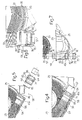
- a boiler 1 in particular a wall-mounted condensation heating boiler, comprises an airtight casing 2, in which are housed a combustion chamber 3 associated with a gas burner 4; a primary heat exchanger 5 for transferring heat from the fumes in combustion chamber 3 to a heating fluid circulating in a known circuit 6 (shown only partly in Figure 1 for the sake of simplicity); a fume circulating fan 7; and a secondary condensation heat exchanger 8 for recovering latent condensation heat from the fumes.
- Primary heat exchanger 5, fan 7, and secondary heat exchanger 8 are arranged in series with combustion chamber 3 along a fume path.
- Combustion chamber 3 is defined by a housing 9 closed airtight with respect to casing 2, and housing burner 4 and primary heat exchanger 5.
- Housing 9 comprises a substantially rectangular-based prismatic body having a gable-roof-shaped top wall 12 with two sloping (or generically oppositely inclined) sides 13, 14 joined by a ridge 15.
- Fan 7 and secondary heat exchanger 8 are located side by side on top of combustion chamber 3, and more specifically on respective sides 13 and 14; and fan 7 is located along the fume path between primary heat exchanger 5 and secondary heat exchanger 8.
- Burner 4 is a known aspirating atmospheric type connected by a feed conduit 16 to a gas mains; a known control unit 17 controls a known valve 18 inserted along feed conduit 16 to regulate the air/gas ratio supplied to burner 4; and combustion air is drawn from outside casing 2 along an intake conduit 19.
- Primary heat exchanger 5 is housed inside housing 9 defining combustion chamber 3, and comprises a conduit 22 connected to circuit 6 and along which the heating fluid circulates.
- Conduit 22 is finned externally, and is flowed over by the fumes produced in combustion chamber 3 and circulated by fan 7.
- Pipe 23 which is preferably made of aluminium, has a number of adjacent turns 27 contacting one another along axis A and defining a substantially cylindrical, radially inner gap 28.
- Pipe 23 has external finning 29 comprising a number of substantially annular fins 30 projecting radially from an outer lateral surface of pipe 23 and substantially crosswise to pipe 23.
- Enclosure 25 is substantially cylindrical, extends along axis A, and comprises two convex shells 31, 32, e.g. defined by respective one-piece pressure cast aluminium bodies, joined in fluidtight manner to define chamber 26.
- shells 31, 32 are joined, e.g. by screws (not shown), along respective edges 33, 34 lying in a mid-plane M of enclosure 25 and having grooves 35 for the insertion of seals 36.
- An end wall 37 of enclosure 25 has an access opening 38 closed by a removable cover 39 having a sealing ring 40 and fixed to enclosure 25, for example, by screws (not shown).
- a longitudinal end 41 of enclosure 25 comprises two openings 42, 43 defining a fume inlet and a heating fluid outlet respectively; a longitudinal end 44 of enclosure 25, opposite end 41, comprises two openings 45, 46 defining a fume outlet and a heating fluid inlet; openings 42, 46 (defining the fume and heating fluid inlets) are located substantially diametrically opposite each other, and substantially extend from opposite sides of enclosure 25; and openings 43, 45 (defining the heating fluid and fume outlets) are located diametrically opposite each other, and extend from opposite sides, substantially perpendicular to plan M.
- Openings 42, 43, 45, 46 are formed through enclosure 25, and are defined by respective collars 42c, 43c, 45c, 46c extending substantially radially outside enclosure 25. More specifically, openings 43, 46 are formed in shell 31, opening 45 is formed in shell 32, and opening 42 is defined by two facing portions formed in shells 31, 32. Opening 45 (fume outlet) has a seal 45g housed inside collar 45c, and is connected to an exhaust conduit 47.
- Enclosure 25 houses a known level sensor 51 which, in the event of condensate drainage failure (so that condensate accumulates above a given level inside enclosure 25), opens a known electric safety circuit (not shown) to cut off gas supply to burner 4.
- a substantially cylindrical deflecting member 53 is housed inside the gap 28 defined by turns 27, to cause the fumes inside chamber 26 to flow over finning 29.
- Fins 30 are positioned substantially contacting an inner lateral surface of chamber 26 and an outer lateral surface of deflecting member 53; and deflecting member 53 is inserted and removed through access opening 38, after first removing cover 39.
- Pipe 23 terminates, at respective opposite ends 54, 55, with two end portions 56, 57 having no fins and inserted respectively inside openings 46 and 43.
- secondary heat exchanger 8 comprises two connecting assemblies 58, 59 located at ends 54, 55 of pipe 23 and comprising respective first and second sealing means for connecting ends 54, 55 of pipe 23 in fluidtight manner to heating fluid circuit 6 and enclosure 25 respectively.
- connecting assembly 58 at opening 46 comprises a tubular fitting 64 made, for example, of aluminium, and having, at respective axially opposite ends, two inner seats 65, 66 in which to respectively insert end portion 56 of pipe 23 and a sleeve 67 for connection to circuit 6.
- Seat 65 has a circumferential groove 68 housing a radially inner sealing ring 69, which cooperates radially on the inside with end portion 56 force-fitted inside seat 65.
- Fitting 64 also comprises, on its outer lateral surface, a groove 70 housing a radially outer sealing ring 71, which cooperates radially on the outside and in fluidtight manner with an inner lateral surface of collar 46c defining opening 46. Fitting 64 is fixed to enclosure 25, and more specifically to collar 46c, in any known manner.
- connecting assembly 59 at opening 43 (defining the heating fluid outlet) comprises a tubular fitting 74 made, for example, of zinc-plated steel, and having, at respective axially opposite ends, two inner seats 75, 76 in which to respectively insert end portion 57 of pipe 23, and a sleeve (not shown) for connection to circuit 6.
- Seat 75 has a circumferential groove 78 housing a radially inner sealing ring 79, which cooperates radially on the inside with end portion 57 force-fitted inside seat 75.
- Connecting assembly 59 comprises a sealing ring 81 fitted to end portion 57 and housed inside a seat 82 formed inside collar 43c and having an annular shoulder 83. End portion 57 is fitted through collar 43c and force-fitted inside seat 75; and sealing ring 81 is gripped axially against shoulder 83 by a lock ring 84, in turn fitted and locked onto the outside of end portion 57.
- the connecting assemblies ensure that neither the fumes nor the heating fluid, and not even the acid condensate from the fumes, escape from the enclosure.
- the specific design and structure of the connecting assemblies also safeguard against electrolytic corrosion phenomena, with no need to weld the end portions of the pipe.
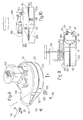
- fan 7 comprises a volute 101 defined by a metal casing 102 having a curved lateral wall 103 between a substantially flat bottom wall 104 (facing side 13 of combustion chamber 3) and a substantially flat top wall 105 parallel to each other; and a substantially straight delivery portion 106 positioned tangentially with respect to volute 101, and having a substantially straight, radially outer side 107 connected continuously to lateral wall 103 of volute 101.
- Volute 101 houses a known impeller 108, not shown in detail for the sake of simplicity, driven by a known electric motor 109 fitted to top wall 105, outside volute 101.
- Fan 7 is a centrifugal type having a substantially axial suction direction D1, and a delivery direction D2 substantially tangential with respect to impeller 108.
- Volute 101 has a suction hole 111 formed through the centre of bottom wall 104 and connected to combustion chamber 3 through an opening in side 13; and a delivery hole 112 located at the end of delivery portion 106 and connected to secondary heat exchanger 8.
- Fan 7 is associated with a flow (or pressure) sensor 113 connected to control unit 17 to regulate gas supply to burner 4 as a function of the values detected by sensor 113. More specifically, sensor 113 comprises a differential pressure switch 114; and pressure outlets 115, 116 located inside volute 101, downstream from impeller 108. Pressure switch 114 is known, e.g. of the type comprising two chambers separated by an elastically deformable membrane and connected to respective pressure outlets.
- Pressure outlets 115, 116 are dynamic and static respectively.
- Dynamic pressure outlet 115 comprises a venturi tube 117 extending tangentially inside volute 101, in a substantially laminar region of the flow generated by impeller 108 inside volute 101.
- venturi tube 117 extends along an axis substantially parallel to the flow direction.
- venturi tube 117 is housed inside delivery portion 106, with its axis substantially parallel to delivery portion 106, and is adjacent and substantially parallel to substantially straight side 107 of delivery portion 106.
- Venturi tube 117 has an inwardly tapering inlet 118; a substantially constant-section neck 119; and a flared portion 120.
- a tube 121 is connected to neck 119, is fitted through side 107, and is connected by a conduit 122 to a first input 123 of pressure switch 114.
- Static pressure outlet 116 is located in a turbulent region of the flow generated by impeller 108 in volute 101, upstream from dynamic pressure outlet 115, and comprises a tubular, e.g. straight, substantially cylindrical, probe 124 fitted through lateral wall 103 of volute 101.
- Probe 124 extends inside volute 101 substantially crosswise to the flow direction, and terminates inside volute 101 with an open end 125 substantially parallel to the flow direction of the stream flowing over it, and located close to the centre of the flow section at that point.
- the end 126 of probe 124 opposite end 125 and located outside volute 101 is connected by a conduit 127 to a second input 128 of pressure switch 114.
- Tube 121 and probe 124 are fixed to side 107 and lateral wall 103 respectively in known manner, e.g. by threaded fastening members 129, 130.
- Boiler 1 operates in substantially the same way as known condensation boilers.
- the gas from the mains and the air intake along intake conduit 19 are burned inside combustion chamber 3 in the ratio determined by control unit 17 and also on the basis of the values detected by sensor 113; and the combustion fumes flow over conduit 22 of primary heat exchanger 5 to transfer heat to the heating fluid.
- the fumes and combustion air are circulated by fan 7, which maintains combustion chamber 3 at lower than external atmospheric pressure.
- the fumes are then fed to secondary heat exchanger 8, where they transfer heat to the heating fluid, and acid condensate is formed and drained off along drain pipe 50.
- the condensate not drained off remains inside enclosure 25 and does not come into contact with any other component part of boiler 1.
- the fumes are then exhausted along exhaust conduit 47.
- the heating fluid from an input branch 6a of circuit 6 is heated in secondary heat exchange 8 before being fed to primary heat exchanger 5, from which it flows into an output branch 6b of circuit 6.
- boiler 1 Operation of boiler 1 is regulated on the basis of flow values detected by sensor 113, which operates in known manner. Briefly, the pressure signals picked up by means of pressure outlets 115, 116 inside volute 101 of fan 7 generate a differential pressure signal p which is converted by pressure switch 114 into a direct voltage. A microprocessor in control unit 17 assigns each p value a given gas supply quantity to burner 4, thus achieving constant efficiency values over the whole power range of boiler 1.
- pressure switch 114 In the event of a malfunction, or even flow being cut off inside volute 101 (e.g. due to clogging of exhaust conduit 47), pressure switch 114 detects a zero flow value and turns boiler 1 on.
- the specific locations of pressure outlets 115, 116 inside volute 101 provide for a high degree of stability of the pressure signals supplied to pressure switch 114.
- heating-only boilers i.e. simply producing hot water for a heating system (possibly combined with an external boiler)
- combination boilers i.e. producing heat for a heating system as well as hot water for domestic use.
Landscapes
- Engineering & Computer Science (AREA)
- General Engineering & Computer Science (AREA)
- Mechanical Engineering (AREA)
- Chemical & Material Sciences (AREA)
- Thermal Sciences (AREA)
- Combustion & Propulsion (AREA)
- Physics & Mathematics (AREA)
- Steam Or Hot-Water Central Heating Systems (AREA)
- Details Of Fluid Heaters (AREA)
- Air Supply (AREA)
- Combustion Of Fluid Fuel (AREA)
- Regulation And Control Of Combustion (AREA)
- Heat-Exchange Devices With Radiators And Conduit Assemblies (AREA)
- Instantaneous Water Boilers, Portable Hot-Water Supply Apparatuses, And Control Of Portable Hot-Water Supply Apparatuses (AREA)
Claims (16)
- Kessel (1) mit einer Verbrennungskammer (3), die einem Brenner (4) zugeordnet ist; einem primären Wärmetauscher (5) zum Transferieren von Wärme von dem in der Verbrennungskammer (3) erzeugten Rauch zu einem Wärmefluid; einem Gebläse (7) zum Umwälzen des Rauches; und einem sekundären Kondensationswärmetauscher (8) zum Wiedergewinnen latenter Kondensationswärme von dem Rauch; wobei der sekundäre Wärmetauscher (8) umfasst: einen Schlauch (23), der gewickelt ist, um eine spiralartige Leitung (24) zu bilden, die sich entlang einer Achse (A) erstreckt und in der das Wärmefluid umgewälzt wird; und ein Gehäuse (25), das eine im Wesentlichen zylindrische Kammer (26) aufweist, die den Schlauch (23) unterbringt und in der Rauch über die Außenseite des Schlauchs (23) strömt; wobei der Schlauch (23) externe Lamellen (29) und einen Zwischenraum (28) aufweist, der durch die Windungen (27) des Schlauchs (23) definiert ist, und ein Ablenkelement (53) unterbringt, durch das der Rauch innerhalb der Kammer (26) strömt und über die Lamellen (29) des Schlauchs (23) geleitet wird; wobei der Kessel dadurch gekennzeichnet ist, dass das Gebläse (7) und der sekundäre Wärmetauscher (8) nebeneinander oben auf der Verbrennungskammer (3) angeordnet sind.
- Kessel gemäß Anspruch 1, dadurch gekennzeichnet, dass die Lamellen (29) eine Anzahl von im Wesentlichen ringförmigen Rippen (30) umfassen, die radial von einer äußeren seitlichen Oberfläche des Schlauchs (23) und im Wesentlichen quergerichtet zu dem Schlauch (23) hervorragen.
- Kessel gemäß Anspruch 2, dadurch gekennzeichnet, dass die Rippen (30) im Wesentlichen eine innere seitliche Oberfläche der Kammer (26) und einer äußere seitliche Oberfläche des Ablenkelements (53) kontaktieren.
- Kessel gemäß einem der vorhergehenden Ansprüche, dadurch gekennzeichnet, dass das Gebläse (7) entlang eines Weges des Rauches zwischen dem primären Wärmetauscher (5) und dem sekundären Wärmetauscher (8) angeordnet ist.
- Kessel gemäß einem der vorhergehenden Ansprüche, dadurch gekennzeichnet, dass die Verbrennungskammer (3) eine giebeldachförmige obere Wand (12) mit zwei geneigten Seiten (13, 14) aufweist; wobei das Gebläse (7) und der sekundäre Wärmetauscher (8) oben auf jeweiligen Seiten (13, 14) angeordnet sind.
- Kessel gemäß einem der vorhergehenden Ansprüche, dadurch gekennzeichnet, dass das Gehäuse (25) durch zwei Schalen (31, 32) definiert ist, die auf eine fluiddichte Art und Weise verbunden sind, um die Kammer (26) zu definieren.
- Kessel gemäß einem der vorhergehenden Ansprüche, gekennzeichnet durch Umfassen von zwei Verbindungsanordnungen (58, 59), die an jeweiligen Enden (54, 55) des Schlauchs (23) angeordnet sind und jeweilige erste (69, 79) und zweite (71, 81) Dichtungsmittel zum Verbinden der Enden (54, 55) auf eine fluiddichte Art und Weise mit einem Wärmefluidkreislauf (6) bzw. dem Gehäuse (25) umfassen.
- Kessel gemäß Anspruch 7, dadurch gekennzeichnet, dass jede der Verbindungsanordnungen (58,59) umfasst: ein Anschlussteil (64,74), das mit einem jeweiligen Ende (54,55) des Schlauchs (23) verbunden ist; eine erste Dichtung (69,79), die radial auf der Außenseite und auf eine fluiddichte Art und Weise mit einem jeweiligen Abschnitt des Gehäuses (25) zusammenarbeitet; und eine zweite Dichtung (71,81), die radial auf der Innenseite und auf eine fluiddichte Art und Weise mit einem jeweiligen Endabschnitt (56,57) des Schlauchs (23) zusammenarbeitet.
- Kessel gemäß einem der vorhergehenden Ansprüche, dadurch gekennzeichnet, dass das Gebläse (7) umfasst: ein Spiralgehäuse (101), das ein Laufrad (108) unterbringt; und einen Strömungs- oder Drucksensor (113), der Druckauslässe (115,116) umfasst, die innerhalb des Spiralgehäuses (101), stromabwärts von dem Laufrad (108) angeordnet sind, und mit einer Steuereinheit (17) zum Steuern des Brenners (4) verbunden ist; wobei ein erster Druckauslass (115) in einer im Wesentlichen laminaren Region der durch das Laufrad (108) erzeugten Strömung innerhalb des Spiralgehäuses (101) angeordnet ist.
- Kessel gemäß Anspruch 9, dadurch gekennzeichnet, dass der erste Druckauslass (115) ein Venturi-Rohr (117) umfasst, das sich entlang einer Achse im Wesentlichen parallel zu der Richtung der Strömung erstreckt.
- Kessel gemäß Anspruch 10, dadurch gekennzeichnet, dass sich das Venturi-Rohr (117) tangential innerhalb des Spiralgehäuses (101) erstreckt.
- Kessel gemäß Anspruch 10 oder 11, dadurch gekennzeichnet, dass das Venturi-Rohr (117) nahe einer seitlichen Wand (103) des Spiralgehäuses (101) angeordnet ist.
- Kessel gemäß einem der Ansprüche 10 bis 12, gekennzeichnet durch Umfassen eines im Wesentlichen geraden Abgabeabschnitts (106), der tangential mit Bezug auf das Spiralgehäuse (101) angeordnet ist; wobei das Venturi-Rohr (117) innerhalb des Abgabeabschnitts (106) untergebracht ist und sich entlang einer Achse im Wesentlichen parallel zu dem Abgabeabschnitt (106) erstreckt.
- Kessel gemäß Anspruch 13, dadurch gekennzeichnet, dass das Venturi-Rohr (117) innerhalb des Abgabeabschnitts (106) benachbart und im Wesentlichen parallel zu einer Seite (107) des Abgabeabschnitts (106) untergebracht ist.
- Kessel gemäß einem der Ansprüche 10 bis 14, dadurch gekennzeichnet, dass ein zweiter Druckauslass (116) in einer turbulenten Region der Strömung angeordnet ist.
- Kessel gemäß Anspruch 15, dadurch gekennzeichnet, dass der zweite Druckauslass (116) eine rohrförmige Sonde (124) umfasst, die durch eine seitliche Wand (103) des Spiralgehäuses (101) angebracht ist und sich innerhalb des Spiralgehäuses (101) in einer Richtung im Wesentlichen quer zu der Strömung erstreckt.
Applications Claiming Priority (3)
| Application Number | Priority Date | Filing Date | Title |
|---|---|---|---|
| ITMI20022365 | 2002-11-07 | ||
| IT002365A ITMI20022365A1 (it) | 2002-11-07 | 2002-11-07 | Caldaia |
| PCT/IT2003/000722 WO2004042289A2 (en) | 2002-11-07 | 2003-11-06 | Boiler |
Publications (2)
| Publication Number | Publication Date |
|---|---|
| EP1565693A2 EP1565693A2 (de) | 2005-08-24 |
| EP1565693B1 true EP1565693B1 (de) | 2012-02-01 |
Family
ID=32310151
Family Applications (1)
| Application Number | Title | Priority Date | Filing Date |
|---|---|---|---|
| EP03780624A Expired - Lifetime EP1565693B1 (de) | 2002-11-07 | 2003-11-06 | Kessel |
Country Status (8)
| Country | Link |
|---|---|
| EP (1) | EP1565693B1 (de) |
| CN (1) | CN100561071C (de) |
| AT (1) | ATE544038T1 (de) |
| AU (1) | AU2003288721A1 (de) |
| ES (1) | ES2382915T3 (de) |
| IT (1) | ITMI20022365A1 (de) |
| PL (1) | PL212410B1 (de) |
| WO (1) | WO2004042289A2 (de) |
Cited By (1)
| Publication number | Priority date | Publication date | Assignee | Title |
|---|---|---|---|---|
| RU168562U1 (ru) * | 2016-09-27 | 2017-02-08 | Федеральное Государственное Автономное Образовательное Учреждение Высшего Профессионального Образования "Дальневосточный Федеральный Университет" (Двфу) | Котел водогрейный |
Families Citing this family (5)
| Publication number | Priority date | Publication date | Assignee | Title |
|---|---|---|---|---|
| GB2416827A (en) * | 2004-07-31 | 2006-02-08 | Boulter Buderus Ltd | Condensing unit |
| CN101672523B (zh) * | 2009-09-23 | 2011-01-05 | 张亚玉 | 旋风复合换热除尘无烟锅炉 |
| IT1399619B1 (it) * | 2010-04-14 | 2013-04-26 | Tecno Cover S R L | Metodo e apparato per il controllo della combustione in una caldaia o stufa e caldaia o stufa comprendente detto apparato. |
| ITUB20153466A1 (it) * | 2015-09-08 | 2017-03-08 | Riello Spa | Scambiatore di calore per una caldaia domestica o uno scaldacqua |
| IT201800010317A1 (it) * | 2018-11-14 | 2020-05-14 | Condevo S P A | Cella di scambio termico |
Family Cites Families (12)
| Publication number | Priority date | Publication date | Assignee | Title |
|---|---|---|---|---|
| FI81447C (fi) * | 1987-09-15 | 1990-10-10 | Ilmaterae Oy | Anordning foer uppmaetning av volymstroem i blaester. |
| US4993402A (en) * | 1989-12-18 | 1991-02-19 | Carrier Corporation | Fuel efficient rapid response water heating module |
| AT399219B (de) * | 1991-09-09 | 1995-04-25 | Vaillant Gmbh | Brennerbeheizter wasserspeicher |
| SE500539C2 (sv) * | 1991-06-12 | 1994-07-11 | Flaekt Ab | Sätt och anordning för bestämning av genomströmningsflödet i en ventilationsanläggning med en frisugande fläkt |
| FR2687212B1 (fr) | 1992-02-06 | 1999-04-30 | Chaffoteaux Et Maury | Perfectionnements aux dispositifs de securite pour chaudieres a gaz a flux force d'air ou analogues. |
| US5365459A (en) * | 1992-02-25 | 1994-11-15 | Perry Robert E | Continuous stack flow rate monitor |
| KR950002487B1 (ko) * | 1992-05-12 | 1995-03-20 | 주식회사금성사 | 가스보일러용 열교환장치 |
| US5775318A (en) * | 1995-10-30 | 1998-07-07 | Consolidated Industries Corp. | Forced air condensing furnace and heat exchanger manifold therefor |
| AT405879B (de) * | 1998-03-05 | 1999-12-27 | Vaillant Gmbh | Heizeinrichtung |
| GB9806306D0 (en) * | 1998-03-25 | 1998-05-20 | Ravenheat Manufacturing Ltd | Heating appliance |
| ES2240007T3 (es) * | 2000-03-03 | 2005-10-16 | Riello S.P.A. | Caldera de gas. |
| US6345769B2 (en) * | 2000-04-17 | 2002-02-12 | Canadian Gas Research Institute | Water heating apparatus with sensible and latent heat recovery |
-
2002
- 2002-11-07 IT IT002365A patent/ITMI20022365A1/it unknown
-
2003
- 2003-11-06 AU AU2003288721A patent/AU2003288721A1/en not_active Abandoned
- 2003-11-06 AT AT03780624T patent/ATE544038T1/de active
- 2003-11-06 CN CNB2003801029168A patent/CN100561071C/zh not_active Expired - Lifetime
- 2003-11-06 WO PCT/IT2003/000722 patent/WO2004042289A2/en not_active Application Discontinuation
- 2003-11-06 PL PL376774A patent/PL212410B1/pl unknown
- 2003-11-06 ES ES03780624T patent/ES2382915T3/es not_active Expired - Lifetime
- 2003-11-06 EP EP03780624A patent/EP1565693B1/de not_active Expired - Lifetime
Cited By (1)
| Publication number | Priority date | Publication date | Assignee | Title |
|---|---|---|---|---|
| RU168562U1 (ru) * | 2016-09-27 | 2017-02-08 | Федеральное Государственное Автономное Образовательное Учреждение Высшего Профессионального Образования "Дальневосточный Федеральный Университет" (Двфу) | Котел водогрейный |
Also Published As
| Publication number | Publication date |
|---|---|
| AU2003288721A8 (en) | 2004-06-07 |
| ITMI20022365A1 (it) | 2004-05-08 |
| CN1735777A (zh) | 2006-02-15 |
| AU2003288721A1 (en) | 2004-06-07 |
| PL212410B1 (pl) | 2012-09-28 |
| ATE544038T1 (de) | 2012-02-15 |
| PL376774A1 (pl) | 2006-01-09 |
| CN100561071C (zh) | 2009-11-18 |
| WO2004042289A2 (en) | 2004-05-21 |
| EP1565693A2 (de) | 2005-08-24 |
| WO2004042289A3 (en) | 2004-09-10 |
| ES2382915T3 (es) | 2012-06-14 |
Similar Documents
| Publication | Publication Date | Title |
|---|---|---|
| US4481935A (en) | Flue pipe connection | |
| US4730600A (en) | Condensing furnace | |
| EP1565693B1 (de) | Kessel | |
| US4867673A (en) | Condensing furnace | |
| US4465025A (en) | Steam generator | |
| MXPA06010145A (es) | Dispositivo de calentamiento/almacenamiento de fluido caldeado por combustible con sistema en bucle. | |
| NL8403236A (nl) | Verwarmingsketel voor een centrale verwarmingsinstallatie. | |
| US5361827A (en) | Economizer system for vapor generation apparatus | |
| CN218993687U (zh) | 冷凝式燃气热水器 | |
| CN111692757B (zh) | 风道组件、热交换结构及燃气热水器 | |
| CN220624405U (zh) | 冷凝器及热水器 | |
| KR20000063042A (ko) | 이열원 고온 재생기 | |
| CN213020347U (zh) | 一种可收集冷凝水的壁挂炉 | |
| KR100575185B1 (ko) | 콘덴싱 가스보일러용 열교환기의 연료공급관 | |
| JPS6143063Y2 (de) | ||
| RU31161U1 (ru) | Водогрейный котел | |
| KR200277473Y1 (ko) | 열교환기 | |
| ATE191272T1 (de) | Wärmetauscher | |
| GB2340594A (en) | Heating and destratifying apparatus | |
| JP2002267154A (ja) | ボイラ装置 | |
| CA1235970A (en) | Flue pipe connection | |
| KR20010047601A (ko) | 보일러용 급배기관 | |
| KR200358327Y1 (ko) | 보일러의 연도 조립구조 | |
| CA1314182C (en) | Condensing furnace | |
| EP0155855A2 (de) | Gasbefeuerter Wassererhitzer |
Legal Events
| Date | Code | Title | Description |
|---|---|---|---|
| PUAI | Public reference made under article 153(3) epc to a published international application that has entered the european phase |
Free format text: ORIGINAL CODE: 0009012 |
|
| 17P | Request for examination filed |
Effective date: 20050606 |
|
| AK | Designated contracting states |
Kind code of ref document: A2 Designated state(s): AT BE BG CH CY CZ DE DK EE ES FI FR GB GR HU IE IT LI LU MC NL PT RO SE SI SK TR |
|
| AX | Request for extension of the european patent |
Extension state: AL LT LV MK |
|
| DAX | Request for extension of the european patent (deleted) | ||
| 17Q | First examination report despatched |
Effective date: 20060630 |
|
| GRAP | Despatch of communication of intention to grant a patent |
Free format text: ORIGINAL CODE: EPIDOSNIGR1 |
|
| GRAS | Grant fee paid |
Free format text: ORIGINAL CODE: EPIDOSNIGR3 |
|
| GRAA | (expected) grant |
Free format text: ORIGINAL CODE: 0009210 |
|
| RAP1 | Party data changed (applicant data changed or rights of an application transferred) |
Owner name: RIELLO S.P.A. |
|
| AK | Designated contracting states |
Kind code of ref document: B1 Designated state(s): AT BE BG CH CY CZ DE DK EE ES FI FR GB GR HU IE IT LI LU MC NL PT RO SE SI SK TR |
|
| REG | Reference to a national code |
Ref country code: GB Ref legal event code: FG4D |
|
| REG | Reference to a national code |
Ref country code: AT Ref legal event code: REF Ref document number: 544038 Country of ref document: AT Kind code of ref document: T Effective date: 20120215 Ref country code: CH Ref legal event code: EP |
|
| REG | Reference to a national code |
Ref country code: DE Ref legal event code: R096 Ref document number: 60339917 Country of ref document: DE Effective date: 20120329 |
|
| REG | Reference to a national code |
Ref country code: NL Ref legal event code: T3 |
|
| REG | Reference to a national code |
Ref country code: ES Ref legal event code: FG2A Ref document number: 2382915 Country of ref document: ES Kind code of ref document: T3 Effective date: 20120614 |
|
| PG25 | Lapsed in a contracting state [announced via postgrant information from national office to epo] |
Ref country code: BE Free format text: LAPSE BECAUSE OF FAILURE TO SUBMIT A TRANSLATION OF THE DESCRIPTION OR TO PAY THE FEE WITHIN THE PRESCRIBED TIME-LIMIT Effective date: 20120201 Ref country code: GR Free format text: LAPSE BECAUSE OF FAILURE TO SUBMIT A TRANSLATION OF THE DESCRIPTION OR TO PAY THE FEE WITHIN THE PRESCRIBED TIME-LIMIT Effective date: 20120502 Ref country code: PT Free format text: LAPSE BECAUSE OF FAILURE TO SUBMIT A TRANSLATION OF THE DESCRIPTION OR TO PAY THE FEE WITHIN THE PRESCRIBED TIME-LIMIT Effective date: 20120601 Ref country code: FI Free format text: LAPSE BECAUSE OF FAILURE TO SUBMIT A TRANSLATION OF THE DESCRIPTION OR TO PAY THE FEE WITHIN THE PRESCRIBED TIME-LIMIT Effective date: 20120201 |
|
| REG | Reference to a national code |
Ref country code: AT Ref legal event code: MK05 Ref document number: 544038 Country of ref document: AT Kind code of ref document: T Effective date: 20120201 |
|
| PG25 | Lapsed in a contracting state [announced via postgrant information from national office to epo] |
Ref country code: CY Free format text: LAPSE BECAUSE OF FAILURE TO SUBMIT A TRANSLATION OF THE DESCRIPTION OR TO PAY THE FEE WITHIN THE PRESCRIBED TIME-LIMIT Effective date: 20120201 |
|
| PG25 | Lapsed in a contracting state [announced via postgrant information from national office to epo] |
Ref country code: EE Free format text: LAPSE BECAUSE OF FAILURE TO SUBMIT A TRANSLATION OF THE DESCRIPTION OR TO PAY THE FEE WITHIN THE PRESCRIBED TIME-LIMIT Effective date: 20120201 Ref country code: DK Free format text: LAPSE BECAUSE OF FAILURE TO SUBMIT A TRANSLATION OF THE DESCRIPTION OR TO PAY THE FEE WITHIN THE PRESCRIBED TIME-LIMIT Effective date: 20120201 Ref country code: SE Free format text: LAPSE BECAUSE OF FAILURE TO SUBMIT A TRANSLATION OF THE DESCRIPTION OR TO PAY THE FEE WITHIN THE PRESCRIBED TIME-LIMIT Effective date: 20120201 Ref country code: RO Free format text: LAPSE BECAUSE OF FAILURE TO SUBMIT A TRANSLATION OF THE DESCRIPTION OR TO PAY THE FEE WITHIN THE PRESCRIBED TIME-LIMIT Effective date: 20120201 Ref country code: CZ Free format text: LAPSE BECAUSE OF FAILURE TO SUBMIT A TRANSLATION OF THE DESCRIPTION OR TO PAY THE FEE WITHIN THE PRESCRIBED TIME-LIMIT Effective date: 20120201 Ref country code: SI Free format text: LAPSE BECAUSE OF FAILURE TO SUBMIT A TRANSLATION OF THE DESCRIPTION OR TO PAY THE FEE WITHIN THE PRESCRIBED TIME-LIMIT Effective date: 20120201 |
|
| PG25 | Lapsed in a contracting state [announced via postgrant information from national office to epo] |
Ref country code: SK Free format text: LAPSE BECAUSE OF FAILURE TO SUBMIT A TRANSLATION OF THE DESCRIPTION OR TO PAY THE FEE WITHIN THE PRESCRIBED TIME-LIMIT Effective date: 20120201 |
|
| PLBE | No opposition filed within time limit |
Free format text: ORIGINAL CODE: 0009261 |
|
| STAA | Information on the status of an ep patent application or granted ep patent |
Free format text: STATUS: NO OPPOSITION FILED WITHIN TIME LIMIT |
|
| 26N | No opposition filed |
Effective date: 20121105 |
|
| PG25 | Lapsed in a contracting state [announced via postgrant information from national office to epo] |
Ref country code: AT Free format text: LAPSE BECAUSE OF FAILURE TO SUBMIT A TRANSLATION OF THE DESCRIPTION OR TO PAY THE FEE WITHIN THE PRESCRIBED TIME-LIMIT Effective date: 20120201 |
|
| REG | Reference to a national code |
Ref country code: DE Ref legal event code: R097 Ref document number: 60339917 Country of ref document: DE Effective date: 20121105 |
|
| REG | Reference to a national code |
Ref country code: CH Ref legal event code: PL |
|
| PG25 | Lapsed in a contracting state [announced via postgrant information from national office to epo] |
Ref country code: LI Free format text: LAPSE BECAUSE OF NON-PAYMENT OF DUE FEES Effective date: 20121130 Ref country code: CH Free format text: LAPSE BECAUSE OF NON-PAYMENT OF DUE FEES Effective date: 20121130 Ref country code: BG Free format text: LAPSE BECAUSE OF FAILURE TO SUBMIT A TRANSLATION OF THE DESCRIPTION OR TO PAY THE FEE WITHIN THE PRESCRIBED TIME-LIMIT Effective date: 20120501 |
|
| REG | Reference to a national code |
Ref country code: IE Ref legal event code: MM4A |
|
| PG25 | Lapsed in a contracting state [announced via postgrant information from national office to epo] |
Ref country code: IE Free format text: LAPSE BECAUSE OF NON-PAYMENT OF DUE FEES Effective date: 20121106 |
|
| PG25 | Lapsed in a contracting state [announced via postgrant information from national office to epo] |
Ref country code: TR Free format text: LAPSE BECAUSE OF FAILURE TO SUBMIT A TRANSLATION OF THE DESCRIPTION OR TO PAY THE FEE WITHIN THE PRESCRIBED TIME-LIMIT Effective date: 20120201 Ref country code: MC Free format text: LAPSE BECAUSE OF NON-PAYMENT OF DUE FEES Effective date: 20121130 |
|
| PG25 | Lapsed in a contracting state [announced via postgrant information from national office to epo] |
Ref country code: LU Free format text: LAPSE BECAUSE OF NON-PAYMENT OF DUE FEES Effective date: 20121106 |
|
| PG25 | Lapsed in a contracting state [announced via postgrant information from national office to epo] |
Ref country code: HU Free format text: LAPSE BECAUSE OF FAILURE TO SUBMIT A TRANSLATION OF THE DESCRIPTION OR TO PAY THE FEE WITHIN THE PRESCRIBED TIME-LIMIT Effective date: 20031106 |
|
| REG | Reference to a national code |
Ref country code: FR Ref legal event code: PLFP Year of fee payment: 13 |
|
| REG | Reference to a national code |
Ref country code: FR Ref legal event code: PLFP Year of fee payment: 14 |
|
| REG | Reference to a national code |
Ref country code: FR Ref legal event code: PLFP Year of fee payment: 15 |
|
| PGFP | Annual fee paid to national office [announced via postgrant information from national office to epo] |
Ref country code: NL Payment date: 20201126 Year of fee payment: 18 |
|
| PGFP | Annual fee paid to national office [announced via postgrant information from national office to epo] |
Ref country code: DE Payment date: 20201130 Year of fee payment: 18 Ref country code: GB Payment date: 20201126 Year of fee payment: 18 |
|
| REG | Reference to a national code |
Ref country code: DE Ref legal event code: R119 Ref document number: 60339917 Country of ref document: DE |
|
| REG | Reference to a national code |
Ref country code: NL Ref legal event code: MM Effective date: 20211201 |
|
| GBPC | Gb: european patent ceased through non-payment of renewal fee |
Effective date: 20211106 |
|
| PG25 | Lapsed in a contracting state [announced via postgrant information from national office to epo] |
Ref country code: NL Free format text: LAPSE BECAUSE OF NON-PAYMENT OF DUE FEES Effective date: 20211201 |
|
| PG25 | Lapsed in a contracting state [announced via postgrant information from national office to epo] |
Ref country code: GB Free format text: LAPSE BECAUSE OF NON-PAYMENT OF DUE FEES Effective date: 20211106 Ref country code: DE Free format text: LAPSE BECAUSE OF NON-PAYMENT OF DUE FEES Effective date: 20220601 |
|
| PGFP | Annual fee paid to national office [announced via postgrant information from national office to epo] |
Ref country code: IT Payment date: 20221110 Year of fee payment: 20 Ref country code: FR Payment date: 20221122 Year of fee payment: 20 Ref country code: ES Payment date: 20221212 Year of fee payment: 20 |
|
| P01 | Opt-out of the competence of the unified patent court (upc) registered |
Effective date: 20230529 |
|
| REG | Reference to a national code |
Ref country code: ES Ref legal event code: FD2A Effective date: 20231201 |
|
| PG25 | Lapsed in a contracting state [announced via postgrant information from national office to epo] |
Ref country code: ES Free format text: LAPSE BECAUSE OF EXPIRATION OF PROTECTION Effective date: 20231107 |
|
| PG25 | Lapsed in a contracting state [announced via postgrant information from national office to epo] |
Ref country code: ES Free format text: LAPSE BECAUSE OF EXPIRATION OF PROTECTION Effective date: 20231107 |