EP1565613B2 - Papermaking screen - Google Patents
Papermaking screen Download PDFInfo
- Publication number
- EP1565613B2 EP1565613B2 EP03811353.6A EP03811353A EP1565613B2 EP 1565613 B2 EP1565613 B2 EP 1565613B2 EP 03811353 A EP03811353 A EP 03811353A EP 1565613 B2 EP1565613 B2 EP 1565613B2
- Authority
- EP
- European Patent Office
- Prior art keywords
- fabric
- weft
- yarn
- yarns
- binder
- Prior art date
- Legal status (The legal status is an assumption and is not a legal conclusion. Google has not performed a legal analysis and makes no representation as to the accuracy of the status listed.)
- Expired - Lifetime
Links
Images

Classifications
-
- D—TEXTILES; PAPER
- D21—PAPER-MAKING; PRODUCTION OF CELLULOSE
- D21F—PAPER-MAKING MACHINES; METHODS OF PRODUCING PAPER THEREON
- D21F1/00—Wet end of machines for making continuous webs of paper
- D21F1/0027—Screen-cloths
- D21F1/0036—Multi-layer screen-cloths
- D21F1/0045—Triple layer fabrics
-
- Y—GENERAL TAGGING OF NEW TECHNOLOGICAL DEVELOPMENTS; GENERAL TAGGING OF CROSS-SECTIONAL TECHNOLOGIES SPANNING OVER SEVERAL SECTIONS OF THE IPC; TECHNICAL SUBJECTS COVERED BY FORMER USPC CROSS-REFERENCE ART COLLECTIONS [XRACs] AND DIGESTS
- Y10—TECHNICAL SUBJECTS COVERED BY FORMER USPC
- Y10S—TECHNICAL SUBJECTS COVERED BY FORMER USPC CROSS-REFERENCE ART COLLECTIONS [XRACs] AND DIGESTS
- Y10S162/00—Paper making and fiber liberation
- Y10S162/90—Papermaking press felts
-
- Y—GENERAL TAGGING OF NEW TECHNOLOGICAL DEVELOPMENTS; GENERAL TAGGING OF CROSS-SECTIONAL TECHNOLOGIES SPANNING OVER SEVERAL SECTIONS OF THE IPC; TECHNICAL SUBJECTS COVERED BY FORMER USPC CROSS-REFERENCE ART COLLECTIONS [XRACs] AND DIGESTS
- Y10—TECHNICAL SUBJECTS COVERED BY FORMER USPC
- Y10S—TECHNICAL SUBJECTS COVERED BY FORMER USPC CROSS-REFERENCE ART COLLECTIONS [XRACs] AND DIGESTS
- Y10S162/00—Paper making and fiber liberation
- Y10S162/903—Paper forming member, e.g. fourdrinier, sheet forming member
Definitions
- the invention relates to a papermaking fabric.
- the sheet forming unit is usually designed as a twin-wire former, in many cases as a gap former. Characteristic of the machines is that the sheet forming operation takes place immediately between two paper machine wires in a relatively short dewatering zone. Due to this short distance and the high production speed, the time for sheet formation is reduced to a few milliseconds. During this period, the solids content or dry content of the pulp suspension must be increased from about 1% to about 20%. This means for the paper machine screens that they have to have a very high dewatering performance, but still can leave no markings in the paper and provide a high fiber support.
- the one solution is characterized in that the two individual fabric layers are joined together by means of a weft or transverse thread.
- Another solution provides that the connection is made by means of a longitudinal or warp thread.
- the two layers must be joined by a weft, in particular a binding weft.
- the binding threads additionally used change the very homogeneous upper side, which in practice leads in part to unwanted markings in the paper.
- the binding threads are always thinner, but this has the disadvantage that the durability for the connection of the individual layers of fabric decreases accordingly.
- it has been found in practical use that it can come to "looping" of the binding weft threads, resulting in the separation of the individual layers and the fabric is unusable.
- DE 42 29 828 A is a paper machine screen in the form of a composite fabric known, in particular for the sheet forming zone, consisting of at least two superimposed screen fabrics, which are formed at least one ply and connected by transverse in and / or longitudinal binding threads together, wherein one of the screen fabric as a definition fabric with the mechanical properties of the composite fabric in terms of elongation and stiffness determining training and the other screen fabric is designed as a reaction fabric with a higher elongation and lower stiffness than the definition fabric.
- the so-called internal wear is reduced so much that the service life is essentially determined by the external wear, that is to say the abrasion occurring on the outer surface of the sieve.
- US 5,482,567 A a three-ply fabric for use in the sheet forming area of a paper machine
- US 5,826,627 A discloses a papermaker wire with paired weft binder threads
- US 4,729,412 A discloses a double-layered forming screen with binding warp threads.
- the invention has the object to help avoid the disadvantages described in the prior art, in particular to create a paper machine screen, which is characterized by high strength values, in particular has a high degree of lateral stability and offers comparable drainage services, how the known solutions as well as the formation of markings in the paper helps to avoid.
- a problem solves a papermaking machine with the features of claim 1 in its entirety.
- the respective binder thread on the paper side engages at defined locations warp threads of the individual fabric, which are attacked on its opposite side under investment of at least one weft of this single fabric, the compound of the two fabric layers (paper side and running side) turn by binding threads realized, but then completely integrate into the fabric structure of the paper side and thereby support by the special type of connection each binding point thus created, so that the binding threads thus remain on a plane with the shots and the remaining warp threads.
- the warp threads are supported from below by the associated weft thread of the single fabric of the paper side at the points where they are pulled through the binding thread into the fabric interior.
- the upper weft (paper side) a material that supports the transverse stability of the fabric, so for example a polyester material, whereas in the above-mentioned known solutions when using a pair of binding shot both materials the same have to be optimized and with respect to the layer connection, usually using polyamides.
- the number of binding sites ie the contact between the binding weft and upper or lower chain of the paper side and running side, does not decrease compared to the known solutions.
- the diameter of the binding thread corresponds to that of the upper weft, which leads to a high strength of the connection between the fabric layers.
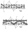
- detectable solution according to the Fig. 1 consists of the paper machine screen of two individual fabrics, looking in the direction of the Fig. 1
- the upper single fabric consists of a set of weft yarns 2 as upper weft yarns and warp yarns 1 as upper warp yarns.
- the underlying running side is also formed from a set of wefts 6 as Unterschußfäden and warp threads 5 as Unterkettfäden.
- the known solution has a plain weave and the lower fabric is designed as a five-shaft fabric in relation to a repeat.
- binding weft thread 3 shows the two individual fabrics are connected to each other via a binding weft thread 3, wherein in the drawing plane and out of this a plurality of pertinent binding weft threads 3 (not shown) are arranged in sequence and thus produce the necessary connection of the individual fabric layers for the papermaking fabric.
- the binding threads 3 are used in the direction of the fabric in front of and behind the upper weft threads 2 used to establish the connection of the individual fabric layers, so that thereby the actually very homogeneous top of the paper side of the screen is adversely affected such that it is in the Practice may come to unwanted marks in the paper. Accordingly, in order that the known binding weft threads 3 interfere as little as possible, they are always thinner, so that when using the known papermachine sieves separation of the individual tissue layers can occur and consequently failure of the sieve as such.
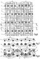
- Fig. 3 shows a detail of the top view of the top or paper side of the paper machine wire according to the invention and the section AA according to Fig. 4 refers to the view of the upper shot without binding shot, whereas the section BB the view of the upper shot with binding shot after the Fig. 3 concerns.
- FIG. 5 shows how the connection of the two single fabric layers for paper and running side is realized by binding threads 3, of which exemplified in Fig. 5 shown in detail the course of such a binding thread 3, which is completely integrated into the fabric structure on the paper side, in which overlaps on the paper side at defined locations of the respective binding thread 3 the assignable warp threads 1 of the individual fabric, at least on its opposite side a weft 2 of this individual tissue are under attack.
- This encroachment or attack is in the Fig. 5 represented by the reference numerals 7 and 8.
- the binding point is supported by the opposite side, so as to ensure that this on one level with the other shot - And warp threads 4 and 1 remains.
- the upper weft thread 2 thus also runs evenly at the point at which a weave is made without being integrated into the lower weave. Only at the points where the binding shot 3 runs over the upper chain, a short exchange of upper 2 and binding shot 3 is made.
- the inventively designed binding solution based on a repeat as a five-shaft binding provides that four warp threads 5 are engaged by the weft threads 6 of the lower weave and a warp thread 5 is overlapped in succession, the respective binding weft thread 3 rising obliquely from the lower weave into the upper fabric at the location of this overlap 9 replaced.
- the respective binding weft thread 3 has substantially the same diameter as the respective weft thread 2 of the single fabric on the paper side.
- the warp threads 5 and the weft threads 6 of the lower fabric that is, on the running side, each have a larger diameter in diameter than the assignable thread systems on the upper or paper side of the papermachine fabric.
- the respective overlap 7 of the respective binding thread 3 is consequently separated with respect to a weft thread 2 from three intervening warp threads 1, wherein at the location of the middle warp thread 1 of this trimming group the binding thread 3 briefly comprises an underlying warp thread 5 engages under the overlap 6 before the attack 9.
- the binding thread 3 may consist of different materials, preferably to increase the transverse stability of the screen, the upper weft threads 2 made of a polyester material and the binding wefts 3 of a polyamide material.
- the upper weft 4 after the Fig. 4 corresponds to its embodiment of the upper weft thread 2 with previously shown binding weft thread 3.
- the different numbering was chosen only to be in the representation of the Fig. 3 to achieve a better understanding of the tissue pattern in the plan view.
- this embodiment corresponds largely to the first embodiment described first; only instead of a five-shaft underside, the lower fabric or the underside (running side) a four-shaft binding was used for this purpose.
- the warp thread 1 overlapped by the binder thread 3 and undercut by the upper weft thread 2 is in turn supported by a vertically underlying warp thread 5 of the lower fabric, the lower weft thread 6 extending above the lower warp thread 5 at the support point.
- the binding of the binding thread 3 is then carried out for the lower fabric in the range of three successive Unterkettfäden 5, wherein the middle Unterkettfaden 5 of a triad of the binding yarn 3 and the two adjacent Unterkettfäden 5 are so overlapped by the binder yarn 3.
- the roof-like configuration in the region of the overlap 7 for the upper warp thread 1 is then in a parallel arrangement its equivalent, in the underlying overlap 9 of the supporting Unterkettfadens 5 through the lower weft thread. 6
Landscapes
- Paper (AREA)
- Woven Fabrics (AREA)
- Developing Agents For Electrophotography (AREA)
- Storage Of Web-Like Or Filamentary Materials (AREA)
- Polishing Bodies And Polishing Tools (AREA)
- Diaphragms For Electromechanical Transducers (AREA)
- Glass Compositions (AREA)
Abstract
Description
Die Erfindung betrifft ein Papiermaschinensieb.The invention relates to a papermaking fabric.
In der papiererzeugenden Industrie werden heute immer mehr Hochleistungs-Papiermaschinen mit Geschwindigkeiten bis zu 2000 m/min und Arbeitsbreiten über 10 m eingesetzt. Die Blattbildungseinheit ist dabei in aller Regel als Doppelsiebformer ausgeführt, in vielen Fällen auch als Spaltformer. Charakteristisch für die Maschinen ist, dass der Blattbildungsvorgang sofort zwischen zwei Papiermaschinensieben in einer relativ kurzen Entwässerungszone stattfindet. Durch diese kurze Strecke und die hohe Produktionsgeschwindigkeit reduziert sich die Zeit für die Blattbildung auf einige Millisekunden. In diesem Zeitraum muß der Feststoffanteil bzw. Trockengehalt der Faserstoffsuspension von ca. 1 % auf etwa 20 % angehoben werden. Das bedeutet für die Papiermaschinensiebe, dass sie eine sehr hohe Entwässerungsleistung besitzen müssen, aber trotzdem keine Markierungen im Papier hinterlassen dürfen und eine hohe Faserunterstützung bieten.Today, more and more high-performance paper machines with speeds up to 2000 m / min and working widths over 10 m are used in the paper-producing industry. The sheet forming unit is usually designed as a twin-wire former, in many cases as a gap former. Characteristic of the machines is that the sheet forming operation takes place immediately between two paper machine wires in a relatively short dewatering zone. Due to this short distance and the high production speed, the time for sheet formation is reduced to a few milliseconds. During this period, the solids content or dry content of the pulp suspension must be increased from about 1% to about 20%. This means for the paper machine screens that they have to have a very high dewatering performance, but still can leave no markings in the paper and provide a high fiber support.
Ein weiterer wichtiger Punkt ist die Querstabilität der Siebbespannung, die maßgebend ist für die Gleichmäßigkeit des Dicken- und Feuchtigkeitsprofils der Papierbahn. Gerade bei den modernen Maschinen mit großen Arbeitsbreiten sind die diesbezüglichen Anforderungen sehr hoch angesetzt. Zur Verbesserung der Formation werden in der Blattbildungszone mithin immer häufiger Formierleisten eingesetzt, die wechselseitig auf den Laufseiten der Siebe angeordnet sind und gegen diese gedrückt werden. Dadurch kommt es zu einer schnell wechselnden, in Längsrichtung verlaufenden Durchbiegung der Bespannung der Siebe.Another important point is the transverse stability of the screen covering, which is decisive for the uniformity of the thickness and moisture profile of the paper web. Especially in the modern machines with large working widths, the relevant requirements are set very high. In order to improve the formation, forming strips are therefore increasingly used in the sheet-forming zone, which are mutually arranged on the running sides of the wires and pressed against them. This leads to a rapidly changing, longitudinally extending deflection of the fabric of the screens.
Um diesen Anforderungen gerecht zu werden und, um insbesondere eine Verbindung der Einzelgewebe der Papierseite und der Laufseite miteinander zu erreichen, existieren im Stand der Technik grundsätzlich zwei unterschiedliche Lösungsansätze. Die eine Lösung ist dadurch charakterisiert, dass die beiden Einzelgewebelagen mittels eines Schuß- oder Querfadens miteinander verbunden werden. Eine andere Lösung sieht vor, dass die Verbindung mittels eines Längs- oder Kettfadens erfolgt. Vor allem wenn man unterschiedliche Kettdurchmesserauf der Lauf- und der Papierseite einsetzen will, kommen diese bekannten Ansätze jedoch nicht mehr in Frage.In order to meet these requirements and, in particular, to achieve a connection of the individual fabrics of the paper side and the running side with one another, there are basically two different approaches to solution in the prior art. The one solution is characterized in that the two individual fabric layers are joined together by means of a weft or transverse thread. Another solution provides that the connection is made by means of a longitudinal or warp thread. Especially if you want to use different Kettdurchmesserauf the run and the paper side, these known approaches are no longer in question.
Soll demgemäß die Ausbildung der beiden Einzelgewebe speziell auf eine feine Papierseite mit dünnen Durchmessern und eine grobe Laufseite mit dicken Durchmessern ausgerichtet sein, um dergestalt zu hohen Stabilitätswerten zu kommen, muß die Verbindung beider Lagen durch einen Schuß, insbesondere Bindeschuß erfolgen. Auch hierfür bietet der Stand derTechnik entsprechende Vorschläge.Accordingly, if the formation of the two individual fabrics is to be specifically aimed at a fine paper side with thin diameters and a coarse running side with thick diameters in order to achieve high stability values, the two layers must be joined by a weft, in particular a binding weft. Again, the state of the art offers corresponding proposals.
So besteht die Möglichkeit beide Einzelgewebe durch einen zusätzlichen Binde- oder Heftfaden, derweder in das Bindungsbild des Obergewebes (Papierseite) noch des Untergewebes (Laufseite) gehört, miteinander zu verweben. Eine solche Lösung ist beispielsweise durch das Papiermaschinensieb der
Bei solchen bekannten Lösungen verändern die zusätzlich verwendeten Bindefäden die an sich sehr homogene Oberseite, was in der Praxis teilweise zu ungewollten Markierungen im Papier führt. Um dem zu begegnen werden die Bindefäden immer dünner ausgebildet, was jedoch den Nachteil hat, dass die Dauerhaltbarkeit für die Verbindung der einzelnen Gewebelagen entsprechend abnimmt. Ferner hat es sich beim praktischen Einsatz gezeigt, dass es zum "Durchschleifen" der Bindeschußfäden kommen kann, was zurTrennung der Einzellagen führt und das Gewebe unbrauchbar werden läßt.In such known solutions, the binding threads additionally used change the very homogeneous upper side, which in practice leads in part to unwanted markings in the paper. To counter this, the binding threads are always thinner, but this has the disadvantage that the durability for the connection of the individual layers of fabric decreases accordingly. Furthermore, it has been found in practical use that it can come to "looping" of the binding weft threads, resulting in the separation of the individual layers and the fabric is unusable.
Bei einer anderen bekannten Lösung werden komplette Oberschüsse durch Paare von bindenden Strukturfäden ersetzt. Dabei kann in Abhängigkeit des gewählten Gewebetypes das Verhältnis von echten Oberschüssen durch Schuß- oder Kettfäden zu den Bindeschußpaaren variieren. So sind durch die PCT-Veröffentlichungen
Trotz der guten Verbindung der beiden Einzelgewebe miteinander besteht bei diesen bekannten Lösungen ein wesentlicher Nachteil darin, dass an den Kreuzungspunkten der Bindeschüsse die Oberkette der Papierseite nicht unterstützt wird. Betrachtet man bei diesen bekannten Lösungen den Verlauf eines "vollständigen" Oberschusses, so erkennt man, dass durch die alternierende Bindung von Oberschuß und Oberkette beide Fäden auf einem Höhenniveau liegen, mit der Folge, dass sowohl die Kett- als auch die Schußverkröpfungen in einer Ebene liegen. Durch den Einsatz der Bindepaare fehlt nun diese Unterstützung an allen Kreuzungsstellen und alle Fäden nehmen die hauptsächlichen Kräfte entlang ihrer jeweiligen Längsachse auf, die an den Kreuzungsstellen in das Gewebeinnere zeigt. Dieser Nachteil der fehlenden Unterstützung entsteht insbesondere dann, wenn Oberschuß und Bindepaar in alternierender Folge eingesetzt werden, also beispielsweise ein vollständiger Oberschuß einem Bindepaar folgt und darauf wieder ein Oberschuß. Um dann die bevorzugt bekannte Leinwandbindung zu realisieren, muß der nächstfolgende Oberschuß über den Kettfaden verlaufen, der zuvor über dem Kreuzungspunkt lag, und wird dadurch zusätzlich in das Gewebeinnere gezogen. Dies führt dazu, dass entweder jeder zweite Oberkettfaden tiefer im Gewebe liegt oder keiner der Kettfäden auf dem Niveau der Schußfäden liegen kann. Dies führt zu einem ungleichmäßigen Gewebeverlauf auf der Papierseite, was zu unerwünschten Markierungen im Papier führen kann.Despite the good connection of the two individual fabrics together, a major disadvantage of these known solutions is that the upper chain of the paper side is not supported at the crossing points of the binding shots. Looking at the course of a "complete" upper weft in these known solutions, it can be seen that both threads are at a height level due to the alternating binding of the upper weft and the upper weft, with the result that both the warp and the weft offsets are in one plane lie. The use of binding pairs now lacks this support at all intersections and all the threads absorb the major forces along their respective longitudinal axis, which points into the tissue interior at the intersections. This disadvantage of the lack of support arises in particular when the upper weft and binding pair are used in an alternating sequence, that is to say, for example, a complete upper weft follows a binding pair and then again an upper weft. In order then to realize the preferably known plain weave, the next following upper weft must extend over the warp thread, which previously lay above the crossing point, and thereby becomes additional pulled into the fabric interior. As a result, either every other upper warp thread lies deeper in the fabric or none of the warp threads can be at the level of the weft threads. This results in uneven webbing on the paper side, which can lead to unwanted marks in the paper.
Durch die
Ausgehend von diesem Stand der Technik, liegt der Erfindung die Aufgabe zugrunde die beschriebenen Nachteile im Stand der Technik vermeiden zu helfen, insbesondere ein Papiermaschinensieb zu schaffen, das sich durch hohe Festigkeitswerte auszeichnet, insbesondere ein hohes Maß an Querstabilität hat und dabei vergleichbare Entwässerungsleistungen bietet, wie die bekannten Lösungen sowie die Bildung von Markierungen im Papier vermeiden hilft. Eine derartige Aufgabe löst ein Papiermaschinensieb mit den Merkmalen des Patentanspruches 1 in seiner Gesamtheit.Based on this prior art, the invention has the object to help avoid the disadvantages described in the prior art, in particular to create a paper machine screen, which is characterized by high strength values, in particular has a high degree of lateral stability and offers comparable drainage services, how the known solutions as well as the formation of markings in the paper helps to avoid. Such a problem solves a papermaking machine with the features of
Dadurch, dass gemäß Patentanspruch 1 der jeweilige Bindefaden auf der Papierseite an definierten Stellen Kettfäden des Einzelgewebes übergreift, die an ihrer gegenüberliegenden Seite unter Anlage von mindestens einem Schussfaden dieses Einzelgewebes untergriffen sind, wird die Verbindung der beiden Gewebelagen (Papierseite und Laufseite) wiederum durch Bindefäden realisiert, die sich aber dann in die Gewebestruktur der Papierseite vollständig integrieren und dabei durch die spezielle Art der Verbindung die jeweils derart erzeugte Bindestelle unterstützen, so dass die Bindefäden somit auf einer Ebene mit den Schüssen und den restlichen Kettfäden verbleiben. Mit dieser Bindungsidee ist ein hochfestes Papiermaschinensieb erreicht mit sehr guter Entwässerungsleistung und gleichmäßigem Aufbau, insbesondere auf der Papierseite, so dass die nicht gewünschten Markierungen im Papier vermieden sind.Characterized in that according to
MitdererfindungsgemäßenLösungisterreicht, dass die Kettfäden an den Stellen, wo sie durch den Bindefaden ins Gewebeinnere gezogen werden, von unten durch den zugeordneten Schußfaden des Einzelgewebes der Papierseite unterstützt sind. Durch die funktionale Trennung von Ober- und Bindeschuß ist darüber hinaus ermöglicht, für den Oberschuß (Papierseite) ein Material einzusetzen, das die Querstabilität des Gewebes unterstützt, also beispielsweise ein Polyestermaterial, wohingegen bei den eingangs erwähnten bekannten Lösungen bei Verwendung eines Bindeschußpaares beide Materialien gleich geartet und hinsichtlich der Lagenverbindung zu optimieren sind, wobei üblicherweise Polyamide Verwendung finden. Obwohl bei der erfindungsgemäßen Lösung nur ein Bindefaden in einer vorgebbaren Betrachtungsebene verwendet wird, verringert sich die Anzahl der Bindestellen, also der Kontakt zwischen Bindeschuß und Ober- bzw. Unterkette von Papierseite und Laufseite gegenüber den bekannten Lösungen nicht.With the inventive solution, it is sufficient that the warp threads are supported from below by the associated weft thread of the single fabric of the paper side at the points where they are pulled through the binding thread into the fabric interior. Through the functional separation of upper and binding shot is also possible to use for the upper weft (paper side) a material that supports the transverse stability of the fabric, so for example a polyester material, whereas in the above-mentioned known solutions when using a pair of binding shot both materials the same have to be optimized and with respect to the layer connection, usually using polyamides. Although in the solution according to the invention only one binding thread is used in a predefinable viewing plane, the number of binding sites, ie the contact between the binding weft and upper or lower chain of the paper side and running side, does not decrease compared to the known solutions.
Der Durchmesser des Bindefadens entspricht dem des Oberschusses, was zu einer hohen Festigkeit der Verbindung zwischen den Gewebelagen führt.The diameter of the binding thread corresponds to that of the upper weft, which leads to a high strength of the connection between the fabric layers.
Weitere vorteilhafte Ausführungsformen des erfindungsgemäßen Papiermaschinensiebes sind Gegenstand der sonstigen Unteransprüche. Im folgenden wird das erfindungsgemäße Papiermaschinensieb anhand dreier verschiedener Ausführungsbeispiele nach der Zeichnung näher erläutert. Dabei zeigen in prinzipieller und nicht maßstäblicher Darstellung die
- Fig. 1 und 2
- in der Art von Schnittbildern zwei bekannte Verbindungslösungen nach dem Stand der Technik,
- Fig. 3
- eine Draufsicht auf einen Ausschnitt der Ober- oder Papierseite des erfindungsgemäßen Papiermaschinensiebes,
- Fig. 4 und 5
- Schnitte längs der Linien A-A bzw. B-B in
Figur 3 - Fig. 6
- eine Draufsicht auf die Ober- oder Papierseite einer zweiten Ausführungsform des erfindungsgemäßen Papiermaschinensiebes,
- Fig. 7 und 8
- Schnitte längs der Linien C-C und D-D in
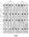
Figur 6 - Fig. 9
- eine Draufsicht auf die Ober- oder Papierseite eines dritten, der ersten Ausführungsform entsprechenden Ausführungsbeispieles jedoch in Realisierung mit wechselnder Schußfolge des Ober- und Bindeschusses.
- Fig. 1 and 2
- in the manner of sectional images, two known connection solutions according to the prior art,
- Fig. 3
- a plan view of a section of the top or paper side of the papermaker's fabric according to the invention,
- 4 and 5
- Cuts along the lines AA and BB in
FIG. 3 . - Fig. 6
- a top view of the top or paper side of a second embodiment of the paper machine wire according to the invention,
- FIGS. 7 and 8
- Cuts along the lines CC and DD in
FIG. 6 . - Fig. 9
- a plan view of the top or paper side of a third embodiment corresponding to the first embodiment, however, in realization with changing firing order of the top and binding shot.
Des weiteren ist in allen verwendeten Abbildungen die folgende Nummernzuordnung realisiert:
- 1
- Oberkette
- 2
- Oberschuß (mit Bindeschuß)
- 3'3
- Bindeschuß
- 4
- Oberschuß
- 5
- Unterkette
- 6
- Unterschuß
- 7
- Übergriff
- 8
- Untergriff
- 9
Übergriff durch Unterschuß 6
- 1
- upper chain
- 2
- Upper shot (with binding shot)
- 3'3
- binding weft
- 4
- top shot
- 5
- under chain
- 6
- deficit
- 7
- encroachment
- 8th
- undercling
- 9
- Assault by
deficit 6
Bei der bekannten im Stand der Technik nachweisbaren Lösung nach der
Bei der weiteren bekannten Lösung nach der
Im folgenden wird nunmehr die erfindungsgemäße Papiermaschinensieb-Lösung beschrieben, wobei der Einfachheit halber und des besseren Verständnisses wegen für die nachfolgenden aufgezeigten Lösungen die selben Bezugszeichen entsprechend verwendet werden, wie bei den bereits vorgestellten bekannten Lösungen.In the following, the paper machine wire solution according to the invention will now be described, wherein for the sake of simplicity and better understanding, the same reference numerals will be used accordingly for the solutions shown below, as in the known solutions already presented.
Das erste Ausführungsbeispiel eines Papiermaschinensiebes nach den
Insbesondere die
Wie sich des weiteren aus der
Die bezogen auf einen Rapport als Fünfschaftbindung ausgebildete erfinderische Bindungslösung sieht vor, dass von den Schußfäden 6 des Untergewebes vier Kettfäden 5 untergriffen und ein Kettfaden 5 in Folge übergriffen ist, wobei der jeweilige Bindeschußfaden 3 an der Stelle dieses Übergriffes 9 schräg ansteigend vom Untergewebe ins Obergewebe wechselt. Der jeweilige Bindeschußfaden 3 hat im wesentlichen den gleichen Durchmesser wie der jeweilige Schußfaden 2 des Einzelgewebes auf der Papierseite. Des weiteren sind die Kettfäden 5 sowie die Schußfäden 6 des Untergewebes, also auf der Laufseite, im Durchmesser jeweils stärker dimensioniert als die zuordenbaren Fadensysteme auf der Ober- oder Papierseite des Papiermaschinensiebes. Bezogen auf die Ober- oder Papierseite des Siebes ist in Folge der jeweilige Übergriff 7 des jeweiligen Bindefadens 3 bezogen auf einen Schußfaden 2 von drei dazwischen liegenden Kettfäden 1 getrennt, wobei an der Stelle des mittleren Kettfadens 1 dieserDreiergruppe der Bindeschußfaden 3 einen darunterliegenden Kettfaden 5 kurz vor dem Übergriff 9 durch den Unterschuß 6 untergreift. Durch die funktionale Trennung von Oberschußfäden 2 des Obergewebes und Bindeschußfäden 3 können diese aus unterschiedlichen Materialien bestehen, vorzugsweise bestehen zur Erhöhung der Querstabilität des Siebes die Oberschußfäden 2 aus einem Polyesterwerkstoff und die Bindeschußfäden 3 aus einem Polyamidwerkstoff.The inventively designed binding solution based on a repeat as a five-shaft binding provides that four
Der Oberschußfaden 4 nach der
Bei der geänderten Ausführungsform nach den
Bei der Ausführungsform nach der
Claims (5)
- A paper machine screen consisting of at least one individual fabric for the paper side and at least one individual fabric for the machine side which respectively consist of a set of weft yarns (4, 6) and warp yarns (1, 5), at least a part of the superimposed individual fabrics being interconnected via binder yarns (3), wherein the respective binder yarn (3) on the paper side engages from above (7) with warp yarns (1) of the individual fabric at those positions which on their opposite side are engaged with from below (8) by at least one adjacent weft yarn (2) of this individual fabric, and wherein in order to form the screen exactly two individual fabrics, one in the manner of an upper fabric for the paper side, one in the manner of a lower fabric for the machine side, are used, wherein the engagement from above (7) of the respective binder yarn (3) in the upper fabric in relation to a weft yarn (2) is separated by three warp yarns (1) lying therebetween, and at the position of the central warp yarn (1) of this group of three the binder weft yarn (3) engages from below with a warp yarn (5) of the lower fabric lying beneath, wherein the respective binder weft yarn (3) has substantially the same diameter as the respective weft yarn (2) of the individual fabric on the paper side, wherein the lower fabric is a four or five shaft binding, three or four warp yarns (5) are engaged from below and respectively one warp yarn (5) is engaged from above by the weft yarns (6) of the lower fabric, and the respective binder weft yarn (3) changes from the lower fabric into the upper fabric outside of or at the position of this engagement from above (9).
- The paper machine screen according to Claim 1, characterized in that as binder yarns (3) only a respective first type of binder weft yarns undertakes the joining of the individual fabrics.
- The paper machine screen according to Claim 1 or 2, characterized in that the upper fabric is formed in the manner of a plain weave and that the respective binder weft yarn (3) limits at the position of engagement from above (7) of the assignable warp yarn (1) with regard to the latter an angular dimension which is equal to the correspondingly formed angular dimension of the weft yarn (2) engaging from beneath.
- The paper machine screen according to any of Claims 1 to 3, characterized in that the engagement from above (7) of the respective binder yarn (3) on the upper side is supported by a warp yarn (1) which extends between the assignable weft yarn (2) of the upper fabric and that of the lower fabric.
- The paper machine screen according to any of Claims 1 to 4, characterized in that by the functional separation of the upper weft yarns (2) of the upper fabric and the binder weft yarns (3), these are made of different materials, preferably in order to increase the lateral stability of the screen the upper weft yarns (2) consisting of a polyester material and the binder weft yarns (3) of a polyamide material.
Applications Claiming Priority (3)
| Application Number | Priority Date | Filing Date | Title |
|---|---|---|---|
| DE10253491 | 2002-11-16 | ||
| DE10253491A DE10253491B3 (en) | 2002-11-16 | 2002-11-16 | Paper machine sieve, consists of at least one single fabric for the single paper side, binding fibres and a single fabric for the running side |
| PCT/EP2003/011776 WO2004046458A1 (en) | 2002-11-16 | 2003-10-24 | Papermaking screen |
Publications (3)
| Publication Number | Publication Date |
|---|---|
| EP1565613A1 EP1565613A1 (en) | 2005-08-24 |
| EP1565613B1 EP1565613B1 (en) | 2009-09-30 |
| EP1565613B2 true EP1565613B2 (en) | 2016-06-15 |
Family
ID=32103452
Family Applications (1)
| Application Number | Title | Priority Date | Filing Date |
|---|---|---|---|
| EP03811353.6A Expired - Lifetime EP1565613B2 (en) | 2002-11-16 | 2003-10-24 | Papermaking screen |
Country Status (9)
| Country | Link |
|---|---|
| US (1) | US7373957B2 (en) |
| EP (1) | EP1565613B2 (en) |
| JP (1) | JP4464278B2 (en) |
| CN (1) | CN1705790A (en) |
| AT (1) | ATE444393T1 (en) |
| AU (1) | AU2003276162A1 (en) |
| DE (2) | DE10253491B3 (en) |
| ES (1) | ES2333009T5 (en) |
| WO (1) | WO2004046458A1 (en) |
Families Citing this family (13)
| Publication number | Priority date | Publication date | Assignee | Title |
|---|---|---|---|---|
| KR100886468B1 (en) * | 2004-09-30 | 2009-03-04 | 아스텐존슨 인코포레이티드 | Double Layer Molding Fabric for Paper Machine |
| JP4762529B2 (en) * | 2004-11-17 | 2011-08-31 | 日本フイルコン株式会社 | Industrial two-layer fabric |
| US7445032B2 (en) * | 2005-05-05 | 2008-11-04 | Astenjohnson, Inc. | Bulk enhancing forming fabrics |
| JP4739903B2 (en) * | 2005-10-17 | 2011-08-03 | 日本フイルコン株式会社 | Industrial two-layer fabric |
| JP4383433B2 (en) * | 2006-07-21 | 2009-12-16 | 日本フエルト株式会社 | Paper fabric |
| WO2009018274A1 (en) * | 2007-07-30 | 2009-02-05 | Astenjohnson, Inc. | Warp-tied forming fabric with selective warp pair ordering |
| IT1391327B1 (en) * | 2008-08-08 | 2011-12-05 | Feltri Marone S P A | CARD MANUFACTURING FABRIC, IN PARTICULAR TO BE USED IN THE FORMATION SECTION OF A PAPER MANUFACTURING MACHINE |
| ES2391923T3 (en) * | 2009-03-20 | 2012-12-03 | Heimbach Gmbh & Co. Kg | Woven fabric band to circulate through a machine |
| DE102010017055A1 (en) * | 2010-05-21 | 2011-11-24 | Andritz Technology And Asset Management Gmbh | forming wire |
| FI20155918A7 (en) * | 2015-12-04 | 2017-06-05 | Valmet Technologies Oy | Paper machine fabric |
| CN105714450B (en) * | 2016-04-14 | 2018-05-29 | 苏州市欣楠纺织科技有限公司 | A kind of anti-slippage sportswear lining of weaving polyester and its method for weaving |
| FI20206371A1 (en) * | 2020-12-23 | 2022-06-24 | Valmet Technologies Inc | Industrial textile |
| JP7515443B2 (en) * | 2021-07-21 | 2024-07-12 | 日本フイルコン株式会社 | Industrial Fabrics |
Citations (2)
| Publication number | Priority date | Publication date | Assignee | Title |
|---|---|---|---|---|
| US4729412A (en) † | 1983-02-23 | 1988-03-08 | Nordiskafilt Ab | Forming fabric of double-layer type |
| US5482567A (en) † | 1994-12-06 | 1996-01-09 | Huyck Licensco, Inc. | Multilayer forming fabric |
Family Cites Families (17)
| Publication number | Priority date | Publication date | Assignee | Title |
|---|---|---|---|---|
| US4705601A (en) * | 1987-02-05 | 1987-11-10 | B.I. Industries, Inc. | Multi-ply paper forming fabric with ovate warp yarns in lowermost ply |
| US5238536A (en) * | 1991-06-26 | 1993-08-24 | Huyck Licensco, Inc. | Multilayer forming fabric |
| DE4229828C2 (en) | 1992-09-07 | 1996-07-04 | Kufferath Andreas Gmbh | Paper machine screen in the form of a composite fabric |
| US5518042A (en) * | 1994-09-16 | 1996-05-21 | Huyck Licensco, Inc. | Papermaker's forming fabric with additional cross machine direction locator and fiber supporting yarns |
| GB9604602D0 (en) * | 1996-03-04 | 1996-05-01 | Jwi Ltd | Composite papermaking fabric with paired weft binder yarns |
| US5967195A (en) * | 1997-08-01 | 1999-10-19 | Weavexx Corporation | Multi-layer forming fabric with stitching yarn pairs integrated into papermaking surface |
| US5881764A (en) * | 1997-08-01 | 1999-03-16 | Weavexx Corporation | Multi-layer forming fabric with stitching yarn pairs integrated into papermaking surface |
| GB2351505A (en) * | 1999-06-29 | 2001-01-03 | Jwi Ltd | Two-layer woven fabric for papermaking machines |
| GB0005344D0 (en) * | 2000-03-06 | 2000-04-26 | Stone Richard | Forming fabric with machine side layer weft binder yarns |
| FI108551B (en) * | 2000-06-26 | 2002-02-15 | Tamfelt Oyj Abp | A paper machine fabric |
| DE10030650C1 (en) * | 2000-06-29 | 2002-05-29 | Kufferath Andreas Gmbh | papermaker |
| DE10123204C2 (en) * | 2001-05-12 | 2003-03-27 | Kufferath Andreas Gmbh | papermaker |
| US6883556B2 (en) * | 2002-12-30 | 2005-04-26 | Albany International Corp. | Double cross parallel binder fabric |
| US6905574B2 (en) * | 2003-04-18 | 2005-06-14 | Albany International Corp. | Multi-layer forming fabric with two warp systems bound together with a triplet of binder yarns |
| US6926043B2 (en) * | 2003-05-30 | 2005-08-09 | Voith Fabrics Gmbh & Co. Kg | Forming fabrics |
| US6978809B2 (en) * | 2003-09-29 | 2005-12-27 | Voith Fabrics | Composite papermaking fabric |
| US7007722B2 (en) * | 2003-11-17 | 2006-03-07 | Voith Paper Patent Gmbh | Forming fabric |
-
2002
- 2002-11-16 DE DE10253491A patent/DE10253491B3/en not_active Expired - Lifetime
-
2003
- 2003-10-24 EP EP03811353.6A patent/EP1565613B2/en not_active Expired - Lifetime
- 2003-10-24 AT AT03811353T patent/ATE444393T1/en active
- 2003-10-24 US US10/530,724 patent/US7373957B2/en not_active Expired - Lifetime
- 2003-10-24 ES ES03811353.6T patent/ES2333009T5/en not_active Expired - Lifetime
- 2003-10-24 CN CNA2003801016789A patent/CN1705790A/en active Pending
- 2003-10-24 JP JP2004552491A patent/JP4464278B2/en not_active Expired - Lifetime
- 2003-10-24 WO PCT/EP2003/011776 patent/WO2004046458A1/en not_active Ceased
- 2003-10-24 DE DE50311978T patent/DE50311978D1/en not_active Expired - Lifetime
- 2003-10-24 AU AU2003276162A patent/AU2003276162A1/en not_active Abandoned
Patent Citations (2)
| Publication number | Priority date | Publication date | Assignee | Title |
|---|---|---|---|---|
| US4729412A (en) † | 1983-02-23 | 1988-03-08 | Nordiskafilt Ab | Forming fabric of double-layer type |
| US5482567A (en) † | 1994-12-06 | 1996-01-09 | Huyck Licensco, Inc. | Multilayer forming fabric |
Also Published As
| Publication number | Publication date |
|---|---|
| DE50311978D1 (en) | 2009-11-12 |
| DE10253491B3 (en) | 2004-05-13 |
| ATE444393T1 (en) | 2009-10-15 |
| AU2003276162A1 (en) | 2004-06-15 |
| US7373957B2 (en) | 2008-05-20 |
| ES2333009T5 (en) | 2016-09-26 |
| US20060162804A1 (en) | 2006-07-27 |
| EP1565613A1 (en) | 2005-08-24 |
| ES2333009T3 (en) | 2010-02-16 |
| EP1565613B1 (en) | 2009-09-30 |
| WO2004046458A1 (en) | 2004-06-03 |
| JP2006506546A (en) | 2006-02-23 |
| CN1705790A (en) | 2005-12-07 |
| JP4464278B2 (en) | 2010-05-19 |
Similar Documents
| Publication | Publication Date | Title |
|---|---|---|
| EP1294981B2 (en) | Paper making wire cloth | |
| DE3635632A1 (en) | COVER FOR THE SHEET FORMING PART OF A PAPER MACHINE | |
| EP2470716B1 (en) | Forming fabric | |
| EP1565613B2 (en) | Papermaking screen | |
| DE102013108399B3 (en) | PAPER MACHINERY, WHICH HAS TREAD PANELS WITH DIFFERENT FLOATING LENGTH | |
| EP1387902B1 (en) | Wire cloth for paper-making machine | |
| EP2898144B1 (en) | Paper machine wire | |
| EP2764157B1 (en) | Papermaking fabric | |
| EP1013820B1 (en) | Composite papermaking fabric having three or more layers | |
| EP2067895B1 (en) | Forming fabric for use in a paper making machine | |
| WO2010049304A1 (en) | Forming fabric | |
| EP1798335B1 (en) | Papermaking fabric | |
| EP2205791A1 (en) | Forming screen | |
| EP0889160A1 (en) | Screencloth for papermaking machine | |
| EP1977037B1 (en) | Papermachine fabric | |
| DE102004016640B3 (en) | Fourdrinier, especially for a papermaking machine to produce toilet paper, is of two bonded woven layers with an increased weft count in the upper layer | |
| EP2004903B1 (en) | Upper side, in particular paper side, for a paper machine forming fabric and paper machine forming fabric | |
| DE102011083192A1 (en) | Paper making wire cloth, particularly forming fabric for sheet forming zone of paper or tissue machine in paper manufacturing industry, has lower float thread provided in lower repeat unit that forms machine-sided thread longitudinal floats | |
| EP1798334A1 (en) | Papermaking fabric |
Legal Events
| Date | Code | Title | Description |
|---|---|---|---|
| PUAI | Public reference made under article 153(3) epc to a published international application that has entered the european phase |
Free format text: ORIGINAL CODE: 0009012 |
|
| 17P | Request for examination filed |
Effective date: 20050210 |
|
| AK | Designated contracting states |
Kind code of ref document: A1 Designated state(s): AT BE BG CH CY CZ DE DK EE ES FI FR GB GR HU IE IT LI LU MC NL PT RO SE SI SK TR |
|
| AX | Request for extension of the european patent |
Extension state: AL LT LV MK |
|
| DAX | Request for extension of the european patent (deleted) | ||
| 17Q | First examination report despatched |
Effective date: 20080619 |
|
| GRAP | Despatch of communication of intention to grant a patent |
Free format text: ORIGINAL CODE: EPIDOSNIGR1 |
|
| RAP1 | Party data changed (applicant data changed or rights of an application transferred) |
Owner name: ANDRITZ TECHNOLOGY AND ASSET MANAGEMENT GMBH |
|
| GRAS | Grant fee paid |
Free format text: ORIGINAL CODE: EPIDOSNIGR3 |
|
| GRAA | (expected) grant |
Free format text: ORIGINAL CODE: 0009210 |
|
| AK | Designated contracting states |
Kind code of ref document: B1 Designated state(s): AT BE BG CH CY CZ DE DK EE ES FI FR GB GR HU IE IT LI LU MC NL PT RO SE SI SK TR |
|
| REG | Reference to a national code |
Ref country code: GB Ref legal event code: FG4D Free format text: NOT ENGLISH Ref country code: CH Ref legal event code: EP |
|
| REG | Reference to a national code |
Ref country code: IE Ref legal event code: FG4D |
|
| REF | Corresponds to: |
Ref document number: 50311978 Country of ref document: DE Date of ref document: 20091112 Kind code of ref document: P |
|
| REG | Reference to a national code |
Ref country code: SE Ref legal event code: TRGR |
|
| REG | Reference to a national code |
Ref country code: ES Ref legal event code: FG2A Ref document number: 2333009 Country of ref document: ES Kind code of ref document: T3 |
|
| PG25 | Lapsed in a contracting state [announced via postgrant information from national office to epo] |
Ref country code: SI Free format text: LAPSE BECAUSE OF FAILURE TO SUBMIT A TRANSLATION OF THE DESCRIPTION OR TO PAY THE FEE WITHIN THE PRESCRIBED TIME-LIMIT Effective date: 20090930 |
|
| NLV1 | Nl: lapsed or annulled due to failure to fulfill the requirements of art. 29p and 29m of the patents act | ||
| PG25 | Lapsed in a contracting state [announced via postgrant information from national office to epo] |
Ref country code: PT Free format text: LAPSE BECAUSE OF FAILURE TO SUBMIT A TRANSLATION OF THE DESCRIPTION OR TO PAY THE FEE WITHIN THE PRESCRIBED TIME-LIMIT Effective date: 20100201 Ref country code: RO Free format text: LAPSE BECAUSE OF FAILURE TO SUBMIT A TRANSLATION OF THE DESCRIPTION OR TO PAY THE FEE WITHIN THE PRESCRIBED TIME-LIMIT Effective date: 20090930 Ref country code: EE Free format text: LAPSE BECAUSE OF FAILURE TO SUBMIT A TRANSLATION OF THE DESCRIPTION OR TO PAY THE FEE WITHIN THE PRESCRIBED TIME-LIMIT Effective date: 20090930 |
|
| REG | Reference to a national code |
Ref country code: IE Ref legal event code: FD4D |
|
| PG25 | Lapsed in a contracting state [announced via postgrant information from national office to epo] |
Ref country code: MC Free format text: LAPSE BECAUSE OF NON-PAYMENT OF DUE FEES Effective date: 20091031 Ref country code: CY Free format text: LAPSE BECAUSE OF FAILURE TO SUBMIT A TRANSLATION OF THE DESCRIPTION OR TO PAY THE FEE WITHIN THE PRESCRIBED TIME-LIMIT Effective date: 20090930 Ref country code: SK Free format text: LAPSE BECAUSE OF FAILURE TO SUBMIT A TRANSLATION OF THE DESCRIPTION OR TO PAY THE FEE WITHIN THE PRESCRIBED TIME-LIMIT Effective date: 20090930 |
|
| PLBI | Opposition filed |
Free format text: ORIGINAL CODE: 0009260 |
|
| 26 | Opposition filed |
Opponent name: HEIMBACH GMBH & CO. KG Effective date: 20100618 |
|
| PG25 | Lapsed in a contracting state [announced via postgrant information from national office to epo] |
Ref country code: NL Free format text: LAPSE BECAUSE OF FAILURE TO SUBMIT A TRANSLATION OF THE DESCRIPTION OR TO PAY THE FEE WITHIN THE PRESCRIBED TIME-LIMIT Effective date: 20090930 Ref country code: IE Free format text: LAPSE BECAUSE OF FAILURE TO SUBMIT A TRANSLATION OF THE DESCRIPTION OR TO PAY THE FEE WITHIN THE PRESCRIBED TIME-LIMIT Effective date: 20090930 Ref country code: DK Free format text: LAPSE BECAUSE OF FAILURE TO SUBMIT A TRANSLATION OF THE DESCRIPTION OR TO PAY THE FEE WITHIN THE PRESCRIBED TIME-LIMIT Effective date: 20090930 |
|
| PLAX | Notice of opposition and request to file observation + time limit sent |
Free format text: ORIGINAL CODE: EPIDOSNOBS2 |
|
| PG25 | Lapsed in a contracting state [announced via postgrant information from national office to epo] |
Ref country code: GR Free format text: LAPSE BECAUSE OF FAILURE TO SUBMIT A TRANSLATION OF THE DESCRIPTION OR TO PAY THE FEE WITHIN THE PRESCRIBED TIME-LIMIT Effective date: 20091231 |
|
| PLAF | Information modified related to communication of a notice of opposition and request to file observations + time limit |
Free format text: ORIGINAL CODE: EPIDOSCOBS2 |
|
| PLBB | Reply of patent proprietor to notice(s) of opposition received |
Free format text: ORIGINAL CODE: EPIDOSNOBS3 |
|
| PG25 | Lapsed in a contracting state [announced via postgrant information from national office to epo] |
Ref country code: BG Free format text: LAPSE BECAUSE OF FAILURE TO SUBMIT A TRANSLATION OF THE DESCRIPTION OR TO PAY THE FEE WITHIN THE PRESCRIBED TIME-LIMIT Effective date: 20091031 |
|
| PG25 | Lapsed in a contracting state [announced via postgrant information from national office to epo] |
Ref country code: LU Free format text: LAPSE BECAUSE OF NON-PAYMENT OF DUE FEES Effective date: 20091024 |
|
| PG25 | Lapsed in a contracting state [announced via postgrant information from national office to epo] |
Ref country code: HU Free format text: LAPSE BECAUSE OF FAILURE TO SUBMIT A TRANSLATION OF THE DESCRIPTION OR TO PAY THE FEE WITHIN THE PRESCRIBED TIME-LIMIT Effective date: 20100401 |
|
| PG25 | Lapsed in a contracting state [announced via postgrant information from national office to epo] |
Ref country code: TR Free format text: LAPSE BECAUSE OF FAILURE TO SUBMIT A TRANSLATION OF THE DESCRIPTION OR TO PAY THE FEE WITHIN THE PRESCRIBED TIME-LIMIT Effective date: 20090930 |
|
| RIC2 | Information provided on ipc code assigned after grant |
Ipc: D21F 1/00 20060101AFI20150617BHEP |
|
| APBM | Appeal reference recorded |
Free format text: ORIGINAL CODE: EPIDOSNREFNO |
|
| APBP | Date of receipt of notice of appeal recorded |
Free format text: ORIGINAL CODE: EPIDOSNNOA2O |
|
| APAH | Appeal reference modified |
Free format text: ORIGINAL CODE: EPIDOSCREFNO |
|
| REG | Reference to a national code |
Ref country code: FR Ref legal event code: PLFP Year of fee payment: 13 |
|
| APBU | Appeal procedure closed |
Free format text: ORIGINAL CODE: EPIDOSNNOA9O |
|
| PUAH | Patent maintained in amended form |
Free format text: ORIGINAL CODE: 0009272 |
|
| STAA | Information on the status of an ep patent application or granted ep patent |
Free format text: STATUS: PATENT MAINTAINED AS AMENDED |
|
| 27A | Patent maintained in amended form |
Effective date: 20160615 |
|
| AK | Designated contracting states |
Kind code of ref document: B2 Designated state(s): AT BE BG CH CY CZ DE DK EE ES FI FR GB GR HU IE IT LI LU MC NL PT RO SE SI SK TR |
|
| REG | Reference to a national code |
Ref country code: CH Ref legal event code: AELC Ref country code: DE Ref legal event code: R102 Ref document number: 50311978 Country of ref document: DE |
|
| REG | Reference to a national code |
Ref country code: ES Ref legal event code: DC2A Ref document number: 2333009 Country of ref document: ES Kind code of ref document: T5 Effective date: 20160926 |
|
| REG | Reference to a national code |
Ref country code: SE Ref legal event code: RPEO |
|
| REG | Reference to a national code |
Ref country code: FR Ref legal event code: PLFP Year of fee payment: 14 |
|
| REG | Reference to a national code |
Ref country code: FR Ref legal event code: PLFP Year of fee payment: 15 |
|
| REG | Reference to a national code |
Ref country code: FR Ref legal event code: PLFP Year of fee payment: 16 |
|
| PGFP | Annual fee paid to national office [announced via postgrant information from national office to epo] |
Ref country code: CZ Payment date: 20190925 Year of fee payment: 17 |
|
| PGFP | Annual fee paid to national office [announced via postgrant information from national office to epo] |
Ref country code: DE Payment date: 20191021 Year of fee payment: 17 |
|
| PGFP | Annual fee paid to national office [announced via postgrant information from national office to epo] |
Ref country code: ES Payment date: 20191122 Year of fee payment: 17 Ref country code: BE Payment date: 20191021 Year of fee payment: 17 |
|
| PGFP | Annual fee paid to national office [announced via postgrant information from national office to epo] |
Ref country code: CH Payment date: 20191021 Year of fee payment: 17 |
|
| REG | Reference to a national code |
Ref country code: DE Ref legal event code: R119 Ref document number: 50311978 Country of ref document: DE |
|
| REG | Reference to a national code |
Ref country code: CH Ref legal event code: PL |
|
| REG | Reference to a national code |
Ref country code: BE Ref legal event code: MM Effective date: 20201031 |
|
| PG25 | Lapsed in a contracting state [announced via postgrant information from national office to epo] |
Ref country code: DE Free format text: LAPSE BECAUSE OF NON-PAYMENT OF DUE FEES Effective date: 20210501 Ref country code: CZ Free format text: LAPSE BECAUSE OF NON-PAYMENT OF DUE FEES Effective date: 20201024 |
|
| PG25 | Lapsed in a contracting state [announced via postgrant information from national office to epo] |
Ref country code: CH Free format text: LAPSE BECAUSE OF NON-PAYMENT OF DUE FEES Effective date: 20201031 Ref country code: BE Free format text: LAPSE BECAUSE OF NON-PAYMENT OF DUE FEES Effective date: 20201031 Ref country code: LI Free format text: LAPSE BECAUSE OF NON-PAYMENT OF DUE FEES Effective date: 20201031 |
|
| REG | Reference to a national code |
Ref country code: ES Ref legal event code: FD2A Effective date: 20220128 |
|
| PG25 | Lapsed in a contracting state [announced via postgrant information from national office to epo] |
Ref country code: ES Free format text: LAPSE BECAUSE OF NON-PAYMENT OF DUE FEES Effective date: 20201025 |
|
| PGFP | Annual fee paid to national office [announced via postgrant information from national office to epo] |
Ref country code: FR Payment date: 20221028 Year of fee payment: 20 |
|
| PGFP | Annual fee paid to national office [announced via postgrant information from national office to epo] |
Ref country code: SE Payment date: 20221019 Year of fee payment: 20 Ref country code: IT Payment date: 20221026 Year of fee payment: 20 Ref country code: GB Payment date: 20221019 Year of fee payment: 20 Ref country code: FI Payment date: 20221020 Year of fee payment: 20 Ref country code: AT Payment date: 20221020 Year of fee payment: 20 |
|
| P01 | Opt-out of the competence of the unified patent court (upc) registered |
Effective date: 20230428 |
|
| REG | Reference to a national code |
Ref country code: GB Ref legal event code: PE20 Expiry date: 20231023 |
|
| REG | Reference to a national code |
Ref country code: SE Ref legal event code: EUG |
|
| REG | Reference to a national code |
Ref country code: AT Ref legal event code: MK07 Ref document number: 444393 Country of ref document: AT Kind code of ref document: T Effective date: 20231024 |
|
| PG25 | Lapsed in a contracting state [announced via postgrant information from national office to epo] |
Ref country code: GB Free format text: LAPSE BECAUSE OF EXPIRATION OF PROTECTION Effective date: 20231023 |
|
| PG25 | Lapsed in a contracting state [announced via postgrant information from national office to epo] |
Ref country code: GB Free format text: LAPSE BECAUSE OF EXPIRATION OF PROTECTION Effective date: 20231023 |