EP1565608B1 - Washing machine, conductivity sensor in washing machine, and controlling method of the same - Google Patents
Washing machine, conductivity sensor in washing machine, and controlling method of the same Download PDFInfo
- Publication number
- EP1565608B1 EP1565608B1 EP03774339A EP03774339A EP1565608B1 EP 1565608 B1 EP1565608 B1 EP 1565608B1 EP 03774339 A EP03774339 A EP 03774339A EP 03774339 A EP03774339 A EP 03774339A EP 1565608 B1 EP1565608 B1 EP 1565608B1
- Authority
- EP
- European Patent Office
- Prior art keywords
- washing machine
- electrodes
- machine according
- protection member
- washing
- Prior art date
- Legal status (The legal status is an assumption and is not a legal conclusion. Google has not performed a legal analysis and makes no representation as to the accuracy of the status listed.)
- Expired - Lifetime
Links
- 238000005406 washing Methods 0.000 title claims abstract description 159
- 238000000034 method Methods 0.000 title abstract description 18
- XLYOFNOQVPJJNP-UHFFFAOYSA-N water Substances O XLYOFNOQVPJJNP-UHFFFAOYSA-N 0.000 claims abstract description 91
- 238000007789 sealing Methods 0.000 claims description 37
- 239000000126 substance Substances 0.000 claims description 29
- 239000007788 liquid Substances 0.000 claims description 6
- 238000002347 injection Methods 0.000 claims description 3
- 239000007924 injection Substances 0.000 claims description 3
- 229920005989 resin Polymers 0.000 claims 2
- 239000011347 resin Substances 0.000 claims 2
- 239000003822 epoxy resin Substances 0.000 claims 1
- 229920000647 polyepoxide Polymers 0.000 claims 1
- 238000010276 construction Methods 0.000 abstract description 26
- 238000009434 installation Methods 0.000 abstract description 19
- 239000003599 detergent Substances 0.000 description 17
- 230000008878 coupling Effects 0.000 description 13
- 238000010168 coupling process Methods 0.000 description 13
- 238000005859 coupling reaction Methods 0.000 description 13
- 239000000565 sealant Substances 0.000 description 9
- 230000000694 effects Effects 0.000 description 5
- 239000004020 conductor Substances 0.000 description 4
- 150000002500 ions Chemical class 0.000 description 4
- 238000001556 precipitation Methods 0.000 description 4
- 238000003780 insertion Methods 0.000 description 3
- 230000037431 insertion Effects 0.000 description 3
- 230000033001 locomotion Effects 0.000 description 3
- 239000000463 material Substances 0.000 description 3
- 239000000725 suspension Substances 0.000 description 3
- 101001139126 Homo sapiens Krueppel-like factor 6 Proteins 0.000 description 2
- XEEYBQQBJWHFJM-UHFFFAOYSA-N Iron Chemical compound [Fe] XEEYBQQBJWHFJM-UHFFFAOYSA-N 0.000 description 2
- 230000000881 depressing effect Effects 0.000 description 2
- 230000004927 fusion Effects 0.000 description 2
- OYPRJOBELJOOCE-UHFFFAOYSA-N Calcium Chemical compound [Ca] OYPRJOBELJOOCE-UHFFFAOYSA-N 0.000 description 1
- BHPQYMZQTOCNFJ-UHFFFAOYSA-N Calcium cation Chemical compound [Ca+2] BHPQYMZQTOCNFJ-UHFFFAOYSA-N 0.000 description 1
- RYGMFSIKBFXOCR-UHFFFAOYSA-N Copper Chemical compound [Cu] RYGMFSIKBFXOCR-UHFFFAOYSA-N 0.000 description 1
- 239000004593 Epoxy Substances 0.000 description 1
- 101000710013 Homo sapiens Reversion-inducing cysteine-rich protein with Kazal motifs Proteins 0.000 description 1
- 101000661807 Homo sapiens Suppressor of tumorigenicity 14 protein Proteins 0.000 description 1
- FYYHWMGAXLPEAU-UHFFFAOYSA-N Magnesium Chemical compound [Mg] FYYHWMGAXLPEAU-UHFFFAOYSA-N 0.000 description 1
- JLVVSXFLKOJNIY-UHFFFAOYSA-N Magnesium ion Chemical compound [Mg+2] JLVVSXFLKOJNIY-UHFFFAOYSA-N 0.000 description 1
- 230000005540 biological transmission Effects 0.000 description 1
- 230000015572 biosynthetic process Effects 0.000 description 1
- 229910052791 calcium Inorganic materials 0.000 description 1
- 239000011575 calcium Substances 0.000 description 1
- 229910001424 calcium ion Inorganic materials 0.000 description 1
- 238000004140 cleaning Methods 0.000 description 1
- 229910052802 copper Inorganic materials 0.000 description 1
- 239000010949 copper Substances 0.000 description 1
- 230000007797 corrosion Effects 0.000 description 1
- 238000005260 corrosion Methods 0.000 description 1
- 230000003247 decreasing effect Effects 0.000 description 1
- 238000007599 discharging Methods 0.000 description 1
- 230000005611 electricity Effects 0.000 description 1
- 238000005755 formation reaction Methods 0.000 description 1
- 239000008235 industrial water Substances 0.000 description 1
- 108090000237 interleukin-24 Proteins 0.000 description 1
- 229910052742 iron Inorganic materials 0.000 description 1
- 239000011344 liquid material Substances 0.000 description 1
- 229910052749 magnesium Inorganic materials 0.000 description 1
- 239000011777 magnesium Substances 0.000 description 1
- 229910001425 magnesium ion Inorganic materials 0.000 description 1
- 238000005259 measurement Methods 0.000 description 1
- 239000000615 nonconductor Substances 0.000 description 1
- 238000006479 redox reaction Methods 0.000 description 1
- 238000005096 rolling process Methods 0.000 description 1
- 230000008054 signal transmission Effects 0.000 description 1
- 229910052712 strontium Inorganic materials 0.000 description 1
- CIOAGBVUUVVLOB-UHFFFAOYSA-N strontium atom Chemical compound [Sr] CIOAGBVUUVVLOB-UHFFFAOYSA-N 0.000 description 1
- 239000002351 wastewater Substances 0.000 description 1
Images


Classifications
-
- G—PHYSICS
- G01—MEASURING; TESTING
- G01N—INVESTIGATING OR ANALYSING MATERIALS BY DETERMINING THEIR CHEMICAL OR PHYSICAL PROPERTIES
- G01N27/00—Investigating or analysing materials by the use of electric, electrochemical, or magnetic means
- G01N27/02—Investigating or analysing materials by the use of electric, electrochemical, or magnetic means by investigating impedance
- G01N27/04—Investigating or analysing materials by the use of electric, electrochemical, or magnetic means by investigating impedance by investigating resistance
- G01N27/06—Investigating or analysing materials by the use of electric, electrochemical, or magnetic means by investigating impedance by investigating resistance of a liquid
- G01N27/08—Investigating or analysing materials by the use of electric, electrochemical, or magnetic means by investigating impedance by investigating resistance of a liquid which is flowing continuously
- G01N27/10—Investigation or analysis specially adapted for controlling or monitoring operations or for signalling
-
- D—TEXTILES; PAPER
- D06—TREATMENT OF TEXTILES OR THE LIKE; LAUNDERING; FLEXIBLE MATERIALS NOT OTHERWISE PROVIDED FOR
- D06F—LAUNDERING, DRYING, IRONING, PRESSING OR FOLDING TEXTILE ARTICLES
- D06F33/00—Control of operations performed in washing machines or washer-dryers
- D06F33/30—Control of washing machines characterised by the purpose or target of the control
- D06F33/32—Control of operational steps, e.g. optimisation or improvement of operational steps depending on the condition of the laundry
-
- D—TEXTILES; PAPER
- D06—TREATMENT OF TEXTILES OR THE LIKE; LAUNDERING; FLEXIBLE MATERIALS NOT OTHERWISE PROVIDED FOR
- D06F—LAUNDERING, DRYING, IRONING, PRESSING OR FOLDING TEXTILE ARTICLES
- D06F34/00—Details of control systems for washing machines, washer-dryers or laundry dryers
- D06F34/14—Arrangements for detecting or measuring specific parameters
- D06F34/22—Condition of the washing liquid, e.g. turbidity
-
- H—ELECTRICITY
- H01—ELECTRIC ELEMENTS
- H01R—ELECTRICALLY-CONDUCTIVE CONNECTIONS; STRUCTURAL ASSOCIATIONS OF A PLURALITY OF MUTUALLY-INSULATED ELECTRICAL CONNECTING ELEMENTS; COUPLING DEVICES; CURRENT COLLECTORS
- H01R13/00—Details of coupling devices of the kinds covered by groups H01R12/70 or H01R24/00 - H01R33/00
- H01R13/46—Bases; Cases
- H01R13/52—Dustproof, splashproof, drip-proof, waterproof, or flameproof cases
- H01R13/521—Sealing between contact members and housing, e.g. sealing insert
-
- D—TEXTILES; PAPER
- D06—TREATMENT OF TEXTILES OR THE LIKE; LAUNDERING; FLEXIBLE MATERIALS NOT OTHERWISE PROVIDED FOR
- D06F—LAUNDERING, DRYING, IRONING, PRESSING OR FOLDING TEXTILE ARTICLES
- D06F2103/00—Parameters monitored or detected for the control of domestic laundry washing machines, washer-dryers or laundry dryers
- D06F2103/20—Washing liquid condition, e.g. turbidity
-
- D—TEXTILES; PAPER
- D06—TREATMENT OF TEXTILES OR THE LIKE; LAUNDERING; FLEXIBLE MATERIALS NOT OTHERWISE PROVIDED FOR
- D06F—LAUNDERING, DRYING, IRONING, PRESSING OR FOLDING TEXTILE ARTICLES
- D06F2105/00—Systems or parameters controlled or affected by the control systems of washing machines, washer-dryers or laundry dryers
- D06F2105/52—Changing sequence of operational steps; Carrying out additional operational steps; Modifying operational steps, e.g. by extending duration of steps
-
- D—TEXTILES; PAPER
- D06—TREATMENT OF TEXTILES OR THE LIKE; LAUNDERING; FLEXIBLE MATERIALS NOT OTHERWISE PROVIDED FOR
- D06F—LAUNDERING, DRYING, IRONING, PRESSING OR FOLDING TEXTILE ARTICLES
- D06F34/00—Details of control systems for washing machines, washer-dryers or laundry dryers
- D06F34/14—Arrangements for detecting or measuring specific parameters
- D06F34/22—Condition of the washing liquid, e.g. turbidity
- D06F34/24—Liquid temperature
Definitions
- the present invention relates to a washing machine capable of measuring a hardness of a washing water.
- a washing machine is known for example from JP-A-06, 233, 892 .
- various sensors are installed in a washing machine to sense several washing conditions necessary for a washing operation.
- the washing machine is appropriately driven according to the sensed washing conditions in order to obtain the maximum washing effect.
- sensors of a conventional washing machine a sensor for sensing an amount of washing water received in a washing tub and a sensor for measuring a water temperature in order to boil the laundry have been proposed and used.
- the water hardness is a term that represents a degree of a water strength.
- Materials determining the hardness are calcium, magnesium, iron, strontium, and the like.
- a detergent is not dissolved well due to magnesium ions or calcium ions contained in the water, so that a cleaning capacity of the detergent is degraded. Accordingly, the water having a high hardness is not suitable for domestic water or industrial water.
- the related art has not proposed a method for adjusting an amount of detergent and water in the washing machine according to the hardness of the washing water.
- the equal method of inputting detergent and water is applied at every area, which is one of factors that degrade the washing efficiency.
- an equal amount of detergent and water is used while the hardness of the washing water is ignored. This is an important factor that degrades the washing efficiency.
- the present invention is directed to a washing machine that substantially obviates the problems caused by limitations and disadvantage of the conventional one.
- One object of the present invention is to provide a washing machine in which the optimum washing efficiency is obtained by properly changing a washing method according to a hardness of a washing water.
- Another object of the present invention is to provide a washing machine, in which the reliability is improved by using a measured conductivity of a washing water as various indexes of an operation of the washing machine.
- a washing machine includes the combined features of claim 1.
- the reliability in the operation of the washing machine can be improved.
- the washing efficiency can be improved by adjusting an amount of detergent and washing water according to the hardness of the washing water, which is sensed by the conductivity sensor.
- the conductivity sensor is stably operated, thereby preventing an erroneous operation of the conductivity sensor, which may be caused by leakage of water and foreign substance.
- FIGs. 1 to 3 A first embodiment of the present invention will be described in detail with reference to FIGs. 1 to 3 .
- FIG. 1 is a sectional view of a washing machine according to a first embodiment of the present invention.
- the washing machine includes: a cabinet 1 forming an outer shell; an outer tub 2 fixedly suspended inside the cabinet 1 by a plurality of suspension members 10, for containing a washing water; a damper 14 formed on a lower portion of the suspension member 10 to attenuate a vibration of the outer tub 2; an inner tub 3 rotatably installed inside the outer tub 2 to receive a laundry and a washing water supplied through a supply valve; a pulsator 7 rotatably installed in a lower portion of the inner tub 3 to agitate a water current of the washing water; a drive motor 4 driven by an external power; a drive shaft 5 disposed at a central portion of the drive motor 4; a clutch 6 installed in a lower portion of the outer tub 2 to selectively rotate the inner tub 3 or the pulsator 7; a manipulation/control unit 8 for controlling a washing cycle and operation of the washing machine; a drain port 15 installed in a lower portion of the outer tub 2 to discharge the washing water from the
- a microprocessor and a digital storage media are installed inside the manipulation/control unit 8 to control an overall operation of the washing machine.
- a laundry is put in the tub through the door 9 and the washing machine begins to operate under a control of the manipulation/control unit 8.
- a power applied through the motor 4, the drive shaft 5 and the clutch 6 in sequence is supplied to the pulsator 7, such that the pulsator 7 rotates.
- the pulsator 7 rotates the washing water and the laundry and causes a friction therebetween. In this manner, a washing operation is performed. After the washing operation is completed, the wastewater is discharged through the drain port 15.
- an overall cycle of the washing machine is controlled through the manipulation/control unit 8.
- a predetermined program stored in the storage media controls the motor 4, a supply/drain value and the clutch 6, such that an overall operation of the washing machine is controlled properly.
- the damper 14 is connected to the cabinet 1 through the suspension member 10.
- the damper 14 attenuates a vibration of the outer tub 2 to thereby reduce a vibration and movement of the body of the washing machine.
- the washing water is introduced into the pneumatic chamber 11 through the inlet/outlet port 16.
- the conductivity sensor 13 measures a conductivity of the washing water introduced into the pneumatic chamber 11, and a hardness of the washing water is sensed using the measured conductivity with reference to a predetermined table.
- the table can be stored in the digital storage media and can be read/controlled by the microprocessor.
- the digital storage media and the microprocessor are installed inside the manipulation/control unit 8.
- a water level inside the pneumatic chamber 11 also rises. At this time, since the inside of the pneumatic chamber 11 is in a hermetically sealed state, the washing water is not discharged. Therefore, as the washing water is introduced into the outer tub 2, the internal pressure of the pneumatic chamber 11 increases. The water level of the washing water introduced inside the outer tub 2 can be measured using a pneumatic of the pneumatic chamber 11.
- a hydraulic pressure in a lower portion of the pneumatic chamber 11 is a sum of an air pressure in the inside of the pneumatic chamber 11 and a hydraulic pressure caused due to a water level of the pneumatic chamber 11.
- the hydraulic pressure in the lower portion of the pneumatic chamber 11 is identical to a total hydraulic pressure in the inside of the outer tub 2. Therefore, the water level of the outer tub 2 can be sensed using the air pressure in the inside of the pneumatic chamber 11. In other words, as the water level of the outer tub 2 rises higher, the air pressure in the inside of the pneumatic chamber 11 increases higher.
- the water level of the outer tub 2 can be sensed by inversely using a linear relationship of the increasing hydraulic pressure.
- FIG. 2 is an enlarged sectional view of the portion "A" shown in FIG. 1
- FIG. 3 is a perspective view of a conductivity sensor.
- the conductivity sensor 13 includes: a pair of electrodes 91 formed of a conductive material in a bar shape; an upper protection member 21 for supporting and protecting an upper portion of the electrodes 91; a lower protection member 31 for supporting and protecting a lower portion of the electrodes 91; a sealing member 41 filled inside the protection members 21 and 31; an upper fixing portion 211 in which the upper protection member 21 and the chamber housing 17 are coupled to each other; a lower fixing portion 311 in which the upper protection member 21 and the lower protection member 31 are coupled to each other; and a connector 51 extended downward from the lower protection member 31.
- the conductivity sensor 13 is insertedly installed in an opening of a lower portion of the chamber housing 17 and coupled with the chamber housing 17 at the upper fixing portion 211.
- the upper fixing portion 211 can be fixed in any manner, for example, a fusion, an adhesion, a latching structure having a sealing member intervened therein.
- the lower fixing portion 311 can also be fixed by a fusion, an adhesion, a latching structure having a sealing member intervened therein.
- the pair of the electrodes 91 are formed, and a protruded upper end portion of each electrode 91 protruded inside the pneumatic chamber 11 keeps in contact with the washing water.
- the electrodes 91 must be made of material, such as stainless or copper, which has a high conductivity and a high corrosion resistance.
- the electrodes 91 one flows an electric current into the washing water and the other senses an amount of electric current flowing into the washing water. In this manner, the quantity of ions contained in the washing water can be sensed according to the amount of the electric current and the hardness of the washing water can be measured according to the sensed quantity of ions.
- the sealing member 41 can be made of rubber or epoxy material.
- the sealing member 41 is interposed among the protection members 21 and 31 and the electrodes 91 and prevents any leakage of the washing water contained in the pneumatic chamber 11.
- the sealing member 41 can be formed by filling an inner space of the upper protection member 21 with a liquid material and then compressing it by a thrust of the lower protection member 31.
- a receptacle in which a predetermined terminal is formed is inserted into the connector 51 to thereby transfer the amount of electric current, sensed by the electrodes 91, to the manipulation/control unit 8 in a stable state.
- the conductivity of the washing water introduced through the inlet/outlet port 16 is measured through the electrodes 91 and the hardness of the washing water is determined according to the measured conductivity.
- the washing machine can be controlled appropriately by changing the control method of the washing machine according to the determined hardness of the washing water. For example, in case the hardness of the washing water is high, an amount of detergent necessary for washing the laundry is increased. Meanwhile, in case the hardness of the washing water is low, an amount of detergent necessary for washing the laundry is reduced.
- sealing member 41, the upper fixing portion 211 and the lower fixing portion 311 can prevent leakage of air or water, which is received in the pneumatic chamber 11.
- FIG. 4 is a sectional view of a conductivity sensor and an installation construction thereof according to the second embodiment of the present invention.
- the conductivity sensor according to the second embodiment of the present invention includes a pair of electrodes 91, an upper protection member 21, a lower protection member 31, a sealing member 41, an upper fixing portion 211 and a lower fixing portion 311, which are identical to those of the first embodiment described above.
- the conductivity sensor further includes a connector 52 extended downward from the lower protection member 31, and a receptacle 62 formed in an inside of the connector 52 and fixed to a lower portion of each electrode in order to apply an electric current, in which the lower portion of each electrode is formed in a circular bar shape.
- FIG. 5 is a perspective view of the conductivity sensor according to the second embodiment of the present invention
- FIG. 6 is an enlarged view of the portion "A" shown in FIG. 5 .
- the electrode 91 has the lower portion formed in a circular bar shape, and the receptacle 62 includes a receptacle fixing part 621 and a wire fixing part 622.
- the receptacle fixing part 621 is rolled around an outer periphery of the electrode 91, and the wire fixing part 622 is formed at a lower end portion of the receptacle 62 as one body with the receptacle fixing part 621.
- the receptacle fixing part 621 can be provided by rolling a flat-shaped conductor around the outer periphery of the electrode 91 or can be fixed by forceably inserting the electrode 91 into the receptacle fixing part 621.
- a third embodiment of the present invention will be descried in detail with reference to FIGs. 7 and 8 .
- the third embodiment provides a structure that can prevent an erroneous operation of the electrodes 91, which may be caused by foreign substance introduced inside a pneumatic chamber.
- the pneumatic chamber is formed in a hollow rod shape elongated upward and downward.
- Foreign substance such as fluff or dirt, which is contained in the washing water, may be additionally introduced and stacked in an inside of the pneumatic chamber. If the foreign substance is intervened between the electrodes, the conductivity is changed abnormally, so that an amount of electric current is not sensed accurately.
- the foreign substance if it is intervened between the electrodes, it acts as a kind of conductor or nonconductor, so that an accurate measurement of the conductivity is not achieved. Accordingly, in this embodiment, a means for preventing the intervention of the foreign substance is further provided between the electrodes.
- FIG. 7 is a sectional view of the conductivity sensor and an installation, construction thereof according to the third embodiment of the present invention
- FIG. 8 is a perspective view of the conductivity sensor shown in FIG. 7 .
- the conductivity sensor includes a pair of electrodes 91, an upper protection member 21, a lower protection member 31, a sealing member 41, an upper fixing portion 211, and a lower fixing portion 311.
- the upper protection member 21 has an upper surface opened with a predetermined diameter and the electrodes 91 are protruded through the opening portion of the upper protection member 21.
- the sealing member 41 is protruded, through the opening portion of the upper protection member 21 to thereby form an extended sealing part 43.
- a shield member 431 is interposed at a central portion of the extended sealing part 43, specifically between the electrodes 91, to prevent foreign substance from being intervened between the electrodes 91.
- the shield member 431 is elongatedly formed in the central portion between the electrodes 91 to prevent the electric current from flowing through the lower portion of the electrodes 91.
- the shield member 431 for shielding the lower portion of the electrodes 91 is previously formed protrudedly on the upper surface of the upper protection member 21 to thereby prevent the electric current from flowing through the lower end portion of the electrodes 91. Since a value of the conductivity measured through only the exposed portion of the electrodes 91 is different from that measured in case the entire electrodes 91 are exposed, the measured value is corrected in a process of converting it into a hardness value, thereby making it possible to measure a hardness value identical to a state that is not influenced by the precipitation of the foreign substance 73.
- the shield member 431 is formed elongatedly at the central portion between the electrodes 91 in order to prevent the electric current on the electrodes 91 from flowing laterally. In order to prevent the precipitation of the foreign substance 73, the shield member 431 is formed narrowly in an upper direction. As constructed above, it is possible to prevent an occurrence of an error in the sensed value of the conductivity, which is caused by the foreign substance contained in the washing water: Specifically, it is possible to prevent the intervention of deformed organic/inorganic matters contained in the laundry or the detergent, which is put in the tub during the washing operation.
- the shield member 431 can be formed on the upper surface of the upper protection member 21.
- the foreign substance 73 can be discharged through the inlet/outlet port 16 during a drain cycle of the washing machine.
- a fourth embodiment of the present invention will be described in detail with reference to FIGs. 9 to 11 .
- the fourth embodiment of the present invention is mostly identical to the third embodiment described above. A difference is a detailed construction of the shield member and a method for forming the same.
- FIG. 9 is a perspective view of a conductivity sensor according to the fourth embodiment of the present invention
- FIG. 10 is a sectional view of the conductivity sensor shown in FIG. 9 and an installation construction thereof.
- the conductivity sensor according to the fourth embodiment of the present invention includes a pair of electrodes 91, an upper protection member 21, a lower protection member 31, a sealing member 41 and an upper fixing portion 211 and a lower fixing portion 311, which are identical to those of the first embodiment described above.
- the conductivity sensor further includes a shield member 24 formed protrudedly around an outer periphery of the electrodes 91 on an upper surface of the upper protection member 21.
- the shield member 24 is protrudedly formed only on the outer periphery of the-electrodes 91 as one body together with the upper protection member 21. In this manner, like the third embodiment, it is possible to prevent an error of the conductivity, which may be caused by the foreign substance 73.
- FIG. 11 is an enlarged sectional view of the portion "A" shown in FIG. 10 .
- the shield member 24 is formed with a predetermined height T1 in a vertical direction from the upper surface of the upper protection member 21 in order to enclose only a lower portion of the electrodes 91. protruded in the upper portion of the upper protection member 21.
- An upper portion of the shield member 24 is inclined at a predetermined slope, such that a diameter becomes smaller in an upper direction. As a result, an inclined surface 241 is formed.
- the foreign substance 73 is accumulated on the upper surface of the upper protection member 21 in a predetermined thickness T2.
- the protruded portion D of the electrode 91 is higher than a height T1 of the shield member 24.
- the foreign substance 73 stacked on the upper protection member 21 is swept away together with the washing water during the drain cycle of the washing machine. Therefore, the foreign substance 73 is not stacked above the predetermined thickness T2 and does not influence the operation of the electrodes 91.
- a lower height of the inlet/outlet port 16 is lower than at least an upper height of the upper protection member 21. In this manner, the foreign substance 73 can be eliminated more rapidly.
- a fifth embodiment of the present invention will be described in detail with reference to FIGs. 12 and 13 .
- the fifth embodiment of the present invention is mostly identical to the fourth embodiment described above. A difference is a construction of the shield member and a method for forming the same.
- FIG. 12 is a sectional view of a conductivity sensor and an installation construction thereof according to the fifth embodiment of the present invention
- FIG. 13 is a perspective view of the shield member shown in FIG. 12 .
- the shield member is provided with a separate member.
- the shield member 25 is provided with a member separated from the upper protection member 21 and mounted on a lower portion of the exposed electrode 91.
- the shield member 25 is formed in a cylinder shape.
- the shield member 25 includes an electrode inserting hole 251 opened at a central portion and through which one end portion of each electrode 91 insertedly passes, and an inclined surface 252 formed extendedly downward from the electrode inserting hole 251.
- the lower end portion of the inlet/outlet port 16 is formed equal to or lower than the upper position of the upper protection member 21, such that the foreign substance can be discharged more smoothly during the drain cycle of the washing machine.
- the sixth embodiment of the present invention is characteristic of a method for coupling the upper and lower protection members for protecting the electrodes and a method for forming a temperature sensor together with the electrodes.
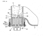
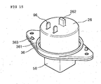
- FIG. 14 is a sectional view of a conductivity sensor and an installation construction thereof according to the sixth embodiment of the present invention
- FIG. 15 is a perspective view of the conductivity sensor shown in FIG. 14 .
- the conductivity sensor according to the sixth embodiment of the present invention includes a pair of electrodes 96, an upper protection member 26, a lower protection member 36 and a sealing member 46, which are identical to those of fifth embodiment described above. A difference is that a temperature sensor 86 is further formed to measure a water temperature.
- the conductivity sensor according to the sixth embodiment of the present invention is characteristic of a coupling structure between the upper protection member 26 and the lower protection member 36 and a coupling structure between the conductivity sensor and the chamber housing 17.
- the temperature sensor 86 is formed in the same manner as the conductivity sensor.
- the temperature sensor 86 is protected by a temperature sensor protection part 286, which is formed as one body together with the upper protection member 26 and sealed. Since the temperature sensor 86 has only to measure a temperature of the washing water, it need not directly contact with the washing water. In addition, the temperature sensor 86 has only to measure a temperature using a calorie transmitter through the temperature sensor protection part 262.
- the conductivity sensor further includes an upper flange 263 extended from the lower end portion of the upper protection member 26, a lower flange 364 arranged with the upper flange 263, and a coupling member 362 passing through the upper and lower flanges 263 and 364 and being inserted up to the chamber housing 17.
- a latch 363 is inserted into a predetermined hole formed at the upper flange 263 in order for a provisional assembly of the upper and lower protection members 26 and 36.
- a fitting guide 361 is protrudedly formed upward on the upper flange 263 and a guide groove 261 is arranged with the fitting guide 361.
- the temperature sensor 86 and the electrodes 96 may be formed in a flat shape, not a circular bar shape.
- a predetermined connector 56 to which a power terminal is connected is further formed downward from the lower protection member 36.
- a liquid sealant for the sealing member 46 is injected to fix a position of the sealing member 46.
- the temperature sensor 86 does not directly contact with the washing water and is sealed with the temperature sensor protection part 262 formed as one body together with the upper protection member 26, such that the temperature sensor 86 is protected.
- the upper flange 263 extended at the lower end portion of the upper protection member 26 and the lower flange 364 extended at the outer periphery of the lower protection member 36 are arranged in a row and coupled with each other.
- the latch 363 protruded upward from the lower flange 364 is inserted into the predetermined hole formed at the upper flange 263 to thereby fix the upper and lower protection members 26 and 36.
- the upper and lower flanges 263 and 364 can be assembled provisionally.
- the provisionally assembled protection members 26 and 36 can be placed at a predetermined position in the lower end portion of the chamber housing 17 in a state that the fitting guide 361 is guided by the guide groove 261.
- the positioned protection members 26 and 36 are firmly fixed and sealed at the opened lower portion of the chamber housing 17 by means of the coupling member 362 passing through the protection members 26 and 36 and the chamber housing 17.
- the water temperature measured by the temperature sensor 86 can be used as a factor that determines an amount of the washing water. For example, in case the temperature of the washing water is high, an activity of the detergent is high such that a small amount of detergent is inputted. Meanwhile, in case the temperature of the washing water is low, an activity of the detergent is low such that a large amount of detergent is inputted in order to obtain the same washing efficiency.
- a seventh embodiment of the present invention will be described in detail with reference to FIGs. 16 and 17 .
- the seventh embodiment of the present invention is mostly identical to the sixth embodiment described above.
- a difference is an additional construction for rapidly discharging foreign substance accumulated inside the pneumatic chamber 11.
- FIG. 16 is a sectional view of a conductivity sensor and an installation construction thereof according to the seventh embodiment of the present invention
- FIG. 17 is a perspective view of the conductivity sensor shown in FIG. 16 .
- an upper surface of the upper protection member 26 is formed convexly to provide a guide part 271 along which foreign substance moves.
- the foreign substance 73 accumulated inside the pneumatic chamber 11 moves toward an edge of the upper protection member 26 along the guide part 271 due to its own weight. While the washing water is being discharged, the foreign substance 73 can be discharged through the inlet/outlet port 16 together with the washing water. At this time, it is preferable that a lower end portion of the inlet/outlet port 16 has a height lower than the edge of the upper protection member 26.
- This embodiment of the present invention has an effect that the conductivity can be measured without any influence of the foreign substance.
- FIGs. 18 to 20 An eighth embodiment of the present invention will be described in detail with reference to FIGs. 18 to 20 .
- the eighth embodiment of the present invention is mostly identical to the seventh embodiment described above.
- a difference is an additional construction for preventing the electrodes and the temperature sensor from being vibrated.
- a vibration continuously occurs in the washing machine due to a driving of the motor and causes the positions of the electrodes and the temperature sensor to be changed. Further, due to the vibration, a contact point may be disconnected. This embodiment is provided for solving these problems.
- FIG. 18 is a sectional view of a conductivity sensor and an installation construction thereof according to the eighth embodiment of the present invention
- FIG. 19 is a perspective view showing a portion of the electrode, which is partially broken away.
- the conductivity sensor according to the eighth embodiment of the present invention includes a pair of electrodes 98, an upper protection member 28, a lower protection member 36, a sealing member 46, a temperature sensor 88, a temperature sensor protection part 262, an upper flange 263, a lower flange 364, a coupling member 362, a latch 363, a fitting guide 361, a guide groove 261, and a connector 56, which are almost identical to those of the seventh embodiment described above.
- the conductivity sensor further includes an electrode support rib 281 extended downward in the inside of the upper protection member 28 and a temperature sensor support rib 282 extended downward in the inside of the upper protection member 28 in the same manner as the electrode support rib 281.
- a sealing member 46 is filled between the electrodes 98 and the temperature sensor 88. Therefore, even though some portion of the sealing member 46 is broken, the sealing member 46 is not damaged entirely.
- the electrodes 98 and the temperature sensor 88 are vibrated, a propagation of the vibration is stopped due to the respective support ribs 281 and 282. As a result, the vibrations of the electrodes 98 and the temperature sensor 88 can be prevented. Further, it is possible to enhance a vibration resistance of the sealing member 46. Specifically, the electrode support rib 281 and the temperature sensor support rib 282 cause the electrodes 98 and the temperature sensor 88 to endure the vibration applied in a right and left direction.
- the conductivity sensor further includes an electrode protrusion 981 formed protrudedly at a predetermined position of the electrode 98 and a temperature sensor protrusion 881 formed protrudedly at a predetermined position of the temperature sensor 88.
- positions of the upper and lower end portions of the electrode protrusion 981 are supported by the electrode support rib 281 and the lower protection rib 36, respectively. Therefore it is possible to prevent the up and down vibration of the electrodes 98, which is caused by the vibration externally applied up and down.
- positions of the upper and lower end portions of the temperature sensor protrusion 881 are supported by the temperature sensor support rib 282 and the lower protection member 36, respectively. Therefore, it is possible to prevent the up and down vibration of the temperature sensor 88, which is caused by the vibration externally applied up and down. In this manner, since the electrodes 98 and the temperature sensor 88 are prevented from being vibrated, the damage of the sealing member 46 can be prevented, thereby improving the performance of the sealing member 46. As a result, the reliability of the sealing can also be improved.
- an electrode fitting groove 283 formed by depressing an end portion of the electrode support rib 281 is provided at a position where the electrodes 98 and the electrode support rib 281 contact with each other
- a temperature sensor fitting groove 284 formed by depressing an end portion of the temperature sensor support rib 282 is provided at a position where the temperature sensor 88 and the temperature sensor support rib 282 contact with each other. Consequently, the electrodes 98 and the temperature sensor 88 can be fitted into accurate positions and supported firmly.
- FIG. 20 is a perspective view showing a lower portion of the electrodes and the temperature sensor fitted into the upper protection member according to the eighth embodiment of the present invention.
- the electrodes 98 and the temperature sensor 88 are fitted into the fitting grooves 283 and 284 formed inside the support ribs 281 and 282.
- an electrode protrusion 981 and a temperature sensor protrusion 881 are internally inserted and fitted into the grooves 283 and 284.
- sealant injection grooves 285 and 286 are formed at another portion where the fitting grooves 283 and 284 are not formed in order for smoothly injecting the liquid sealant among the support ribs 281 and 282, the electrodes 98 and the temperature sensor 88.
- the sealant injection grooves 285 and 286 allow the liquid sealant to be injected smoothly.
- the sealing member 46 formed after the sealant is injected and solidified can support the electrodes 98 and the temperature sensor 88 more firmly.
- the reason why the temperature sensor 88 is branched into two pieces at the lower portion is to secure the reliability of signal transmission and support the sealing member 46 firmly. At this time, the temperature sensor 88 can also be branched into one piece.
- This embodiment can prevent the vibration of the electrodes and the temperature sensor themselves and due to the external impact. Additionally, since the electrodes and the temperature sensor are not vibrated, there is nothing to worry about the disconnection of the respective contact points. Further, the reliability of the product can be improved much more.
- a ninth embodiment of the present invention will be described in detail with reference to FIGs. 21 to 23 .
- This embodiment is characterized in that a specific structure is further formed in order to prevent the electrodes and the temperature sensor from being vibrated.
- FIG. 21 is a sectional view of a conductivity sensor and an installation construction thereof according to the ninth embodiment of the present invention
- FIG. 22 is a perspective view of the conductivity sensor according to the ninth embodiment of the present invention, which is partially broken away.
- this embodiment of the present invention is mostly identical to the eighth embodiment described above.
- a difference is a topology of the electrodes 99 and the temperature sensor 89.
- a predetermined hole is formed at each body of the electrode 99 and the temperature sensor 89.
- each of the electrodes 99 includes: an electrode protrusion 992 formed at a predetermined position of a bar-shaped body to support the position of the electrode; and an electrode fixing hole 991 formed by opening a predetermined position of the body of the electrode 99.
- the temperature sensor 89 includes: a temperature sensor protrusion 892 formed at a predetermined position of a bar-shaped body to support the position of the temperature sensor; and a temperature sensor fixing hole 891 formed by opening a predetermined position of the body of the temperature sensor 89.
- a liquid sealant for the sealing member is injected and solidified in the inside of the electrode fixing hole 991 and the temperature sensor fixing hole 891.
- the liquid sealant is injected up to the insides of the electrode fixing hole 991 and the temperature sensor fixing hole 891 and then solidified. By doing so, the sealant arrives at a wider area and is then solidified, such that the positions of the electrodes 99 and the temperature sensor 89 are supported more reliably by the solidified sealing member 46.
- FIG. 23 is a perspective view of the electrode according to the ninth embodiment of the present invention.
- each of the electrodes 99 consists of a main body formed in a flat shape and a width of the electrode is expanded at a predetermined portion.
- the electrode protrusion 992 for supporting the position of the electrodes 99 is formed.
- the electrode fixing hole 991 in which the sealing member 46 is formed up to the predetermined opened portion is formed in the body of the electrode.
- the temperature sensor 89 can be formed with the same structure as the electrodes 99.
- grooves can be formed instead of the holes because it is essential to seal much wider area in the main body.
- a tenth embodiment of the present invention will be described in detail with reference to FIGs. 24 to 28 .
- the tenth embodiment of the present invention is mostly identical to the eighth embodiment described above.
- a difference is a construction of a connector and a receptacle for transferring an amount of electricity, sensed by the electrodes and the temperature sensor, through a wire.
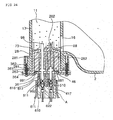
- FIG. 24 is a sectional view of a conductivity sensor and an installation construction thereof according to the tenth embodiment of the present invention
- FIG. 25 is an enlarged view of the portion "A" shown in Fig. 24
- FIG. 26 is a perspective view of a coupling portion between a connector and a receptacle according to the present invention.
- the conductivity sensor includes a pair of electrodes 98, an upper protection member 28, a lower protection member 36, a sealing member 46, a temperature sensor 88, a temperature sensor protection part 262, an upper flange 263, a lower flange 364, a coupling member 362, a latch 363, a fitting guide 361, and a guide groove 261, which are almost identical to those of the eighth embodiment described above.
- the conductivity sensor further includes a connector 510 extended downward from the lower protection member 36 and a receptacle 610 inserted into the connector 510.
- the conductivity sensor includes: a latch protrusion 511 formed protrudedly from an outer periphery of the connector 510; guide holes 992 formed at lower end portions of the electrodes 98 and the temperature sensor 88 in an inside of the connector 510; a receptacle handle 611; a fixing protrusion 612 formed an outer periphery of the receptacle 610 and caught by the latch protrusion 511, in which the fixing protrusion 612 can perform a predetermined elastic restoring motion due to an external force applied by a user; and a position manipulating part 616 inserted in contact with an inner periphery of the connector 510 to allow a clear motion of the receptacle.
- the plate member of a conductive material is deformed to form a conductive member 617 in an inside of the receptacle 610.
- the receptacle includes: a wire fixing part 622 formed at one end portion of the conductive member 617 to hold the wire 623; an inverting part 613 foldedly formed on an opposite side of the wire fixing part 622 provided for an electrical connection at the end portions of the electrodes 98 and the temperature sensor 88; a fitting protrusion 614 fitted in arrangement with the guide hole 992 so that the inserted conductive member cannot be released; and a stopper 615 provided for preventing an excessive insertion of the conductive member 617 after a predetermined length of the conductive member 617 is inserted into the connector 510, in which the conductive member 617 is stopped due to the lower end portions of the electrodes 98 and the temperature sensor 88.
- the fitting protrusion 614 is fitted into the guide hole 992, and the stopper 615 reaches the lower end portions of the electrodes 98 and the temperature sensor 88 and is not inserted any longer.
- the fixing protrusion 612 is caught by the latch protrusion 511, so that it is not released if the user does not apply an external force.
- three coupling structures apply a coupling force at the same time. Therefore, even though an external vibration occurring during an operation of the washing machine is applied, the structures of the connector and the receptacle which respectively act as the input and output terminals of electrical signals are not weakened, so that the connector and the receptacle are not released.
- FIG. 27 is a perspective view of the conductivity sensor according to the tenth embodiment of the present invention
- FIG. 28 is an exploded perspective view of the conductivity sensor shown in FIG. 27 .
- the conductivity sensor includes the upper protection member 28, the lower protection member 36, the connector 510 formed a lower end portion of the lower protection member 36 in a rectangular shape, and the receptacle 610 fitted into the connector 510. Additionally, the conductivity sensor includes the position manipulating part 616 insertedly fitted into the inner periphery of the connector 510 at a fitting end portion of the receptacle 610, and the fixing protrusion 612 and the latch protrusion 511. The end portion of the receptacle 610 is inserted into the connector 510, such that the position of the receptacle 610 is fixed. The position manipulating part 616 is in contact with an inner or outer surface of the opened portions formed inside the connector 510, thereby firmly supporting the position of the receptacle 610.
- This embodiment of the present invention can obtain a stable transmission of electrical signals due to the structures of the connector and the receptacle. Since the washing machine can strongly endure its own vibration due to the above structures of the connector and the receptacle, it is possible to provide a stable sensor structure.
- FIGs. 29 and 30 An eleventh embodiment of the present invention will be described in detail with reference to FIGs. 29 and 30 .
- the eleventh embodiment of the present invention is mostly identical to the tenth embodiment described above. A difference is a structure that allows the receptacle to be simply and stably fitted into the connector.
- FIG. 29 is a perspective view of a conductivity sensor according to the eleventh embodiment of the present invention
- FIG. 30 is an exploded perspective view of the conductivity sensor shown in FIG. 29 .
- the conductivity sensor further includes a connector guide 521 formed on an outer periphery of the connector 520, a receptacle 620 fitted into the connector 520, and a receptacle guide 625 arranged with the connector guide 521 and formed on an outer periphery of the receptacle 620.
- the respective guides 521 and 625 are arranged symmetrically, such that the receptacle 620 is fitted accurately.
- the receptacle guide 625 and the connector guide 521 are formed only on one edge, not four edges. Therefore, if the receptacle guide 625 and the connector guide 521 are not arranged correctly, the receptacle 620 cannot be inserted. As a result, when the user inserts the receptacle 620, there is nothing to worry about an incorrect insertion of the electrodes and the temperature sensor, thereby achieving a stable assembly.
- FIG. 31 is a flowchart illustrating a method for controlling the washing machine according to the present invention.
- the conductivity sensor measures the conductivity of the washing water (ST11). Then, the hardness of the washing water is determined using a predetermined equation or a table, which is prepared previously (ST12).
- the washing water's hardness determined at the step ST12 is used as an information for the entire cycles of the washing machine, which will be performed later. For example, in case the hardness is high, the detergent is not dissolved well. Therefore, the washing cycle is performed with a large amount of detergent and the number of a rinsing operation is decreased. On the contrary, in case the hardness is low, the detergent is dissolved well. Therefore, the washing cycle is performed with a small amount of the detergent and the number of a rinsing operation is increased. Of course, in addition to the hardness of the washing water, the water temperature and the laundry amount can be influenced on the washing cycle.
- a driving method of the washing machine is selected according to the hardness determined at the step ST12 (ST13).
- a washing operation (ST14), a rinsing operation (ST15) and a dewatering operation (ST16) are performed according to the selected driving method. In this manner, the overall washing cycles are completed.
- an optimum washing performance is maintained by properly changing a washing method according to the hardness of the washing water.
- the reliability in the operation of the washing machine is improved by using the measured conductivity of the washing water as various indexes in the operation of the washing machine.
- the conductivity sensor for measuring the conductivity of the washing machine is installed stably, it is possible to prevent the leakage of the washing water and to operate the washing machine stably.
Landscapes
- Engineering & Computer Science (AREA)
- Textile Engineering (AREA)
- Chemical & Material Sciences (AREA)
- Analytical Chemistry (AREA)
- General Health & Medical Sciences (AREA)
- Physics & Mathematics (AREA)
- Health & Medical Sciences (AREA)
- Life Sciences & Earth Sciences (AREA)
- Chemical Kinetics & Catalysis (AREA)
- Biochemistry (AREA)
- Electrochemistry (AREA)
- General Physics & Mathematics (AREA)
- Immunology (AREA)
- Pathology (AREA)
- Control Of Washing Machine And Dryer (AREA)
- Investigating Or Analyzing Materials By The Use Of Electric Means (AREA)
- Measurement Of Resistance Or Impedance (AREA)
Abstract
Description
- The present invention relates to a washing machine capable of measuring a hardness of a washing water. Such a washing machine is known for example from
JP-A-06, 233, 892 - In general, various sensors are installed in a washing machine to sense several washing conditions necessary for a washing operation. The washing machine is appropriately driven according to the sensed washing conditions in order to obtain the maximum washing effect. As sensors of a conventional washing machine, a sensor for sensing an amount of washing water received in a washing tub and a sensor for measuring a water temperature in order to boil the laundry have been proposed and used.
- Meanwhile, one of factors that determine properties of the washing water is a water hardness. The water hardness is a term that represents a degree of a water strength. Materials determining the hardness are calcium, magnesium, iron, strontium, and the like. As well known, in case the water harness is high, a detergent is not dissolved well due to magnesium ions or calcium ions contained in the water, so that a cleaning capacity of the detergent is degraded. Accordingly, the water having a high hardness is not suitable for domestic water or industrial water.
- However, the related art has not proposed a method for adjusting an amount of detergent and water in the washing machine according to the hardness of the washing water. Although different areas have different water hardness, the equal method of inputting detergent and water is applied at every area, which is one of factors that degrade the washing efficiency. Specifically, in an area where underground water is used as the washing water, an equal amount of detergent and water is used while the hardness of the washing water is ignored. This is an important factor that degrades the washing efficiency.
- Accordingly, the present invention is directed to a washing machine that substantially obviates the problems caused by limitations and disadvantage of the conventional one.
- One object of the present invention is to provide a washing machine in which the optimum washing efficiency is obtained by properly changing a washing method according to a hardness of a washing water.
- Another object of the present invention is to provide a washing machine, in which the reliability is improved by using a measured conductivity of a washing water as various indexes of an operation of the washing machine.
- According to one aspect of the present invention, a washing machine includes the combined features of
claim 1. - According to the present invention, the reliability in the operation of the washing machine can be improved. Specifically, the washing efficiency can be improved by adjusting an amount of detergent and washing water according to the hardness of the washing water, which is sensed by the conductivity sensor.
- Further, according to the present invention, the conductivity sensor is stably operated, thereby preventing an erroneous operation of the conductivity sensor, which may be caused by leakage of water and foreign substance.
- The above objects, other features and advantages of the present invention will become more apparent by describing the preferred embodiments thereof with reference to the accompanying drawings, in which:
-
FIG. 1 is a sectional view of a washing machine according to a first embodiment of the present invention; -
FIG. 2 is an enlarged sectional view of the portion "A" shown inFIG. 1 ; -
FIG. 3 is a perspective view of a conductivity sensor according to a first embodiment of the present invention; -
FIG. 4 is a sectional view of a conductivity sensor and an installation construction thereof according to a second embodiment of the present invention; -
FIG. 5 is a perspective view of the conductivity sensor according to the second embodiment of the present invention; -
FIG. 6 is an enlarged view of a receptacle according to a second embodiment of the present invention; -
FIG. 7 is a sectional view of a conductivity sensor and an installation construction thereof according to a third embodiment of the present invention; -
FIG. 8 is a perspective view of the conductivity sensor according to the third embodiment of the present invention; -
FIG. 9 is a perspective view of a conductivity sensor according to a fourth embodiment of the present invention; -
FIG. 10 is a sectional view of the conductivity sensor and an installation construction thereof according to the fourth embodiment of the present invention; -
FIG. 11 is an enlarged sectional view of the portion "A" shown inFIG. 10 ; -
FIG. 12 is a sectional view of a conductivity sensor and an installation construction thereof according to a fifth embodiment of the present invention; -
FIG. 13 is a perspective view of a shield member according to a fifth embodiment of the present invention; -
FIG. 14 is a sectional view of a conductivity sensor and an installation construction thereof according to a sixth embodiment of the present invention; -
FIG. 15 is a perspective view of the conductivity sensor according to the sixth embodiment of the present invention; -
FIG. 16 is a sectional view a conductivity sensor and an installation construction thereof according to a seventh embodiment of the present invention; -
FIG. 17 is a perspective view of the conductivity sensor according to the seventh embodiment of the present invention; -
FIG. 18 is a sectional view of a conductivity sensor and an installation construction thereof according to an eighth embodiment of the present invention; -
FIG. 19 is a perspective view of the conductivity sensor according to the eight embodiment of the present invention, which is partially broken away; -
FIG. 20 is a perspective view showing a lower portion of electrodes and a temperature sensor fitted into an upper protection member according to the eighth embodiment of the present invention; -
FIG. 21 is a sectional view of a conductivity sensor and an installation construction thereof according to a ninth embodiment of the present invention; -
FIG. 22 is a perspective view of the conductive sensor according to the ninth embodiment of the present invention, which is partially broken away; -
FIG. 23 is a perspective view of an electrode according to the ninth embodiment of the present invention; -
FIG. 24 is a sectional view of a conductivity sensor and an installation construction thereof according to a tenth embodiment of the present invention; -
FIG. 25 is an exploded view of the portion "A" shown inFIG. 24 ; -
FIG. 26 is a perspective view showing a coupling portion between a connector and a receptacle according to the tenth embodiment of the present invention; -
FIG. 27 is a perspective view of the conductivity sensor according to the tenth embodiment of the present invention; -
FIG. 28 is an exploded perspective view of the conductivity sensor according to the tenth embodiment of the present invention; -
FIG. 29 is a perspective view of a conductivity sensor according to an eleventh embodiment of the present invention; -
FIG. 30 is an exploded perspective view of the conductivity sensor according to the eleventh embodiment of the present invention; and -
FIG. 31 is a flowchart illustrating a method for controlling a washing machine according to the present invention. - Hereinafter, preferred embodiments of the present invention will be described in detail with reference to the attached drawings. The present invention is not limited to the embodiments and it will be apparent to those skilled in the art that the present invention can be easily applied to other embodiments within the scope of the present invention, indicated by the appended claims.
- A first embodiment of the present invention will be described in detail with reference to
FIGs. 1 to 3 . -
FIG. 1 is a sectional view of a washing machine according to a first embodiment of the present invention. - Referring to
FIG. 1 , the washing machine according to the present invention includes: acabinet 1 forming an outer shell; anouter tub 2 fixedly suspended inside thecabinet 1 by a plurality ofsuspension members 10, for containing a washing water; adamper 14 formed on a lower portion of thesuspension member 10 to attenuate a vibration of theouter tub 2; aninner tub 3 rotatably installed inside theouter tub 2 to receive a laundry and a washing water supplied through a supply valve; apulsator 7 rotatably installed in a lower portion of theinner tub 3 to agitate a water current of the washing water; adrive motor 4 driven by an external power; adrive shaft 5 disposed at a central portion of thedrive motor 4; aclutch 6 installed in a lower portion of theouter tub 2 to selectively rotate theinner tub 3 or thepulsator 7; a manipulation/control unit 8 for controlling a washing cycle and operation of the washing machine; adrain port 15 installed in a lower portion of theouter tub 2 to discharge the washing water from theouter tub 2; adoor 9 mounted on an upper.portion of thecabinet 1 to prevent the laundry from being departed from thecabinet 1 and to prevent an accident; an inlet/outlet port 16 provided at an opened lower portion of theouter tub 2 and through which the washing water is introduced and discharged; apneumatic chamber 11 formed on an outer side of the inlet/outlet port 16; achamber housing 17 having a wall structure for hermetically sealing thepneumatic chamber 11; a water level sensor 12 formed on an upper portion of thepneumatic chamber 11; and aconductivity sensor 13 sealed in a lower portion of thepneumatic chamber 11. - Specifically, a microprocessor and a digital storage media are installed inside the manipulation/
control unit 8 to control an overall operation of the washing machine. - Herein, an operation of the washing machine will be described below.
- A laundry is put in the tub through the
door 9 and the washing machine begins to operate under a control of the manipulation/control unit 8. A power applied through themotor 4, thedrive shaft 5 and the clutch 6 in sequence is supplied to thepulsator 7, such that thepulsator 7 rotates. Thepulsator 7 rotates the washing water and the laundry and causes a friction therebetween. In this manner, a washing operation is performed. After the washing operation is completed, the wastewater is discharged through thedrain port 15. - In addition, an overall cycle of the washing machine is controlled through the manipulation/
control unit 8. A predetermined program stored in the storage media controls themotor 4, a supply/drain value and theclutch 6, such that an overall operation of the washing machine is controlled properly. - Further, the
damper 14 is connected to thecabinet 1 through thesuspension member 10. Thedamper 14 attenuates a vibration of theouter tub 2 to thereby reduce a vibration and movement of the body of the washing machine. - Herein, a sensing means for sensing a quantity and property of the washing water will be described in detail. If the washing water is introduced, the washing water is introduced into the
pneumatic chamber 11 through the inlet/outlet port 16. Theconductivity sensor 13 measures a conductivity of the washing water introduced into thepneumatic chamber 11, and a hardness of the washing water is sensed using the measured conductivity with reference to a predetermined table. The table can be stored in the digital storage media and can be read/controlled by the microprocessor. Here, the digital storage media and the microprocessor are installed inside the manipulation/control unit 8. - In addition, if the washing water continues to be introduced, a water level inside the
pneumatic chamber 11 also rises. At this time, since the inside of thepneumatic chamber 11 is in a hermetically sealed state, the washing water is not discharged. Therefore, as the washing water is introduced into theouter tub 2, the internal pressure of thepneumatic chamber 11 increases. The water level of the washing water introduced inside theouter tub 2 can be measured using a pneumatic of thepneumatic chamber 11. - Specifically, a hydraulic pressure in a lower portion of the
pneumatic chamber 11 is a sum of an air pressure in the inside of thepneumatic chamber 11 and a hydraulic pressure caused due to a water level of thepneumatic chamber 11. The hydraulic pressure in the lower portion of thepneumatic chamber 11 is identical to a total hydraulic pressure in the inside of theouter tub 2. Therefore, the water level of theouter tub 2 can be sensed using the air pressure in the inside of thepneumatic chamber 11. In other words, as the water level of theouter tub 2 rises higher, the air pressure in the inside of thepneumatic chamber 11 increases higher. The water level of theouter tub 2 can be sensed by inversely using a linear relationship of the increasing hydraulic pressure. -
FIG. 2 is an enlarged sectional view of the portion "A" shown inFIG. 1 , andFIG. 3 is a perspective view of a conductivity sensor. - Referring to
FIGs. 2 and3 , theconductivity sensor 13 includes: a pair ofelectrodes 91 formed of a conductive material in a bar shape; anupper protection member 21 for supporting and protecting an upper portion of theelectrodes 91; alower protection member 31 for supporting and protecting a lower portion of theelectrodes 91; a sealingmember 41 filled inside theprotection members upper fixing portion 211 in which theupper protection member 21 and thechamber housing 17 are coupled to each other; alower fixing portion 311 in which theupper protection member 21 and thelower protection member 31 are coupled to each other; and aconnector 51 extended downward from thelower protection member 31. - Specifically, the
conductivity sensor 13 is insertedly installed in an opening of a lower portion of thechamber housing 17 and coupled with thechamber housing 17 at theupper fixing portion 211. Theupper fixing portion 211 can be fixed in any manner, for example, a fusion, an adhesion, a latching structure having a sealing member intervened therein. Of course, thelower fixing portion 311 can also be fixed by a fusion, an adhesion, a latching structure having a sealing member intervened therein. - In more detail, the pair of the
electrodes 91 are formed, and a protruded upper end portion of eachelectrode 91 protruded inside thepneumatic chamber 11 keeps in contact with the washing water. Accordingly, theelectrodes 91 must be made of material, such as stainless or copper, which has a high conductivity and a high corrosion resistance. Among theelectrodes 91, one flows an electric current into the washing water and the other senses an amount of electric current flowing into the washing water. In this manner, the quantity of ions contained in the washing water can be sensed according to the amount of the electric current and the hardness of the washing water can be measured according to the sensed quantity of ions. For example, in case a large quantity of ions exists so that the hardness is high, there is a large amount of electric current and a resistance becomes small. Meanwhile, in case there is a small quantity of ions so that the hardness is low, there is a small amount of electric current and a resistance becomes large. - In addition, the sealing
member 41 can be made of rubber or epoxy material. The sealingmember 41 is interposed among theprotection members electrodes 91 and prevents any leakage of the washing water contained in thepneumatic chamber 11. The sealingmember 41 can be formed by filling an inner space of theupper protection member 21 with a liquid material and then compressing it by a thrust of thelower protection member 31. - A receptacle in which a predetermined terminal is formed is inserted into the
connector 51 to thereby transfer the amount of electric current, sensed by theelectrodes 91, to the manipulation/control unit 8 in a stable state. - In this embodiment, the conductivity of the washing water introduced through the inlet/
outlet port 16 is measured through theelectrodes 91 and the hardness of the washing water is determined according to the measured conductivity. The washing machine can be controlled appropriately by changing the control method of the washing machine according to the determined hardness of the washing water. For example, in case the hardness of the washing water is high, an amount of detergent necessary for washing the laundry is increased. Meanwhile, in case the hardness of the washing water is low, an amount of detergent necessary for washing the laundry is reduced. - In addition, the sealing
member 41, theupper fixing portion 211 and thelower fixing portion 311 can prevent leakage of air or water, which is received in thepneumatic chamber 11. - A second embodiment of the present invention will be described in detail with reference to
FIGs. 4 to 6 . -
FIG. 4 is a sectional view of a conductivity sensor and an installation construction thereof according to the second embodiment of the present invention. - Referring to
FIG. 4 , the conductivity sensor according to the second embodiment of the present invention includes a pair ofelectrodes 91, anupper protection member 21, alower protection member 31, a sealingmember 41, anupper fixing portion 211 and alower fixing portion 311, which are identical to those of the first embodiment described above. A difference is that the conductivity sensor further includes aconnector 52 extended downward from thelower protection member 31, and areceptacle 62 formed in an inside of theconnector 52 and fixed to a lower portion of each electrode in order to apply an electric current, in which the lower portion of each electrode is formed in a circular bar shape. -
FIG. 5 is a perspective view of the conductivity sensor according to the second embodiment of the present invention, andFIG. 6 is an enlarged view of the portion "A" shown inFIG. 5 . - Referring to
FIGs. 5 and 6 , theelectrode 91 has the lower portion formed in a circular bar shape, and thereceptacle 62 includes areceptacle fixing part 621 and awire fixing part 622. Thereceptacle fixing part 621 is rolled around an outer periphery of theelectrode 91, and thewire fixing part 622 is formed at a lower end portion of thereceptacle 62 as one body with thereceptacle fixing part 621. According to the construction described above, the voltage sensed by theelectrodes 91 can be accurately transferred to the manipulation/control unit 8, and the structure for coupling theelectrodes 91 and thereceptacle 62 can be fixed regardless of the vibration of the washing machine. - Meanwhile, the
receptacle fixing part 621 can be provided by rolling a flat-shaped conductor around the outer periphery of theelectrode 91 or can be fixed by forceably inserting theelectrode 91 into thereceptacle fixing part 621. - A third embodiment of the present invention will be descried in detail with reference to
FIGs. 7 and8 . The third embodiment provides a structure that can prevent an erroneous operation of theelectrodes 91, which may be caused by foreign substance introduced inside a pneumatic chamber. The pneumatic chamber is formed in a hollow rod shape elongated upward and downward. Foreign substance, such as fluff or dirt, which is contained in the washing water, may be additionally introduced and stacked in an inside of the pneumatic chamber. If the foreign substance is intervened between the electrodes, the conductivity is changed abnormally, so that an amount of electric current is not sensed accurately. For example, if the foreign substance is intervened between the electrodes, it acts as a kind of conductor or nonconductor, so that an accurate measurement of the conductivity is not achieved. Accordingly, in this embodiment, a means for preventing the intervention of the foreign substance is further provided between the electrodes. -
FIG. 7 is a sectional view of the conductivity sensor and an installation, construction thereof according to the third embodiment of the present invention, andFIG. 8 is a perspective view of the conductivity sensor shown inFIG. 7 . - Referring to
FIGs. 7 and8 , the third embodiment of the present invention is mostly identical to the first and second embodiments described above. The conductivity sensor includes a pair ofelectrodes 91, anupper protection member 21, alower protection member 31, a sealingmember 41, anupper fixing portion 211, and alower fixing portion 311. Further, theupper protection member 21 has an upper surface opened with a predetermined diameter and theelectrodes 91 are protruded through the opening portion of theupper protection member 21. The sealingmember 41 is protruded, through the opening portion of theupper protection member 21 to thereby form anextended sealing part 43. Further, ashield member 431 is interposed at a central portion of the extended sealingpart 43, specifically between theelectrodes 91, to prevent foreign substance from being intervened between theelectrodes 91. - In more detail, the
shield member 431 is elongatedly formed in the central portion between theelectrodes 91 to prevent the electric current from flowing through the lower portion of theelectrodes 91. - Since the electric current flows between the
electrodes 91, inorganic matters contained in the washing water may be precipitated on the upper surface of theupper protection member 21 by an oxidation-reduction reaction. If remnants are accumulated, an error may occur in a value of the electric current. Specifically, since the electric current flows through a shortest path, an error occurs in the measured value of the conductivity in a state thatforeign substance 73 is intervened. - Accordingly, in order to prevent an occurrence of the error in the value of the electric current, which is caused by the precipitation of the
foreign substance 73, theshield member 431 for shielding the lower portion of theelectrodes 91 is previously formed protrudedly on the upper surface of theupper protection member 21 to thereby prevent the electric current from flowing through the lower end portion of theelectrodes 91. Since a value of the conductivity measured through only the exposed portion of theelectrodes 91 is different from that measured in case theentire electrodes 91 are exposed, the measured value is corrected in a process of converting it into a hardness value, thereby making it possible to measure a hardness value identical to a state that is not influenced by the precipitation of theforeign substance 73. - In addition, the
shield member 431 is formed elongatedly at the central portion between theelectrodes 91 in order to prevent the electric current on theelectrodes 91 from flowing laterally. In order to prevent the precipitation of theforeign substance 73, theshield member 431 is formed narrowly in an upper direction. As constructed above, it is possible to prevent an occurrence of an error in the sensed value of the conductivity, which is caused by the foreign substance contained in the washing water: Specifically, it is possible to prevent the intervention of deformed organic/inorganic matters contained in the laundry or the detergent, which is put in the tub during the washing operation. - Meanwhile, the
shield member 431 can be formed on the upper surface of theupper protection member 21. In addition, theforeign substance 73 can be discharged through the inlet/outlet port 16 during a drain cycle of the washing machine. - A fourth embodiment of the present invention will be described in detail with reference to
FIGs. 9 to 11 . The fourth embodiment of the present invention is mostly identical to the third embodiment described above. A difference is a detailed construction of the shield member and a method for forming the same. -
FIG. 9 is a perspective view of a conductivity sensor according to the fourth embodiment of the present invention, andFIG. 10 is a sectional view of the conductivity sensor shown inFIG. 9 and an installation construction thereof. - Referring to
FIGs. 9 and10 , the conductivity sensor according to the fourth embodiment of the present invention includes a pair ofelectrodes 91, anupper protection member 21, alower protection member 31, a sealingmember 41 and anupper fixing portion 211 and alower fixing portion 311, which are identical to those of the first embodiment described above. In addition, the conductivity sensor further includes ashield member 24 formed protrudedly around an outer periphery of theelectrodes 91 on an upper surface of theupper protection member 21. - Specifically, the
shield member 24 is protrudedly formed only on the outer periphery of the-electrodes 91 as one body together with theupper protection member 21. In this manner, like the third embodiment, it is possible to prevent an error of the conductivity, which may be caused by theforeign substance 73. -
FIG. 11 is an enlarged sectional view of the portion "A" shown inFIG. 10 . - Referring to
FIG. 11 , theshield member 24 is formed with a predetermined height T1 in a vertical direction from the upper surface of theupper protection member 21 in order to enclose only a lower portion of theelectrodes 91. protruded in the upper portion of theupper protection member 21. An upper portion of theshield member 24 is inclined at a predetermined slope, such that a diameter becomes smaller in an upper direction. As a result, aninclined surface 241 is formed. - In case foreign substance of the washing water contained in the
pneumatic chamber 11 is precipitated, the foreign substance precipitated on theshield member 24 moves to edges along theinclined surface 241 and is then discharged out of thepneumatic chamber 11. Therefore, no precipitation layer is formed on the upper surface of theshield member 24. - Herein, an operation of the fourth embodiment of the present invention will be described below.
- The
foreign substance 73 is accumulated on the upper surface of theupper protection member 21 in a predetermined thickness T2. However, the protruded portion D of theelectrode 91 is higher than a height T1 of theshield member 24. - The
foreign substance 73 stacked on theupper protection member 21 is swept away together with the washing water during the drain cycle of the washing machine. Therefore, theforeign substance 73 is not stacked above the predetermined thickness T2 and does not influence the operation of theelectrodes 91. - Further, in order to properly discharge the
foreign substance 73, it is preferable that a lower height of the inlet/outlet port 16 is lower than at least an upper height of theupper protection member 21. In this manner, theforeign substance 73 can be eliminated more rapidly. - A fifth embodiment of the present invention will be described in detail with reference to
FIGs. 12 and 13 . The fifth embodiment of the present invention is mostly identical to the fourth embodiment described above. A difference is a construction of the shield member and a method for forming the same. -
FIG. 12 is a sectional view of a conductivity sensor and an installation construction thereof according to the fifth embodiment of the present invention, andFIG. 13 is a perspective view of the shield member shown inFIG. 12 . - Referring to
FIGs. 12 and 13 , a difference between the fifth embodiment and the fourth embodiment is that the shield member is provided with a separate member. Specifically, theshield member 25 is provided with a member separated from theupper protection member 21 and mounted on a lower portion of the exposedelectrode 91. - In more detail, the
shield member 25 is formed in a cylinder shape. Theshield member 25 includes anelectrode inserting hole 251 opened at a central portion and through which one end portion of eachelectrode 91 insertedly passes, and aninclined surface 252 formed extendedly downward from theelectrode inserting hole 251. - In case the
shield member 25 is formed in the above manner, it is possible to obtain the same effect as the fourth embodiment described above. - Meanwhile, in this embodiment, the lower end portion of the inlet/
outlet port 16 is formed equal to or lower than the upper position of theupper protection member 21, such that the foreign substance can be discharged more smoothly during the drain cycle of the washing machine. - A sixth embodiment of the present invention will be described in detail with reference to
FIGs. 14 and15 . The sixth embodiment of the present invention is characteristic of a method for coupling the upper and lower protection members for protecting the electrodes and a method for forming a temperature sensor together with the electrodes. -
FIG. 14 is a sectional view of a conductivity sensor and an installation construction thereof according to the sixth embodiment of the present invention, andFIG. 15 is a perspective view of the conductivity sensor shown inFIG. 14 . - Referring to
FIGs. 14 and15 ,-the conductivity sensor according to the sixth embodiment of the present invention includes a pair ofelectrodes 96, anupper protection member 26, alower protection member 36 and a sealingmember 46, which are identical to those of fifth embodiment described above. A difference is that atemperature sensor 86 is further formed to measure a water temperature. The conductivity sensor according to the sixth embodiment of the present invention is characteristic of a coupling structure between theupper protection member 26 and thelower protection member 36 and a coupling structure between the conductivity sensor and thechamber housing 17. - Specifically, the
temperature sensor 86 is formed in the same manner as the conductivity sensor. Thetemperature sensor 86 is protected by a temperaturesensor protection part 286, which is formed as one body together with theupper protection member 26 and sealed. Since thetemperature sensor 86 has only to measure a temperature of the washing water, it need not directly contact with the washing water. In addition, thetemperature sensor 86 has only to measure a temperature using a calorie transmitter through the temperaturesensor protection part 262. - The conductivity sensor further includes an
upper flange 263 extended from the lower end portion of theupper protection member 26, alower flange 364 arranged with theupper flange 263, and acoupling member 362 passing through the upper andlower flanges chamber housing 17. - Further, a
latch 363 is inserted into a predetermined hole formed at theupper flange 263 in order for a provisional assembly of the upper andlower protection members - In order to correctly fit the provisionally assembled conductivity sensor into the
chamber housing 17, afitting guide 361 is protrudedly formed upward on theupper flange 263 and aguide groove 261 is arranged with thefitting guide 361. - In addition, the
temperature sensor 86 and theelectrodes 96 may be formed in a flat shape, not a circular bar shape. Of course, apredetermined connector 56 to which a power terminal is connected is further formed downward from thelower protection member 36. - Herein, an operation of the sixth embodiment will be described below.
- In a state that the
electrodes 96 and thetemperature sensor 86 are placed, a liquid sealant for the sealingmember 46 is injected to fix a position of the sealingmember 46. At this time, thetemperature sensor 86 does not directly contact with the washing water and is sealed with the temperaturesensor protection part 262 formed as one body together with theupper protection member 26, such that thetemperature sensor 86 is protected. - Then, the
upper flange 263 extended at the lower end portion of theupper protection member 26 and thelower flange 364 extended at the outer periphery of thelower protection member 36 are arranged in a row and coupled with each other. In other words, thelatch 363 protruded upward from thelower flange 364 is inserted into the predetermined hole formed at theupper flange 263 to thereby fix the upper andlower protection members lower flanges protection members chamber housing 17 in a state that thefitting guide 361 is guided by theguide groove 261. The positionedprotection members chamber housing 17 by means of thecoupling member 362 passing through theprotection members chamber housing 17. - Since the process of measuring the conductivity in a state that the conductivity sensor is fixed is identical to that described above, a detailed description will be omitted. The water temperature measured by the
temperature sensor 86 can be used as a factor that determines an amount of the washing water. For example, in case the temperature of the washing water is high, an activity of the detergent is high such that a small amount of detergent is inputted. Meanwhile, in case the temperature of the washing water is low, an activity of the detergent is low such that a large amount of detergent is inputted in order to obtain the same washing efficiency. - A seventh embodiment of the present invention will be described in detail with reference to
FIGs. 16 and17 . The seventh embodiment of the present invention is mostly identical to the sixth embodiment described above. A difference is an additional construction for rapidly discharging foreign substance accumulated inside thepneumatic chamber 11. -
FIG. 16 is a sectional view of a conductivity sensor and an installation construction thereof according to the seventh embodiment of the present invention, andFIG. 17 is a perspective view of the conductivity sensor shown inFIG. 16 . - Referring to
FIGs. 16 and17 , an upper surface of theupper protection member 26 is formed convexly to provide aguide part 271 along which foreign substance moves. Theforeign substance 73 accumulated inside thepneumatic chamber 11 moves toward an edge of theupper protection member 26 along theguide part 271 due to its own weight. While the washing water is being discharged, theforeign substance 73 can be discharged through the inlet/outlet port 16 together with the washing water. At this time, it is preferable that a lower end portion of the inlet/outlet port 16 has a height lower than the edge of theupper protection member 26. - This embodiment of the present invention has an effect that the conductivity can be measured without any influence of the foreign substance.
- An eighth embodiment of the present invention will be described in detail with reference to
FIGs. 18 to 20 . The eighth embodiment of the present invention is mostly identical to the seventh embodiment described above. A difference is an additional construction for preventing the electrodes and the temperature sensor from being vibrated. A vibration continuously occurs in the washing machine due to a driving of the motor and causes the positions of the electrodes and the temperature sensor to be changed. Further, due to the vibration, a contact point may be disconnected. This embodiment is provided for solving these problems. -
FIG. 18 is a sectional view of a conductivity sensor and an installation construction thereof according to the eighth embodiment of the present invention, andFIG. 19 is a perspective view showing a portion of the electrode, which is partially broken away. - Referring to
FIGs. 18 and19 , the conductivity sensor according to the eighth embodiment of the present invention includes a pair ofelectrodes 98, anupper protection member 28, alower protection member 36, a sealingmember 46, atemperature sensor 88, a temperaturesensor protection part 262, anupper flange 263, alower flange 364, acoupling member 362, alatch 363, afitting guide 361, aguide groove 261, and aconnector 56, which are almost identical to those of the seventh embodiment described above. - In this embodiment, the conductivity sensor further includes an
electrode support rib 281 extended downward in the inside of theupper protection member 28 and a temperaturesensor support rib 282 extended downward in the inside of theupper protection member 28 in the same manner as theelectrode support rib 281. In theelectrode support rib 281 and the temperaturesensor support rib 282, a sealingmember 46 is filled between theelectrodes 98 and thetemperature sensor 88. Therefore, even though some portion of the sealingmember 46 is broken, the sealingmember 46 is not damaged entirely. When theelectrodes 98 and thetemperature sensor 88 are vibrated, a propagation of the vibration is stopped due to therespective support ribs electrodes 98 and thetemperature sensor 88 can be prevented. Further, it is possible to enhance a vibration resistance of the sealingmember 46. Specifically, theelectrode support rib 281 and the temperaturesensor support rib 282 cause theelectrodes 98 and thetemperature sensor 88 to endure the vibration applied in a right and left direction. - Additionally, the conductivity sensor further includes an
electrode protrusion 981 formed protrudedly at a predetermined position of theelectrode 98 and atemperature sensor protrusion 881 formed protrudedly at a predetermined position of thetemperature sensor 88. - Further, positions of the upper and lower end portions of the
electrode protrusion 981 are supported by theelectrode support rib 281 and thelower protection rib 36, respectively. Therefore it is possible to prevent the up and down vibration of theelectrodes 98, which is caused by the vibration externally applied up and down. Similarly, positions of the upper and lower end portions of thetemperature sensor protrusion 881 are supported by the temperaturesensor support rib 282 and thelower protection member 36, respectively. Therefore, it is possible to prevent the up and down vibration of thetemperature sensor 88, which is caused by the vibration externally applied up and down. In this manner, since theelectrodes 98 and thetemperature sensor 88 are prevented from being vibrated, the damage of the sealingmember 46 can be prevented, thereby improving the performance of the sealingmember 46. As a result, the reliability of the sealing can also be improved. - Meanwhile, an electrode
fitting groove 283 formed by depressing an end portion of theelectrode support rib 281 is provided at a position where theelectrodes 98 and theelectrode support rib 281 contact with each other, and a temperature sensorfitting groove 284 formed by depressing an end portion of the temperaturesensor support rib 282 is provided at a position where thetemperature sensor 88 and the temperaturesensor support rib 282 contact with each other. Consequently, theelectrodes 98 and thetemperature sensor 88 can be fitted into accurate positions and supported firmly. -
FIG. 20 is a perspective view showing a lower portion of the electrodes and the temperature sensor fitted into the upper protection member according to the eighth embodiment of the present invention. - Referring to
FIG. 20 , theelectrode support rib 281 and the temperaturesensor support rib 282, which are extended from the lower portion of theupper protection member 28, are protrudedly formed in a rectangular shape. Theelectrodes 98 and thetemperature sensor 88 are fitted into thefitting grooves support ribs electrode protrusion 981 and atemperature sensor protrusion 881 are internally inserted and fitted into thegrooves - Meanwhile, in the
electrode support rib 281 and the temperaturesensor support rib 282,sealant injection grooves fitting grooves support ribs electrodes 98 and thetemperature sensor 88. Thesealant injection grooves member 46 formed after the sealant is injected and solidified can support theelectrodes 98 and thetemperature sensor 88 more firmly. - The reason why the
temperature sensor 88 is branched into two pieces at the lower portion is to secure the reliability of signal transmission and support the sealingmember 46 firmly. At this time, thetemperature sensor 88 can also be branched into one piece. - This embodiment can prevent the vibration of the electrodes and the temperature sensor themselves and due to the external impact. Additionally, since the electrodes and the temperature sensor are not vibrated, there is nothing to worry about the disconnection of the respective contact points. Further, the reliability of the product can be improved much more.
- A ninth embodiment of the present invention will be described in detail with reference to
FIGs. 21 to 23 . This embodiment is characterized in that a specific structure is further formed in order to prevent the electrodes and the temperature sensor from being vibrated. -
FIG. 21 is a sectional view of a conductivity sensor and an installation construction thereof according to the ninth embodiment of the present invention, andFIG. 22 is a perspective view of the conductivity sensor according to the ninth embodiment of the present invention, which is partially broken away. - Referring to
FIGs. 21 and22 , this embodiment of the present invention is mostly identical to the eighth embodiment described above. A difference is a topology of theelectrodes 99 and thetemperature sensor 89. In other words, a predetermined hole is formed at each body of theelectrode 99 and thetemperature sensor 89. - Specifically, each of the
electrodes 99 includes: anelectrode protrusion 992 formed at a predetermined position of a bar-shaped body to support the position of the electrode; and anelectrode fixing hole 991 formed by opening a predetermined position of the body of theelectrode 99. Like theelectrodes 99, thetemperature sensor 89 includes: atemperature sensor protrusion 892 formed at a predetermined position of a bar-shaped body to support the position of the temperature sensor; and a temperaturesensor fixing hole 891 formed by opening a predetermined position of the body of thetemperature sensor 89. - The construction and operation of the
electrode protrusion 992 and thetemperature sensor protrusion 892 are identical to those of the eighth embodiment described above. Herein, the operations of theelectrode fixing hole 991 and the temperaturesensor fixing hole 891 will be described below. A liquid sealant for the sealing member is injected and solidified in the inside of theelectrode fixing hole 991 and the temperaturesensor fixing hole 891. The liquid sealant is injected up to the insides of theelectrode fixing hole 991 and the temperaturesensor fixing hole 891 and then solidified. By doing so, the sealant arrives at a wider area and is then solidified, such that the positions of theelectrodes 99 and thetemperature sensor 89 are supported more reliably by the solidified sealingmember 46. -
FIG. 23 is a perspective view of the electrode according to the ninth embodiment of the present invention. - Referring to
FIG. 23 , each of theelectrodes 99 consists of a main body formed in a flat shape and a width of the electrode is expanded at a predetermined portion. In this manner, theelectrode protrusion 992 for supporting the position of theelectrodes 99 is formed. Additionally, theelectrode fixing hole 991 in which the sealingmember 46 is formed up to the predetermined opened portion is formed in the body of the electrode. Of course, thetemperature sensor 89 can be formed with the same structure as theelectrodes 99. Although the formations of theelectrode fixing hole 991 and the temperaturesensor fixing hole 891 are described in this embodiment, grooves can be formed instead of the holes because it is essential to seal much wider area in the main body. - A tenth embodiment of the present invention will be described in detail with reference to
FIGs. 24 to 28 . The tenth embodiment of the present invention is mostly identical to the eighth embodiment described above. A difference is a construction of a connector and a receptacle for transferring an amount of electricity, sensed by the electrodes and the temperature sensor, through a wire. -
FIG. 24 is a sectional view of a conductivity sensor and an installation construction thereof according to the tenth embodiment of the present invention,FIG. 25 is an enlarged view of the portion "A" shown inFig. 24 , andFIG. 26 is a perspective view of a coupling portion between a connector and a receptacle according to the present invention. - Referring to
FIGs. 24 and25 , the conductivity sensor according to the tenth embodiment of the present invention includes a pair ofelectrodes 98, anupper protection member 28, alower protection member 36, a sealingmember 46, atemperature sensor 88, a temperaturesensor protection part 262, anupper flange 263, alower flange 364, acoupling member 362, alatch 363, afitting guide 361, and aguide groove 261, which are almost identical to those of the eighth embodiment described above. A difference is that the conductivity sensor further includes aconnector 510 extended downward from thelower protection member 36 and areceptacle 610 inserted into theconnector 510. - In other words, the conductivity sensor includes: a
latch protrusion 511 formed protrudedly from an outer periphery of theconnector 510; guideholes 992 formed at lower end portions of theelectrodes 98 and thetemperature sensor 88 in an inside of theconnector 510; areceptacle handle 611; a fixingprotrusion 612 formed an outer periphery of thereceptacle 610 and caught by thelatch protrusion 511, in which the fixingprotrusion 612 can perform a predetermined elastic restoring motion due to an external force applied by a user; and aposition manipulating part 616 inserted in contact with an inner periphery of theconnector 510 to allow a clear motion of the receptacle. - Herein, the operation of the
connector 510 and thereceptacle 610 will be described below with reference toFIG. 26 . The plate member of a conductive material is deformed to form aconductive member 617 in an inside of thereceptacle 610. The receptacle includes: awire fixing part 622 formed at one end portion of theconductive member 617 to hold thewire 623; an invertingpart 613 foldedly formed on an opposite side of thewire fixing part 622 provided for an electrical connection at the end portions of theelectrodes 98 and thetemperature sensor 88; afitting protrusion 614 fitted in arrangement with theguide hole 992 so that the inserted conductive member cannot be released; and astopper 615 provided for preventing an excessive insertion of theconductive member 617 after a predetermined length of theconductive member 617 is inserted into theconnector 510, in which theconductive member 617 is stopped due to the lower end portions of theelectrodes 98 and thetemperature sensor 88. - Accordingly, if the
receptacle 610 and theconductive member 617 are inserted as much as a predetermined depth, thefitting protrusion 614 is fitted into theguide hole 992, and thestopper 615 reaches the lower end portions of theelectrodes 98 and thetemperature sensor 88 and is not inserted any longer. Additionally, the fixingprotrusion 612 is caught by thelatch protrusion 511, so that it is not released if the user does not apply an external force. As a result, three coupling structures apply a coupling force at the same time. Therefore, even though an external vibration occurring during an operation of the washing machine is applied, the structures of the connector and the receptacle which respectively act as the input and output terminals of electrical signals are not weakened, so that the connector and the receptacle are not released. -
FIG. 27 is a perspective view of the conductivity sensor according to the tenth embodiment of the present invention, andFIG. 28 is an exploded perspective view of the conductivity sensor shown inFIG. 27 . - Referring to
FIGs. 27 and28 , the conductivity sensor includes theupper protection member 28, thelower protection member 36, theconnector 510 formed a lower end portion of thelower protection member 36 in a rectangular shape, and thereceptacle 610 fitted into theconnector 510. Additionally, the conductivity sensor includes theposition manipulating part 616 insertedly fitted into the inner periphery of theconnector 510 at a fitting end portion of thereceptacle 610, and the fixingprotrusion 612 and thelatch protrusion 511. The end portion of thereceptacle 610 is inserted into theconnector 510, such that the position of thereceptacle 610 is fixed. Theposition manipulating part 616 is in contact with an inner or outer surface of the opened portions formed inside theconnector 510, thereby firmly supporting the position of thereceptacle 610. - This embodiment of the present invention can obtain a stable transmission of electrical signals due to the structures of the connector and the receptacle. Since the washing machine can strongly endure its own vibration due to the above structures of the connector and the receptacle, it is possible to provide a stable sensor structure.
- An eleventh embodiment of the present invention will be described in detail with reference to
FIGs. 29 and30 . The eleventh embodiment of the present invention is mostly identical to the tenth embodiment described above. A difference is a structure that allows the receptacle to be simply and stably fitted into the connector. -
FIG. 29 is a perspective view of a conductivity sensor according to the eleventh embodiment of the present invention, andFIG. 30 is an exploded perspective view of the conductivity sensor shown inFIG. 29 . - Referring to
FIGs. 29 and30 , most portions are identical to the tenth embodiment described above. The conductivity sensor further includes aconnector guide 521 formed on an outer periphery of theconnector 520, areceptacle 620 fitted into theconnector 520, and areceptacle guide 625 arranged with theconnector guide 521 and formed on an outer periphery of thereceptacle 620. - When the
receptacle 620 is fitted into theconnector 520, therespective guides receptacle 620 is fitted accurately. Specifically, thereceptacle guide 625 and theconnector guide 521 are formed only on one edge, not four edges. Therefore, if thereceptacle guide 625 and theconnector guide 521 are not arranged correctly, thereceptacle 620 cannot be inserted. As a result, when the user inserts thereceptacle 620, there is nothing to worry about an incorrect insertion of the electrodes and the temperature sensor, thereby achieving a stable assembly. - Further, due to the forcible insertion of the
guides receptacle 620 is increased much more. - Hereinafter, a controlling method for operating the washing machine according to the above-described various embodiments will be described.
-
FIG. 31 is a flowchart illustrating a method for controlling the washing machine according to the present invention. - Referring to
FIG. 31 , if the laundry and the washing water are put in the drum, the conductivity sensor measures the conductivity of the washing water (ST11). Then, the hardness of the washing water is determined using a predetermined equation or a table, which is prepared previously (ST12). The washing water's hardness determined at the step ST12 is used as an information for the entire cycles of the washing machine, which will be performed later. For example, in case the hardness is high, the detergent is not dissolved well. Therefore, the washing cycle is performed with a large amount of detergent and the number of a rinsing operation is decreased. On the contrary, in case the hardness is low, the detergent is dissolved well. Therefore, the washing cycle is performed with a small amount of the detergent and the number of a rinsing operation is increased. Of course, in addition to the hardness of the washing water, the water temperature and the laundry amount can be influenced on the washing cycle. - A driving method of the washing machine is selected according to the hardness determined at the step ST12 (ST13). A washing operation (ST14), a rinsing operation (ST15) and a dewatering operation (ST16) are performed according to the selected driving method. In this manner, the overall washing cycles are completed.
- According to the present invention, an optimum washing performance is maintained by properly changing a washing method according to the hardness of the washing water.
- Additionally, the reliability in the operation of the washing machine is improved by using the measured conductivity of the washing water as various indexes in the operation of the washing machine.
- Further, since the conductivity sensor for measuring the conductivity of the washing machine is installed stably, it is possible to prevent the leakage of the washing water and to operate the washing machine stably.
Claims (26)
- A washing machine comprising:a pair of electrodes (91) formed inside an outer tub (2) containing a washing water when in use, the pair of electrodes being adapted to contact the washing water to measure a conductivity of the washing water;a protection member for protecting the electrodes, the electrodes passing through the protection member;a housing (17) in which one side of the protection member is sealed;a sealing member (41) formed in at least a contact surface between the protection member and the electrodes; anda controller (8) for controlling the washing machine according to the measured conductivity of the washing water,characterised in that the protection member includes:an upper protection part (21) for supporting an upper portion of the electrodes; anda lower protection part (31) for supporting a lower portion of the electrodes.
- The washing machine according to claim 1, wherein the electrodes are formed inside a pneumatic chamber, the pneumatic chamber communicating with the outer tub through an inlet/outlet port formed at a lower portion of the outer tub.
- The washing machine according to claim 1, wherein the electrodes are sealed in a lower portion of the pneumatic chamber sensing a water level.
- The washing machine according to claim 1, wherein the protection member and the housing are fused with each other.
- The washing machine according to claim 1, wherein the housing is a chamber housing forming a pneumatic chamber.
- The washing machine according to claim 1, wherein the sealing member is made of rubber resin or epoxy resin.
- The washing machine according to claim 1, wherein the sealing member is formed by injecting and solidifying a liquid resin.
- The washing machine according to claim 1, wherein an upper surface of the upper protection member is formed convexly.
- The washing machine according to claim 1, further comprising a receptacle connected to a lower end portion of the electrodes.
- The washing machine according to claim 1, further comprising a shield member for preventing an erroneous operation due to foreign substance between the electrodes.
- The washing machine according to claim 1, further comprising a shield member formed between the electrodes by convexly forming the sealing member.
- The washing machine according to claim 1, further comprising a shield member formed between the electrodes to prevent an erroneous operation due to foreign substance, a thickness of the shield member being reduced in an upward direction.
- The washing machine according to claim 1, further comprising a circular shield member formed on each outer periphery of the electrodes, an upper portion of the shield member being inclined narrowly.
- The washing machine according to claims 10-13, wherein the shield member and the protection member are formed as one body.
- The washing machine according to claims 10-13, wherein the shield member is separately inserted into an outer periphery of the electrodes.
- The washing machine according to claim 1, further comprising an inlet/outlet port formed at the outer tub, a lower end portion of the inlet/outlet port being lower than an upper end portion of the protection member.
- The washing machine according to claim 1, wherein the upper and lower protection parts are provisionally assembled with each other by means of a latch structure.
- The washing machine according to claim 1, wherein the protection member and the housing are threadedly connected to each other.
- The washing machine according to claim 1, further comprising a guide structure formed on one side surface of the protection member and a surface corresponding to the housing.
- The washing machine according to claim 1, wherein the electrodes are formed in a flat shape.
- The washing machine according to claim 1, further comprising an electrode support rib extended to an inner side of the protection member and formed at a spaced-apart outer side of the electrodes.
- The washing machine according to claim 1, further comprising an electrode protrusion formed protrudedly on an outer periphery of the electrodes to support positions of the electrodes.
- The washing machine according to claim 1, further comprising an electrode protrusion for supporting the electrodes, the electrode protrusion being formed protrudedly from an outer periphery of the electrodes and contacting with the protection member and/or the extended portion of the protection member.
- The washing machine according to claim 22, further comprising a fitting groove into which the electrode protrusion is fitted, the fitting groove being formed at the extended portion of the protection member.
- The washing machine according to claim 1, further comprising an electrode support rib having a predetermined injection groove through which the sealing member is introduced between the electrodes.
- The washing machine according to claim 1, wherein a deformation portion in which the sealing member is introduced is formed on the electrodes.
Applications Claiming Priority (17)
| Application Number | Priority Date | Filing Date | Title |
|---|---|---|---|
| KR2002075008 | 2002-11-28 | ||
| KR10-2002-0075008A KR100457578B1 (en) | 2002-11-28 | 2002-11-28 | conductivity sensor of washer |
| KR2002075356 | 2002-11-29 | ||
| KR10-2002-0075356A KR100484842B1 (en) | 2002-11-29 | 2002-11-29 | A washing machine being possible to sense the hardness of water and washing method for the same |
| KR1020030005592A KR100712901B1 (en) | 2003-01-28 | 2003-01-28 | Water hardness sensor for washing machine |
| KR2003005592 | 2003-01-28 | ||
| KR2003020211 | 2003-03-31 | ||
| KR1020030020211A KR100680195B1 (en) | 2003-03-31 | 2003-03-31 | A water quality sensor of washing machine |
| KR1020030020834A KR20040085968A (en) | 2003-04-02 | 2003-04-02 | Water quality sensor |
| KR1020030020832A KR20040085966A (en) | 2003-04-02 | 2003-04-02 | Water quality sensor for washing machine |
| KR2003020832 | 2003-04-02 | ||
| KR1020030020833A KR100680196B1 (en) | 2003-04-02 | 2003-04-02 | Water quality sensor for washing machine |
| KR2003020833 | 2003-04-02 | ||
| KR2003020834 | 2003-04-02 | ||
| KR2003021446 | 2003-04-04 | ||
| KR1020030021446A KR20040087177A (en) | 2003-04-04 | 2003-04-04 | Electrode structure of water quality sensor |
| PCT/KR2003/002583 WO2004048676A1 (en) | 2002-11-28 | 2003-11-27 | Washing machine, conductivity sensor in washing machine, and controlling method of the same |
Publications (3)
| Publication Number | Publication Date |
|---|---|
| EP1565608A1 EP1565608A1 (en) | 2005-08-24 |
| EP1565608A4 EP1565608A4 (en) | 2007-02-21 |
| EP1565608B1 true EP1565608B1 (en) | 2011-10-05 |
Family
ID=36113892
Family Applications (1)
| Application Number | Title | Priority Date | Filing Date |
|---|---|---|---|
| EP03774339A Expired - Lifetime EP1565608B1 (en) | 2002-11-28 | 2003-11-27 | Washing machine, conductivity sensor in washing machine, and controlling method of the same |
Country Status (6)
| Country | Link |
|---|---|
| EP (1) | EP1565608B1 (en) |
| JP (2) | JP2006507915A (en) |
| CN (1) | CN100532689C (en) |
| AT (1) | ATE527404T1 (en) |
| AU (1) | AU2003284774B2 (en) |
| WO (1) | WO2004048676A1 (en) |
Families Citing this family (23)
| Publication number | Priority date | Publication date | Assignee | Title |
|---|---|---|---|---|
| JP2005124768A (en) * | 2003-10-23 | 2005-05-19 | Matsushita Electric Ind Co Ltd | Detection electrode device |
| DE102005007935A1 (en) * | 2005-02-15 | 2006-08-24 | E.G.O. Elektro-Gerätebau GmbH | Heating device for an electrical appliance |
| US7709265B2 (en) | 2005-03-24 | 2010-05-04 | Johnsondiversey, Inc. | Method and system for measuring water hardness |
| US20100251780A1 (en) * | 2007-11-20 | 2010-10-07 | Lg Electronics Inc. | Laundry Treatment Machine And A Sensor For Sensing the Quality of Water Therefor |
| CN101736552B (en) * | 2008-11-17 | 2013-02-20 | 海尔集团公司 | Method for detecting washing powder residue and washing machine |
| JP4909388B2 (en) * | 2009-08-25 | 2012-04-04 | パナソニック株式会社 | Washing machine |
| JP4909389B2 (en) * | 2009-08-25 | 2012-04-04 | パナソニック株式会社 | Washing machine |
| JP5485018B2 (en) * | 2010-05-24 | 2014-05-07 | 日立アプライアンス株式会社 | Washing machine |
| KR20120089098A (en) * | 2011-02-01 | 2012-08-09 | 삼성전자주식회사 | Tub and washing machine having the same |
| ITTO20110258A1 (en) * | 2011-03-24 | 2012-09-25 | Eltek Spa | SENSOR AND / OR DUCT FOR DETECTION OF LIQUIDS, IN PARTICULAR FUELS FOR VEHICLES |
| JP5588916B2 (en) * | 2011-04-19 | 2014-09-10 | 日立アプライアンス株式会社 | Washing machine |
| JP5707246B2 (en) * | 2011-06-22 | 2015-04-22 | 日立アプライアンス株式会社 | Washing machine |
| CN102535112B (en) * | 2012-02-16 | 2016-12-14 | 海尔集团公司 | The circuit of detection detergent and method |
| CN102623835B (en) * | 2012-03-14 | 2014-12-10 | 中航光电科技股份有限公司 | Reliably working waterproof connector |
| CN102634958A (en) * | 2012-03-28 | 2012-08-15 | 海尔集团公司 | Washing machine as well as control method and control device thereof |
| CN105002697B (en) * | 2015-06-26 | 2017-08-25 | 万乐予 | The washing machine of electrode with measurement water conductivity |
| CN105040364B (en) * | 2015-06-26 | 2018-09-25 | 陈凤花 | The washing machine of the water hardness can be measured |
| CN105040365A (en) * | 2015-06-26 | 2015-11-11 | 叶金仁 | Washing machine with telescopic electrode |
| ES1148118Y (en) * | 2015-10-21 | 2016-03-15 | Dinfer Electronica S L | CONDUCTIVITY PROBE |
| FR3045680B1 (en) * | 2015-12-18 | 2019-07-19 | Groupe Brandt | METHOD OF OPERATING A WASHING APPARATUS ACCORDING TO A SET OF OPERATING PARAMETERS |
| DE102019123761A1 (en) * | 2019-09-05 | 2021-03-11 | Stiebel Eltron Gmbh & Co. Kg | Hold-down device for holding down a measuring sensor and forwarding an electrical measuring signal |
| JP7390650B2 (en) * | 2019-12-26 | 2023-12-04 | 青島海爾洗衣机有限公司 | washing machine |
| CN111615279A (en) * | 2020-04-17 | 2020-09-01 | 中国电子科技集团公司第五十三研究所 | Split type photoelectric equipment protection device |
Family Cites Families (23)
| Publication number | Priority date | Publication date | Assignee | Title |
|---|---|---|---|---|
| US3223108A (en) * | 1962-08-21 | 1965-12-14 | Whirlpool Co | Control for laundry apparatus |
| US3645669A (en) * | 1969-02-28 | 1972-02-29 | Gerhard Rausch | Method and arrangement for testing the liquid in washing machines |
| AU523922B2 (en) * | 1978-04-28 | 1982-08-19 | Tokyo Shibaura Electric Company Ltd. | Apparatus for measuring the degree of rinsing |
| JPS5568384A (en) * | 1978-11-17 | 1980-05-23 | Hitachi Ltd | Operating device of washing machine |
| DE8234663U1 (en) * | 1982-12-10 | 1983-06-23 | Standard Elektrik Lorenz Ag, 7000 Stuttgart | FOR RECEIVING A METAL CONTAINER OF LIQUID |
| DE3305784A1 (en) * | 1983-02-19 | 1984-08-23 | Lang Apparatebau GmbH, 8227 Siegsdorf | ELECTRICAL CONDUCTIVITY SENSOR |
| JPH0415185Y2 (en) * | 1985-06-07 | 1992-04-06 | ||
| JPH04288196A (en) * | 1991-03-18 | 1992-10-13 | Hitachi Ltd | Washing control for washing machine |
| JPH04288194A (en) * | 1991-03-18 | 1992-10-13 | Hitachi Ltd | Washing control for waching machine |
| KR920018284A (en) * | 1991-03-29 | 1992-10-21 | 가나이 쓰도무 | washer |
| JP2944789B2 (en) * | 1991-07-12 | 1999-09-06 | 株式会社東芝 | Washing machine |
| JPH06218183A (en) * | 1993-01-22 | 1994-08-09 | Toshiba Corp | Washing machine |
| JPH06233892A (en) * | 1993-02-10 | 1994-08-23 | Toshiba Corp | Washing machine |
| DE69323073T2 (en) * | 1993-07-06 | 1999-08-05 | Whirlpool Europe B.V., Veldhoven | Method and device for automatically optimizing the amount of detergent in a washing machine, washer dryer, dishwasher or the like by measuring the water hardness |
| JP3066228B2 (en) * | 1993-07-28 | 2000-07-17 | シャープ株式会社 | Washing machine washing control device |
| DE19541719A1 (en) * | 1995-11-09 | 1997-05-15 | Foron Hausgeraete Gmbh | Determining harness of water used as solvent |
| JPH10153481A (en) * | 1996-11-22 | 1998-06-09 | Shimada Denshi Kogyo Kk | Highly sensitive submergible optical sensor and its manufacture |
| DE19858386B4 (en) * | 1998-12-17 | 2008-04-03 | BSH Bosch und Siemens Hausgeräte GmbH | Transmissionsmeßvorrichtung |
| JP2001017775A (en) * | 1999-07-06 | 2001-01-23 | Toshiba Corp | Washing machine |
| JP2001293284A (en) * | 2000-04-13 | 2001-10-23 | Hitachi Ltd | Washing machine |
| JP2002050428A (en) * | 2000-05-26 | 2002-02-15 | Yukita Electric Wire Co Ltd | Attachment plug |
| JP2002305065A (en) * | 2001-04-04 | 2002-10-18 | Nippon Mektron Ltd | Sealing method between connector terminal insertion opening and electric wire, and waterproofing connector |
| JP2003163051A (en) * | 2001-11-28 | 2003-06-06 | Kazuhiro Imai | Plug receptacle preventing tracking and power supply plug |
-
2003
- 2003-11-27 EP EP03774339A patent/EP1565608B1/en not_active Expired - Lifetime
- 2003-11-27 CN CNB200380100062XA patent/CN100532689C/en not_active Expired - Fee Related
- 2003-11-27 AU AU2003284774A patent/AU2003284774B2/en not_active Ceased
- 2003-11-27 AT AT03774339T patent/ATE527404T1/en not_active IP Right Cessation
- 2003-11-27 JP JP2005510301A patent/JP2006507915A/en active Pending
- 2003-11-27 WO PCT/KR2003/002583 patent/WO2004048676A1/en active IP Right Grant
-
2009
- 2009-05-15 JP JP2009118786A patent/JP4750199B2/en not_active Expired - Fee Related
Also Published As
| Publication number | Publication date |
|---|---|
| CN100532689C (en) | 2009-08-26 |
| WO2004048676A1 (en) | 2004-06-10 |
| AU2003284774B8 (en) | 2004-06-18 |
| ATE527404T1 (en) | 2011-10-15 |
| EP1565608A4 (en) | 2007-02-21 |
| JP2006507915A (en) | 2006-03-09 |
| AU2003284774B2 (en) | 2007-06-21 |
| JP4750199B2 (en) | 2011-08-17 |
| JP2009195737A (en) | 2009-09-03 |
| CN1685103A (en) | 2005-10-19 |
| AU2003284774A1 (en) | 2004-06-18 |
| EP1565608A1 (en) | 2005-08-24 |
Similar Documents
| Publication | Publication Date | Title |
|---|---|---|
| EP1565608B1 (en) | Washing machine, conductivity sensor in washing machine, and controlling method of the same | |
| US8424345B2 (en) | Washing machine, conductivity sensor in washing machine, and controlling method of the same | |
| EP1859093B1 (en) | Steam generator for washing or drying machine having a water level sensor | |
| EP2527515B1 (en) | Water level sensing apparatus, water supply hose and washing machine having the same | |
| CN101481863B (en) | Washing machine, conductivity sensor in washing machine, and controlling method of the same | |
| EP2227580A2 (en) | Laundry treatment machine and a sensor for sensing the quality of water therefor | |
| KR102653625B1 (en) | Hydraulic regulating devices for domestic liquid-transfer devices or systems | |
| US20020131475A1 (en) | Temperature sensor | |
| KR100452385B1 (en) | A water hardness sensing apparatus for washing machine | |
| KR100748977B1 (en) | Drum washing machine | |
| CN111676647A (en) | Washing machine | |
| CN100519884C (en) | Unit of washing machine for detecting temperature of water | |
| CN215906420U (en) | Put in box subassembly and have its washing machine | |
| KR100484842B1 (en) | A washing machine being possible to sense the hardness of water and washing method for the same | |
| CN213640760U (en) | Intelligent floor washing machine and water tank no-load detection device | |
| CN116770553A (en) | Water level detection device for pulsator washing machine and pulsator washing machine | |
| KR20070059413A (en) | Water quality sensing structure of washing machine | |
| KR20050021061A (en) | waterproof structure of detecting apparatus in the washing machine | |
| KR20040047230A (en) | A water hardness sensing apparatus of water for washing machine | |
| KR100825954B1 (en) | washing machine | |
| KR20040085968A (en) | Water quality sensor | |
| KR20040047198A (en) | A washing machine with apparatus for sensing the quality of water and washing method for the same | |
| KR20040046962A (en) | an electrode sensor of washer | |
| KR20040087177A (en) | Electrode structure of water quality sensor | |
| KR20050110852A (en) | An electrode sensor of a washer |
Legal Events
| Date | Code | Title | Description |
|---|---|---|---|
| PUAI | Public reference made under article 153(3) epc to a published international application that has entered the european phase |
Free format text: ORIGINAL CODE: 0009012 |
|
| 17P | Request for examination filed |
Effective date: 20040721 |
|
| AK | Designated contracting states |
Kind code of ref document: A1 Designated state(s): AT BE BG CH CY CZ DE DK EE ES FI FR GB GR HU IE IT LI LU MC NL PT RO SE SI SK TR |
|
| AX | Request for extension of the european patent |
Extension state: AL LT LV MK |
|
| DAX | Request for extension of the european patent (deleted) | ||
| A4 | Supplementary search report drawn up and despatched |
Effective date: 20070124 |
|
| 17Q | First examination report despatched |
Effective date: 20101216 |
|
| GRAP | Despatch of communication of intention to grant a patent |
Free format text: ORIGINAL CODE: EPIDOSNIGR1 |
|
| GRAS | Grant fee paid |
Free format text: ORIGINAL CODE: EPIDOSNIGR3 |
|
| GRAA | (expected) grant |
Free format text: ORIGINAL CODE: 0009210 |
|
| AK | Designated contracting states |
Kind code of ref document: B1 Designated state(s): AT BE BG CH CY CZ DE DK EE ES FI FR GB GR HU IE IT LI LU MC NL PT RO SE SI SK TR |
|
| REG | Reference to a national code |
Ref country code: GB Ref legal event code: FG4D |
|
| REG | Reference to a national code |
Ref country code: CH Ref legal event code: EP |
|
| REG | Reference to a national code |
Ref country code: IE Ref legal event code: FG4D |
|
| REG | Reference to a national code |
Ref country code: DE Ref legal event code: R096 Ref document number: 60338656 Country of ref document: DE Effective date: 20111201 |
|
| REG | Reference to a national code |
Ref country code: NL Ref legal event code: VDEP Effective date: 20111005 |
|
| PG25 | Lapsed in a contracting state [announced via postgrant information from national office to epo] |
Ref country code: SI Free format text: LAPSE BECAUSE OF FAILURE TO SUBMIT A TRANSLATION OF THE DESCRIPTION OR TO PAY THE FEE WITHIN THE PRESCRIBED TIME-LIMIT Effective date: 20111005 |
|
| REG | Reference to a national code |
Ref country code: AT Ref legal event code: MK05 Ref document number: 527404 Country of ref document: AT Kind code of ref document: T Effective date: 20111005 |
|
| PG25 | Lapsed in a contracting state [announced via postgrant information from national office to epo] |
Ref country code: BE Free format text: LAPSE BECAUSE OF FAILURE TO SUBMIT A TRANSLATION OF THE DESCRIPTION OR TO PAY THE FEE WITHIN THE PRESCRIBED TIME-LIMIT Effective date: 20111005 |
|
| PG25 | Lapsed in a contracting state [announced via postgrant information from national office to epo] |
Ref country code: GR Free format text: LAPSE BECAUSE OF FAILURE TO SUBMIT A TRANSLATION OF THE DESCRIPTION OR TO PAY THE FEE WITHIN THE PRESCRIBED TIME-LIMIT Effective date: 20120106 Ref country code: PT Free format text: LAPSE BECAUSE OF FAILURE TO SUBMIT A TRANSLATION OF THE DESCRIPTION OR TO PAY THE FEE WITHIN THE PRESCRIBED TIME-LIMIT Effective date: 20120206 Ref country code: SE Free format text: LAPSE BECAUSE OF FAILURE TO SUBMIT A TRANSLATION OF THE DESCRIPTION OR TO PAY THE FEE WITHIN THE PRESCRIBED TIME-LIMIT Effective date: 20111005 Ref country code: NL Free format text: LAPSE BECAUSE OF FAILURE TO SUBMIT A TRANSLATION OF THE DESCRIPTION OR TO PAY THE FEE WITHIN THE PRESCRIBED TIME-LIMIT Effective date: 20111005 |
|
| PG25 | Lapsed in a contracting state [announced via postgrant information from national office to epo] |
Ref country code: CY Free format text: LAPSE BECAUSE OF FAILURE TO SUBMIT A TRANSLATION OF THE DESCRIPTION OR TO PAY THE FEE WITHIN THE PRESCRIBED TIME-LIMIT Effective date: 20111005 Ref country code: MC Free format text: LAPSE BECAUSE OF NON-PAYMENT OF DUE FEES Effective date: 20111130 |
|
| REG | Reference to a national code |
Ref country code: CH Ref legal event code: PL |
|
| PG25 | Lapsed in a contracting state [announced via postgrant information from national office to epo] |
Ref country code: LI Free format text: LAPSE BECAUSE OF NON-PAYMENT OF DUE FEES Effective date: 20111130 Ref country code: DK Free format text: LAPSE BECAUSE OF FAILURE TO SUBMIT A TRANSLATION OF THE DESCRIPTION OR TO PAY THE FEE WITHIN THE PRESCRIBED TIME-LIMIT Effective date: 20111005 Ref country code: CH Free format text: LAPSE BECAUSE OF NON-PAYMENT OF DUE FEES Effective date: 20111130 Ref country code: CZ Free format text: LAPSE BECAUSE OF FAILURE TO SUBMIT A TRANSLATION OF THE DESCRIPTION OR TO PAY THE FEE WITHIN THE PRESCRIBED TIME-LIMIT Effective date: 20111005 Ref country code: BG Free format text: LAPSE BECAUSE OF FAILURE TO SUBMIT A TRANSLATION OF THE DESCRIPTION OR TO PAY THE FEE WITHIN THE PRESCRIBED TIME-LIMIT Effective date: 20120105 Ref country code: EE Free format text: LAPSE BECAUSE OF FAILURE TO SUBMIT A TRANSLATION OF THE DESCRIPTION OR TO PAY THE FEE WITHIN THE PRESCRIBED TIME-LIMIT Effective date: 20111005 Ref country code: SK Free format text: LAPSE BECAUSE OF FAILURE TO SUBMIT A TRANSLATION OF THE DESCRIPTION OR TO PAY THE FEE WITHIN THE PRESCRIBED TIME-LIMIT Effective date: 20111005 |
|
| PLBE | No opposition filed within time limit |
Free format text: ORIGINAL CODE: 0009261 |
|
| STAA | Information on the status of an ep patent application or granted ep patent |
Free format text: STATUS: NO OPPOSITION FILED WITHIN TIME LIMIT |
|
| REG | Reference to a national code |
Ref country code: IE Ref legal event code: MM4A |
|
| PG25 | Lapsed in a contracting state [announced via postgrant information from national office to epo] |
Ref country code: RO Free format text: LAPSE BECAUSE OF FAILURE TO SUBMIT A TRANSLATION OF THE DESCRIPTION OR TO PAY THE FEE WITHIN THE PRESCRIBED TIME-LIMIT Effective date: 20111005 Ref country code: IT Free format text: LAPSE BECAUSE OF FAILURE TO SUBMIT A TRANSLATION OF THE DESCRIPTION OR TO PAY THE FEE WITHIN THE PRESCRIBED TIME-LIMIT Effective date: 20111005 |
|
| 26N | No opposition filed |
Effective date: 20120706 |
|
| PG25 | Lapsed in a contracting state [announced via postgrant information from national office to epo] |
Ref country code: IE Free format text: LAPSE BECAUSE OF NON-PAYMENT OF DUE FEES Effective date: 20111127 |
|
| REG | Reference to a national code |
Ref country code: DE Ref legal event code: R097 Ref document number: 60338656 Country of ref document: DE Effective date: 20120706 |
|
| PG25 | Lapsed in a contracting state [announced via postgrant information from national office to epo] |
Ref country code: AT Free format text: LAPSE BECAUSE OF FAILURE TO SUBMIT A TRANSLATION OF THE DESCRIPTION OR TO PAY THE FEE WITHIN THE PRESCRIBED TIME-LIMIT Effective date: 20111005 |
|
| PG25 | Lapsed in a contracting state [announced via postgrant information from national office to epo] |
Ref country code: ES Free format text: LAPSE BECAUSE OF FAILURE TO SUBMIT A TRANSLATION OF THE DESCRIPTION OR TO PAY THE FEE WITHIN THE PRESCRIBED TIME-LIMIT Effective date: 20120116 |
|
| PG25 | Lapsed in a contracting state [announced via postgrant information from national office to epo] |
Ref country code: LU Free format text: LAPSE BECAUSE OF NON-PAYMENT OF DUE FEES Effective date: 20111127 |
|
| PG25 | Lapsed in a contracting state [announced via postgrant information from national office to epo] |
Ref country code: FI Free format text: LAPSE BECAUSE OF FAILURE TO SUBMIT A TRANSLATION OF THE DESCRIPTION OR TO PAY THE FEE WITHIN THE PRESCRIBED TIME-LIMIT Effective date: 20111005 |
|
| PG25 | Lapsed in a contracting state [announced via postgrant information from national office to epo] |
Ref country code: TR Free format text: LAPSE BECAUSE OF FAILURE TO SUBMIT A TRANSLATION OF THE DESCRIPTION OR TO PAY THE FEE WITHIN THE PRESCRIBED TIME-LIMIT Effective date: 20111005 |
|
| PG25 | Lapsed in a contracting state [announced via postgrant information from national office to epo] |
Ref country code: HU Free format text: LAPSE BECAUSE OF FAILURE TO SUBMIT A TRANSLATION OF THE DESCRIPTION OR TO PAY THE FEE WITHIN THE PRESCRIBED TIME-LIMIT Effective date: 20111005 |
|
| REG | Reference to a national code |
Ref country code: FR Ref legal event code: PLFP Year of fee payment: 13 |
|
| REG | Reference to a national code |
Ref country code: FR Ref legal event code: PLFP Year of fee payment: 14 |
|
| PGFP | Annual fee paid to national office [announced via postgrant information from national office to epo] |
Ref country code: GB Payment date: 20161006 Year of fee payment: 14 Ref country code: FR Payment date: 20161011 Year of fee payment: 14 Ref country code: DE Payment date: 20161006 Year of fee payment: 14 |
|
| REG | Reference to a national code |
Ref country code: DE Ref legal event code: R119 Ref document number: 60338656 Country of ref document: DE |
|
| GBPC | Gb: european patent ceased through non-payment of renewal fee |
Effective date: 20171127 |
|
| REG | Reference to a national code |
Ref country code: FR Ref legal event code: ST Effective date: 20180731 |
|
| PG25 | Lapsed in a contracting state [announced via postgrant information from national office to epo] |
Ref country code: FR Free format text: LAPSE BECAUSE OF NON-PAYMENT OF DUE FEES Effective date: 20171130 Ref country code: DE Free format text: LAPSE BECAUSE OF NON-PAYMENT OF DUE FEES Effective date: 20180602 |
|
| PG25 | Lapsed in a contracting state [announced via postgrant information from national office to epo] |
Ref country code: GB Free format text: LAPSE BECAUSE OF NON-PAYMENT OF DUE FEES Effective date: 20171127 |