EP1565040B1 - Nipple destiné aux électrodes de four à arc - Google Patents
Nipple destiné aux électrodes de four à arc Download PDFInfo
- Publication number
- EP1565040B1 EP1565040B1 EP05002919A EP05002919A EP1565040B1 EP 1565040 B1 EP1565040 B1 EP 1565040B1 EP 05002919 A EP05002919 A EP 05002919A EP 05002919 A EP05002919 A EP 05002919A EP 1565040 B1 EP1565040 B1 EP 1565040B1
- Authority
- EP
- European Patent Office
- Prior art keywords
- nipple
- groove
- grooves
- reservoirs
- cement
- Prior art date
- Legal status (The legal status is an assumption and is not a legal conclusion. Google has not performed a legal analysis and makes no representation as to the accuracy of the status listed.)
- Expired - Lifetime
Links
- 210000002445 nipple Anatomy 0.000 title claims abstract description 77
- 239000004568 cement Substances 0.000 claims abstract description 42
- OKTJSMMVPCPJKN-UHFFFAOYSA-N Carbon Chemical compound [C] OKTJSMMVPCPJKN-UHFFFAOYSA-N 0.000 claims abstract description 11
- 229910002804 graphite Inorganic materials 0.000 claims abstract description 6
- 239000010439 graphite Substances 0.000 claims abstract description 6
- 229910052799 carbon Inorganic materials 0.000 claims abstract description 5
- 238000010891 electric arc Methods 0.000 claims description 3
- 239000011230 binding agent Substances 0.000 abstract 1
- 238000009826 distribution Methods 0.000 description 7
- 238000010438 heat treatment Methods 0.000 description 4
- 239000000654 additive Substances 0.000 description 2
- 239000004088 foaming agent Substances 0.000 description 2
- 239000007788 liquid Substances 0.000 description 2
- 238000000034 method Methods 0.000 description 2
- 239000000203 mixture Substances 0.000 description 2
- LXQOQPGNCGEELI-UHFFFAOYSA-N 2,4-dinitroaniline Chemical compound NC1=CC=C([N+]([O-])=O)C=C1[N+]([O-])=O LXQOQPGNCGEELI-UHFFFAOYSA-N 0.000 description 1
- 229910000831 Steel Inorganic materials 0.000 description 1
- NINIDFKCEFEMDL-UHFFFAOYSA-N Sulfur Chemical compound [S] NINIDFKCEFEMDL-UHFFFAOYSA-N 0.000 description 1
- 239000005864 Sulphur Substances 0.000 description 1
- 230000000996 additive effect Effects 0.000 description 1
- 238000013459 approach Methods 0.000 description 1
- JXLHNMVSKXFWAO-UHFFFAOYSA-N azane;7-fluoro-2,1,3-benzoxadiazole-4-sulfonic acid Chemical compound N.OS(=O)(=O)C1=CC=C(F)C2=NON=C12 JXLHNMVSKXFWAO-UHFFFAOYSA-N 0.000 description 1
- 230000004888 barrier function Effects 0.000 description 1
- 239000007767 bonding agent Substances 0.000 description 1
- 239000003575 carbonaceous material Substances 0.000 description 1
- 239000003795 chemical substances by application Substances 0.000 description 1
- 238000004939 coking Methods 0.000 description 1
- 230000003247 decreasing effect Effects 0.000 description 1
- 230000000694 effects Effects 0.000 description 1
- 238000005187 foaming Methods 0.000 description 1
- 229920005610 lignin Polymers 0.000 description 1
- 239000000463 material Substances 0.000 description 1
- 239000000155 melt Substances 0.000 description 1
- 238000002844 melting Methods 0.000 description 1
- 230000008018 melting Effects 0.000 description 1
- VNWKTOKETHGBQD-UHFFFAOYSA-N methane Chemical compound C VNWKTOKETHGBQD-UHFFFAOYSA-N 0.000 description 1
- 239000003921 oil Substances 0.000 description 1
- 230000003647 oxidation Effects 0.000 description 1
- 238000007254 oxidation reaction Methods 0.000 description 1
- 239000006253 pitch coke Substances 0.000 description 1
- 230000002028 premature Effects 0.000 description 1
- 230000001737 promoting effect Effects 0.000 description 1
- 230000035939 shock Effects 0.000 description 1
- 239000007787 solid Substances 0.000 description 1
- 239000010959 steel Substances 0.000 description 1
- 238000009827 uniform distribution Methods 0.000 description 1
- 239000011800 void material Substances 0.000 description 1
Images

Classifications
-
- H—ELECTRICITY
- H05—ELECTRIC TECHNIQUES NOT OTHERWISE PROVIDED FOR
- H05B—ELECTRIC HEATING; ELECTRIC LIGHT SOURCES NOT OTHERWISE PROVIDED FOR; CIRCUIT ARRANGEMENTS FOR ELECTRIC LIGHT SOURCES, IN GENERAL
- H05B7/00—Heating by electric discharge
- H05B7/02—Details
- H05B7/14—Arrangements or methods for connecting successive electrode sections
-
- Y—GENERAL TAGGING OF NEW TECHNOLOGICAL DEVELOPMENTS; GENERAL TAGGING OF CROSS-SECTIONAL TECHNOLOGIES SPANNING OVER SEVERAL SECTIONS OF THE IPC; TECHNICAL SUBJECTS COVERED BY FORMER USPC CROSS-REFERENCE ART COLLECTIONS [XRACs] AND DIGESTS
- Y02—TECHNOLOGIES OR APPLICATIONS FOR MITIGATION OR ADAPTATION AGAINST CLIMATE CHANGE
- Y02P—CLIMATE CHANGE MITIGATION TECHNOLOGIES IN THE PRODUCTION OR PROCESSING OF GOODS
- Y02P10/00—Technologies related to metal processing
- Y02P10/25—Process efficiency
Definitions
- the invention relates to connecting pieces, commonly called nipples, for joining end to end an in a fix and rigid connection cylindrical electrodes made of carbon or graphite used in electric arc furnaces.
- carbon or graphite electrodes are employed to conduct electric current and to transmit it through an electric arc which is struck at the end of the electrode, to the material treated in the furnace.
- the dimensions of modem electrodes may reach more than one meter in diameter and over three meters in length. They can carry electric currents of more than one hundred thousands amperes.
- the electrodes are progressively consumed at their arc end and then it is necessary to feed continuously the electrodes into the furnace.
- it is customary to machine at the ends of the electrodes axial screw-threaded sockets in such a way that a new electrode can be easily added end to end in a fix and rigid connection to the largely consumed electrode by using a connecting double screw-threaded piece known as nipple.
- the connection made in such a way is called electrode joint.
- the nipple size is proportional to the electrode size in order to provide optimal mechanical strength to the system.
- the nipple composition is a carbonaceous material identical or similar to that of the electrode.
- the electrode joint may unscrew and create loose or even ruptured electrodes when subjected to severe conditions of temperature, vibration and mechanical and thermal shock.
- the occurrence of loose electrode joints can result in high electrical resistance and increased electrode consumption.
- complete loss of an electrode section into the furnace may occur due to ruptured electrodes generated by loosening of the electrode joint.
- attempts have been made by introducing a cement which polymerizes and/or carbonizes between the nipple and both electrode sections during the heating-up of the electrodes in operation in the furnace.
- a pitch filled reservoir is located at each end face of the nipple and channels or passageways are provided to distribute the liquid pitch upon heating to the threaded area around the nipple.
- the location of the pitch reservoirs is, however, disadvantageous because high amounts of pitch coke are being deposited in the clearance between the nipple end faces and the socket bottom causing rupture of the electrode joint upon rapid thermal expansion when approaching the molten bath. Furthermore, due to the long flow distance the pitch is hardly distributed over the spaces between the nipple and socket threads where it should act as cement.
- U.S. 2,836,294 discloses a pitch cartridge adapted to be inserted inside a reservoir provided in the nipple.
- the cartridge includes an outer fibrous, thermally insulating jacket, which is consumable at a temperature well above the melting point of the pitch.
- the jacket defers the time at which the pitch melts and avoids a premature distribution of the liquid pitch before the electrode joint has been fully formed. Nevertheless, the problem loosening of the electrode joint still prevails and is most evident when the electrode is subjected to severe conditions. The main reason for this can be seen in the uneven distribution of pitch throughout the clearances between the nipple and socket threads.
- FR 2 204 673 recommends the use of a cement of particulate pitch diluted in the bonding agent based on lignin sulphonate whose foaming properties after humidification and heating beyond 100° C, are known.
- EP-A-0 260 529 describes an electrode joint in which the cement is formed for the major part by pitch with the addition of a minor amount of a foaming agent selected from the group consisting of sulphur, 2,4-dinitroaniline or nitrated clarified oils.
- the foaming agent affords the double advantage of promoting distribution of the cement between the screw threads, by considerably reducing the temperature at which softening of the pitch begins, and significantly increasing the rate of coking of the pitch as from 350° C.
- FR 2 692 748 describes the use of new 2-component cement with the two components being separately placed into different reservoirs inside the nipple.
- a more precise object of the present invention is to minimize the concentration of mechanical stresses on the nipple and socket threads by a more uniform cement distribution over the threaded areas.
- nipples with reservoirs containing one or several cement components and by providing grooves in the threaded surface of the nipple which ensure the flow of the cement towards these clearances spaces in the central part of the threaded surfaces of the nipple where their action is most efficient.
- the nipples according to this invention have at the reservoir outlets one or several grooves extending through the threads in following lines terminated short of the longitudinal center of the nipple at their inner ends and short of the end faces of the nipple at their outer end.
- Having at least one continuous thread being left at each groove end provides a sufficient barrier that, when the electrode joint is heated and the cement or cement components melt and flow out of the reservoirs through the grooves towards the clearance spaces between the threaded surfaces of the sockets and the nipple, they are prevented from flowing towards the end faces of the electrodes and the spaces between the nipple ends and the bottoms of sockets.
- at least one and preferably three continuous threads are left at the end of each slot.
- the aforementioned grooves are preferably cut at an angle of 0° to 60°, most preferably 40° to 50°, with regard to the longitudinal nipple axis.
- the depth of the aforementioned grooves can by lower, higher or preferably equal to that of the thread roots.
- a proportion between 40% to 95 %, more preferably 60% to 80% of these clearance spaces is filled by the cement which can there act in an optimal way and this result is due to a nipple design which facilitates the flow of cement from the reservoirs towards the clearance spaces while preventing in an efficient way the losses of cement towards the adjacent end faces of the electrodes and the spaces between the nipple and the bottom of the electrode sockets.
- the reservoir diameter can range from a few millimeters to a few centimeters, typically between 10 and 30 millimeters. In one embodiment of this invention, two or more reservoirs can disembogue in a single groove.
- two grooves can cross each other at a single reservoir outlet. Yet in another embodiment, several grooves can form a connected groove system.
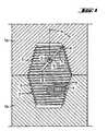
- Fig. 1 shows two electrodes 1a and 1b joined by a nipple 2.
- the electrodes 1a and 1b are provided at their ends with axial threaded sockets 3 in order to receive the threaded nipple 2.
- the nipple has the shape of a sawn-off cone.
- Reservoirs 4 containing the cement or cement components are located between the longitudinal center of the nipple and each end face thereof. These reservoirs are bored holes extending transversally into the nipple. According to the number of reservoirs and their depth, the hole diameters are selected in a way that the total volume of cement or cement components is able to fill 40 to 95 % of the clearance spaces between the threaded surfaces of the sockets and the nipple.
- linear grooves 5 were machined at an angle ⁇ into the nipple threads extending to the points A, B, and C, where ⁇ and the points A, B, and C are defined referring to the upper part of the nipple 2 depicted in Fig.1 :
- Figure 2 shows a nipple 2 according to this invention where two reservoirs 4 disembogue in a single groove 5.
- a nipple designed to connect electrodes of 600 mm in diameter was manufactured with four reservoirs, two in the upper and two in the lower part of the nipple, each of 25 mm diameter extending to a depth of 120 mm bored at a distance of 100 mm from the end faces of the nipple.
- the total volume of cement contained in these reservoirs is sufficient to fill about 80 % of the clearance spaces between the nipple and the threaded surfaces of the sockets.
- the width of these grooves can range between 3 to 10 mm having a depth equal to that of the threads root,
- the cement or cement components melt and flow out of the reservoirs through the grooves towards the clearance spaces of the threads, which are cut by and open into the grooves. In that way, the cement or cement components can reach 40 to 95 % of the clearance spaces of the threads.
- the present invention provides a system which permit to avoid losses of cement or cement components towards the adjacent end faces of the connected electrodes where they might be harmful or towards the spaces between the nipple and the bottoms of the sockets.
- the grooves 5 are terminated short of the longitudinal center of the nipple at their inner ends (point B) and short of the end faces of the nipple at their outer ends (point A) in such a way that at each slot end one and preferably several continuous threads are left in order to create a dam which will prevent the escape of the cement or cement components towards the non-desired spaces.
- Electrode joints based on nipples according to this invention showed decreased loosening during utilization in arc steel furnaces.
Landscapes
- Physics & Mathematics (AREA)
- Engineering & Computer Science (AREA)
- Plasma & Fusion (AREA)
- Discharge Heating (AREA)
- Electrical Discharge Machining, Electrochemical Machining, And Combined Machining (AREA)
- Physical Vapour Deposition (AREA)
Claims (9)
- Nipple (2) destiné à relier bout à bout, dans une connexion fixe et rigide, des électrodes cylindriques (1a, 1b) réalisées en carbone ou en graphite et comportant des cavités taraudées (3) à leurs extrémités axiales, le nipple étant muni, dans chacune de ses deux surfaces filetées, de trous de perçage utilisés comme réservoirs (4) pour un ou plusieurs composants de ciment,
caractérisé en ce qu'
il comporte, à l'endroit des sorties de réservoirs, une ou plusieurs rainures (5) s'étendant en travers des filets suivant des lignes dont les extrémités intérieures (B) se terminent avant le centre longitudinal du nipple (2), et leurs extrémités extérieures (A) et avant les faces d'extrémité du nipple (2), dans le but de laisser au moins un filet continu à chaque extrémité des rainures (5). - Niple (2) selon la revendication 1,
caractérisé en ce que
les rainures linéaires (5) sont usinées sous un angle α compris entre 0° et 60°, α étant l'angle compris entre le plan passant par l'axe longitudinal du nipple (2) et le centre (C) de la rainure (5), et le plan respectif passant par l'axe de la rainure (5). - Nipple (2) selon l'une des revendications 1 et 2,
caractérisé en ce que
la profondeur d'une rainure (5) est égale à la profondeur du fond des filets. - Nipple (2) selon l'une des revendications 1 à 3,
caractérisé en ce que
les trous percés dans chacune de ses deux surfaces filetées et utilisés comme réservoir (4) pour un ou plusieurs composants de ciment, s'étendent radicalement à l'intérieur du nipple (2) suivant un axe perpendiculaire à l'axe longitudinal du nipple (2), et les diamètres des trous se situent entre 10 et 30 millimètres. - Niple (2) selon l'une des revendications 1 à 4,
caractérisé en ce que
deux ou plusieurs réservoirs (4) débouchent dans une seule rainure. - Nipple (2) selon l'une des revendications 1 à 4,
caractérisé en ce que
deux rainures (5) se croisent l'une l'autre à l'endroit d'une seule sortie de réservoir (4). - Nipple (2) selon l'une des revendications 1 à 4,
caractérisé en ce que
plusieurs rainures (5) forment un système de rainures connectées. - Nipple (2) selon l'une des revendications 1 à 7,
caractérisé en ce que
le volume de ciment ou de composants de ciment placé dans le réservoir de trou de perçage (4) est suffisant pour remplir 40 % à 95 %, et de préférence 60 % à 80 %, des espaces de jeu entre les surfaces taraudées des cavités (3) et le nipple (2). - Utilisation de nipples (2) selon les revendications 1 à 8, pour relier des électrodes cylindriques (1a, 1b) réalisées en carbone ou en graphite à utiliser dans des fours à arc électrique.
Applications Claiming Priority (2)
| Application Number | Priority Date | Filing Date | Title |
|---|---|---|---|
| FR0450260 | 2004-02-13 | ||
| FR0450260A FR2866513B1 (fr) | 2004-02-13 | 2004-02-13 | Nipple pour electrode de four a arc |
Publications (2)
| Publication Number | Publication Date |
|---|---|
| EP1565040A1 EP1565040A1 (fr) | 2005-08-17 |
| EP1565040B1 true EP1565040B1 (fr) | 2008-05-07 |
Family
ID=34685081
Family Applications (1)
| Application Number | Title | Priority Date | Filing Date |
|---|---|---|---|
| EP05002919A Expired - Lifetime EP1565040B1 (fr) | 2004-02-13 | 2005-02-11 | Nipple destiné aux électrodes de four à arc |
Country Status (5)
| Country | Link |
|---|---|
| EP (1) | EP1565040B1 (fr) |
| AT (1) | ATE394904T1 (fr) |
| DE (1) | DE602005006447D1 (fr) |
| ES (1) | ES2305917T3 (fr) |
| FR (1) | FR2866513B1 (fr) |
Families Citing this family (2)
| Publication number | Priority date | Publication date | Assignee | Title |
|---|---|---|---|---|
| US7230969B2 (en) * | 2004-06-03 | 2007-06-12 | Ucar Carbon Company Inc. | Electrode joint locking system |
| DE102013216452B4 (de) | 2013-08-20 | 2016-12-01 | Sgl Carbon Se | Verbesserte Elektroden/Nippel-Verbindung |
Family Cites Families (7)
| Publication number | Priority date | Publication date | Assignee | Title |
|---|---|---|---|---|
| DE627108C (de) * | 1931-10-25 | 1936-03-09 | Siemens Planiawerke Akt Ges Fu | Verfahren zum Verbinden von Graphitelektroden |
| US2836806A (en) * | 1955-06-02 | 1958-05-27 | Union Carbide Corp | Conductive pad for electrode joint |
| US2969251A (en) * | 1960-02-15 | 1961-01-24 | Great Lakes Carbon Corp | Carbon electrode joint |
| FR1485912A (fr) * | 1965-06-30 | 1967-06-23 | Siemens Planiawerke Ag | Mastic pour la fixation d'une jonction par vissage entre deux électrodes de charbon |
| US4007324A (en) * | 1974-10-03 | 1977-02-08 | Airco, Inc. | Nipple for electrode joint |
| US4725161A (en) * | 1986-09-05 | 1988-02-16 | Union Carbide Corporation | Electrode joint |
| FR2692748B1 (fr) * | 1992-06-18 | 1998-07-17 | Savoie Electrodes Refract | Joint de raccordement d'electrodes de four electrique. |
-
2004
- 2004-02-13 FR FR0450260A patent/FR2866513B1/fr not_active Expired - Fee Related
-
2005
- 2005-02-11 AT AT05002919T patent/ATE394904T1/de not_active IP Right Cessation
- 2005-02-11 EP EP05002919A patent/EP1565040B1/fr not_active Expired - Lifetime
- 2005-02-11 ES ES05002919T patent/ES2305917T3/es not_active Expired - Lifetime
- 2005-02-11 DE DE602005006447T patent/DE602005006447D1/de not_active Expired - Fee Related
Also Published As
| Publication number | Publication date |
|---|---|
| DE602005006447D1 (de) | 2008-06-19 |
| ES2305917T3 (es) | 2008-11-01 |
| EP1565040A1 (fr) | 2005-08-17 |
| FR2866513B1 (fr) | 2006-08-04 |
| FR2866513A1 (fr) | 2005-08-19 |
| ATE394904T1 (de) | 2008-05-15 |
Similar Documents
| Publication | Publication Date | Title |
|---|---|---|
| US9313834B2 (en) | Electrode joint locking system | |
| US2510230A (en) | Electrode joint | |
| US20020141476A1 (en) | Electrode joint | |
| US2810117A (en) | Electrode connecting nipple | |
| US7016394B2 (en) | Male-female electrode joint | |
| EP0260529B2 (fr) | Joint d'électrode | |
| EP1565040B1 (fr) | Nipple destiné aux électrodes de four à arc | |
| US10237928B2 (en) | Long length electrodes | |
| CN109689938B (zh) | 具有插槽几何形状的阴极块 | |
| US5407290A (en) | Connecting joint for electric furnace electrodes | |
| US20020142645A1 (en) | Threaded pin for carbon electrodes | |
| US7103083B2 (en) | Optimized graphite electrode pin configuration | |
| US3419296A (en) | Electrode connecting pin and assembly | |
| US8165183B2 (en) | Joint design | |
| RU2107413C1 (ru) | Стыковое соединение электродов дуговой электропечи | |
| MX2008006285A (en) | Joint design |
Legal Events
| Date | Code | Title | Description |
|---|---|---|---|
| PUAI | Public reference made under article 153(3) epc to a published international application that has entered the european phase |
Free format text: ORIGINAL CODE: 0009012 |
|
| AK | Designated contracting states |
Kind code of ref document: A1 Designated state(s): AT BE BG CH CY CZ DE DK EE ES FI FR GB GR HU IE IS IT LI LT LU MC NL PL PT RO SE SI SK TR |
|
| AX | Request for extension of the european patent |
Extension state: AL BA HR LV MK YU |
|
| 17P | Request for examination filed |
Effective date: 20060217 |
|
| AKX | Designation fees paid |
Designated state(s): AT BE BG CH CY CZ DE DK EE ES FI FR GB GR HU IE IS IT LI LT LU MC NL PL PT RO SE SI SK TR |
|
| GRAP | Despatch of communication of intention to grant a patent |
Free format text: ORIGINAL CODE: EPIDOSNIGR1 |
|
| GRAS | Grant fee paid |
Free format text: ORIGINAL CODE: EPIDOSNIGR3 |
|
| GRAA | (expected) grant |
Free format text: ORIGINAL CODE: 0009210 |
|
| AK | Designated contracting states |
Kind code of ref document: B1 Designated state(s): AT BE BG CH CY CZ DE DK EE ES FI FR GB GR HU IE IS IT LI LT LU MC NL PL PT RO SE SI SK TR |
|
| REG | Reference to a national code |
Ref country code: GB Ref legal event code: FG4D |
|
| REG | Reference to a national code |
Ref country code: CH Ref legal event code: EP |
|
| REG | Reference to a national code |
Ref country code: IE Ref legal event code: FG4D Free format text: LANGUAGE OF EP DOCUMENT: FRENCH |
|
| REF | Corresponds to: |
Ref document number: 602005006447 Country of ref document: DE Date of ref document: 20080619 Kind code of ref document: P |
|
| PG25 | Lapsed in a contracting state [announced via postgrant information from national office to epo] |
Ref country code: SI Free format text: LAPSE BECAUSE OF FAILURE TO SUBMIT A TRANSLATION OF THE DESCRIPTION OR TO PAY THE FEE WITHIN THE PRESCRIBED TIME-LIMIT Effective date: 20080507 |
|
| PG25 | Lapsed in a contracting state [announced via postgrant information from national office to epo] |
Ref country code: FI Free format text: LAPSE BECAUSE OF FAILURE TO SUBMIT A TRANSLATION OF THE DESCRIPTION OR TO PAY THE FEE WITHIN THE PRESCRIBED TIME-LIMIT Effective date: 20080507 Ref country code: NL Free format text: LAPSE BECAUSE OF FAILURE TO SUBMIT A TRANSLATION OF THE DESCRIPTION OR TO PAY THE FEE WITHIN THE PRESCRIBED TIME-LIMIT Effective date: 20080507 |
|
| REG | Reference to a national code |
Ref country code: ES Ref legal event code: FG2A Ref document number: 2305917 Country of ref document: ES Kind code of ref document: T3 |
|
| NLV1 | Nl: lapsed or annulled due to failure to fulfill the requirements of art. 29p and 29m of the patents act | ||
| PG25 | Lapsed in a contracting state [announced via postgrant information from national office to epo] |
Ref country code: AT Free format text: LAPSE BECAUSE OF FAILURE TO SUBMIT A TRANSLATION OF THE DESCRIPTION OR TO PAY THE FEE WITHIN THE PRESCRIBED TIME-LIMIT Effective date: 20080507 Ref country code: PL Free format text: LAPSE BECAUSE OF FAILURE TO SUBMIT A TRANSLATION OF THE DESCRIPTION OR TO PAY THE FEE WITHIN THE PRESCRIBED TIME-LIMIT Effective date: 20080507 |
|
| PG25 | Lapsed in a contracting state [announced via postgrant information from national office to epo] |
Ref country code: IS Free format text: LAPSE BECAUSE OF FAILURE TO SUBMIT A TRANSLATION OF THE DESCRIPTION OR TO PAY THE FEE WITHIN THE PRESCRIBED TIME-LIMIT Effective date: 20080907 |
|
| PG25 | Lapsed in a contracting state [announced via postgrant information from national office to epo] |
Ref country code: CZ Free format text: LAPSE BECAUSE OF FAILURE TO SUBMIT A TRANSLATION OF THE DESCRIPTION OR TO PAY THE FEE WITHIN THE PRESCRIBED TIME-LIMIT Effective date: 20080507 Ref country code: SE Free format text: LAPSE BECAUSE OF FAILURE TO SUBMIT A TRANSLATION OF THE DESCRIPTION OR TO PAY THE FEE WITHIN THE PRESCRIBED TIME-LIMIT Effective date: 20080807 Ref country code: LT Free format text: LAPSE BECAUSE OF FAILURE TO SUBMIT A TRANSLATION OF THE DESCRIPTION OR TO PAY THE FEE WITHIN THE PRESCRIBED TIME-LIMIT Effective date: 20080507 Ref country code: PT Free format text: LAPSE BECAUSE OF FAILURE TO SUBMIT A TRANSLATION OF THE DESCRIPTION OR TO PAY THE FEE WITHIN THE PRESCRIBED TIME-LIMIT Effective date: 20081007 Ref country code: DK Free format text: LAPSE BECAUSE OF FAILURE TO SUBMIT A TRANSLATION OF THE DESCRIPTION OR TO PAY THE FEE WITHIN THE PRESCRIBED TIME-LIMIT Effective date: 20080507 |
|
| PG25 | Lapsed in a contracting state [announced via postgrant information from national office to epo] |
Ref country code: BE Free format text: LAPSE BECAUSE OF FAILURE TO SUBMIT A TRANSLATION OF THE DESCRIPTION OR TO PAY THE FEE WITHIN THE PRESCRIBED TIME-LIMIT Effective date: 20080507 Ref country code: RO Free format text: LAPSE BECAUSE OF FAILURE TO SUBMIT A TRANSLATION OF THE DESCRIPTION OR TO PAY THE FEE WITHIN THE PRESCRIBED TIME-LIMIT Effective date: 20080507 Ref country code: SK Free format text: LAPSE BECAUSE OF FAILURE TO SUBMIT A TRANSLATION OF THE DESCRIPTION OR TO PAY THE FEE WITHIN THE PRESCRIBED TIME-LIMIT Effective date: 20080507 |
|
| PLBE | No opposition filed within time limit |
Free format text: ORIGINAL CODE: 0009261 |
|
| STAA | Information on the status of an ep patent application or granted ep patent |
Free format text: STATUS: NO OPPOSITION FILED WITHIN TIME LIMIT |
|
| 26N | No opposition filed |
Effective date: 20090210 |
|
| PG25 | Lapsed in a contracting state [announced via postgrant information from national office to epo] |
Ref country code: BG Free format text: LAPSE BECAUSE OF FAILURE TO SUBMIT A TRANSLATION OF THE DESCRIPTION OR TO PAY THE FEE WITHIN THE PRESCRIBED TIME-LIMIT Effective date: 20080807 Ref country code: EE Free format text: LAPSE BECAUSE OF FAILURE TO SUBMIT A TRANSLATION OF THE DESCRIPTION OR TO PAY THE FEE WITHIN THE PRESCRIBED TIME-LIMIT Effective date: 20080507 |
|
| PGFP | Annual fee paid to national office [announced via postgrant information from national office to epo] |
Ref country code: ES Payment date: 20090220 Year of fee payment: 5 |
|
| PGFP | Annual fee paid to national office [announced via postgrant information from national office to epo] |
Ref country code: DE Payment date: 20090228 Year of fee payment: 5 |
|
| PG25 | Lapsed in a contracting state [announced via postgrant information from national office to epo] |
Ref country code: IT Free format text: LAPSE BECAUSE OF FAILURE TO SUBMIT A TRANSLATION OF THE DESCRIPTION OR TO PAY THE FEE WITHIN THE PRESCRIBED TIME-LIMIT Effective date: 20080507 |
|
| PG25 | Lapsed in a contracting state [announced via postgrant information from national office to epo] |
Ref country code: MC Free format text: LAPSE BECAUSE OF NON-PAYMENT OF DUE FEES Effective date: 20090228 |
|
| REG | Reference to a national code |
Ref country code: CH Ref legal event code: PL |
|
| GBPC | Gb: european patent ceased through non-payment of renewal fee |
Effective date: 20090211 |
|
| PG25 | Lapsed in a contracting state [announced via postgrant information from national office to epo] |
Ref country code: LI Free format text: LAPSE BECAUSE OF NON-PAYMENT OF DUE FEES Effective date: 20090228 Ref country code: CH Free format text: LAPSE BECAUSE OF NON-PAYMENT OF DUE FEES Effective date: 20090228 |
|
| PGFP | Annual fee paid to national office [announced via postgrant information from national office to epo] |
Ref country code: FR Payment date: 20090213 Year of fee payment: 5 |
|
| REG | Reference to a national code |
Ref country code: IE Ref legal event code: MM4A |
|
| PG25 | Lapsed in a contracting state [announced via postgrant information from national office to epo] |
Ref country code: IE Free format text: LAPSE BECAUSE OF NON-PAYMENT OF DUE FEES Effective date: 20090211 |
|
| PG25 | Lapsed in a contracting state [announced via postgrant information from national office to epo] |
Ref country code: GB Free format text: LAPSE BECAUSE OF NON-PAYMENT OF DUE FEES Effective date: 20090211 |
|
| PG25 | Lapsed in a contracting state [announced via postgrant information from national office to epo] |
Ref country code: GR Free format text: LAPSE BECAUSE OF FAILURE TO SUBMIT A TRANSLATION OF THE DESCRIPTION OR TO PAY THE FEE WITHIN THE PRESCRIBED TIME-LIMIT Effective date: 20080808 |
|
| REG | Reference to a national code |
Ref country code: FR Ref legal event code: ST Effective date: 20101029 |
|
| PG25 | Lapsed in a contracting state [announced via postgrant information from national office to epo] |
Ref country code: FR Free format text: LAPSE BECAUSE OF NON-PAYMENT OF DUE FEES Effective date: 20100301 |
|
| PG25 | Lapsed in a contracting state [announced via postgrant information from national office to epo] |
Ref country code: DE Free format text: LAPSE BECAUSE OF NON-PAYMENT OF DUE FEES Effective date: 20100901 |
|
| REG | Reference to a national code |
Ref country code: ES Ref legal event code: FD2A Effective date: 20110308 |
|
| PG25 | Lapsed in a contracting state [announced via postgrant information from national office to epo] |
Ref country code: LU Free format text: LAPSE BECAUSE OF NON-PAYMENT OF DUE FEES Effective date: 20090211 |
|
| PG25 | Lapsed in a contracting state [announced via postgrant information from national office to epo] |
Ref country code: HU Free format text: LAPSE BECAUSE OF FAILURE TO SUBMIT A TRANSLATION OF THE DESCRIPTION OR TO PAY THE FEE WITHIN THE PRESCRIBED TIME-LIMIT Effective date: 20081108 |
|
| PG25 | Lapsed in a contracting state [announced via postgrant information from national office to epo] |
Ref country code: ES Free format text: LAPSE BECAUSE OF NON-PAYMENT OF DUE FEES Effective date: 20110307 |
|
| PG25 | Lapsed in a contracting state [announced via postgrant information from national office to epo] |
Ref country code: TR Free format text: LAPSE BECAUSE OF FAILURE TO SUBMIT A TRANSLATION OF THE DESCRIPTION OR TO PAY THE FEE WITHIN THE PRESCRIBED TIME-LIMIT Effective date: 20080507 |
|
| PG25 | Lapsed in a contracting state [announced via postgrant information from national office to epo] |
Ref country code: CY Free format text: LAPSE BECAUSE OF FAILURE TO SUBMIT A TRANSLATION OF THE DESCRIPTION OR TO PAY THE FEE WITHIN THE PRESCRIBED TIME-LIMIT Effective date: 20080507 Ref country code: ES Free format text: LAPSE BECAUSE OF NON-PAYMENT OF DUE FEES Effective date: 20100212 |