EP1565008B1 - Reproducing apparatus - Google Patents
Reproducing apparatus Download PDFInfo
- Publication number
- EP1565008B1 EP1565008B1 EP20050250737 EP05250737A EP1565008B1 EP 1565008 B1 EP1565008 B1 EP 1565008B1 EP 20050250737 EP20050250737 EP 20050250737 EP 05250737 A EP05250737 A EP 05250737A EP 1565008 B1 EP1565008 B1 EP 1565008B1
- Authority
- EP
- European Patent Office
- Prior art keywords
- data
- error
- encoded
- picture
- ecc
- Prior art date
- Legal status (The legal status is an assumption and is not a legal conclusion. Google has not performed a legal analysis and makes no representation as to the accuracy of the status listed.)
- Expired - Fee Related
Links
Images


Classifications
-
- H—ELECTRICITY
- H04—ELECTRIC COMMUNICATION TECHNIQUE
- H04N—PICTORIAL COMMUNICATION, e.g. TELEVISION
- H04N9/00—Details of colour television systems
- H04N9/79—Processing of colour television signals in connection with recording
- H04N9/87—Regeneration of colour television signals
- H04N9/88—Signal drop-out compensation
- H04N9/888—Signal drop-out compensation for signals recorded by pulse code modulation
-
- H—ELECTRICITY
- H04—ELECTRIC COMMUNICATION TECHNIQUE
- H04N—PICTORIAL COMMUNICATION, e.g. TELEVISION
- H04N5/00—Details of television systems
- H04N5/76—Television signal recording
- H04N5/78—Television signal recording using magnetic recording
- H04N5/782—Television signal recording using magnetic recording on tape
- H04N5/7824—Television signal recording using magnetic recording on tape with rotating magnetic heads
- H04N5/7826—Television signal recording using magnetic recording on tape with rotating magnetic heads involving helical scanning of the magnetic tape
- H04N5/78263—Television signal recording using magnetic recording on tape with rotating magnetic heads involving helical scanning of the magnetic tape for recording on tracks inclined relative to the direction of movement of the tape
- H04N5/78266—Television signal recording using magnetic recording on tape with rotating magnetic heads involving helical scanning of the magnetic tape for recording on tracks inclined relative to the direction of movement of the tape using more than one track for the recording of one television field or frame, i.e. segmented recording
-
- H—ELECTRICITY
- H04—ELECTRIC COMMUNICATION TECHNIQUE
- H04N—PICTORIAL COMMUNICATION, e.g. TELEVISION
- H04N9/00—Details of colour television systems
- H04N9/79—Processing of colour television signals in connection with recording
- H04N9/80—Transformation of the television signal for recording, e.g. modulation, frequency changing; Inverse transformation for playback
- H04N9/804—Transformation of the television signal for recording, e.g. modulation, frequency changing; Inverse transformation for playback involving pulse code modulation of the colour picture signal components
- H04N9/8042—Transformation of the television signal for recording, e.g. modulation, frequency changing; Inverse transformation for playback involving pulse code modulation of the colour picture signal components involving data reduction
Definitions
- the present invention relates to a reproducing apparatus, and more specifically to processing of error data in encoded image data.
- An apparatus for encoding video data using an encoding technique, such as MPEG (moving picture expert group), and recording and reproducing the encoded data is disclosed in, for example, Japanese Patent Laid-Open No. 2003-46944 (corresponding U.S. Published Application No. 2003/26590 ).
- this recording and reproducing apparatus if reproduced encoded data is missing, the missing data is substituted with encoded data of a specific color, such as black or gray.
- this apparatus outputs a black or gray picture for missing data, and gives an undesirable image to the user.
- EP 0588586 discloses decoding apparatus uncorrectable errors are replaced by previously decoded video signals, while EP1051035 relates to a data packing scheme and dscloses a reproducing apparatus in which a concealing circuit corrects data encoded according to such a scheme by substituting with data from a preceding frame.
- the present invention provides a system for preventing decoding failure if missing data, such as an error, occurs in an encoded stream to give a desirable reproduced screen.
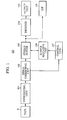
- Fig. 1 is a block diagram of a reproducing apparatus according to the present invention.
- Fig. 2 is a diagram showing the track format of a tape.
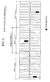
- Fig. 3 is a diagram showing the format of data recorded in each track.
- Fig. 4 is a flowchart showing a reproducing process.
- Fig. 5 is a flowchart showing an error data substitution process.
- Fig. 1 is a block diagram of a reproducing apparatus 100 according to the present invention.
- the apparatus 100 shown in Fig. 1 reproduces an MPEG-encoded video stream from multiple tracks on a tape T.
- a data stream is encoded using the following three picture coding types frame-by-frame in predetermined order: I picture (intra-coded picture) coding using only image data within the same frame, P picture (predictive-coded picture) coding with motion compensation based on a preceding frame picture, and B picture (bi-directionally-predictive-coded picture) coding with motion compensation using the image data of the preceding and succeeding frames.
- a data stream is encoded in units of a predetermined number of frames starting from a given I picture to the next I picture, called a GOP (Group Of Pictures). I pictures are coded using only image data within the same frame.
- P and B pictures difference data from a reference frame is encoded, and the amount of encoded data changes from one frame to another.
- image data is encoded and recorded so as to have substantially a predetermined data rate of several Mbps.
- a reproducing unit 101 reproduces the recorded encoded image data, and outputs the reproduced image data to an error correcting unit 102.
- the error correcting unit 102 decodes the reproduced data according to error correction coding that the recorded image data is subjected to, and corrects for a transmission error in the reproduced data. If the reproduced data contains an uncorrectable error, the error correcting unit 102 informs a control unit 107 of the uncorrectable error.
- Fig. 2 illustrates a format of the data recorded in the tape T.
- data is interleaved in units of 16 tracks, and the interleaved data is subjected to error correction coding to add an outer code.
- a unit of 16 tracks is referred to as an "ECC unit".
- the error correcting unit 102 performs error correction decoding in units of ECC units. In this case, an uncorrectable error can occur in units of ECC units, and correct reproduced data may be missing.
- system data is inserted every predetermined number of frames.
- the system data is data for editing the encoded image and audio data recorded in the tape T, and includes a DTS (decoding time stamp) and VBV_Delay value of the encoded data.
- a GOP consists of 15 frames in order of I, B, B, P, B, B, P, B, B, P, B, B, P, B, B, B pictures, and system data is inserted every 3 frames. In one GOP, therefore, system data is multiplexed before the I picture and the P pictures.
- the DTS is a time stamp for synchronizing MPEG data when decoded.
- MPEG data is actually decoded.
- MPEG-2 the value of a counter that counts a 27-MHz system clock is used as a reference time.
- the VBV_Delay value indicates the time for which encoded data of one frame resides in a VBV buffer that is specified by MPEG when decoded.
- Fig. 3 illustrates the structure of data recorded in each track shown in Fig. 2 .
- data recorded in one track consists of 139 sync blocks 0 to 138.
- Each sync block is constituted by Sync, ID0, ID1, ID2, encoded data or outer parity, and inner parity.
- ID0 to ID2 include track pair number information indicating the track position in one ECC block, and sync block number information of one track.
- the outer parity shown in Fig. 3 is added by calculation to interleaved data of 16 tracks.
- the error correcting unit 102 performs error correction decoding in units of 16 tracks using the outer parity and the inner parity.
- the data corrected by the error correcting unit 102 is written in a stream buffer 103.
- the stream buffer 103 has a storage capacity more than the amount of data specified by MPEG.
- a buffer managing unit 106 manages writing and reading of data to and from the stream buffer 103 and other processing under the control of a control unit 107.
- the encoded data stored in the stream buffer 103 is sent to a decoder 104 at a timing determined based on the DTS, and is then decoded.
- the decoded image and audio data is output to an external monitor or the like from an output unit 105.
- the encoded data stored in the stream buffer 103 is also output to a digital interface (DIF) 108.
- the DIF 108 outputs the MPEG stream data output from the stream buffer 103 to an external decoder or the like via a transmission path according to a digital interface standard, such as IEEE 1394.
- Fig. 4 is a flowchart showing uncorrectable-error control performed by the control unit 107.
- a reproduced ECC unit includes system data (step S401).
- each of the ECC units 1 to 3 includes system data.
- image data is encoded so that the amount of data changes depending upon the frame, and therefore system data is not always contained in an ECC unit.
- the control unit 107 determines whether or not an error flag indicating the presence of error data in any preceding reproduced ECC unit is set (step S402). If the error flag is not set, it is determined that no preceding ECC unit data containing an uncorrectable error exists or a substitution procedure described below has been performed, and the reproduced system data is stored in a system data backup memory of the buffer managing unit 106 (step S409).
- the backup memory of the buffer managing unit 106 includes a first memory area for storing the system data detected immediately before an ECC unit containing an uncorrectable error, and a second memory area for storing the system data multiplexed at the head of the GOP reproduced immediately after an ECC unit containing an error. If it is determined in step S402 that the error flag is not set, the first memory area is overwritten each time system data is detected, and the detected system data is stored in the first memory area.
- the ECC unit 1 contains no error, and includes system data.
- the system data in the ECC unit 1 is first stored in the first memory area. After the system data is stored in the first memory area (step S409), the process proceeds to step S407.
- step S407 it is determined whether or not the currently reproduced ECC unit contains an uncorrectable error.
- the ECC unit 1 contains no error. Thus, the process ends.
- step S407 it is determined whether or not the ECC unit 2 contains an uncorrectable error. Since the ECC unit 2 contains an error, the process proceeds to step S408. In step S408, an internal error flag indicating that the reproduced ECC unit contains an error is set. Then, the process ends.
- step S401 Since the ECC unit 3 contains no uncorrectable error, system data is detected in step S401. Then, an error flag is checked to determine whether or not any preceding ECC unit contains an error (step S402). In this example, the ECC unit 2 contains an uncorrectable error, and the error flag is set. Thus, the process proceeds to step S403.
- step S403 it is determined whether or not the system data detected in step S401 is system data multiplexed at the head of a GOP in the MPEG stream. If it is system data multiplexed at the head of a GOP, the detected system data is stored in the second memory area of the buffer managing unit 106 (S404). In this example, it is assumed that the system data in the ECC unit 3 resides at the head of a GOP, and the system data in the ECC unit 3 is stored in the second memory area.
- the system data in the ECC unit 1 is stored in the first memory area of the buffer managing unit 106, and the system data in the ECC unit 3 is stored in the second memory area.
- the system data stored in the first and second memory areas are used to perform a substitution procedure described below on the data in the ECC unit 2 containing an uncorrectable error and the preceding and succeeding data (step S405).
- the error flag is reset, and the process proceeds to step S407. It is determined in step S407 that the ECC unit 3 contains no uncorrectable error, and then the process ends.
- Fig. 5 is a flowchart showing the substitution procedure in step S405 shown in Fig. 4 .
- the system data detected immediately before an ECC unit containing an uncorrectable error and the system data at the head of the GOP detected immediately after the ECC unit are backed up.
- the difference between the values of the DTSs in these system data is determined (step S501), and a series of frames between these system data, including the ECC unit containing the error, is detected (step S502).
- number of frames difference between DTSs in the system data before and after the error / clock speed ⁇ frames per second
- number of frames difference between DTSs in the system data before and after the error / 27 ⁇ 10 6 ⁇ 30
- the buffer managing unit 106 uses data indicating that the difference between the current data and data immediately previous to the current data is 0 in an MPEG system (hereinafter referred to as "Copy-Picture data").
- the MPEG stream data stored in the stream buffer 103 that resides between the system data in the ECC unit 1 and the system data in the ECC unit 3 is substituted with the Copy-Picture data corresponding to the number of frames given in the above-noted equation.
- the decoder 104 outputs the decoded image data of the reference frame.
- the reproduced image of the Copy-Picture data is therefore the same as the image of the reference frame.
- the Copy-Picture data is MPEG data indicating zero difference, and has a small amount of data. Thus, insertion of the Copy-Picture data can cause an underflow of the VBV buffer.
- the amount of data for the error period is determined, and stuffing data (or dummy data) is generated by subtracting the amount of Copy-Picture data from the determined amount of data.
- the generated stuffing data is put in place of the MPEG data for the error period stored in the stream buffer 103 (steps S503 and S504).
- the period between the system data before and after an ECC unit containing an uncorrectable error is regarded as an error period.
- the data corresponding to the error period is substituted with the Copy-Picture data, and the stuffing data is further inserted to prevent the VBV buffer specified by MPEG from causing an overflow before and after the Copy-Picture data.
- the reproduced image for the error period can be displayed by freezing the preceding image on the screen.
- the error data in the MPEG stream is substituted with the Copy-Picture data, thus allowing even an external decoder to show a screen on which the preceding image is frozen during the error period when the MPEG stream is output from the DIF 108, which gives a better viewing screen to the user.
- the ECC unit 3 that follows the error period includes P picture data and B picture data
- the ECC unit 2 containing an error may include a reference picture data of the P picture data and the B picture data.
- system data is multiplexed before the I picture and P pictures in one GOP.
- system data may be multiplexed before the I picture that resides at the head of a GOP.
- the data of the GOP including image data of an ECC unit containing an uncorrectable error is substituted with the Copy-Picture data, and the number of pictures of the Copy-Picture data is equal to the number of pictures of one GOP.
- the present invention is applied to an apparatus that reproduces an MPEG stream recorded on a tape.
- the present invention may also be applicable to reproduction of data encoded using a coding technique in which the amount of data changes depending upon the frame, such as MPEG.
- a picture including error data is substituted with encoded data so as to output the same image as a picture immediately before the picture, thus giving a better reproduced picture when decoded.
Description
- The present invention relates to a reproducing apparatus, and more specifically to processing of error data in encoded image data.
- An apparatus for encoding video data using an encoding technique, such as MPEG (moving picture expert group), and recording and reproducing the encoded data is disclosed in, for example, Japanese Patent Laid-Open No.
2003-46944 U.S. Published Application No. 2003/26590 ). In this recording and reproducing apparatus, if reproduced encoded data is missing, the missing data is substituted with encoded data of a specific color, such as black or gray. However, this apparatus outputs a black or gray picture for missing data, and gives an undesirable image to the user. Moreover, if black or gray data is merely inserted in an encoded stream, the resulting stream is not verified with the buffer model (VBV (video buffering verifier) buffer) that is specified by MPEG, and a decoder may cause decoding failure due to underflow or overflow of data stored in a buffer memory.EP 0588586 discloses decoding apparatus uncorrectable errors are replaced by previously decoded video signals, whileEP1051035 relates to a data packing scheme and dscloses a reproducing apparatus in which a concealing circuit corrects data encoded according to such a scheme by substituting with data from a preceding frame. - In order to overcome the foregoing problems, the present invention provides a system for preventing decoding failure if missing data, such as an error, occurs in an encoded stream to give a desirable reproduced screen.
- In an aspect of the present invention, a reproducing.apparatus according to
Claim 1 is provided. - Further features and advantages of the present invention will become apparent from the following description of exemplary embodiments with reference to the attached drawings.
-
Fig. 1 is a block diagram of a reproducing apparatus according to the present invention. -
Fig. 2 is a diagram showing the track format of a tape. -
Fig. 3 is a diagram showing the format of data recorded in each track. -
Fig. 4 is a flowchart showing a reproducing process. -
Fig. 5 is a flowchart showing an error data substitution process. - Embodiments of the present invention will be described.
-
Fig. 1 is a block diagram of a reproducingapparatus 100 according to the present invention. - The
apparatus 100 shown inFig. 1 reproduces an MPEG-encoded video stream from multiple tracks on a tape T. In MPEG, a data stream is encoded using the following three picture coding types frame-by-frame in predetermined order:
I picture (intra-coded picture) coding using only image data within the same frame, P picture (predictive-coded picture) coding with motion compensation based on a preceding frame picture, and B picture (bi-directionally-predictive-coded picture) coding with motion compensation using the image data of the preceding and succeeding frames. In MPEG, a data stream is encoded in units of a predetermined number of frames starting from a given I picture to the next I picture, called a GOP (Group Of Pictures). I pictures are coded using only image data within the same frame. In P and B pictures, difference data from a reference frame is encoded, and the amount of encoded data changes from one frame to another. - In the present embodiment, image data is encoded and recorded so as to have substantially a predetermined data rate of several Mbps.
- In
Fig. 1 , a reproducingunit 101 reproduces the recorded encoded image data, and outputs the reproduced image data to anerror correcting unit 102. Theerror correcting unit 102 decodes the reproduced data according to error correction coding that the recorded image data is subjected to, and corrects for a transmission error in the reproduced data. If the reproduced data contains an uncorrectable error, theerror correcting unit 102 informs acontrol unit 107 of the uncorrectable error. -
Fig. 2 illustrates a format of the data recorded in the tape T. - As shown in
Fig. 2 , in the present embodiment, data is interleaved in units of 16 tracks, and the interleaved data is subjected to error correction coding to add an outer code. A unit of 16 tracks is referred to as an "ECC unit". Theerror correcting unit 102 performs error correction decoding in units of ECC units. In this case, an uncorrectable error can occur in units of ECC units, and correct reproduced data may be missing. - In the present embodiment, in addition to the MPEG-encoded image and audio data, system data is inserted every predetermined number of frames. The system data is data for editing the encoded image and audio data recorded in the tape T, and includes a DTS (decoding time stamp) and VBV_Delay value of the encoded data. In the present embodiment, a GOP consists of 15 frames in order of I, B, B, P, B, B, P, B, B, P, B, B, P, B, B pictures, and system data is inserted every 3 frames. In one GOP, therefore, system data is multiplexed before the I picture and the P pictures.
- The DTS is a time stamp for synchronizing MPEG data when decoded. When the value of a decoder counter that counts a reference time coincides with the value of the DTS, MPEG data is actually decoded. In MPEG-2, the value of a counter that counts a 27-MHz system clock is used as a reference time.
- The VBV_Delay value indicates the time for which encoded data of one frame resides in a VBV buffer that is specified by MPEG when decoded.
-
Fig. 3 illustrates the structure of data recorded in each track shown inFig. 2 . - As shown in
Fig. 3 , data recorded in one track consists of 139sync blocks 0 to 138. Each sync block is constituted by Sync, ID0, ID1, ID2, encoded data or outer parity, and inner parity. ID0 to ID2 include track pair number information indicating the track position in one ECC block, and sync block number information of one track. - The outer parity shown in
Fig. 3 is added by calculation to interleaved data of 16 tracks. Theerror correcting unit 102 performs error correction decoding in units of 16 tracks using the outer parity and the inner parity. - The data corrected by the
error correcting unit 102 is written in astream buffer 103. Thestream buffer 103 has a storage capacity more than the amount of data specified by MPEG. Abuffer managing unit 106 manages writing and reading of data to and from thestream buffer 103 and other processing under the control of acontrol unit 107. - The encoded data stored in the
stream buffer 103 is sent to adecoder 104 at a timing determined based on the DTS, and is then decoded. The decoded image and audio data is output to an external monitor or the like from anoutput unit 105. The encoded data stored in thestream buffer 103 is also output to a digital interface (DIF) 108. The DIF 108 outputs the MPEG stream data output from thestream buffer 103 to an external decoder or the like via a transmission path according to a digital interface standard, such as IEEE 1394. - Processing of error data in reproduced data by the reproducing
apparatus 100 will now be described. In the following description, encoded data is recorded in the manner shown inFig. 2 , and the data in theECC unit 2 contains an uncorrectable error. -
Fig. 4 is a flowchart showing uncorrectable-error control performed by thecontrol unit 107. - In
Fig. 4 , first, it is determined whether or not a reproduced ECC unit includes system data (step S401). InFig. 2 , each of theECC units 1 to 3 includes system data. In the present embodiment, as described above, image data is encoded so that the amount of data changes depending upon the frame, and therefore system data is not always contained in an ECC unit. - If no error detection flag is output from the
error correcting unit 102 and if an ECC unit reproduced by thebuffer managing unit 106 includes system data, thecontrol unit 107 determines whether or not an error flag indicating the presence of error data in any preceding reproduced ECC unit is set (step S402). If the error flag is not set, it is determined that no preceding ECC unit data containing an uncorrectable error exists or a substitution procedure described below has been performed, and the reproduced system data is stored in a system data backup memory of the buffer managing unit 106 (step S409). - The backup memory of the
buffer managing unit 106 includes a first memory area for storing the system data detected immediately before an ECC unit containing an uncorrectable error, and a second memory area for storing the system data multiplexed at the head of the GOP reproduced immediately after an ECC unit containing an error. If it is determined in step S402 that the error flag is not set, the first memory area is overwritten each time system data is detected, and the detected system data is stored in the first memory area. - In
Fig. 2 , theECC unit 1 contains no error, and includes system data. Thus, the system data in theECC unit 1 is first stored in the first memory area. After the system data is stored in the first memory area (step S409), the process proceeds to step S407. - In step S407, it is determined whether or not the currently reproduced ECC unit contains an uncorrectable error. In
Fig. 2 , theECC unit 1 contains no error. Thus, the process ends. - Data processing in the
ECC unit 2 will now be described. - Since the
ECC unit 2 contains an uncorrectable error, system data cannot be detected in step S401. Then, the process proceeds to step S407. In step S407, it is determined whether or not theECC unit 2 contains an uncorrectable error. Since theECC unit 2 contains an error, the process proceeds to step S408. In step S408, an internal error flag indicating that the reproduced ECC unit contains an error is set. Then, the process ends. - A process for reproducing the
ECC unit 3 containing no error that follows theECC unit 2 containing an error will now be described. - Since the
ECC unit 3 contains no uncorrectable error, system data is detected in step S401. Then, an error flag is checked to determine whether or not any preceding ECC unit contains an error (step S402). In this example, theECC unit 2 contains an uncorrectable error, and the error flag is set. Thus, the process proceeds to step S403. In step S403, it is determined whether or not the system data detected in step S401 is system data multiplexed at the head of a GOP in the MPEG stream. If it is system data multiplexed at the head of a GOP, the detected system data is stored in the second memory area of the buffer managing unit 106 (S404). In this example, it is assumed that the system data in theECC unit 3 resides at the head of a GOP, and the system data in theECC unit 3 is stored in the second memory area. - At this time, the system data in the
ECC unit 1 is stored in the first memory area of thebuffer managing unit 106, and the system data in theECC unit 3 is stored in the second memory area. The system data stored in the first and second memory areas are used to perform a substitution procedure described below on the data in theECC unit 2 containing an uncorrectable error and the preceding and succeeding data (step S405). In step S406, the error flag is reset, and the process proceeds to step S407. It is determined in step S407 that theECC unit 3 contains no uncorrectable error, and then the process ends. -
Fig. 5 is a flowchart showing the substitution procedure in step S405 shown inFig. 4 . - In the present embodiment, as described above, the system data detected immediately before an ECC unit containing an uncorrectable error and the system data at the head of the GOP detected immediately after the ECC unit are backed up. The difference between the values of the DTSs in these system data is determined (step S501), and a series of frames between these system data, including the ECC unit containing the error, is detected (step S502).
- The number of frames between the system data detected immediately before and after the ECC unit containing the error is given as follows:


- In the present embodiment, the
buffer managing unit 106 uses data indicating that the difference between the current data and data immediately previous to the current data is 0 in an MPEG system (hereinafter referred to as "Copy-Picture data"). The MPEG stream data stored in thestream buffer 103 that resides between the system data in theECC unit 1 and the system data in theECC unit 3 is substituted with the Copy-Picture data corresponding to the number of frames given in the above-noted equation. When the Copy-Picture data is input to thedecoder 104, thedecoder 104 outputs the decoded image data of the reference frame. The reproduced image of the Copy-Picture data is therefore the same as the image of the reference frame. - The Copy-Picture data is MPEG data indicating zero difference, and has a small amount of data. Thus, insertion of the Copy-Picture data can cause an underflow of the VBV buffer.
- In order to avoid such an underflow problem, the amount of data for the error period is determined, and stuffing data (or dummy data) is generated by subtracting the amount of Copy-Picture data from the determined amount of data. The generated stuffing data is put in place of the MPEG data for the error period stored in the stream buffer 103 (steps S503 and S504).
- The amount of stuffing data is determined as follows:

- The period between the system data before and after an ECC unit containing an uncorrectable error is regarded as an error period. The data corresponding to the error period is substituted with the Copy-Picture data, and the stuffing data is further inserted to prevent the VBV buffer specified by MPEG from causing an overflow before and after the Copy-Picture data. Thus, if an uncorrectable error occurs, the reproduced image for the error period can be displayed by freezing the preceding image on the screen.
- The error data in the MPEG stream is substituted with the Copy-Picture data, thus allowing even an external decoder to show a screen on which the preceding image is frozen during the error period when the MPEG stream is output from the
DIF 108, which gives a better viewing screen to the user. - In
Fig. 2 , theECC unit 3 that follows the error period includes P picture data and B picture data, and theECC unit 2 containing an error may include a reference picture data of the P picture data and the B picture data. - In the present embodiment, all data from the system data reproduced after an ECC unit containing an uncorrectable error to the system data multiplexed at the head of a GOP is substituted with the Copy-Picture data. This prevents the ECC unit data reproduced after an ECC unit containing an error from being incorrectly decoded. In MPEG data, as described above, an I picture resides at the head of a GOP. Thus, the data from the head of the GOP can be correctly decoded.
- In the present embodiment, system data is multiplexed before the I picture and P pictures in one GOP. However, the present invention is not limited thereto, and system data may be multiplexed before the I picture that resides at the head of a GOP.
- In this case, the data of the GOP including image data of an ECC unit containing an uncorrectable error is substituted with the Copy-Picture data, and the number of pictures of the Copy-Picture data is equal to the number of pictures of one GOP.
- In the illustrated embodiment, the present invention is applied to an apparatus that reproduces an MPEG stream recorded on a tape. The present invention may also be applicable to reproduction of data encoded using a coding technique in which the amount of data changes depending upon the frame, such as MPEG.
- According to the present embodiment, therefore, a picture including error data is substituted with encoded data so as to output the same image as a picture immediately before the picture, thus giving a better reproduced picture when decoded.
- While the present invention has been described with reference to exemplary embodiments, it is to be understood that the invention is not limited to the disclosed embodiments.
Claims (3)
- A reproduction apparatus (100) comprising:reproduction means (101) for reproducing, from a recording medium, an encoded video data sequence divided into consecutive error correcting code (ECC) units, the encoded video data sequence including intra-coded pictures encoded using only image data within the same frame picture (I-picture), predictive-coded pictures encoded with motion compensation based on a preceding frame picture (P-picture), and bidirectionally predictive coded pictures encoded with motion compensation based on preceding and succeeding frame pictures (B-picture); anderror correcting means (102) for correcting correctable errors in the ECC units reproduced by the reproducing means if the ECC units contain correctable errors, and for outputting error flag information indicating existence of an uncorrectable error in the ECC units if the ECC units contain uncorrectable errors;characterised in thatthe I-pictures and/or the P-pictures comprise system data, the system data including a time stamp (DTS) and information indicating the time for which encoded data of one frame resides in a VBV buffer (VBV_Delay); andthe reproducing apparatus further comprising control means (107) configured todetect the error flag information from the error correcting means;obtain the time stamp immediately before an ECC unit containing an uncorrectable error and the time stamp immediately after the ECC unit containing the uncorrectable error;determine the number of pictures in the encoded video data sequence affected by the uncorrectable error based on the obtained time stamps;substitute the encoded video data sequence of the number of pictures affected by the uncorrectable error with predetermined encoded data, the predetermined encoded data indicating that difference data from a reference picture is zero; andoutput the encoded video data sequence including the substituted predetermined encoded data to a decoder for decoding, so as to obtain a frozen image for a period affected by the uncorrectable error.
- A reproducing apparatus (100) according to Claim 1, wherein the the control means is further configured to
obtain the VBV_Delay immediately before an ECC unit containing an uncorrectable error and the VBV_Delay immediately after the ECC unit containing the uncorrectable error;
determine an amount of dummy data based on the time stamps, the VBV_Delay values and the amount of data of the predetermined encoded data; and
substitute the encoded video data sequence of the number of pictures affected by the uncorrectable error with the predetermined encoded data and the dummy data, so as to avoid buffer underflow when decoding. - A reproducing apparatus (100) according to Claim 1 or Claim 2, further comprising external outputting means (105) for receiving the encoded video data sequence including the substituted predetermined encoded data from the control means (107) and for outputting the encoded video data sequence including the substituted predetermined encoded data to outside of the reproducing apparatus (100).
Applications Claiming Priority (2)
| Application Number | Priority Date | Filing Date | Title |
|---|---|---|---|
| JP2004036813 | 2004-02-13 | ||
| JP2004036813A JP2005229395A (en) | 2004-02-13 | 2004-02-13 | Reproducing arrangement |
Publications (3)
| Publication Number | Publication Date |
|---|---|
| EP1565008A2 EP1565008A2 (en) | 2005-08-17 |
| EP1565008A3 EP1565008A3 (en) | 2010-12-08 |
| EP1565008B1 true EP1565008B1 (en) | 2015-01-28 |
Family
ID=34697924
Family Applications (1)
| Application Number | Title | Priority Date | Filing Date |
|---|---|---|---|
| EP20050250737 Expired - Fee Related EP1565008B1 (en) | 2004-02-13 | 2005-02-09 | Reproducing apparatus |
Country Status (3)
| Country | Link |
|---|---|
| US (1) | US7751691B2 (en) |
| EP (1) | EP1565008B1 (en) |
| JP (1) | JP2005229395A (en) |
Families Citing this family (11)
| Publication number | Priority date | Publication date | Assignee | Title |
|---|---|---|---|---|
| US8472792B2 (en) | 2003-12-08 | 2013-06-25 | Divx, Llc | Multimedia distribution system |
| US7519274B2 (en) * | 2003-12-08 | 2009-04-14 | Divx, Inc. | File format for multiple track digital data |
| JP2007124445A (en) * | 2005-10-31 | 2007-05-17 | Mitsubishi Electric Corp | Digital broadcasting recording reproducer |
| JP2007243706A (en) * | 2006-03-09 | 2007-09-20 | Victor Co Of Japan Ltd | Apparatus and method for data format conversion |
| JP5212374B2 (en) * | 2007-09-28 | 2013-06-19 | 富士通株式会社 | Error determination apparatus and error determination method |
| WO2009065137A1 (en) | 2007-11-16 | 2009-05-22 | Divx, Inc. | Hierarchical and reduced index structures for multimedia files |
| US8340502B2 (en) | 2009-12-01 | 2012-12-25 | Canon Kabushiki Kaisha | Movie reproducing apparatus and method |
| US9196305B2 (en) | 2011-01-28 | 2015-11-24 | Apple Inc. | Smart transitions |
| US20120195573A1 (en) * | 2011-01-28 | 2012-08-02 | Apple Inc. | Video Defect Replacement |
| US10002638B2 (en) | 2014-09-30 | 2018-06-19 | Viacom International Inc. | System and method for time delayed playback |
| CN108307035A (en) * | 2017-12-07 | 2018-07-20 | 深圳依偎控股有限公司 | The method and system of control data transfer when a kind of smart machine cannot be started up |
Citations (1)
| Publication number | Priority date | Publication date | Assignee | Title |
|---|---|---|---|---|
| EP0588586A2 (en) * | 1992-09-14 | 1994-03-23 | Sony Corporation | Apparatus and method for decoding a plurality of encoded video signals |
Family Cites Families (11)
| Publication number | Priority date | Publication date | Assignee | Title |
|---|---|---|---|---|
| JP3240017B2 (en) * | 1993-01-11 | 2001-12-17 | ソニー株式会社 | MPEG signal recording method and MPEG signal reproducing method |
| JPH09271025A (en) | 1996-03-28 | 1997-10-14 | Sanyo Electric Co Ltd | Error processing unit |
| KR20010022752A (en) * | 1998-06-11 | 2001-03-26 | 요트.게.아. 롤페즈 | Trick play signal generation for a digital video recorder |
| JP2000032393A (en) * | 1998-07-09 | 2000-01-28 | Sony Corp | Device and method for processing image information and providing medium |
| WO2000024197A1 (en) * | 1998-10-21 | 2000-04-27 | Sony Corporation | Data processing device and method, and recording device and method |
| JP2000278692A (en) * | 1999-03-25 | 2000-10-06 | Victor Co Of Japan Ltd | Compressed data processing method, processor and recording and reproducing system |
| US6879581B1 (en) * | 2000-08-22 | 2005-04-12 | Qualcomm Incorporated | Method and apparatus for providing real-time packetized voice and data services over a wireless communication network |
| JP2002359603A (en) * | 2001-05-31 | 2002-12-13 | Mitsubishi Electric Corp | Stream converter |
| JP2003018548A (en) | 2001-07-05 | 2003-01-17 | Sony Corp | Mpeg recording/reproducing method, mpeg recording/ reproducing apparatus and mpeg recording/reproducing program |
| JP2003046944A (en) * | 2001-08-02 | 2003-02-14 | Sony Corp | Signal processing equipment and method therefor, recording equipment and method therefor, regenerating equipment and method therefor, video camera, and image monitor |
| DE10163152A1 (en) * | 2001-12-20 | 2003-07-03 | Thomson Brandt Gmbh | MPEG video recording medium and playback device |
-
2004
- 2004-02-13 JP JP2004036813A patent/JP2005229395A/en active Pending
-
2005
- 2005-01-18 US US11/037,738 patent/US7751691B2/en not_active Expired - Fee Related
- 2005-02-09 EP EP20050250737 patent/EP1565008B1/en not_active Expired - Fee Related
Patent Citations (1)
| Publication number | Priority date | Publication date | Assignee | Title |
|---|---|---|---|---|
| EP0588586A2 (en) * | 1992-09-14 | 1994-03-23 | Sony Corporation | Apparatus and method for decoding a plurality of encoded video signals |
Also Published As
| Publication number | Publication date |
|---|---|
| JP2005229395A (en) | 2005-08-25 |
| EP1565008A3 (en) | 2010-12-08 |
| US7751691B2 (en) | 2010-07-06 |
| US20050180733A1 (en) | 2005-08-18 |
| EP1565008A2 (en) | 2005-08-17 |
Similar Documents
| Publication | Publication Date | Title |
|---|---|---|
| EP1565008B1 (en) | Reproducing apparatus | |
| EP0702879B1 (en) | Recording and reproducing an mpeg information signal on/from a record carrier | |
| KR100215185B1 (en) | Digital recording and reproducing device | |
| US6115537A (en) | Digital signal recording and reproducing apparatus | |
| EP1137005B1 (en) | Error correction of digitally transmitted signals | |
| CA2819674A1 (en) | Video encoding apparatus, video decoding apparatus, video encoding method, and video decoding method | |
| US20080301538A1 (en) | Method and Apparatus for Detecting Video Data Errors | |
| EP1472880B1 (en) | Error correction of stream data | |
| US6275618B1 (en) | Apparatus for and method of processing images | |
| JP2004208319A (en) | Method and apparatus of decoding mpeg picture and displaying it in rewind mode, and video driver circuit incorporating such apparatus and decoder box | |
| US20050004940A1 (en) | Information processing apparatus and method | |
| US6289164B1 (en) | Moving picture recording device and moving picture reproducing device | |
| JP2003061046A (en) | Signal-processing unit and method, recording/reproducing device and method, and reproducing device and method | |
| EP1521461B1 (en) | Image data processing device and method | |
| JP3736503B2 (en) | Image data processing apparatus and method | |
| JPH1169363A (en) | Method and device for reproducing source data of digitally coded video film | |
| JP3736504B2 (en) | Image data processing apparatus and method | |
| JPH07231427A (en) | Compressed television signal processor | |
| US20070053661A1 (en) | Video signal recording apparatus | |
| JP3167590B2 (en) | Digital recording and playback device | |
| JP2005318255A (en) | Digital video signal processing apparatus, digital video signal processing method, and computer program | |
| JPH11136635A (en) | Digital data recording and reproducing device | |
| JP2005243083A (en) | Disk driving device | |
| JP2007143005A (en) | Image output apparatus and image output method |
Legal Events
| Date | Code | Title | Description |
|---|---|---|---|
| PUAI | Public reference made under article 153(3) epc to a published international application that has entered the european phase |
Free format text: ORIGINAL CODE: 0009012 |
|
| AK | Designated contracting states |
Kind code of ref document: A2 Designated state(s): AT BE BG CH CY CZ DE DK EE ES FI FR GB GR HU IE IS IT LI LT LU MC NL PL PT RO SE SI SK TR |
|
| AX | Request for extension of the european patent |
Extension state: AL BA HR LV MK YU |
|
| PUAL | Search report despatched |
Free format text: ORIGINAL CODE: 0009013 |
|
| AK | Designated contracting states |
Kind code of ref document: A3 Designated state(s): AT BE BG CH CY CZ DE DK EE ES FI FR GB GR HU IE IS IT LI LT LU MC NL PL PT RO SE SI SK TR |
|
| AX | Request for extension of the european patent |
Extension state: AL BA HR LV MK YU |
|
| 17P | Request for examination filed |
Effective date: 20110608 |
|
| AKX | Designation fees paid |
Designated state(s): DE FR GB |
|
| 17Q | First examination report despatched |
Effective date: 20111125 |
|
| GRAP | Despatch of communication of intention to grant a patent |
Free format text: ORIGINAL CODE: EPIDOSNIGR1 |
|
| INTG | Intention to grant announced |
Effective date: 20140815 |
|
| GRAS | Grant fee paid |
Free format text: ORIGINAL CODE: EPIDOSNIGR3 |
|
| GRAA | (expected) grant |
Free format text: ORIGINAL CODE: 0009210 |
|
| AK | Designated contracting states |
Kind code of ref document: B1 Designated state(s): DE FR GB |
|
| REG | Reference to a national code |
Ref country code: GB Ref legal event code: FG4D |
|
| REG | Reference to a national code |
Ref country code: DE Ref legal event code: R096 Ref document number: 602005045766 Country of ref document: DE Effective date: 20150312 |
|
| REG | Reference to a national code |
Ref country code: DE Ref legal event code: R119 Ref document number: 602005045766 Country of ref document: DE |
|
| PLBE | No opposition filed within time limit |
Free format text: ORIGINAL CODE: 0009261 |
|
| STAA | Information on the status of an ep patent application or granted ep patent |
Free format text: STATUS: NO OPPOSITION FILED WITHIN TIME LIMIT |
|
| 26N | No opposition filed |
Effective date: 20151029 |
|
| REG | Reference to a national code |
Ref country code: FR Ref legal event code: ST Effective date: 20151210 |
|
| PG25 | Lapsed in a contracting state [announced via postgrant information from national office to epo] |
Ref country code: DE Free format text: LAPSE BECAUSE OF NON-PAYMENT OF DUE FEES Effective date: 20150901 |
|
| PG25 | Lapsed in a contracting state [announced via postgrant information from national office to epo] |
Ref country code: FR Free format text: LAPSE BECAUSE OF NON-PAYMENT OF DUE FEES Effective date: 20150330 |
|
| PGFP | Annual fee paid to national office [announced via postgrant information from national office to epo] |
Ref country code: GB Payment date: 20160224 Year of fee payment: 12 |
|
| GBPC | Gb: european patent ceased through non-payment of renewal fee |
Effective date: 20170209 |
|
| PG25 | Lapsed in a contracting state [announced via postgrant information from national office to epo] |
Ref country code: GB Free format text: LAPSE BECAUSE OF NON-PAYMENT OF DUE FEES Effective date: 20170209 |