EP1564852B9 - Pumpvorrichtung für einen optischen Laserverstärker - Google Patents
Pumpvorrichtung für einen optischen Laserverstärker Download PDFInfo
- Publication number
- EP1564852B9 EP1564852B9 EP20050100894 EP05100894A EP1564852B9 EP 1564852 B9 EP1564852 B9 EP 1564852B9 EP 20050100894 EP20050100894 EP 20050100894 EP 05100894 A EP05100894 A EP 05100894A EP 1564852 B9 EP1564852 B9 EP 1564852B9
- Authority
- EP
- European Patent Office
- Prior art keywords
- pumping
- face
- amplifying
- media
- main
- Prior art date
- Legal status (The legal status is an assumption and is not a legal conclusion. Google has not performed a legal analysis and makes no representation as to the accuracy of the status listed.)
- Ceased
Links
- 238000005086 pumping Methods 0.000 title claims description 85
- 230000003287 optical effect Effects 0.000 title claims description 24
- 238000001816 cooling Methods 0.000 claims description 18
- 229910052761 rare earth metal Inorganic materials 0.000 claims description 4
- -1 rare-earth ions Chemical class 0.000 claims description 4
- 230000003321 amplification Effects 0.000 claims description 3
- 239000013078 crystal Substances 0.000 claims description 3
- 238000003199 nucleic acid amplification method Methods 0.000 claims description 3
- 229910052691 Erbium Inorganic materials 0.000 claims description 2
- 229910052689 Holmium Inorganic materials 0.000 claims description 2
- 229910052779 Neodymium Inorganic materials 0.000 claims description 2
- 229910052775 Thulium Inorganic materials 0.000 claims description 2
- UYAHIZSMUZPPFV-UHFFFAOYSA-N erbium Chemical compound [Er] UYAHIZSMUZPPFV-UHFFFAOYSA-N 0.000 claims description 2
- KJZYNXUDTRRSPN-UHFFFAOYSA-N holmium atom Chemical compound [Ho] KJZYNXUDTRRSPN-UHFFFAOYSA-N 0.000 claims description 2
- QEFYFXOXNSNQGX-UHFFFAOYSA-N neodymium atom Chemical compound [Nd] QEFYFXOXNSNQGX-UHFFFAOYSA-N 0.000 claims description 2
- 230000000644 propagated effect Effects 0.000 claims 2
- 230000000694 effects Effects 0.000 description 8
- 239000000463 material Substances 0.000 description 5
- 230000004907 flux Effects 0.000 description 3
- 230000028161 membrane depolarization Effects 0.000 description 3
- 238000000034 method Methods 0.000 description 3
- 241001080024 Telles Species 0.000 description 2
- XAGFODPZIPBFFR-UHFFFAOYSA-N aluminium Chemical compound [Al] XAGFODPZIPBFFR-UHFFFAOYSA-N 0.000 description 2
- 229910052782 aluminium Inorganic materials 0.000 description 2
- 201000009310 astigmatism Diseases 0.000 description 2
- 238000010586 diagram Methods 0.000 description 2
- 235000021183 entrée Nutrition 0.000 description 2
- 239000002223 garnet Substances 0.000 description 2
- 229910019142 PO4 Inorganic materials 0.000 description 1
- 238000004519 manufacturing process Methods 0.000 description 1
- NBIIXXVUZAFLBC-UHFFFAOYSA-K phosphate Chemical compound [O-]P([O-])([O-])=O NBIIXXVUZAFLBC-UHFFFAOYSA-K 0.000 description 1
- 239000005365 phosphate glass Substances 0.000 description 1
- 239000005368 silicate glass Substances 0.000 description 1
- 239000007787 solid Substances 0.000 description 1
- 229910052727 yttrium Inorganic materials 0.000 description 1
- VWQVUPCCIRVNHF-UHFFFAOYSA-N yttrium atom Chemical compound [Y] VWQVUPCCIRVNHF-UHFFFAOYSA-N 0.000 description 1
Images

Classifications
-
- H—ELECTRICITY
- H01—ELECTRIC ELEMENTS
- H01S—DEVICES USING THE PROCESS OF LIGHT AMPLIFICATION BY STIMULATED EMISSION OF RADIATION [LASER] TO AMPLIFY OR GENERATE LIGHT; DEVICES USING STIMULATED EMISSION OF ELECTROMAGNETIC RADIATION IN WAVE RANGES OTHER THAN OPTICAL
- H01S3/00—Lasers, i.e. devices using stimulated emission of electromagnetic radiation in the infrared, visible or ultraviolet wave range
- H01S3/05—Construction or shape of optical resonators; Accommodation of active medium therein; Shape of active medium
- H01S3/06—Construction or shape of active medium
- H01S3/0602—Crystal lasers or glass lasers
- H01S3/0606—Crystal lasers or glass lasers with polygonal cross-section, e.g. slab, prism
-
- H—ELECTRICITY
- H01—ELECTRIC ELEMENTS
- H01S—DEVICES USING THE PROCESS OF LIGHT AMPLIFICATION BY STIMULATED EMISSION OF RADIATION [LASER] TO AMPLIFY OR GENERATE LIGHT; DEVICES USING STIMULATED EMISSION OF ELECTROMAGNETIC RADIATION IN WAVE RANGES OTHER THAN OPTICAL
- H01S3/00—Lasers, i.e. devices using stimulated emission of electromagnetic radiation in the infrared, visible or ultraviolet wave range
- H01S3/09—Processes or apparatus for excitation, e.g. pumping
- H01S3/091—Processes or apparatus for excitation, e.g. pumping using optical pumping
- H01S3/094—Processes or apparatus for excitation, e.g. pumping using optical pumping by coherent light
- H01S3/0941—Processes or apparatus for excitation, e.g. pumping using optical pumping by coherent light of a laser diode
-
- H—ELECTRICITY
- H01—ELECTRIC ELEMENTS
- H01S—DEVICES USING THE PROCESS OF LIGHT AMPLIFICATION BY STIMULATED EMISSION OF RADIATION [LASER] TO AMPLIFY OR GENERATE LIGHT; DEVICES USING STIMULATED EMISSION OF ELECTROMAGNETIC RADIATION IN WAVE RANGES OTHER THAN OPTICAL
- H01S3/00—Lasers, i.e. devices using stimulated emission of electromagnetic radiation in the infrared, visible or ultraviolet wave range
- H01S3/005—Optical devices external to the laser cavity, specially adapted for lasers, e.g. for homogenisation of the beam or for manipulating laser pulses, e.g. pulse shaping
- H01S3/0071—Beam steering, e.g. whereby a mirror outside the cavity is present to change the beam direction
-
- H—ELECTRICITY
- H01—ELECTRIC ELEMENTS
- H01S—DEVICES USING THE PROCESS OF LIGHT AMPLIFICATION BY STIMULATED EMISSION OF RADIATION [LASER] TO AMPLIFY OR GENERATE LIGHT; DEVICES USING STIMULATED EMISSION OF ELECTROMAGNETIC RADIATION IN WAVE RANGES OTHER THAN OPTICAL
- H01S3/00—Lasers, i.e. devices using stimulated emission of electromagnetic radiation in the infrared, visible or ultraviolet wave range
- H01S3/05—Construction or shape of optical resonators; Accommodation of active medium therein; Shape of active medium
- H01S3/08—Construction or shape of optical resonators or components thereof
- H01S3/08072—Thermal lensing or thermally induced birefringence; Compensation thereof
-
- H—ELECTRICITY
- H01—ELECTRIC ELEMENTS
- H01S—DEVICES USING THE PROCESS OF LIGHT AMPLIFICATION BY STIMULATED EMISSION OF RADIATION [LASER] TO AMPLIFY OR GENERATE LIGHT; DEVICES USING STIMULATED EMISSION OF ELECTROMAGNETIC RADIATION IN WAVE RANGES OTHER THAN OPTICAL
- H01S3/00—Lasers, i.e. devices using stimulated emission of electromagnetic radiation in the infrared, visible or ultraviolet wave range
- H01S3/05—Construction or shape of optical resonators; Accommodation of active medium therein; Shape of active medium
- H01S3/08—Construction or shape of optical resonators or components thereof
- H01S3/08095—Zig-zag travelling beam through the active medium
-
- H—ELECTRICITY
- H01—ELECTRIC ELEMENTS
- H01S—DEVICES USING THE PROCESS OF LIGHT AMPLIFICATION BY STIMULATED EMISSION OF RADIATION [LASER] TO AMPLIFY OR GENERATE LIGHT; DEVICES USING STIMULATED EMISSION OF ELECTROMAGNETIC RADIATION IN WAVE RANGES OTHER THAN OPTICAL
- H01S3/00—Lasers, i.e. devices using stimulated emission of electromagnetic radiation in the infrared, visible or ultraviolet wave range
- H01S3/23—Arrangements of two or more lasers not provided for in groups H01S3/02 - H01S3/22, e.g. tandem arrangements of separate active media
- H01S3/2308—Amplifier arrangements, e.g. MOPA
- H01S3/2316—Cascaded amplifiers
Definitions
- the present invention relates to a pumping head for optical amplification laser effect and a laser amplifier and a laser oscillator equipped with such a pumping head.
- pumping heads with optical amplifying media or "slabs" according to the English expression, formed of a block generally of substantially parallelepiped shape, made of a Ytrium Garnet and Aluminum (or YAG) crystal laser material, doped with rare earth ions.
- the figure 1 represents an example of such an amplifying medium 1. It comprises in known manner a block of doped laser material, substantially parallelepipedic, with an input face 10, an exit face 11, four lateral faces 121 to 124, two faces of which main lateral vis-à-vis substantially parallel, noted 121 and 122 on the figure 1 .
- pumping means 2 arranged on one of said main faces (121), referred to in the following main pumping face, and intended to form in the amplifying medium a pumping zone 3 forming a band which extends from said main face of pumping up to the face vis-à-vis, and wherein an optical beam to be amplified 4, incident on the input face, is intended to propagate to the output face.
- the main axis of propagation of the beam (called the longitudinal axis) is noted z, and x and y are the axes orthogonal to the longitudinal axis z, located in directions respectively transverse to the pumping zone and parallel to it.
- a cooling block 5 is provided for cooling the face vis-à-vis the main pumping face.
- the Figures 2A and 2B represent schematically the pumping energy distribution in the amplifying medium, seen in two longitudinal sections of the amplifying medium, respectively the longitudinal section AA in the yz plane ( Figure 2A ) and the longitudinal section BB in the plane xz ( Figure 2B ).
- the pumping flux F P is absorbed by the amplifying medium and makes it possible to excite the atoms of the material at the origin of the laser effect. However, as the efficiency of the pumping process remains low, part of the luminous flux is dissipated inside the medium in the form of heat.
- the pumping light flux absorbed by the amplifying medium is maximum close to the pumping surface 121, resulting in a thermal gradient between the main pumping face and the facing face.
- T ° opposite represented on the Figure 2A by an arrow referenced T °.
- the distribution of the pumping energy has a quasi-Gaussian shape with a maximum in the center, and an attenuation on the edges, as it appears on the Figure 2B .
- the thermal gradients created in the two directions x and y orthogonal to the main axis z of propagation of the beam generate distortions of the beam after passing through the amplifying medium.
- the US Patent 4,730,324 discloses a pumping head with two substantially identical amplifying media, of collinear longitudinal axes, these two amplifying media being rotated relative to each other by 90 ° in order to compensate for the astigmatism effect.
- the two amplifying media remain aligned, a particular prism, called Dove prism, being positioned between the two amplifying media to rotate the beam.
- Dove prism a particular prism
- This second solution is more satisfactory because it avoids the mechanical and hydraulic problems inherent in the relative positioning at 90 ° of the two amplifying media.
- the prism of Dove causes a depolarization of the beam that is necessary to compensate by interposing an additional optical element, such as a phase plate.
- the invention proposes a pumping head with two amplifying media for compensating the transverse thermal gradient, without additional optical element, and in which the relative positioning of each of the amplifying media with respect to the longitudinal axis is preserved.
- the longitudinal axes of the amplifying media are no longer maintained collinear, an optical reflection device with two plane mirrors receiving the beam amplified by the first amplifying medium and reflecting it towards the second amplifying medium, making it possible to turn the beam around its axis of propagation, without introducing depolarization.
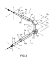
- the figure 3 represents a first embodiment of a pumping head according to the invention. It comprises a first and a second substantially identical amplifying medium 1, 1 'of the type of those represented on FIG. figure 1 , each formed of a block with an inlet face (10, 10 '), an outlet face (11, 11') and four lateral faces, of which two main faces facing substantially parallel, respectively 121 , 122 and 121 ', 122'.
- the block forming the amplifying medium is substantially parallelepipedal, with the parallel or substantially trapezoidal input and output faces with the non-parallel input and output faces, as on FIG. figure 3 .
- the amplifying media 1, 1 ' are for example formed with a YAG (Yttrium garnet aluminum) type crystal, pumped by rare earth ions, such as for example Erbium, Holmium, Neodymium or Thulium.
- rare earth ions such as for example Erbium, Holmium, Neodymium or Thulium.
- Other materials can of course be used to produce amplifying media, such as phosphate or silicate glasses, and generally any laser medium having a high refractive index.
- the pumping head further comprises first and second pumping means amplifying media (not shown on the figure 3 ), according to one of the main faces of each of the media, called the main pumping face (respectively 121 and 121 ').
- the pumping means are intended to emit a pumping flow F P making it possible to form in each amplifying medium a pumping zone (no represented on the figure 3 but similar to the pumping zone 3 of Figures 1, 2A and 2B ), extending from the main pumping face to the opposite face, and in which an optical beam to be amplified, incident on the input face, is intended to propagate.
- the refractive index of the amplifying medium is generally high relative to that of the materials in contact with the main faces, so that a beam incident on the input side of an amplifying medium with an angle of incidence given zig-zag propagates to the exit face, by total reflections on the main faces.
- This zigzag propagation makes it possible to compensate for the distortion effects due to the thermal gradient in the direction parallel to the direction of the pumping flow F P.
- the pumping means comprise laser diodes or stacks of laser diodes substantially aligned along the main pumping surface, between the input and output faces of the amplifying medium.
- Other means of pumping can be used, such as flashlights, arches, or filament lamps.
- the pumping head may comprise cooling devices for the amplifying media (not shown in FIG. figure 3 ), in particular for cooling the face vis-à-vis the main face of pumping.
- each cooling device of each of the amplifying media comprises a cooling block of the face opposite the main pumping surface, of the type of the cooling block 5 shown in FIG. figure 1 , with, advantageously, an intermediate layer of index given between the face to be cooled and the cooling block to ensure total reflection on said face during zig-zag propagation of the beam to be amplified.
- each cooling device then comprising a cooling block for each of the main faces.
- the amplifying media 1, 1 ' are arranged relative to one another so that their main faces are located in parallel planes, the pumping zones being non-coplanar.
- the optical beam to be amplified 4 is identified by its different parts relative to the positions of the amplifying media.
- the portion of the incident beam on the first amplifying medium 41, the portion of the emerging beam of the first amplifying medium and incident on the second amplifying medium, and 42 the portion of the emerging beam of the second amplifying medium are noted.
- the pumping head comprises an optical reflection device 6 with at least two plane mirrors 61, 62 arranged in such a way that the beam 41 emerges from the first amplifying medium undergoes a rotation of 90 ° about its axis of propagation before to enter the pumping zone of the second amplifying medium.
- the optical device 6 of reflection of the pumping head according to the invention makes it possible to compensate without introducing additional optical element, and in particular of element acting on the phase, the phase distortion of the optical beam introduced by the thermal gradients of the first amplifying medium, by simple propagation in the second amplifying medium, substantially identical to the first.
- the axis z 1 of propagation of the emergent beam 41 of the first amplifier is in a given first plane ( ⁇ 1 ), and the two plane mirrors 61, 62 are arranged in such a way that the axis of propagation Z 2 of the beam after reflection on the two mirrors is in a second plane ( ⁇ 2 ) parallel to the first, the z axis 2 being perpendicular to the direction of the propagation axis z 1 before reflection.
- the two amplifying media 1, 1 ' are arranged in two distinct parallel planes, so that the pumping zones are substantially perpendicular to each other.
- the beam 41 coming from the first amplifying medium propagates in the plane ⁇ 1 , is reflected on the mirror 61 in a vertical plane, then returns in a plane ⁇ 2 parallel to the initial plane after reflection on the plane mirror 62.
- the change planes makes it possible to turn the beam 41 by 90 ° without introducing depolarization of the incident beam when the latter is polarized linearly.
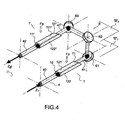
- the figure 4 represents a second variant of a pumping head according to the invention, substantially similar to the pumping head shown in FIG. figure 3 but in which the optical reflection device comprises a third reflecting mirror 63 for reducing the axis of propagation z 3 of the beam after reflection on the three mirrors in a direction substantially parallel to the direction of the propagation axis z 1 before reflection, but not aligned, the two amplifying media 1, 1 'then being arranged in two distinct parallel planes with the pumping zones substantially parallel to each other. 'other.
- the change of planes made thanks to the reflection mirrors 61 and 62 makes it possible to rotate the beam 41 by 90 °.
- This variant has the additional advantage, thanks to the third mirror 63, of reducing the bulk of the pumping head, in particular with respect to the devices of the prior art in which the amplifying media were necessarily arranged along collinear axes.
- the invention further relates to a laser amplifier with one or more pump heads as described above, and for example represented on the figures 3 or 4 .
- An incident beam in the amplifier is then intended to be amplified by each of the amplifying media of the pump head or heads.
- the amplification is made by single passage in each of the amplifying media.
- a multiple passage of the beam to be amplified is provided in the pumping zone of one or more of the amplifying media.
- the invention also relates to a laser oscillator comprising an oscillating cavity closed by two mirrors with in the cavity, one or more pump heads as described above.
- the oscillator may further comprise a Q-switch trigger.
Landscapes
- Physics & Mathematics (AREA)
- Electromagnetism (AREA)
- Engineering & Computer Science (AREA)
- Plasma & Fusion (AREA)
- Optics & Photonics (AREA)
- Chemical & Material Sciences (AREA)
- Crystallography & Structural Chemistry (AREA)
- Lasers (AREA)
Claims (14)
- Pumpkopf für optischen Verstärker mit Lasereffekt, der enthält:- ein erstes und ein zweites verstärkendes Medium (1, 1'), die im Wesentlichen gleich sind und jeweils aus einem Block mit einer Eintrittsfläche (10, 10'), einer Austrittsfläche (11, 11') und vier Seitenflächen (121, 122, 121', 122'), wovon zwei gegenüberliegende Hauptflächen im Wesentlichen parallel sind, gebildet sind,- erste und zweite Pumpmittel (2) für die verstärkenden Medien längs einer der Hauptflächen jedes der Medien, die Pumphauptfläche (121, 121') genannt wird, wobei die Pumpmittel dazu bestimmt sind, in jedem der verstärkenden Medien eine Pumpzone (3) zu bilden, die einen Streifen bildet, der sich von der Pumphauptfläche bis zu der gegenüberliegenden Fläche erstreckt, in der sich ein zu verstärkendes Lichtstrahlenbündel (4), das auf die Eintrittsfläche auftrifft, durch Totalreflexion an den Hauptflächen zickzackförmig bis zu der Austrittsflächefläche ausbreiten soll,wobei die verstärkenden Medien (1, 1') relativ zueinander so angeordnet sind, dass sich ihre Hauptflächen in verschiedenen parallelen Ebenen befinden, wobei der Pumpkopf dadurch gekennzeichnet ist, dass die Pumpzonen nicht koplanar sind und dass er eine optische Reflexionsvorrichtung (6) mit zwei ebenen Spiegeln (61, 62) enthält, die in der Weise angeordnet sind, dass das aus dem ersten verstärkenden Medium längs einer gegebenen Ausbreitungsachse (z1) austretende Strahlenbündel (41) mittels der Spiegel eine Drehung um 90° um die Ausbreitungsachse erfährt, bevor es in die Pumpzone des zweiten verstärkenden Mediums eindringt, und dass die Richtung der Ausbreitungsachse (z2) des Strahlenbündels nach der Reflexion an den zwei Spiegeln zu der Richtung der Ausbreitungsachse (z1) des Strahlenbündels vor der Reflexion senkrecht ist.
- Pumpkopf nach Anspruch 1, bei dem die zwei verstärkenden Medien in zwei verschiedenen parallelen Ebenen angeordnet sind, derart, dass die Pumpzonen im Wesentlichen zueinander parallel sind.
- Pumpkopf für optischen Verstärker mit Lasereffekt, der enthält:- ein erstes und ein zweites verstärkendes Medium (1, 1'), die im Wesentlichen gleich sind und jeweils aus einem Block mit einer Eintrittsfläche (10, 10'), einer Austrittsfläche (11, 11') und vier Seitenflächen (121, 122, 121', 122'), wovon zwei gegenüberliegende Hauptflächen im Wesentlichen parallel sind, gebildet sind,- erste und zweite Pumpmittel (2) für die verstärkenden Medien längs einer der Hauptflächen jedes der Medien, die Pumphauptfläche (121, 121') genannt wird, wobei die Pumpmittel dazu bestimmt sind, in jedem der verstärkenden Medien eine Pumpzone (3) zu bilden, die einen Streifen bildet, der sich von der Pumphauptfläche bis zu der gegenüberliegenden Fläche erstreckt, in der sich das zu verstärkende optische Strahlenbündel (4), das auf die Eintrittsfläche auftritt, durch Totalreflexion an den Hauptflächen zickzackförmig bis zu der Austrittsfläche ausbreiten soll,wobei die verstärkenden Medien (1, 1') relativ zueinander in der Weise angeordnet sind, dass sich ihre Hauptflächen in verschiedenen parallelen Ebenen befinden, wobei der Pumpkopf dadurch gekennzeichnet ist, dass die Pumpzonen nicht koplanar sind,
und dass er eine optische Reflexionsvorrichtung (6) mit drei ebenen Spiegeln (61, 62, 63) enthält, die in der Weise angeordnet sind, dass das aus dem ersten Verstärker (1) austretende Strahlenbündel (41), das in einer gegebenen ersten Ebene (Π1) enthalten ist, nach einer Reflexion an zwei ersten Spiegeln (61, 62) und nach einer Reflexion an dem dritten Spiegel (63) in einer zweiten Ebene (Π2), die zu der ersten parallel ist, enthalten ist, wobei das Strahlenbündel (41), das aus dem ersten verstärkenden Medium längs einer gegebenen Ausbreitungsachse (z1) austritt, mittels der zwei ersten Spiegel (61, 62) eine Drehung um 90° um die Ausbreitungsachse erfährt, bevor es durch den dritten Spiegel (63) reflektiert wird, und dass die Richtung der Ausbreitungsachse (z2) des Strahlenbündels nach einer Reflexion an den zwei ersten Spiegeln (61, 62) zur Richtung der Ausbreitungsachse (z1) des Strahlenbündels vor der Reflexion senkrecht ist und die Ausbreitungsachse (z3) des Strahlenbündels nach der Reflexion an dem dritten Spiegel (63) eine Richtung hat, die zu der Richtung der Ausbreitungsachse (z1) vor der Reflexion im Wesentlichen parallel ist,
wobei die zwei verstärkenden Medien in zwei verschiedenen parallelen Ebenen angeordnet sind, wobei die Pumpzonen im Wesentlichen parallel zueinander sind. - Pumpkopf nach einem der vorhergehenden Ansprüche, bei dem die ersten und die zweiten Pumpmittel Laserdioden oder Laserdioden-Anordnungen enthalten, die im Wesentlichen längs der Pumphauptfläche zwischen der Eintrittsfläche und der Austrittsfläche des verstärkenden Mediums ausgerichtet sind.
- Pumpkopf nach einem der vorhergehenden Ansprüche, der außerdem eine erste und eine zweite Kühlungsvorrichtung für die verstärkenden Medien (5), insbesondere für die Kühlung der Fläche gegenüber der Pumphauptfläche, enthält.
- Pumpkopf nach Anspruch 5, bei dem jede Kühlungsvorrichtung einen Kühlungsblock für die Fläche gegenüber der Pumphauptfläche enthält, wobei eine Zwischenschicht mit gegebenem Brechungsindex zwischen dieser Fläche und dem Kühlungsblock vorhanden ist, um die Totalreflexion an dieser Fläche bei der zickzackförmigen Ausbreitung des zu verstärkenden Strahlenbündels zu gewährleisten.
- Pumpkopf nach einem der vorhergehenden Ansprüche, der außerdem für jedes der verstärkenden Medien Pumpmittel für die Fläche gegenüber der Pumphauptfläche enthält, wobei jede Kühlungsvorrichtung einen Kühlungsblock für jede der Hauptflächen enthält.
- Pumpkopf nach einem der vorhergehenden Ansprüche,
wobei der Block, der das verstärkende Medium bildet, im Wesentlichen die Form eines Parallelepipeds hat, wobei die Eintrittsfläche und die Austrittsfläche parallel sind, oder im Wesentlichen die Form eines Trapezes hat,
wobei die Eintrittsfläche und die Austrittsfläche nicht parallel sind. - Pumpkopf nach einem der vorhergehenden Ansprüche,
wobei das verstärkende Medium aus einem Kristall des YAG-Typs, der durch Seltenerd-Ionen gepumpt wird, gebildet ist. - Pumpkopf nach Anspruch 9, wobei die Seltenerd-Ionen Erbium, Holmium, Neodym oder Thulium sind.
- Laserverstärker, der einen oder mehrere Pumpköpfe nach einem der vorhergehenden Ansprüche enthält, wobei ein auf den Verstärker auftreffendes Strahlenbündel durch jedes der verstärkenden Medien des oder der Pumpköpfe verstärkt werden soll.
- Laserverstärker nach Anspruch 11, wobei die Verstärkung in einem oder in mehreren der verstärkenden Medien durch einen mehrfachen Durchgang des zu verstärkenden Strahlenbündels durch die Pumpzone des Mediums erfolgt.
- Laseroszillator, der einen Resonanzhohlraum, der durch zwei Spiegel verschlossen ist, und in dem Hohlraum einen oder mehrere Pumpköpfe nach einem der Ansprüche 1 bis 10 enthält.
- Laseroszillator nach Anspruch 13, der außerdem einen Güteschalter des Typs Q-Switch enthält.
Applications Claiming Priority (2)
| Application Number | Priority Date | Filing Date | Title |
|---|---|---|---|
| FR0401284A FR2866161B1 (fr) | 2004-02-10 | 2004-02-10 | Tete de pompage pour amplificateur optique a effet laser |
| FR0401284 | 2004-02-10 |
Publications (3)
| Publication Number | Publication Date |
|---|---|
| EP1564852A1 EP1564852A1 (de) | 2005-08-17 |
| EP1564852B1 EP1564852B1 (de) | 2008-08-06 |
| EP1564852B9 true EP1564852B9 (de) | 2009-03-11 |
Family
ID=34685001
Family Applications (1)
| Application Number | Title | Priority Date | Filing Date |
|---|---|---|---|
| EP20050100894 Ceased EP1564852B9 (de) | 2004-02-10 | 2005-02-09 | Pumpvorrichtung für einen optischen Laserverstärker |
Country Status (3)
| Country | Link |
|---|---|
| EP (1) | EP1564852B9 (de) |
| DE (1) | DE602005008653D1 (de) |
| FR (1) | FR2866161B1 (de) |
Families Citing this family (1)
| Publication number | Priority date | Publication date | Assignee | Title |
|---|---|---|---|---|
| FR3051511B1 (fr) * | 2016-05-18 | 2020-10-02 | Renault Sas | Bougie laser pour moteur a combustion |
Family Cites Families (3)
| Publication number | Priority date | Publication date | Assignee | Title |
|---|---|---|---|---|
| EP0256047A1 (de) * | 1986-01-30 | 1988-02-24 | Advanced Lasers Ltd. | Kompaktes schicht-laser-oszillator-verstärkersystem |
| JPH06268292A (ja) * | 1993-03-10 | 1994-09-22 | Univ Osaka | 固体レーザ発振装置 |
| US6178040B1 (en) * | 1998-06-25 | 2001-01-23 | Trw Inc. | Laser with two orthogonal zig-zag slab gain media for optical phase distortion compensation |
-
2004
- 2004-02-10 FR FR0401284A patent/FR2866161B1/fr not_active Expired - Fee Related
-
2005
- 2005-02-09 EP EP20050100894 patent/EP1564852B9/de not_active Ceased
- 2005-02-09 DE DE200560008653 patent/DE602005008653D1/de not_active Expired - Lifetime
Also Published As
| Publication number | Publication date |
|---|---|
| EP1564852B1 (de) | 2008-08-06 |
| EP1564852A1 (de) | 2005-08-17 |
| DE602005008653D1 (de) | 2008-09-18 |
| FR2866161B1 (fr) | 2006-04-21 |
| FR2866161A1 (fr) | 2005-08-12 |
Similar Documents
| Publication | Publication Date | Title |
|---|---|---|
| EP0296512B1 (de) | Laser mit verbessertem Kühlungssystem | |
| EP1480299B1 (de) | Diodengepumpter Festkörper-Scheibenlaser und Verfahren zur Erzeugung einer gleichförmigen Verstärkung | |
| AU778304B2 (en) | Side pumped Q-switched microlaser and associated fabrication method | |
| US6667999B2 (en) | Cooling of high power laser systems | |
| EP0390662B1 (de) | Hochleistungs-Laser mit Steuerung der Richtung der Ausgangsstrahlung | |
| FR2665307A1 (fr) | Systeme laser adapte. | |
| EP0847115B1 (de) | Lichtverstärkervorrichtung mit zwei einfallenden Bündeln | |
| US4987376A (en) | Frequency shifted laser transmitter | |
| EP1564852B1 (de) | Pumpvorrichtung für einen optischen Laserverstärker | |
| EP1166402A1 (de) | Vorrichtung zum optischen pumpen eines lasers, die einen zylindrischen reflektor mit polygonalem quernschnitt enthält | |
| EP3379661B1 (de) | Laserverstärkungsvorrichtung mit aktiver kontrolle der qualität des laserstrahls und endschienen | |
| JP4688024B2 (ja) | ファラデー回転子の製造方法及び該回転子が組込まれた光アイソレータ | |
| EP4264752A1 (de) | Vorrichtung zur verstärkung eines laserstrahls | |
| EP4128452B1 (de) | T-förmige laserpumpvorrichtung | |
| WO2003050925A2 (fr) | Resonateur optique en anneau sans surface, appareil de communication et/ou de projections video correspondant | |
| EP0767519A1 (de) | Vorrichtung zur optischen Verstärkung | |
| CA3202319A1 (fr) | Dispositif d'amplification d'un faisceau laser | |
| EP3701602A1 (de) | Festkörperlaserquelle | |
| FR2756110A1 (fr) | Oscillateur optique a agilite de pointage et source laser utilisant cet oscillateur optique | |
| FR2861223A1 (fr) | Dispositif de pompage optique par diodes laser et procede de pompage optique associe. | |
| FR2704096A1 (fr) | Procédé de réalisation d'une cellule acousto-optique pour laser déclenché, cellule obtenue, procédé de réalisation collective de microlasers déclenchés et microlasers obtenus. | |
| FR3006510A1 (fr) | Systeme d'amplification laser a disque epais et applications | |
| FR2785099A1 (fr) | Laser a l'etat solide, notamment microlaser, capable d'emettre des impulsions longues | |
| WO2020094416A1 (fr) | Tete amplificatrice laser de haute puissance | |
| FR2671641A1 (fr) | Miroir a rendement eleve pour la technique des lasers. |
Legal Events
| Date | Code | Title | Description |
|---|---|---|---|
| PUAI | Public reference made under article 153(3) epc to a published international application that has entered the european phase |
Free format text: ORIGINAL CODE: 0009012 |
|
| AK | Designated contracting states |
Kind code of ref document: A1 Designated state(s): AT BE BG CH CY CZ DE DK EE ES FI FR GB GR HU IE IS IT LI LT LU MC NL PL PT RO SE SI SK TR |
|
| AX | Request for extension of the european patent |
Extension state: AL BA HR LV MK YU |
|
| 17P | Request for examination filed |
Effective date: 20060127 |
|
| AKX | Designation fees paid |
Designated state(s): DE FR IT NL |
|
| 17Q | First examination report despatched |
Effective date: 20060517 |
|
| GRAP | Despatch of communication of intention to grant a patent |
Free format text: ORIGINAL CODE: EPIDOSNIGR1 |
|
| GRAS | Grant fee paid |
Free format text: ORIGINAL CODE: EPIDOSNIGR3 |
|
| GRAA | (expected) grant |
Free format text: ORIGINAL CODE: 0009210 |
|
| AK | Designated contracting states |
Kind code of ref document: B1 Designated state(s): DE FR IT NL |
|
| REF | Corresponds to: |
Ref document number: 602005008653 Country of ref document: DE Date of ref document: 20080918 Kind code of ref document: P |
|
| PLBE | No opposition filed within time limit |
Free format text: ORIGINAL CODE: 0009261 |
|
| STAA | Information on the status of an ep patent application or granted ep patent |
Free format text: STATUS: NO OPPOSITION FILED WITHIN TIME LIMIT |
|
| 26N | No opposition filed |
Effective date: 20090507 |
|
| REG | Reference to a national code |
Ref country code: FR Ref legal event code: PLFP Year of fee payment: 12 |
|
| REG | Reference to a national code |
Ref country code: FR Ref legal event code: PLFP Year of fee payment: 13 |
|
| REG | Reference to a national code |
Ref country code: FR Ref legal event code: PLFP Year of fee payment: 14 |
|
| PGFP | Annual fee paid to national office [announced via postgrant information from national office to epo] |
Ref country code: DE Payment date: 20200129 Year of fee payment: 16 Ref country code: NL Payment date: 20200212 Year of fee payment: 16 Ref country code: IT Payment date: 20200128 Year of fee payment: 16 |
|
| PGFP | Annual fee paid to national office [announced via postgrant information from national office to epo] |
Ref country code: FR Payment date: 20200127 Year of fee payment: 16 |
|
| REG | Reference to a national code |
Ref country code: DE Ref legal event code: R119 Ref document number: 602005008653 Country of ref document: DE |
|
| REG | Reference to a national code |
Ref country code: NL Ref legal event code: MM Effective date: 20210301 |
|
| PG25 | Lapsed in a contracting state [announced via postgrant information from national office to epo] |
Ref country code: NL Free format text: LAPSE BECAUSE OF NON-PAYMENT OF DUE FEES Effective date: 20210301 |
|
| PG25 | Lapsed in a contracting state [announced via postgrant information from national office to epo] |
Ref country code: FR Free format text: LAPSE BECAUSE OF NON-PAYMENT OF DUE FEES Effective date: 20210228 Ref country code: DE Free format text: LAPSE BECAUSE OF NON-PAYMENT OF DUE FEES Effective date: 20210901 |
|
| PG25 | Lapsed in a contracting state [announced via postgrant information from national office to epo] |
Ref country code: IT Free format text: LAPSE BECAUSE OF NON-PAYMENT OF DUE FEES Effective date: 20210209 |
|
| P01 | Opt-out of the competence of the unified patent court (upc) registered |
Effective date: 20230529 |