EP1564696A2 - Automatic beverage vending machine. - Google Patents
Automatic beverage vending machine. Download PDFInfo
- Publication number
- EP1564696A2 EP1564696A2 EP05250816A EP05250816A EP1564696A2 EP 1564696 A2 EP1564696 A2 EP 1564696A2 EP 05250816 A EP05250816 A EP 05250816A EP 05250816 A EP05250816 A EP 05250816A EP 1564696 A2 EP1564696 A2 EP 1564696A2
- Authority
- EP
- European Patent Office
- Prior art keywords
- gate
- vending machine
- cup
- article outlet
- carrying mechanism
- Prior art date
- Legal status (The legal status is an assumption and is not a legal conclusion. Google has not performed a legal analysis and makes no representation as to the accuracy of the status listed.)
- Withdrawn
Links
Images




Classifications
-
- G—PHYSICS
- G07—CHECKING-DEVICES
- G07F—COIN-FREED OR LIKE APPARATUS
- G07F13/00—Coin-freed apparatus for controlling dispensing or fluids, semiliquids or granular material from reservoirs
- G07F13/06—Coin-freed apparatus for controlling dispensing or fluids, semiliquids or granular material from reservoirs with selective dispensing of different fluids or materials or mixtures thereof
- G07F13/065—Coin-freed apparatus for controlling dispensing or fluids, semiliquids or granular material from reservoirs with selective dispensing of different fluids or materials or mixtures thereof for drink preparation
-
- G—PHYSICS
- G07—CHECKING-DEVICES
- G07F—COIN-FREED OR LIKE APPARATUS
- G07F13/00—Coin-freed apparatus for controlling dispensing or fluids, semiliquids or granular material from reservoirs
- G07F13/10—Coin-freed apparatus for controlling dispensing or fluids, semiliquids or granular material from reservoirs with associated dispensing of containers, e.g. cups or other articles
Definitions
- the present invention relates to an automatic beverage vending machine which sells coffee, black tea or some other refreshment poured into a cup each time.
- a known automatic beverage vending machine of this kind is provided with a cup feeding device for feeding cups; a material feeding device for feeding the material, such as ground coffee, into each cup; a beverage brewer for brewing a beverage by blending the material with cold or hot water; a carrying mechanism for carrying cups, and a gate for opening and closing an article outlet.
- cups are successively moved one by one to the material feeding device and the beverage brewer, the beverage is brewed, and cups filled with the beverage are carried to the article outlet.
- the buyer is to pick up a filled cup from the article outlet of this automatic beverage vending machine, he has to open the gate with one hand and take the cup out of the article outlet with the other.
- a vending machine whose gate is automatically opened by a driving motor when a filled cup has been carried to the inside of the article outlet has been developed.
- An object of the present invention is to provide an automatic beverage vending machine permitting automatic opening of the gate of the article outlet with a simple structure.
- an automatic beverage vending machine is provided with a carrying mechanism for carrying cups filled with beverage to an article outlet, a gate for opening and closing the article outlet, and a gate releasing mechanism for moving, when the carrying mechanism carries a cup in a prescribed direction toward the article outlet, the gate in the opening direction by coming into contact with a prescribed member on the carrying mechanism side.
- the gate when the carrying mechanism carries a cup toward the article outlet, the gate to be opened by the gate releasing mechanism as a prescribed member on the carrying mechanism side comes into contact, the gate is automatically opened without having to use a power source, such as a dedicated motor for use in opening the gate.
- a power source such as a dedicated motor for use in opening the gate.
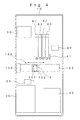
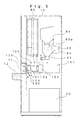
- This automatic beverage vending machine comprises an automatic vending machine body 10, a water feed tank 20 for storing drinking water to be used for preparing the beverage, a refrigerating unit 30 for preparing cold water, a boiler 40 for preparing hot water, an ice maker 50 for making ice, first through fourth material containers 61, 62, 63 and 64 for storing a plurality of kinds of powdered raw material, a fifth material container 65 for storing coffee beans as a rawmaterial, a beverage extractor 70 for extracting beverage coffee, a drain water container 80 for storing unnecessary drain liquid, a cup carrying mechanism 90 for carrying cups A, a carrying mechanism 100 for successively carrying to a prescribed position in the automatic vending machine body 10 the cups A discharged from the cup carrying mechanism 90 and carrying Cups A filled with beverage to the article outlet, a gate 110 for opening and closing the article outlet, a gate releasing mechanism 120 for opening the gate 110 by bringing into contact a member fitted to the carrying mechanism 100, and a locking mechanism 130 for locking the gate 110.
- the automatic vending machine body 10 is provided with an article outlet 11 disposed substantially at the center of the front face of the body 10, an article mounting base 12 consisting of a lower forward-protruding part of the article outlet 11, an image display unit 13 disposed above the article outlet 11 to display information on the articles sold and the handling of the machine to buy an article, a plurality of selector switches 14 arranged on the right and left sides of the image display unit 13, and a price display window 15 arranged above the image display unit 13.
- the water feed tank 20 is connected to the refrigerating unit 30, the boiler 40 and the ice maker 50 via a water feed pump 21, and the water feed pump 21 feeds the drinking water stored within the tank 20 to the refrigerating unit 30, the boiler 40 and the ice maker 50.
- This water feed tank 20 is installed in a lower part within the automatic vending machine body 10, and can either be directly refilled with water from outside or replaced with another water feed tank 20 filled with water.
- the refrigerating unit 30 consists of cold water piping and a cold water tank (neither shown), and water within the cold water piping fed from the water feed tank 20 via the water feed pump 21 is refrigerated in the cold water tank.
- the boiler 40 generates hot water of around 90°C with an internal heater not shown. It consists of a known small-size instant water boiler, which heats water fed from the water feed tank 20 via the water feed pump 21.
- the boiler 40 is connected to a hot water nozzle 41 for directly feeding hot water to the beverage extractor 70 and into cups A.
- the ice maker 50 consisting of an ice making section and an ice stocker section (neither shown), generates ice from water fed to the ice making section from the water feed tank 20 via the water feed pump 21, and stocks the generated pieces of ice in the ice stocker section.
- the first through fourth material containers 61, 62, 63 and 64 respectively contain black tea, cocoa, cream and sugar, and a prescribed quantity of each material is delivered from a material chute.
- the fifth material container 65 having a mill 65a for grinding coffee beans, delivers a prescribed quantity of ground coffee as a material to the beverage extractor 70.
- the beverage extractor 70 has a known structure for extracting beverage coffee from the material (ground beans) by using hot water fed from the boiler 40, and the extracted coffee is poured into cups A.
- the drain water container 80 installed underneath the automatic vending machine body 10, stores unnecessary liquid discharged from the drain outlet of the boiler 40 and the article outlet 11.
- the cup carrying mechanism 90 having a known structure for accommodating cups A intended for the vending of beverage, drops the cups A one by one toward the carrying mechanism 100.
- the carrying mechanism 100 comprises a cup holder 101 for holding cups A, a first carrying mechanism 102 for moving the cup holder 101 up and down, a second carrying mechanism 103 for moving the first carrying mechanism 102 in the widthwise direction, and a third carrying mechanism 104 for moving the second carrying mechanism 103 in the back and forth direction.
- the cup holder 101 consists of an arc-shaped member.
- the cup holder 101 holds cups A by engaging the upper edge of the side of each cup A with the inner face of the cup holder 101.
- the first through third carrying mechanisms 102, 103 and 104 move the cup holder 101 linked to the first carrying mechanism 102 in the back-and-forth, widthwise and up-and-down directions by driving with motors (not shown) the first through third carrying mechanism 102, 103 and 104 by way of a known cam mechanism, belt mechanism or the like (not shown) disposed in each of the carrying mechanism bodies 102a, 103a and 104a.
- the gate 110 opens and closes the article outlet 11 with a pair of door members 111 arranged abreast.
- each of the door members 111 is moved in one or the other widthwise direction to open the article outlet 11.
- An engaging portion 111c is disposed at the lower end of the front face of each door member 111, and by engaging both ends of a coil spring 111d with the engaging portion 111c, the gate 110 is urged in the closing direction.
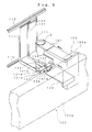
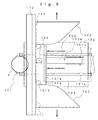
- the gate releasing mechanism 120 comprises a gate releasing unit 121 as a gate releasing member for opening the gate 110, a contact portion 122 disposed on each of the door members 111 and coming into contact with both ends, in the widthwise direction, of the gate releasing unit 121, and an extruding plate 123 as an extruding member for moving the gate releasing unit 121 forward.
- the gate releasing unit 121 is disposed in a lower part within the article outlet 11, and its gate releasing unit body 121a is supported toward the automatic vending machine body 10 to be movable in the back-and-forth direction.
- the gate releasing unit body 121a is formed by bending downward the front and rear ends of a planar member extending in the widthwise direction, and a pair of holes 121b, arranged abreast, are formed in its front and rear faces.
- the gate releasing unit body 121a By inserting into the back-and-forth sequences of the holes 121b a pair of guide shafts 121c fixed to a fixed plate 10a positioned downward from the article outlet 11 and extending in the back-and-forth direction, the gate releasing unit body 121a is supported by the automatic vending machine body 10 to be movable in the back-and-forth direction.
- a pair of rollers 121d On the front side of the two ends, in the widthwise direction, of the gate releasing unit body 121a, there are rotatably disposed a pair of rollers 121d, arranged abreast, to be in contact with the contact portions 122, and in the upper part of the rear side, there is disposed an extruding portion 121e, with which the extruding plate 123 comes into contact, extending in the widthwise direction.
- Each of the contact portions 122 is formed in a curvilinear shape extending in the lower part of the rear side of each door member 111 backward from the inside of the door member 111 in the widthwise direction and also bending outward in the widthwise direction, so that they face the respectively matching door members 111 in the widthwise direction.
- Each of the contact portions 122 comes into contact with one or another of the rollers 121d of the gate releasing unit 121. By moving the gate releasing unit 121 forward, the door members 111 are moved outward in one or the other widthwise direction.
- the extruding plate 123 disposed underneath the cup holder 101, is fixed to the first carrying mechanism body 102a at a height of coming into contact with the extruding portion 121e of the gate releasing unit 121.
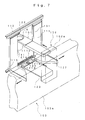
- the locking mechanism 130 comprises a lock shaft 131 as a lock member provided on one of the door members 111, a shaft receptacle 132 as an engaging portion which is provided on the other door member 111 and into which the upper end of the lock shaft 131 is inserted, a movable plate 133 as a movable member coming into contact with the lower end of the lock shaft 131, and an unlocking roller 134 as an unlocking member moving over the movable plate 133.
- the lock shaft 131 disposed to extend in the vertical direction inside the rear side of one of the door members 111 in the widthwise direction, is movable in the up-and-down direction within a prescribed range relative to the door members 111.
- the shaft receptacle 132 is disposed to extend from the upper end of the rear side of the other door member 111 toward the mating door member 111, and a shaft receiving hole 132a, into which the upper end of the lock shaft 131 is to be inserted, is formed in the lower face of the shaft receptacle 132.
- the gate 110 is locked in a state of closing the article outlet 11 by moving the lock shaft 131 upward and inserting the upper end of the lock shaft 131 into the shaft receiving hole 132a.
- the movable plate 133 consists of a member extending in the back-and-forth direction, with its front end positioned underneath the lock shaft 131 and its rear end supported to be rotatable in the up-and-down direction by the fixed plate 10a of the automatic vending machine body 10.
- a hole 133a for inserting a bolt is formed toward the front end of substantially the central part of the movable plate 133, and a bolt 133b is inserted into the hole 133a from above to be screwed onto the fixed plate 10a underneath.
- the bolt 133b is so screwed onto the fixed plate 10a as to leave a gap which allows the movable plate 133 to turn in the up-and-down direction within a prescribed range, and a coil spring 133c intervenes between the movable plate 133 and the fixed plate 10a.
- the unlocking roller 134 arranged in substantially the central part of the gate releasing unit body 121a in the widthwise direction to be turnable in the back-and-forth direction, moves over the upper face of the movable plate 133 in the back-and-forth direction along with the movement of the gate releasing unit 121.
- the cup holder 101 of the carrying mechanism 100 will move toward underneath the delivery outlet of the cup carrying mechanism 90, and a cup A is delivered by the cup carrying mechanism 90.
- the delivered cup A in a state of being held by the cup holder 101, moves within the automatic vending machine body 10, and a beverage of the buyer's choice in poured into it.
- tea is selected with one of the selector switches 14, after moving the cup A underneath the first material container 61 and feeding the cup A with the material from the first material container 61, the cup A is moved to underneath the hot water nozzle 41, where hot water is fed from the boiler 40 into the cup A to prepare the beverage.
- the cup A is moved to underneath the beverage extractor 70 and, after beverage coffee is extracted by the beverage extractor 70 into the cup A with hot water fed from the boiler 40, the cup A is moved to underneath the third material container 63, the appropriate material is fed from the third material container 63 into the cup A, the cup A is further moved to underneath the fourth material container 64, and coffee with cream and sugar is prepared as the materials are fed from the fourth material container 64 into the cup A.
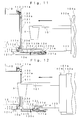
- the carrying mechanism 100 moves the cup A from behind to before the article outlet 11 as shown in Fig. 11 and, when the cup A arrives at the rear side of the gate 110, the extruding plate 123 fixed to the carrying mechanism body 102a comes into contact with the extruding portion 121e of the gate releasing unit 121.
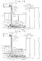
- the cup A is carried out of the automatic vending machine body 10 through the opened article outlet 11 as shown in Fig. 13, and by moving downward the cup A as shown in Fig. 14, the cup A is placed on the article mounting base 12.
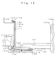
- the cup holder 101 is moved after this to underneath the cup A and backward, the cup holder 101 recedes leaving the cup A on the article mounting base 12 as shown in Fig. 15, and the cup holder 101 moves to a standby position in the automatic vending machined body 10 to end the operation.
- the door members 111 of the gate 110 are moved by the urge of the coil springs 111d in the direction of closing the article outlet 11.
- the gate releasing unit 121 is moved backward by the upward urge of the front end of the movable plate 133, and the lock shaft 131 is moved upward by the lock piece 133d to lock the gate 110 in a closed state.
- the extruding plate 123 fitted to the first carrying mechanism body 102a opens the gate 110. Therefore, the gate 110 can be opened automatically without having to use a power source, such as a dedicated motor, making it possible to reduce the manufacturing cost by dispensing with expensive equipment, such as a dedicated motor and facilitating the pickup of delivered cups A by the buyers.
- a power source such as a dedicated motor
- the gate releasing mechanism 120 is configured of the gate releasing unit 121 disposed to be movable in the back-and-forth direction within the article outlet 11, the contact portions 122 provided on the door members 111 and the extruding plate 123 to move the gate releasing unit 121 by the forward carrying action of the carrying mechanism 100, and the door members 111 are moved toward their respective end sides in the widthwise direction by bringing the rollers 121d of the gate releasing unit 121 into contact with the contact portions 122. Accordingly, the gate 110 is enabled to be reliably opened in this simple configuration, a feature contributing to reductions in the number of components and manufacturing cost.
- the gate 110 is locked when it is closed, the article outlet 11 will not be accidentally opened except when a cup A is to be delivered, preventing a human hand or any foreign matter from being unnecessarily inserted into the article outlet 11.
- the configuration to cause the gate 110 to be unlocked by the movement of the gate releasing unit 121 enables the gate 110 to be locked in a simple configuration, requiring no expensive equipment such as a sensor or a solenoid.
- the gate releasing unit 121 is moved in response to the carriage of a cup A, and the article outlet 11 is opened by bringing the rollers 121d of the gate releasing unit 121 into contact with the contact portions 122 disposed on the door members 111
- the gate 110 is configured of the pair of door members 111 arranged abreast, whose upper and lower ends are supported to be movable in the widthwise direction, and the article outlet 11 is opened by having the door members 111 moved toward the two sides in the widthwise direction by the gate releasing mechanism 120, but the gate 110 can as well be composed of a single door member whose upper and lower ends are supported to be movable in the widthwise direction to open the article outlet 11 by having the gate releasing mechanism 120 move the door member in the widthwise direction.
- the gate 110 may be configured of at least one door member whose one end in the widthwise direction, or one end in the up-and-down direction, of the article outlet 11, with the article outlet 11 being opened by having the gate releasing mechanism 120 turn the door member.
- the extruding plate 123 disposed on the carrying mechanism 100 for delivering the cups A the article outlet 11 is enabled to move the gate releasing unit 121 in the direction of opening the door, but the gate releasing unit 121 may as well be moved in the direction of opening the door by a member disposed on the carrying mechanism 100 for delivering a cup A to the article outlet 11 by moving the cup A in either the up-and-down direction or in the widthwise direction.
Landscapes
- Physics & Mathematics (AREA)
- General Physics & Mathematics (AREA)
- Beverage Vending Machines With Cups, And Gas Or Electricity Vending Machines (AREA)
- Control Of Vending Devices And Auxiliary Devices For Vending Devices (AREA)
Abstract
Description
Claims (6)
- An automatic beverage vending machine comprising:a carrying mechanism (100) for carrying cups (A) filled with beverage to an article outlet (11),a gate (110) for opening and closing the article outlet (11), anda gate releasing mechanism (120) for moving, when the carrying mechanism (100) carries a cup (A) in a prescribed direction toward the article outlet (11), the gate (110) in the opening direction by coming into contact with a prescribed member (123) on the carrying mechanism (100) side.
- The automatic beverage vending machine according to Claim 1, wherein:said gate (110) comprises a pair of door members (111) disposed abreast capable of moving in the widthwise direction, andsaid gate releasing mechanism (120) comprises a gate releasing member (121) capable of moving in the back-and-forth direction within the article outlet (11); contact portions (122) each so disposed on one or the other of the door members (111) as to come into contact with the matching end of the gate releasing member (121) in the widthwise direction and intended to move the door members (111), along with the forward movement of the gate releasing member (121), toward its two ends in the widthwise direction; and an extruding member (123) disposed on the carrying mechanism (100) side to cause the gate releasing member (123) to be moved in the gate opening direction by the forward carrying action of the carrying mechanism (100).
- The automatic beverage vending machine according to Claim 2, wherein:rollers (121d) capable of coming into contact with the contact portions (122) are disposed on the two ends of said gate releasing member (121) in the widthwise direction.
- The automatic beverage vending machine according to Claim 2, further comprising:a locking mechanism (130) capable of locking the gate (110) when said gate (110) is closed.
- The automatic beverage vending machine according to Claim 4, wherein:said locking mechanism (130) comprises a lock member (131) which is disposed on the rear side of one of the door members (111) and capable of moving in the up-and-down direction; an engaging portion (132) which is disposed on the other door member (111) and with which one end of the lock member (131) in the up-and-down direction engages; a movable member (133) of which the rear end is supported within the article outlet (11) to be turnable and the front end urges with urging means (133c) one end of the lock member (131) in the up-and-down direction toward the other end in the up-and-down direction; an unlocking member (134) which is disposed.on the gate releasing member (121) and, when the gate releasing member (121) moves forward, moves the lock member (131) in the disengaging direction by turning the movable member (133) in the up-or-down direction against the urging force.
- The automatic beverage vending machine according to Claim 1, 2, 3, 4 or 5 wherein:a cup (A) is placed on an article mounting base (12) located underneath the front face of the article outlet (11) by the action of said carrying mechanism (100) to carry the cup (A) to the outside of the article outlet (11) and to move it downward.
Applications Claiming Priority (2)
| Application Number | Priority Date | Filing Date | Title |
|---|---|---|---|
| JP2004038188 | 2004-02-16 | ||
| JP2004038188A JP4316398B2 (en) | 2004-02-16 | 2004-02-16 | Beverage vending machine |
Publications (2)
| Publication Number | Publication Date |
|---|---|
| EP1564696A2 true EP1564696A2 (en) | 2005-08-17 |
| EP1564696A3 EP1564696A3 (en) | 2006-05-17 |
Family
ID=34697953
Family Applications (1)
| Application Number | Title | Priority Date | Filing Date |
|---|---|---|---|
| EP05250816A Withdrawn EP1564696A3 (en) | 2004-02-16 | 2005-02-11 | Automatic beverage vending machine. |
Country Status (2)
| Country | Link |
|---|---|
| EP (1) | EP1564696A3 (en) |
| JP (1) | JP4316398B2 (en) |
Cited By (6)
| Publication number | Priority date | Publication date | Assignee | Title |
|---|---|---|---|---|
| ITMI20110154A1 (en) * | 2011-02-04 | 2012-08-05 | Rodolfo Poleni | AUTOMATIC DISTRIBUTOR OF FOOD AND PRODUCTS IN GENERAL |
| ITTO20110620A1 (en) * | 2011-07-14 | 2013-01-15 | N&W Global Vending Spa | AUTOMATIC BEVERAGE DISTRIBUTOR |
| EP2662842A3 (en) * | 2012-05-08 | 2014-02-12 | Sielaff Gmbh & Co. Kg Automatenbau | Beverage machine, drive device, bucket conveyor, method for operating of a beverage machine |
| EP3113123A1 (en) * | 2015-07-01 | 2017-01-04 | Sielaff Gmbh & Co. Kg Automatenbau | Dispensing device for a goods vending machine |
| WO2021150261A1 (en) * | 2020-01-22 | 2021-07-29 | Levine Cole Craig | Smoothie vending machine |
| CN113763628A (en) * | 2020-06-05 | 2021-12-07 | 威海新北洋数码科技有限公司 | Get goods device, automatic vending machine and automatic vending system |
Family Cites Families (6)
| Publication number | Priority date | Publication date | Assignee | Title |
|---|---|---|---|---|
| US1882812A (en) * | 1929-12-16 | 1932-10-18 | Edward N Sturdevant | Dispensing apparatus |
| EP0014591A1 (en) * | 1979-02-09 | 1980-08-20 | Vgl Industries Limited | Cup dispense assembly |
| US5261467A (en) * | 1990-06-20 | 1993-11-16 | Sanyo Electric Co., Ltd. | Cup type automatic vending machine |
| JP2590592B2 (en) * | 1990-06-27 | 1997-03-12 | 富士電機株式会社 | vending machine |
| IT1304276B1 (en) * | 1998-04-15 | 2001-03-13 | Ducale Macchine Da Caffe Di Sa | AUTOMATIC BEVERAGE DISPENSER IN GLASS. |
| JP2000036070A (en) * | 1998-07-21 | 2000-02-02 | Fuji Electric Co Ltd | Vending machine product take-out device |
-
2004
- 2004-02-16 JP JP2004038188A patent/JP4316398B2/en not_active Expired - Fee Related
-
2005
- 2005-02-11 EP EP05250816A patent/EP1564696A3/en not_active Withdrawn
Cited By (14)
| Publication number | Priority date | Publication date | Assignee | Title |
|---|---|---|---|---|
| ITMI20110154A1 (en) * | 2011-02-04 | 2012-08-05 | Rodolfo Poleni | AUTOMATIC DISTRIBUTOR OF FOOD AND PRODUCTS IN GENERAL |
| EP2485196A1 (en) * | 2011-02-04 | 2012-08-08 | Rodolfo Poleni | A vending machine for foods and products in general |
| US8794274B2 (en) | 2011-07-14 | 2014-08-05 | N&W Global Vendings S.p.A | Beverage vending machine |
| EP2546810A1 (en) * | 2011-07-14 | 2013-01-16 | N&W Global Vending S.p.A. | Beverage vending machine |
| CN102881083A (en) * | 2011-07-14 | 2013-01-16 | N&W全球自动售货股份公司 | Beverage vending machine |
| ITTO20110620A1 (en) * | 2011-07-14 | 2013-01-15 | N&W Global Vending Spa | AUTOMATIC BEVERAGE DISTRIBUTOR |
| CN102881083B (en) * | 2011-07-14 | 2016-08-03 | N&W全球自动售货股份公司 | Beverage vending machine |
| EP2662842A3 (en) * | 2012-05-08 | 2014-02-12 | Sielaff Gmbh & Co. Kg Automatenbau | Beverage machine, drive device, bucket conveyor, method for operating of a beverage machine |
| EP3113123A1 (en) * | 2015-07-01 | 2017-01-04 | Sielaff Gmbh & Co. Kg Automatenbau | Dispensing device for a goods vending machine |
| WO2021150261A1 (en) * | 2020-01-22 | 2021-07-29 | Levine Cole Craig | Smoothie vending machine |
| US11238689B2 (en) | 2020-01-22 | 2022-02-01 | Cole Craig Levine | Smoothie vending machine |
| GB2606496A (en) * | 2020-01-22 | 2022-11-09 | Craig Levine Cole | Smoothie vending machine |
| CN113763628A (en) * | 2020-06-05 | 2021-12-07 | 威海新北洋数码科技有限公司 | Get goods device, automatic vending machine and automatic vending system |
| CN113763628B (en) * | 2020-06-05 | 2024-01-30 | 威海新北洋数码科技有限公司 | Goods taking device, vending machine and vending system |
Also Published As
| Publication number | Publication date |
|---|---|
| JP2005228220A (en) | 2005-08-25 |
| EP1564696A3 (en) | 2006-05-17 |
| JP4316398B2 (en) | 2009-08-19 |
Similar Documents
| Publication | Publication Date | Title |
|---|---|---|
| US8490542B2 (en) | Automatic single cup brewing vender | |
| US20100223946A1 (en) | Device for the dosage of ice cubes | |
| JP4316398B2 (en) | Beverage vending machine | |
| US5409094A (en) | Vending machine for bottled water | |
| DE60211796D1 (en) | Sugar dispenser system in a hot drinks vending machine | |
| JP5338510B2 (en) | Cup-type beverage vending machine | |
| EP0926641A2 (en) | Automatic vending machine in which a cup holder can be washed at an inner washing position | |
| KR101407738B1 (en) | The coffee machine and it's method for drip | |
| JP5691506B2 (en) | Beverage production equipment | |
| JP3982786B2 (en) | vending machine | |
| RU230570U1 (en) | Vending machine | |
| JP5526830B2 (en) | vending machine | |
| JP2009237982A (en) | Cup-type beverage vending machine | |
| JP3854491B2 (en) | vending machine | |
| JP2009252216A (en) | Cup-type beverage vending machine | |
| JP5565110B2 (en) | vending machine | |
| JP3681505B2 (en) | Beverage vending machine | |
| JPH08249538A (en) | Cup beverage vending machine | |
| JP4526224B2 (en) | Beverage vending machine | |
| JP5560919B2 (en) | vending machine | |
| JP3809091B2 (en) | Beverage supply equipment | |
| JP2017024765A (en) | Beverage dispenser | |
| JP4510986B2 (en) | vending machine | |
| JPS6132472Y2 (en) | ||
| JP5565109B2 (en) | vending machine |
Legal Events
| Date | Code | Title | Description |
|---|---|---|---|
| PUAI | Public reference made under article 153(3) epc to a published international application that has entered the european phase |
Free format text: ORIGINAL CODE: 0009012 |
|
| AK | Designated contracting states |
Kind code of ref document: A2 Designated state(s): AT BE BG CH CY CZ DE DK EE ES FI FR GB GR HU IE IS IT LI LT LU MC NL PL PT RO SE SI SK TR |
|
| AX | Request for extension of the european patent |
Extension state: AL BA HR LV MK YU |
|
| PUAL | Search report despatched |
Free format text: ORIGINAL CODE: 0009013 |
|
| AK | Designated contracting states |
Kind code of ref document: A3 Designated state(s): AT BE BG CH CY CZ DE DK EE ES FI FR GB GR HU IE IS IT LI LT LU MC NL PL PT RO SE SI SK TR |
|
| AX | Request for extension of the european patent |
Extension state: AL BA HR LV MK YU |
|
| AKX | Designation fees paid | ||
| REG | Reference to a national code |
Ref country code: DE Ref legal event code: 8566 |
|
| STAA | Information on the status of an ep patent application or granted ep patent |
Free format text: STATUS: THE APPLICATION IS DEEMED TO BE WITHDRAWN |
|
| 18D | Application deemed to be withdrawn |
Effective date: 20061118 |