EP1564497B1 - Öffnungs- und Schliesssystem für eine Ofentür - Google Patents
Öffnungs- und Schliesssystem für eine Ofentür Download PDFInfo
- Publication number
- EP1564497B1 EP1564497B1 EP20040027019 EP04027019A EP1564497B1 EP 1564497 B1 EP1564497 B1 EP 1564497B1 EP 20040027019 EP20040027019 EP 20040027019 EP 04027019 A EP04027019 A EP 04027019A EP 1564497 B1 EP1564497 B1 EP 1564497B1
- Authority
- EP
- European Patent Office
- Prior art keywords
- door
- latch
- electric oven
- cam
- hook
- Prior art date
- Legal status (The legal status is an assumption and is not a legal conclusion. Google has not performed a legal analysis and makes no representation as to the accuracy of the status listed.)
- Expired - Lifetime
Links
Images


Classifications
-
- F—MECHANICAL ENGINEERING; LIGHTING; HEATING; WEAPONS; BLASTING
- F24—HEATING; RANGES; VENTILATING
- F24C—DOMESTIC STOVES OR RANGES ; DETAILS OF DOMESTIC STOVES OR RANGES, OF GENERAL APPLICATION
- F24C15/00—Details
- F24C15/02—Doors specially adapted for stoves or ranges
- F24C15/022—Latches
Definitions
- the present invention relates to a door opening/closing apparatus in an electric oven, and more particularly, to a door opening/closing apparatus in an electric oven, capable of exactly indicating a door's opening/closing status of the electric oven and safely shielding a cavity when the door is closed. Further, the present invention relates to a door opening/closing apparatus in an electric oven, wherein the electric oven is not operated upon inadvertent use of a user so that the electric oven may be more safely used.
- an electric oven is an apparatus for cooking foods by heating an electric heater with foods put in an inside of a cavity.
- the electric oven can perform a grill or oven function using radiant heat of the electric heater or convectional hot blast of a convection fan.
- a magnetron is additionally provided, an electromagnetic wave generated from the magnetron is radiated to an inside of the cavity, whereby food cooking may be swiftly performed even more.
- a door is formed on a front side of the electric oven and a door's opening/closing operation in an up/down direction is performed by a hinge provided to a lower portion of the door.
- a latch is formed on an upper portion of the door and inserted into and hooked at a latch receiving hole provided to a front side of a main machine of the electric oven, so that a closed state of the door can be stably maintained.
- the latch is released by a predetermined mechanism so that a user can open the door.
- a predetermined door switch for detecting that the latch is inserted into the latch receiving hole is provided, so that if the latch is inserted into the latch receiving hole, the door is judged to have been closed' and the electric oven starts to operate and if the latch is not inserted, the electric oven does not operate even if a start button is pressed.
- the related art electric oven may detect the case as a door-closed state. In that case, the electric oven may operate unexpectedly and the user may get burned. Still further, if the case described above occurs when the oven is overheated, there is a danger that a fire may break out.
- EP-A-0617235 discloses an oven with a door and a device for locking the door.
- the device includes a hook pivoting about a spindle under the action of the sliding movement of a slider shifted linearly at the side of the cavity and engaging a protrusion of the hook apposite the engaging section.
- the hook selectively engages a locking piece positioned at the outer periphery of the door of the oven.
- the slider is linearly moved by means of a motor equipped with a cam inserted into an opening of the slider. The motor is caused to start if the temperature within the oven is higher than a set-point temperature.
- an aspect of the present invention is to provide a door opening/closing apparatus for an electric oven, capable of reducing manufacturing costs and enhancing convenience in product application even more by simplifying a structure of the door opening/closing apparatus of the electric oven.
- an electric oven with a door opening/closing apparatus has the features of claim 1.
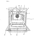
- Fig. 1 is a perspective view of an electric oven to which the present invention is applied;
- Fig. 2 is a cross-sectional view, taken along line I-I' of Fig. 1 , and illustrating a construction of a latch;
- Fig. 3 is a cross-sectional view, taken along line II-II' of Fig. 1 ;
- Fig. 4 is a view illustrating a state before a latch is not inserted in a second door opening/closing structure
- Fig. 5 is a view illustrating a state in which a latch is inserted to some extent and a first micro-switch is switched on;
- Fig. 6 is a view illustrating a state in which a latch is inserted completely and both a first and a second micro-switches are switched on;
- Figs. 7 and 8 are views illustrating that an alien material is inserted into the second door opening/closing structure
- Fig. 9 is a cross-sectional view, taken along line III-III' of Fig. 1 ;
- Fig. 10 is a side view of a first door opening/closing structure
- Figs. 11 through 13 are views sequentially illustrating a movement procedure of a hook in the first door opening/closing structure.
- Fig. 1 is a perspective view of an electric oven to which the present invention is applied.
- an electric oven 1 includes: a cavity 3 having a heating element in its inside; a door 30 formed on one side of the cavity 3, for selectively being opened/closed so that food may be put in and out; a pair of latches 20 provided to an inner side of the door 30; and a receiving hole 6 provided to one side of a housing 5, for fixing the door 30 by receiving the latch 20. Further, a hooked portion such as ring 65 formed on about a central portion of the inner side of the door 30, and a hook 60 for selectively being engaged with the hooked portion 65 in its inside and catching the hooked portion 65 so that the door 30 may not be opened when the door 30 is in a closed state.
- the latch 20 is inserted into the receiving hole 6 and fixed by a predetermined second door opening/closing structure formed in the receiving hole 6.
- the second door opening/closing structure detects insertion of the latch 20, thereby checking detection of the door 30. Further, the second door opening/closing structure performs a function of determining that the door is not closed when an alien material, not the latch 20, is inserted.
- a first door opening/closing structure making the hooked portion 65 caught on the hook 60 is provided.
- the first door opening/closing structure may be formed at an electric equipment unit in an upper portion of the cavity.
- the first door opening/closing structure can be understood as a door locking apparatus and the second door opening/closing structure can be understood as a door interlocking apparatus.
- the door interlocking apparatus is a predetermined structure for preventing the door from being detected as being closed using a door switch formed in an inside of the receiving hole 6 when a user inadvertently inserts a rod into the receiving hole 6. If the door is detected as being closed due to the inadvertently inserted rod and the electric oven starts to operate, a dangerous circumstance such as a fire in a room may be caused. Therefore, the door should be exactly detected as being closed only when the latch 20 is inserted reasonably.
- the electric oven 1 of the present invention further includes: an operation unit 4 for operating the electric oven 1 according to a user's intention; an exhaust port 2 for exhausting water vapor generated while food is being cooked in an inside of the cavity 3; a convection fan 7 formed in an inside of the cavity 3, for circulating an air in the inside of the cavity 3 convectively.
- a hot plate (not shown) is provided to an upper surface of the electric oven so that a cookware such as a pot may be placed and food is cooked.
- FIGs. 2 through 8 are views illustrating a door interlocking apparatus according the present invention. Referring to Figs. 2 through 8 , the door interlocking apparatus will be described in detail.
- Fig. 2 is a cross-sectional view, taken along line I-I' of Fig. 1 , and illustrating a construction of a latch.
- the latch 20 is formed in an inside of the door 30 and the latch 20 can stably operate at a set position.
- a latch pivot 21 functioning as a pivot of the latch 20 at a central position of a latch operation
- a latch spring 22 connecting a rear end of the latch 20 with a latch fixing part 23 to operate the latch 20 elastically.
- the latch 20 slightly rotates in a clockwise direction about the latch pivot 21 during a closing operation of the door 30 and once the latch 20 is inserted, the latch 20 rotates again in a counterclockwise direction.
- a position of the latch 20 may be stably maintained.
- a hook-shaped latch head 24 is formed on a front end of the latch 20, thus an insertion operation of the latch 20 can be stably performed and after the latch 20 is inserted, a hooking operation is performed and a position of the door 30 can be fixed.
- Fig. 3 is a cross-sectional view, taken along line II-II' of Fig. 1 and illustrating a second door opening/closing structure.
- a latch board 40 is formed in an inside of the receiving hole 6.
- the latch board 40 performs a function of detecting whether the latch 20 is inserted or not, together with a function of fixing a position of the latch 20. Further, if an alien material such as a pin, not the latch 20, is inserted, the latch board 40 may perform a function of detecting that the door is not closed.
- the latch board 40 includes: a plurality of operation parts 45, 48, and 50 to be moved by the latch head 24 when the latch 20 is inserted into an inside of the receiving hole 6; micro-switches 41 and 42 for detecting the insertion of the latch 20 by receiving movements of the operation parts; and a latch hooking part 53 for guiding the insertion operation of the latch 20 and fixing a position of the inserted latch 20.
- the operation parts includes: a first operation part 45 to be touched first when the latch 20 is inserted; a third operation part 50 pressed in cooperation with the first operation part 45; and a second operation part 48 sequentially moving after the first operation part 45 is moved.
- the first operation part 45 which is a plate-shaped member, rotates on a first pivot 46, and a pressing part 51 is extended from a predetermined position of the first operation part 45.
- the second operation part 48 has one end touched to the latch head 24 and other end touched to a second switch button 44 of the second micro-switch 42 so as to be rotated about the second pivot 49.
- the third operation part 50 one end is fixed to the first micro-switch 41 and other end is pressed by the pressing part 51 so as to make a first switch button 43 switched on.
- the operation parts are formed into a plate shapes, whereby cooperative operation of the operation parts can be swiftly performed.
- a spring 47 is interposed between other end of the first operation part 45 and the latch board 40.
- a position of the first operation part 45 can be supported by the spring 47.
- the first operation part 45 is set to rotate counterclockwise on the first pivot 46.
- the pressing part 51 and the third operation part 50 are not touched each other, thus the first micro-switch 41 is in an off-state.
- a terminal of the pressing part 51 pushes the second operation part 48 so that the second operation part 48 may be rotated counterclockwise.
- the second micro-switch 42 is also in an off-state.
- the first operation part 45 and the second operation part 48 are sequentially touched to the latch head 24.
- the first operation part 45 continuously moves the third operation part 50.
- the first micro-switch 41 is switched on by the third operation part 50
- the second micro-switch 42 is switched on by the second operation part 48.
- the micro-switches 41 and 42 are sequentially switched on, whereby the door 30 can be detected as being normally closed.
- switch-on operations of the micro-switches 41 and 42 are delivered to a controller of the electric oven, and an interval of the delivered continuous detection signal is judged, so that the door 30 is detected as being closed.
- the operation parts 45 and 48 are not operated continuously. In that case, it may be judged that the door 30 is not closed because other material, not the latch 20 is inserted.
- Figs. 4 through 6 are views sequentially illustrating an insertion process of the latch.
- Fig. 4 illustrates a state just before the latch is inserted
- Fig. 5 illustrates a state that the latch is inserted to some extent and the first micro-switch 41 is switched on
- Fig. 6 illustrates a state that the latch is inserted completely and the second micro-switch 42 is also switched on as well as the first micro-switch 41.
- the first operation part 45 is rotated counterclockwise by the spring 47 and the pressing part 51 only touches to the third operation part 50, thereby not applying any force on the third operation part 50.
- the first and the second micro-switches 41 and 42 are all in a switch-off state.
- the latch head 24 is touched to the first operation part 45, and the first operation part 45 is rotated clockwise on the first pivot 46. If the first operation part 45 is rotated, the pressing part 51 is rotated clockwise on the whole, pressing the third operation part 50. Then, the third operation part 50 presses the first switch button 43 so that the first micro-switch 41 may be switched on. Referring to Fig.
- the latch head 24 pushes the second operation part 48 to rotate the same clockwise. At this point, a terminal of the second operation part 48 presses the second switch button 44 so that the first micro-switch 42 may be switched on. Further, if the latch 20 is inserted completely, the latch head 24 is hooked on the latch hooking part 53, so that the latch 20 can be detached only when predetermined external force is applied. Thus, a position of the closed door 30 can be stably fixed.
- the micro-switches 41 and 42 are sequentially switched on during a series of operations of the operation parts 45, 48, and 50. According to an experiment, a time difference of about 4ms is generated.
- the continuous detection signal of the micro-switch is delivered to the controller of the electric oven so that whether the door is normally closed can be detected.
- a time difference of 4 ⁇ 1 ms may be judged as closing of the door.
- the sequential operation of the micro-switch by an interlocking apparatus of the second door opening/closing structure is intended to prevent a circuit for a safety apparatus provided to an inside of the micro-switch from being connected simultaneously. If the circuit for the safety apparatus operating in cooperation with the micro-switch is connected simultaneously to operate, a power switch is falsely operated, so that an arcing region, in which the electric oven automatically operates without an instruction of a user, may be generated.
- Figs. 7 and 8 illustrate an operation sequence of the second door opening/closing structure when a pin, not the latch is inserted into the second door opening/closing structure.
- the first micro-switch 41 may be normally switched on by the first operation part 45.
- the pin P requires a little more time to operate the second operation part 48 than the latch 20 because it may take a more time until the first operation part 45 is pushed to its end by the pin P to push the second operation part 48, and such a time may be at least more than 4ms.
- the second operation part 48 might not be pushed by the pin P, depending on cases.
- Figs. 9 through 13 illustrate the first door opening/closing structure as a door locking apparatus.
- the first door opening/closing structure is intended to prevent the door from being opened even by an external force from a user while a thermal decomposition cleaning is performed in the cavity, so that user's safety can be enhanced even more.
- Fig. 9 is a cross-sectional view taken along line III-III' of Fig. 1 , illustrating the first door opening/closing structure.
- the first door opening/closing structure includes: a hook 60 selectively hooked on the hooked portion 65; and a hook operation unit 80 for generating external force by which the hook 60 is operated.
- the hook operation unit 80 includes: a motor 70 for generating power; a cam operation shaft 71 extended to a lower side of the motor 70 so that the hook 60 may be operated in cooperation with the motor 70; a cam 72 on an eccentric position of which the cam operation shaft 71 is formed; and a cam guide 73 into which the cam 72 is inserted so that a predetermined hook operation is performed.
- a guide slot 61 having an elongated shape in an up and down direction is formed on each side of the cam guide 73, and a guide member 82 fixed to the hook operation unit 80 is provided in the guide slot 61 to guide a movement of the hook 60, are provided. Further, a micro-switch 81 performing on/off operation according to a rotational angle of the cam 72 is provided to control closing/releasing of the door.
- the guide slot 61 is formed obliquely at a predetermined angle of ⁇ so that the hook 60 may move in a direction inclined of a predetermined angle.
- Fig. 10 is a side view of the first door opening/closing structure. Referring to Fig. 10 , the motor 70, the cam operation shaft 71 extending downwardly from the motor 70, the cam 72 formed at the end of the cam operation shaft 71, and the micro-switch 81 are illustrated.
- the cam operation shaft 71 When the motor 70 is rotated, the cam operation shaft 71 is rotated.
- the cam operation shaft 71 rotates the cam 72 on the whole and the cam 72 pushes the cam guide 73 so that the hook 60 may be moved wholly in up and down directions. Further, when the hook 60 is moved in the up and down directions, the hook 60 is made to be moved in a predetermined direction only by interaction between the guide slot 61 and the guide member 82, whereby the hook 60 can be exactly hooked on the hooked portion 65. Further, it is also possible to make the rotation of the motor 70 stopped when the rotation of the cam operation shaft 71 is detected by the micro-switch 81, and the door may be judged to have been closed completely.
- Figs. 11 through 13 sequentially illustrate a movement process of the hook. Referring to Figs. 11 through 13 , the hooked portion 65, the cam 72, the cam operation shaft 71, and the guide member 82 are fixed and only the hook 60 is moved.
- the hook 60 is hooked on the hooked portion 65 so that the door 30 is closed. Under such a state, even if a user intends to open the door, the door would not be opened.
- the inside of the cavity may be in a state in which food's remnant is being thermally decomposed by high temperature.
- the cam operation shaft 71 is rotated, such that the cam 72 is rotated about the cam operation shaft 71.
- the cam operation shaft 71 forces the hook 60 to move on the whole by an operation of pushing/pulling the cam guide 73.
- the hook 60 is moved in a predetermined direction by an interaction between the guide member 82 and the guide slot 61. Particularly, since the guide slot 61 is obliquely formed from the upper left to the lower right, the hook 60 is also moved in the direction inclined toward the upper left in order to be completely detached from the hooked portion 65.
- Fig. 12 illustrates that the hook 60 has moved half of the whole movement distance with the cam rotated about 90°
- Fig. 13 illustrates that the hook 60 has moved completely the whole movement distance with the cam rotated about 180°.
- FIGs. 11 through 13 illustrate that the hook is moved to a door-opening direction, it is easily expected that the hook will be moved in a door-closing direction by movement of the cam 72 in an opposite direction.
- the hooked portion is formed in the door and the hook is formed in the main machine of the oven
- the hook and the hooked portion may be also formed in the door and the main machine, respectively, of course.
- the above configuration may be applied in the same way to the second door opening/closing structure.
- the first door opening/closing structure prevents the locked door from opening
- the second door opening/closing structure a door interlocking structure
- the first door opening/closing structure is operated only when the door is detected as being completely closed by the second door opening/closing structure.
- either the first or the second opening/closing structure may be selectively applied, depending on a specific application type of the electric oven. That is, by mounting the first door opening/closing structure, it is possible to safely use the electric oven when the door is closed.
- first and the second opening/closing structures perform their opening/closing operation using the latch and the hooked portion separately formed in the door
- first and the second opening/closing structures may also operate in cooperation with each other using a latch structure integrally formed in the door.
- an accident that may occur due to malfunction of the electric oven can be prevented in advance, and thereby a safety in using the electric oven can be enhanced even more.
- the structure of the door opening/closing apparatus of the electric oven is simplified, so that manufacturing cost can be reduced and the apparatus can be conveniently applied to products.
Landscapes
- Engineering & Computer Science (AREA)
- Chemical & Material Sciences (AREA)
- Combustion & Propulsion (AREA)
- Mechanical Engineering (AREA)
- General Engineering & Computer Science (AREA)
- Electric Ovens (AREA)
Claims (10)
- Elektrischer Ofen (1) mit einer Türöffnungs-/Schließvorrichtung, wobei der elektrische Ofen (1) aufweist:einen Garraum (3), in dem ein Hochtemperaturzustand geschaffen wird,eine Tür (30) zum selektiven Öffnen/Schließen des Garraums (3), undeine Türöffnungs-/Schließstruktur zum exakten Öffnen/Schließen der Tür (30),wobei die Türöffnungs-/Schließvorrichtung umfasst:einen Hakenabschnitt (65), der an der Tür (30) ausgebildet ist,einen Haken (60), der so angeordnet ist, dass er selektiv am Hakenabschnitt (65) eingreift,eine Nockenführung (73), undeinen Nocken (72), der in die Nockenführung (73) eingesetzt ist, zum Bewegen der Nockenführung (73), wobei der Nocken (72) durch eine externe Kraft gedreht werden kann,dadurch gekennzeichnet, dassder Hakenabschnitt (65) an einer Innenseite der Tür (30) ausgebildet ist, unddie Nockenführung (73) an einem Körper des Hakens (60) ausgebildet ist.
- Elektrischer Ofen (1) nach Anspruch 1, wobei der Körper des Hakens (60) einen Führungsschlitz (61) zum Führen einer Bewegung des Hakens (60) aufweist, sowie ein in den Führungsschlitz (61) eingesetztes Führungselement (82).
- Elektrischer Ofen (1) nach Anspruch 2, wobei der Führungsschlitz (61) schräg ausgebildet ist.
- Elektrischer Ofen (1) nach einem der Ansprüche 1 bis 3, ferner mit:einer an einer Innenseite der Tür (30) ausgebildeten Verriegelung (20),einem ersten (45) und einem zweiten Betätigungsteil (48), die so angeordnet sind, dass sie nacheinander von der Verriegelung (20) betätigt werden, undeinem ersten (41) und einem zweiten Mikroschalter (42), die so angeordnet sind, dass sie nacheinander durch die ersten und zweiten Betätigungsteile (45,48) eingeschaltet werden.
- Elektrischer Ofen (1) nach Anspruch 4, ferner mit einer Feder (47) zum Führen einer Position des ersten Betätigungsteils (45) durch Verbinden des ersten Betätigungsteils (45) mit einer Verriegelungsplatte (40).
- Elektrischer Ofen (1) nach Anspruch 4 oder 5, ferner mit einem dritten Betätigungsteil (50) zum Einschalten des ersten Mikroschalters (41) durch Zusammenwirken mit dem ersten Betätigungsteil (45).
- Elektrischer Ofen (1) nach einem der Ansprüche 4 bis 6, wobei die ersten und zweiten Betätigungsteile (45,48) sich an einem vorbestimmten Drehpunkt (47) drehen.
- Elektrischer Ofen (1) nach einem der Ansprüche 4 bis 7, ferner mit einem Verriegelungs-Einhakteil (53) zum reibungslosen Einführen der Verriegelung (20).
- Elektrischer Ofen (1) nach einem der Ansprüche 4 bis 8, wobei die ersten und zweiten Betätigungsteile (45,48) so angeordnet sind, dass sie selektiv berührt werden.
- Elektrischer Ofen (1) nach einem der Ansprüche 1 bis 9, wobei der Nocken (72) in die Nockenführung (73) so eingeführt ist, dass die Drehung des Nockens (72) den Haken (60) direkt in und außer Eingriff mit/von dem Hakenabschnitt (65) bewegt.
Applications Claiming Priority (4)
| Application Number | Priority Date | Filing Date | Title |
|---|---|---|---|
| KR1020040010015A KR101052104B1 (ko) | 2004-02-16 | 2004-02-16 | 전기오븐의 인터록 구조 |
| KR2004010015 | 2004-02-16 | ||
| KR20-2004-0004925U KR200349841Y1 (ko) | 2004-02-25 | 2004-02-25 | 전기오븐의 록킹구조 |
| KR2004004925 | 2004-02-25 |
Publications (2)
| Publication Number | Publication Date |
|---|---|
| EP1564497A1 EP1564497A1 (de) | 2005-08-17 |
| EP1564497B1 true EP1564497B1 (de) | 2008-08-27 |
Family
ID=34703459
Family Applications (1)
| Application Number | Title | Priority Date | Filing Date |
|---|---|---|---|
| EP20040027019 Expired - Lifetime EP1564497B1 (de) | 2004-02-16 | 2004-11-12 | Öffnungs- und Schliesssystem für eine Ofentür |
Country Status (3)
| Country | Link |
|---|---|
| EP (1) | EP1564497B1 (de) |
| DE (1) | DE602004016113D1 (de) |
| ES (1) | ES2309436T3 (de) |
Families Citing this family (2)
| Publication number | Priority date | Publication date | Assignee | Title |
|---|---|---|---|---|
| CN103791530A (zh) * | 2014-01-20 | 2014-05-14 | 中山东菱威力电器有限公司 | 一种下拉式开门的微波炉 |
| ITUB20152074A1 (it) * | 2015-07-10 | 2017-01-10 | Mcz Group S P A | Apparecchiatura di riscaldamento provvista di un dispositivo di sicurezza |
Family Cites Families (3)
| Publication number | Priority date | Publication date | Assignee | Title |
|---|---|---|---|---|
| US4764648A (en) * | 1987-08-28 | 1988-08-16 | Mcgill Manufacturing Co., Inc. | Switch assembly with actuator for sequentially activating two safety switches |
| FR2703137B1 (fr) * | 1993-03-23 | 1995-04-28 | Cepem | Dispositif de verrouillage de la porte d'un four. |
| US5493099A (en) * | 1994-12-28 | 1996-02-20 | Robertshaw Controls Company | Cooking apparatus, latching construction therefor and methods of making the same |
-
2004
- 2004-11-12 DE DE200460016113 patent/DE602004016113D1/de not_active Expired - Lifetime
- 2004-11-12 ES ES04027019T patent/ES2309436T3/es not_active Expired - Lifetime
- 2004-11-12 EP EP20040027019 patent/EP1564497B1/de not_active Expired - Lifetime
Also Published As
| Publication number | Publication date |
|---|---|
| DE602004016113D1 (de) | 2008-10-09 |
| EP1564497A1 (de) | 2005-08-17 |
| ES2309436T3 (es) | 2008-12-16 |
Similar Documents
| Publication | Publication Date | Title |
|---|---|---|
| US7556033B2 (en) | Door opening and closing system in electric oven | |
| CA3030194C (en) | Push-to-open / signal-to-open appliance door latching system with an integrated locking device | |
| CN106913224B (zh) | 烹饪器具 | |
| CA3031662A1 (en) | Locking mechanism and door opening control method | |
| EP3560288B1 (de) | Kochvorrichtung | |
| US6474702B1 (en) | Range door lock with nuisance latch | |
| EP1564497B1 (de) | Öffnungs- und Schliesssystem für eine Ofentür | |
| KR20230106837A (ko) | 조리기기 | |
| CN209733603U (zh) | 门锁组件及烤箱 | |
| US20250027655A1 (en) | Cooking appliance and controlling method thereof | |
| KR101157616B1 (ko) | 전자레인지의 도어 인터록장치 | |
| KR20230046852A (ko) | 조리기기 | |
| AU2004255017B8 (en) | Door opening and closing system in electronic oven | |
| US20250159769A1 (en) | Microwave appliances and protective door features | |
| CN116657987B (zh) | 烹饪器具的门锁装置和烹饪器具 | |
| KR102822734B1 (ko) | 래치 및 이를 포함한 조리기기 | |
| CN219864535U (zh) | 一种门锁结构及烹饪设备 | |
| CN216648093U (zh) | 开关组件和包括该开关组件的烹饪电器 | |
| CN218406978U (zh) | 一种门锁结构及烹饪电器 | |
| CN212277072U (zh) | 一种定时器旋钮结构及烤箱 | |
| KR20230155750A (ko) | 조리기기의 제어방법 | |
| CN116439589B (zh) | 烹饪器具 | |
| KR101052104B1 (ko) | 전기오븐의 인터록 구조 | |
| KR20250162222A (ko) | 조리기기 | |
| CN118414885A (zh) | 烹饪设备 |
Legal Events
| Date | Code | Title | Description |
|---|---|---|---|
| PUAI | Public reference made under article 153(3) epc to a published international application that has entered the european phase |
Free format text: ORIGINAL CODE: 0009012 |
|
| 17P | Request for examination filed |
Effective date: 20041112 |
|
| AK | Designated contracting states |
Kind code of ref document: A1 Designated state(s): AT BE BG CH CY CZ DE DK EE ES FI FR GB GR HU IE IS IT LI LU MC NL PL PT RO SE SI SK TR |
|
| AX | Request for extension of the european patent |
Extension state: AL HR LT LV MK YU |
|
| AKX | Designation fees paid |
Designated state(s): DE ES FR GB |
|
| 17Q | First examination report despatched |
Effective date: 20061212 |
|
| GRAP | Despatch of communication of intention to grant a patent |
Free format text: ORIGINAL CODE: EPIDOSNIGR1 |
|
| RTI1 | Title (correction) |
Free format text: DOOR OPENING/CLOSING APPARATUS FOR ELECTRIC OVEN |
|
| GRAS | Grant fee paid |
Free format text: ORIGINAL CODE: EPIDOSNIGR3 |
|
| GRAA | (expected) grant |
Free format text: ORIGINAL CODE: 0009210 |
|
| AK | Designated contracting states |
Kind code of ref document: B1 Designated state(s): DE ES FR GB |
|
| REG | Reference to a national code |
Ref country code: GB Ref legal event code: FG4D |
|
| REF | Corresponds to: |
Ref document number: 602004016113 Country of ref document: DE Date of ref document: 20081009 Kind code of ref document: P |
|
| REG | Reference to a national code |
Ref country code: ES Ref legal event code: FG2A Ref document number: 2309436 Country of ref document: ES Kind code of ref document: T3 |
|
| PLBE | No opposition filed within time limit |
Free format text: ORIGINAL CODE: 0009261 |
|
| STAA | Information on the status of an ep patent application or granted ep patent |
Free format text: STATUS: NO OPPOSITION FILED WITHIN TIME LIMIT |
|
| 26N | No opposition filed |
Effective date: 20090528 |
|
| PGFP | Annual fee paid to national office [announced via postgrant information from national office to epo] |
Ref country code: GB Payment date: 20131011 Year of fee payment: 10 |
|
| GBPC | Gb: european patent ceased through non-payment of renewal fee |
Effective date: 20141112 |
|
| REG | Reference to a national code |
Ref country code: FR Ref legal event code: PLFP Year of fee payment: 12 |
|
| PG25 | Lapsed in a contracting state [announced via postgrant information from national office to epo] |
Ref country code: GB Free format text: LAPSE BECAUSE OF NON-PAYMENT OF DUE FEES Effective date: 20141112 |
|
| REG | Reference to a national code |
Ref country code: FR Ref legal event code: PLFP Year of fee payment: 13 |
|
| REG | Reference to a national code |
Ref country code: FR Ref legal event code: PLFP Year of fee payment: 14 |
|
| PGFP | Annual fee paid to national office [announced via postgrant information from national office to epo] |
Ref country code: FR Payment date: 20171011 Year of fee payment: 14 |
|
| PGFP | Annual fee paid to national office [announced via postgrant information from national office to epo] |
Ref country code: ES Payment date: 20171214 Year of fee payment: 14 |
|
| PG25 | Lapsed in a contracting state [announced via postgrant information from national office to epo] |
Ref country code: FR Free format text: LAPSE BECAUSE OF NON-PAYMENT OF DUE FEES Effective date: 20181130 |
|
| REG | Reference to a national code |
Ref country code: ES Ref legal event code: FD2A Effective date: 20200103 |
|
| PG25 | Lapsed in a contracting state [announced via postgrant information from national office to epo] |
Ref country code: ES Free format text: LAPSE BECAUSE OF NON-PAYMENT OF DUE FEES Effective date: 20181113 |
|
| PGFP | Annual fee paid to national office [announced via postgrant information from national office to epo] |
Ref country code: DE Payment date: 20211006 Year of fee payment: 18 |
|
| REG | Reference to a national code |
Ref country code: DE Ref legal event code: R119 Ref document number: 602004016113 Country of ref document: DE |
|
| PG25 | Lapsed in a contracting state [announced via postgrant information from national office to epo] |
Ref country code: DE Free format text: LAPSE BECAUSE OF NON-PAYMENT OF DUE FEES Effective date: 20230601 |