EP1564464B1 - Soupape piézo-électrique - Google Patents
Soupape piézo-électrique Download PDFInfo
- Publication number
- EP1564464B1 EP1564464B1 EP20040002968 EP04002968A EP1564464B1 EP 1564464 B1 EP1564464 B1 EP 1564464B1 EP 20040002968 EP20040002968 EP 20040002968 EP 04002968 A EP04002968 A EP 04002968A EP 1564464 B1 EP1564464 B1 EP 1564464B1
- Authority
- EP
- European Patent Office
- Prior art keywords
- valve
- bending transducer
- section
- valve according
- piezoelectric
- Prior art date
- Legal status (The legal status is an assumption and is not a legal conclusion. Google has not performed a legal analysis and makes no representation as to the accuracy of the status listed.)
- Expired - Lifetime
Links
Images


Classifications
-
- F—MECHANICAL ENGINEERING; LIGHTING; HEATING; WEAPONS; BLASTING
- F16—ENGINEERING ELEMENTS AND UNITS; GENERAL MEASURES FOR PRODUCING AND MAINTAINING EFFECTIVE FUNCTIONING OF MACHINES OR INSTALLATIONS; THERMAL INSULATION IN GENERAL
- F16K—VALVES; TAPS; COCKS; ACTUATING-FLOATS; DEVICES FOR VENTING OR AERATING
- F16K31/00—Actuating devices; Operating means; Releasing devices
- F16K31/004—Actuating devices; Operating means; Releasing devices actuated by piezoelectric means
- F16K31/005—Piezoelectric benders
- F16K31/006—Piezoelectric benders having a free end
-
- Y—GENERAL TAGGING OF NEW TECHNOLOGICAL DEVELOPMENTS; GENERAL TAGGING OF CROSS-SECTIONAL TECHNOLOGIES SPANNING OVER SEVERAL SECTIONS OF THE IPC; TECHNICAL SUBJECTS COVERED BY FORMER USPC CROSS-REFERENCE ART COLLECTIONS [XRACs] AND DIGESTS
- Y10—TECHNICAL SUBJECTS COVERED BY FORMER USPC
- Y10T—TECHNICAL SUBJECTS COVERED BY FORMER US CLASSIFICATION
- Y10T137/00—Fluid handling
- Y10T137/8593—Systems
- Y10T137/86493—Multi-way valve unit
- Y10T137/86574—Supply and exhaust
- Y10T137/86622—Motor-operated
-
- Y—GENERAL TAGGING OF NEW TECHNOLOGICAL DEVELOPMENTS; GENERAL TAGGING OF CROSS-SECTIONAL TECHNOLOGIES SPANNING OVER SEVERAL SECTIONS OF THE IPC; TECHNICAL SUBJECTS COVERED BY FORMER USPC CROSS-REFERENCE ART COLLECTIONS [XRACs] AND DIGESTS
- Y10—TECHNICAL SUBJECTS COVERED BY FORMER USPC
- Y10T—TECHNICAL SUBJECTS COVERED BY FORMER US CLASSIFICATION
- Y10T137/00—Fluid handling
- Y10T137/8593—Systems
- Y10T137/86493—Multi-way valve unit
- Y10T137/86879—Reciprocating valve unit
- Y10T137/86895—Plural disk or plug
Definitions
- the invention relates to a piezoelectric valve, comprising a bending transducer arranged in a valve housing, which has a bearing portion mounted on the housing side and which has a freely ending working portion which extends in a valve chamber via two controllable valve openings in the form of an inflow opening and an outflow opening and by corresponding electrical control in a deflection plane transversely to its longitudinal direction is deflectable to release either of the two controllable valve openings either for connection to a work opening or to close by abutment on an associated valve seat.
- the bending transducer projects with its deflectable working section between two controllable valve openings, which is an inflow opening and an outflow opening.
- the electrically de-energized state of the working portion is taking on a blocking position at the inflow opening surrounding the valve seat, so that the inflow opening is closed.
- a voltage to the bending transducer of the working section undergoes a deflection force due to the piezoelectric effect, so that it is pivoted, wherein it releases the inflow and instead ultimately closes the outlet opening.
- EP 1207329 B1 describes a piezoelectric valve whose construction principle, in addition to a 3/2 functionality, also makes it possible, for example, to have 3/3 functionality.
- This piezo valve is provided with two adjacently arranged bending transducers, which are combined at a rear storage section to a Bieoderlerech. Each bending transducer protrudes over a controllable valve opening. By appropriately matched control of the two bending transducers, the controllable valve openings can be alternately or simultaneously released and shut off.
- the production of the bending transducer unit is relatively expensive.
- the two controllable valve openings on the same longitudinal side of the working portion, spaced from each other in the longitudinal direction, are arranged, wherein the working portion has two correspondingly spaced, the two controllable valve openings associated upstream or downstream control sections, and that at engage the working portion in the region of the inflow-side control section in addition to the bending transducer urged by the inflow-side control section is constantly acted upon in the direction of its closed position, wherein the biasing force is high enough to the inflow-side control section located in the release position downstream Control section to hold in the closed position.
- controllable valve openings can be placed differently in order, as needed, so that either the inflow opening or the outflow opening is closer to the storage section. Accordingly, there is also a different placement of the inflow-side control section, which is under the constant influence of the loading means.
- the bending transducer is suitably designed and arranged so that in his electrically de-energized neutral state both control sections with respect to their respective associated controllable valve opening occupy the closed position.
- starting from the neutral state can optionally implement a feed position or a venting position, wherein either the inflow opening or the outflow opening connected to the work opening and at the same time the other controllable valve opening is closed.
- the neutral state corresponds to a blocking position in which both controllable valve openings are sealed by the bending transducer.
- the bending transducer is expediently designed and arranged such that, in the electrically de-energized neutral state, one control section occupies the closed position and the other section assumes the release position with respect to the respectively associated controllable valve opening.
- This can be achieved, in particular, by employing a bending transducer which has an at least substantially linear extension in the neutral state and which is placed such that its longitudinal axis has a sloping course in the neutral state with respect to a valve seat plane containing the valve seats of the two controllable valve openings.
- the second control section initially also reaches the closed position, the associated supporting effect in the further course of the switching operation resulting in the control section, which initially occupies the closed position, lifting away from the associated valve seat and into the release position is deflected.
- 3/2-piezovalves can be realized in either a normally closed or normally open version.
- the bearing point for the bearing section of the bending transducer in the deflection plane is adjustable transversely to the longitudinal direction of the bending transducer, the angle of inclination of the bending transducer present in the neutral state can easily be varied in order to obtain the desired valve type.
- the adjustability of the storage section in conjunction with a 3/3-way valve allows an exact alignment of the bending transducer such that it occupies a simultaneously closed both controllable valve openings blocking position in the neutral state.
- the selectively connectable or closable working opening with respect to the controllable valve openings opens expediently on the same longitudinal side as the controllable valve openings into the valve chamber accommodating the working section of the bending transducer.
- the working opening is located in the longitudinal direction of the bending element between the two controllable valve openings.
- the storage can also be realized in that the storage section is pressed by itself on the valve housing supporting spring means, yielding in the deflection, against a valve housing fixed abutment.
- controllable valve openings with an opening cross-section which has an oblong shape at right angles to the deflection plane.
- the relevant controllable valve opening could be realized not only as a single opening, but in the form of a plurality of individual openings, which are arranged side by side transversely to the deflection plane and each having its own valve seat is assigned, on which the working section can be supported. In all cases, a reliable multiple support of the bending transducer in its longitudinal and transverse directions can be achieved in this way, which counteracts tilting about the longitudinal axis in each switching position.
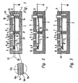
- Each of the piezo valves shown in the drawing has a generally two-part valve housing 1, which delimits an elongate valve chamber 2 in the interior.
- this valve chamber 2 is a longitudinal shape exhibiting, strip-shaped bending transducer 3, the rear end portion forms a storage section 4, with which it is mounted directly or via interposed storage means on the valve housing 1.
- the bearing is designated by reference numeral 5.
- controllable valve openings are open to the valve chamber 2 outlets of two valve channels in the form of an inflow channel 12 and a discharge channel 13.
- the inflow channel 12 is connected in operation of the piezo valve with a fluid to be controlled supplying pressure source P.
- the discharge channel 13 leads, depending on whether the piezoelectric valve is operated with a hydraulic medium or with compressed air, to a tank or to the atmosphere R.
- another working as a working channel 14 further valve channel opens with a working opening 9 also in the valve chamber 2 a. It is normally connected to a consumer to be driven, for example a fluid power operated drive.
- the bending transducers 3 preferably have (see enlarged detail in Fig. 1) a trimorphic structure with two with the interposition of an inner electrode 15 alongside each other attached elongated piezoelectric bodies 16a, 16b. Each piezoelectric body 16a, 16b is provided on the outside of the inner electrode 15 outside with an outer electrode 17a, 17b.
- a drive voltage 17b in selectively applied, which in the working section 6 causes a deflection force F A due to the reverse piezoelectric effect, tending to divert the working portion 6 in a Auslenkebene 22 relative to the valve housing 1 supported on the storage section 4.
- the drive voltage can be selectively applied so that the deflection force F A is oriented in either one of two opposite directions.
- a drive voltage is applied either between the inner electrode 15 and the one outer electrode 17a or between the inner electrode 15 and the other outer electrode 17b.
- the deflection level 22 extends in Fig. 1 to 11 and 14, 17 and 19 parallel to the plane and is perpendicular to the plane of extension of the strip-like bending transducer 3 as mentioned.
- the bending transducer 3 could also have a different structural design and be designed, for example, as a bimorph piezo winder. Also possible is a multi-layered design of the piezoelectric bodies 16a, 16b in order to obtain a multilayer bending transducer.
- the bending transducer 3 extends over both the inflow opening 7 and the outflow opening 8, these two valve openings being arranged on one and the same longitudinal side of the working section 6, with respect to which the working section 6 can approach or move away during the deflection movement. In other words, it is such a longitudinal side of the bending transducer 3, which is associated with one of the two large-scale bending transducer outer surfaces.
- the two controllable valve openings 7, 8 in the longitudinal direction of the working portion 6 are arranged at a distance from each other, so either - as in the case of the designs according to FIGS. 1 to 3 and 7 to 10 - the inflow opening 7 between the storage section 4 and the discharge opening.
- the working section 6 of the bending transducer 3 has a respective control section which, according to the assignment to the corresponding valve opening 7, 8, is designated as an inflow-side control section 24 or as a downstream control section 25 ,
- These control sections 24, 25 can be formed directly from one of the bending transducer layers or, as is the case with the exemplary embodiments, each consist of a suitable sealing material, fixed to the bending transducer 3 pad.
- the pads are rubber pads.
- the two controllable valve openings 7, 8 are each framed by a valve seat 26 raised with respect to adjacent valve housing surfaces.
- the raised valve seat design is not mandatory.
- Each control section 24, 25 is able to shut off the valve channel 12, 13 opposite it in a fluid-tight manner, when it is pressed against the associated valve seat 26 with a certain contact pressure.
- the working opening 9 is independent of the current position of the working section 6 open, so that a permanent connection between the working channel 14 and the valve chamber 2 is present.
- the working opening 9 is located on the same longitudinal side of the bending transducer 3 as the two controllable valve openings 7, 8. In favor of short flow paths, it is expediently placed between the two controllable valve openings 7, 8.
- Each piezo valve has in addition to the bending transducer 3 provided urging means 27 which engage in the region of the inflow-side control section 24 on the working section 6, and by the inflow-side control section 24 is constantly acted upon in the direction of its closed position.
- the loading means are preferably one between the working section 6 and the valve housing 1 effective spring device, and in particular by at least one at one end on the inner surface of the valve chamber 2 and the other end on the back of the working section 6 supporting mechanical compression spring.
- the application force should be so great that the pending in the inflow channel fluid pressure is not able to lift the located in the closed position inflow control section 24.
- the application force should be at least so high that the inflow-side control section 24 can be held in the closed position when the outflow-side control section is in the release position lifted from the associated valve seat.
- the piezoelectric valve shown in Fig. 1 to 3 is designed as a 3/3-way valve, so has three switching positions for linking the three valve ports 7, 8, 9.
- His bending transducer 3 has an electrically non-contacting neutral state at least substantially linear extent and is arranged in the valve chamber 2 so that both control sections 24, 25 rest on the opposite valve seat 26 and occupy the closed position.
- the longitudinal axis 28 of the bending transducer 3 extends at a distance approximately parallel to a two valve seats 26 containing valve seat plane 32. In this valve seat plane 32 is also the bearing point 5, so that the bending transducer 3 is supported fixed to the housing in its longitudinal direction at three locations.
- the inflow opening 7 Due to the loading means 27, which act on the bending transducer 3 in the longitudinal direction of the bending transducer 3 at the same height with the inflow opening 7, the inflow opening 7 is closed by the inflow-side control section 24 with a sufficiently high contact pressure to prevent lift-off by the impending fluid pressure ,
- the bending transducer 3 is controlled so that a Deflection force F A in the direction of the valve seats 26 having longitudinal side adjusts. This causes a deflection of the working portion 6 in the sense of bulging in the central region, wherein the inflow-side control section 24 is lifted from the inflow opening 7 by overcoming the pressing force of the biasing means 27 (FIG. 2).
- the venting position is to be set, in which the outflow opening 8 is connected via the valve chamber 2 to the work opening 9 and at the same time the inflow opening 7 is closed, the bending transducer 3 is actuated in the opposite direction, so that a deflecting force pointing away from the side of the valve seats 26 occurs F A stops.
- this leads to the outflow-side control section 25 assigned to the free end of the working section 6 pivoting away from the outflow opening 8 and lifting, while the inflow-side control section 24 is pressed against the inflow opening 7 by the loading means 27.
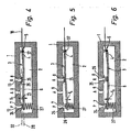
- the construction of the piezo valve shown in FIGS. 4 to 6 is identical to that described above.
- To receive the food item is here in the working section 6 causes a deflecting force F A pointing away from the side of the valve seats 26, which causes the working section 6 to be pivoted away from the inflow opening 7 in the area of the free end provided with the inflow-side control section 24, while at the same time the outflow-side control section 25 abuts due to the deflection of the bending transducer 3 on the valve seat 26 of the discharge opening 8.
- the piezo valves shown in FIGS. 7 to 10 have a 3/2 functionality and, if required, can be operated with a bending transducer whose working section 6 can exert a deflection force F A in only one direction.
- the piezo valves of FIGS. 7 to 10 differ from those of FIGS. 1 to 3 otherwise only in that the bearing 5 is positioned differently in the direction of the deflection movement 23, so that the bending transducer 3 in neutral neutral voltage state with respect to the valve seat plane 32 is set at an angle. This ensures that in the neutral state of a control section occupies the closed position and the other control section, the release position.
- the inclination of the bending transducer 3 in the neutral state is selected so that the inflow-side control section closes off the inflow opening 7, while the outflow-side control section 25 is lifted off the outflow opening 8 and releases it. It is thus a valve of the type "normally closed", wherein in the electrically de-energized neutral state, the venting position is given.
- the bending transducer 3 is excited so that the working section experiences a deflection force F A in the direction of the valve seats 26, so that it bulges in the central region and ultimately the state shown in FIG. 8 is obtained, which is described with reference to FIG is comparable.
- the piezo valve of FIGS. 9 and 10 is of the "normally open” type, with the feed position in the neutral state.
- the inclination of the bending transducer 3 with respect to the valve seat plane 32 is opposite here compared to the neutral state of Fig. 7, so that the downstream control section 25 abuts the discharge opening 8, while the inflow-side control section 24 is lifted from the inflow opening 7.
- the bending transducer is controlled such that the working section experiences a deflecting force F A pointing away from the side of the valve seats 26, which leads to the state shown in FIG. 10, which is comparable to that of FIG.
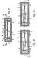
- the bearing 5 is adjustable in the deflection plane, as is the case with the piezo valves of FIGS. 1 to 3 and 7 to 10 (adjustment movement 33), the desired valve functionality or the desired valve type can be predetermined solely by the height-wise adjustment of the bearing 5 become.
- the selected setting results in the neutral state of the bending transducer 3, a different relative position to the valve seat plane 32 - either substantially parallel or inclined in one or the other direction - so that on the basis of a base valve an extremely flexible valve manufacturing using the same components is possible.
- the type of pivotal mounting shown in the exemplary embodiments of FIGS. 1 to 3 and 7 to 20 has proven to be particularly advantageous.
- the storage section 4 is clamped between itself on the valve housing 1 supporting spring means 34 and a valve housing fixed abutment in a certain extent compliant manner.
- the resilient bias causes the storage section 4 can pivot relative to the fixed abutment 35, wherein according to the current deflection, a more or less strong compression of the spring means 34 takes place, which compensates for the pivot angle.
- this type of storage is linked in an advantageous manner with the previously mentioned height adjustment for the bearing 5.
- the actuator 36 By adjusting the actuator 36, the position of the abutment 35 changes in the direction of the deflection movement 23, wherein the storage section 4 is taken and remains securely fixed in each set position by the spring means 34 acting on it.
- the degree of compression of the spring means 34 changes, but this does not affect the quality of the pivot bearing.
- the abutment 35 is fixedly arranged on the valve housing 1. This is associated with a simpler and cheaper production.
- the bending transducer 3 is mounted on the bearing point 5 via the plane perpendicular to the deflection 22, stationary Drehachsstoff 37 pivotally.
- These Drehachsstoff 37 are realized directly as a material axis of rotation, for example by at the two longitudinal edges of the bending transducer 3 projecting axle or the bending transducer 3 passing, both sides projecting shaft, wherein the protruding portions are respectively mounted on the valve housing while ensuring the desired rotational degree of freedom.
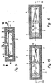
- controllable valve openings 7, 8 each consisting of a single opening, by an abutment 35 which defines a perpendicular to the deflection plane 22, linear abutment portion 42.
- the abutment 35 may be similar to hocker designed sharp edge.
- the bending transducer 3 is located with one of its control sections at points on one of the valve seats 26, while on the other hand it is supported linearly on the abutment 35. This results in the support configuration illustrated in FIGS. 18 and 20 by a triangle, the tip of the triangle in each case lying in the region of the control section which is supported on a valve seat 26.
- a comparatively statically defined three-point support for the bending transducer 3 can also be achieved in conjunction with an abutment 35 which, according to FIGS. 11 to 16, defines a punctiform abutment section 43 on which the support section 4 of the bending transducer 3 is supported.
- an abutment 35 which, according to FIGS. 11 to 16, defines a punctiform abutment section 43 on which the support section 4 of the bending transducer 3 is supported.
- valve opening 7, 8 to be controlled has an opening cross-section which has an oblong shape in a direction at right angles to the deflection plane 22, so that the valve opening 7, 8 in question also framing valve seat 26 has a corresponding longitudinal shape.
- the respective controllable valve opening 7, 8 could consist not only of a single opening but of a plurality of individual openings arranged in particular at right angles to the deflection plane 22.
- each individual opening has its own valve seat 26, wherein the transverse to the deflection 22 spaced arrangement of the valve seats 26 again a support for the bending transducer 3 is achieved, which prevents it from tilting or twisting about the longitudinal axis.
- Both embodiments have the further advantage that can be realized with them larger opening cross-sections without having to increase the opening dimensions in the longitudinal direction of the bending transducer 3.
Landscapes
- Engineering & Computer Science (AREA)
- General Engineering & Computer Science (AREA)
- Mechanical Engineering (AREA)
- Electrically Driven Valve-Operating Means (AREA)
- Fuel-Injection Apparatus (AREA)
Claims (18)
- Soupape piézoélectrique avec un transducteur de flexion (3) placé dans un boîtier de soupape (1), transducteur qui présente à une extrémité une section d'appui (4) soutenue dans le boîtier et qui possède une section de travail (6) se terminant librement, qui s'étend dans une chambre de soupape (2) sur deux ouvertures de soupape commandables prenant la forme d'une ouverture d'admission (7) et d'une ouverture d'évacuation (8) et qui, par une commande électrique appropriée, peut être déviée dans un plan de déviation (22) transversalement à sa direction longitudinale afin de libérer au choix chacune des deux ouvertures de soupape commandables (7, 8) afin d'établir une liaison avec une ouverture de travail (9) ou de la fermer par appui contre un siège de soupape (26) associé, caractérisée en ce que les deux ouvertures de soupape commandables (7, 8) sont placées sur le même côté longitudinal de la section de travail (6) à distance l'une de l'autre dans sa direction longitudinale, dans laquelle la section de travail (6) présente deux sections de commande (24, 25) côté admission resp. côté évacuation espacées de manière correspondante et associées aux deux ouvertures de soupape commandables (7, 8), et en ce que sur la section de travail (6) se mettent en prise, au niveau de la section de commande (24) côté admission, des moyens de sollicitation (27) prévus en plus du transducteur de flexion (3), par l'intermédiaire desquels la section de commande (24) côté admission est constamment sollicitée en direction d'une position de fermeture, la force de sollicitation étant suffisamment grande pour tenir la section de commande (24) côté admission dans la position de fermeture quand la section de commande (25) côté évacuation se trouve dans la position d'ouverture.
- Soupape piézoélectrique selon la revendication 1, caractérisée en ce que l'ouverture d'admission (7) est placée entre la section d'appui (4) et l'ouverture d'évacuation (8).
- Soupape piézoélectrique selon la revendication 1, caractérisée en ce que l'ouverture d'évacuation (8) est placée entre la section d'appui (4) et l'ouverture d'admission (7).
- Soupape piézoélectrique selon l'une des revendications 1 à 3, caractérisée en ce que le transducteur de flexion (3) est conformé et disposé de sorte que, à l'état neutre sans tension électrique, les deux sections de commande (24, 25) prennent la position de fermeture par rapport à l'ouverture de soupape (7, 8) qui leur est respectivement associée, le transducteur de flexion (3) pouvant être commandé électriquement de telle sorte que sa section de travail (6) subisse une force de déviation au choix dans l'une ou l'autre direction depuis l'état neutre.
- Soupape piézoélectrique selon la revendication 4, caractérisée en ce que le transducteur de flexion (3) présente à l'état neutre une projection au moins sensiblement rectiligne, son axe longitudinal (28) étant orienté pour l'essentiel parallèlement à un plan de sièges de soupape (32) contenant les sièges de soupape (26) des deux ouvertures de soupape commandables (7, 8).
- Soupape piézoélectrique selon l'une des revendications 1 à 3, caractérisée en ce que le transducteur de flexion (3) est conformé et disposé de sorte que, à l'état neutre sans tension électrique, une section de commande se place dans la position de fermeture et l'autre section de commande se place dans la position d'ouverture.
- Soupape piézoélectrique selon la revendication 6, caractérisée en ce que le transducteur de flexion (3) présente à l'état neutre une projection au moins sensiblement rectiligne, son axe longitudinal (28) présentant une inclinaison par rapport à un plan de sièges de soupape (32) contenant les sièges de soupape (26) des deux ouvertures de soupape commandables (7, 8).
- Soupape piézoélectrique selon l'une des revendications 1 à 7, caractérisée en ce que le point d'appui (5) de la section d'appui (4) du transducteur de flexion (3) est ajustable dans le plan de déviation (22) transversalement à la direction longitudinale du transducteur de flexion (3).
- Soupape piézoélectrique selon la revendication 8, caractérisée en ce que, par un ajustement correspondant du point d'appui (5), la position inclinée du transducteur de flexion (3) à l'état neutre peut être réglée au choix de sorte que l'une ou l'autre section de commande se place dans la position de fermeture et l'autre section de commande dans la position d'ouverture.
- Soupape piézoélectrique selon l'une des revendications 1 à 9, caractérisée en ce que les moyens de sollicitation (27) sont formés par un dispositif à ressort actif entre la section de travail (6) et le boîtier de soupape (1).
- Soupape piézoélectrique selon l'une des revendications 1 à 10, caractérisée en ce que l'ouverture de travail (9) est placée du même côté longitudinal du transducteur de flexion (3) que les ouvertures commandables (7, 8).
- Soupape piézoélectrique selon l'une des revendications 1 à 11, caractérisée en ce que le transducteur de flexion (3) est monté pivotant sur le point d'appui (5) par rapport au boîtier de soupape (1).
- Soupape piézoélectrique selon la revendication 12, caractérisée en ce que le transducteur de flexion (3) est monté pivotant au point d'appui (5) par l'intermédiaire de moyens à axe de rotation (37) fixes perpendiculaires au plan de déviation (22).
- Soupape piézoélectrique selon la revendication 12, caractérisée en ce que la section d'appui (4) est ajustable élastiquement au point d'appui (5) contre un contre-appui (35) solidaire du boîtier de soupape, par des moyens à ressort (34) s'appuyant sur le boîtier de soupape (1).
- Soupape piézoélectrique selon la revendication 14, caractérisée en ce que le contre-appui (35) est ajustable par rapport au boîtier de soupape (1).
- Soupape piézoélectrique selon la revendication 14 ou 15, caractérisée en ce que le contre-appui (35) définit une section de contre-appui (42, 43) ponctuelle ou linéaire, perpendiculaire au plan de déviation, contre laquelle s'appuie la section d'appui (4) du transducteur de flexion (3).
- Soupape piézoélectrique selon l'une des revendications 1 à 16, caractérisée en ce qu'au moins l'une des deux ouvertures commandables (7, 8) présente une section d'ouverture de forme oblongue perpendiculairement au plan de déviation (22).
- Soupape piézoélectrique selon l'une des revendications 1 à 17, caractérisée en ce qu'au moins l'une des deux ouvertures de soupape commandables (7, 8) est formée de plusieurs ouvertures distinctes juxtaposées perpendiculairement au plan de déviation (22).
Priority Applications (5)
| Application Number | Priority Date | Filing Date | Title |
|---|---|---|---|
| DK04002968T DK1564464T3 (da) | 2004-02-11 | 2004-02-11 | Piezoventil |
| AT04002968T ATE323861T1 (de) | 2004-02-11 | 2004-02-11 | Piezoventil |
| DE200450000445 DE502004000445D1 (de) | 2004-02-11 | 2004-02-11 | Piezoventil |
| EP20040002968 EP1564464B1 (fr) | 2004-02-11 | 2004-02-11 | Soupape piézo-électrique |
| US11/052,524 US7322376B2 (en) | 2004-02-11 | 2005-02-07 | Piezoelectric valve |
Applications Claiming Priority (1)
| Application Number | Priority Date | Filing Date | Title |
|---|---|---|---|
| EP20040002968 EP1564464B1 (fr) | 2004-02-11 | 2004-02-11 | Soupape piézo-électrique |
Publications (2)
| Publication Number | Publication Date |
|---|---|
| EP1564464A1 EP1564464A1 (fr) | 2005-08-17 |
| EP1564464B1 true EP1564464B1 (fr) | 2006-04-19 |
Family
ID=34684658
Family Applications (1)
| Application Number | Title | Priority Date | Filing Date |
|---|---|---|---|
| EP20040002968 Expired - Lifetime EP1564464B1 (fr) | 2004-02-11 | 2004-02-11 | Soupape piézo-électrique |
Country Status (5)
| Country | Link |
|---|---|
| US (1) | US7322376B2 (fr) |
| EP (1) | EP1564464B1 (fr) |
| AT (1) | ATE323861T1 (fr) |
| DE (1) | DE502004000445D1 (fr) |
| DK (1) | DK1564464T3 (fr) |
Cited By (1)
| Publication number | Priority date | Publication date | Assignee | Title |
|---|---|---|---|---|
| WO2013079083A1 (fr) | 2011-12-02 | 2013-06-06 | Festo Ag & Co. Kg | Système de soupape |
Families Citing this family (32)
| Publication number | Priority date | Publication date | Assignee | Title |
|---|---|---|---|---|
| CA2613853A1 (fr) * | 2006-12-11 | 2008-06-11 | Fisher & Paykel Appliances Limited | Vanne a reglage de debit variable |
| DE102007038545A1 (de) * | 2007-08-16 | 2009-02-19 | Robert Bosch Gmbh | Programmierbarer Filterprozessor |
| US8978757B2 (en) | 2008-07-17 | 2015-03-17 | Schlumberger Technology Corporation | Remote actuation testing tool for high pressure differential downhole environments |
| GB2474212B (en) * | 2008-07-17 | 2012-04-25 | Schlumberger Holdings | Downhole piezoelectric devices |
| US8082952B2 (en) * | 2008-08-22 | 2011-12-27 | Hamilton Sundstrand Corporation | Piezoelectric bending element actuator for servo valve |
| US8414366B2 (en) * | 2008-10-20 | 2013-04-09 | GM Global Technology Operations LLC | Active material enabled pressure release valves and methods of use |
| TWI435196B (zh) | 2009-10-15 | 2014-04-21 | 派伏塔系統公司 | 氣體流量控制方法及裝置 |
| US9400004B2 (en) | 2010-11-29 | 2016-07-26 | Pivotal Systems Corporation | Transient measurements of mass flow controllers |
| US8631825B2 (en) * | 2010-12-22 | 2014-01-21 | Inzi Controls Co., Ltd. | Piezo valve |
| EP2518378B1 (fr) * | 2011-04-28 | 2013-12-25 | Inzi Controls Co., Ltd. | Vanne piézo-électrique |
| US9683672B2 (en) * | 2012-08-16 | 2017-06-20 | Festo Ag & Co. Kg | Fluid valve |
| KR101386671B1 (ko) * | 2012-11-29 | 2014-04-21 | 인지컨트롤스 주식회사 | 피에조밸브 및 이를 위한 제조방법 |
| DE102012023532A1 (de) * | 2012-11-30 | 2014-06-05 | Wabco Gmbh | Elektropneumatisches Ventil |
| WO2014201032A1 (fr) * | 2013-06-11 | 2014-12-18 | Illinois Tool Works Inc. | Clapet de type piézo à haut débit |
| JP6938460B2 (ja) | 2015-07-10 | 2021-09-22 | ピヴォタル システムズ コーポレーション | ガス流制御のための方法および装置 |
| US11199771B2 (en) | 2016-10-20 | 2021-12-14 | Asml Netherlands B.V. | Pressure control valve, a fluid handling structure for lithographic apparatus and a lithographic apparatus |
| DE102017200308B4 (de) * | 2017-01-10 | 2021-07-08 | Fraunhofer-Gesellschaft zur Förderung der angewandten Forschung e.V. | Mikromechanische Bauelemente mit mechanischen Aktuatoren |
| DE102017204662C5 (de) * | 2017-03-21 | 2021-02-25 | Conti Temic Microelectronic Gmbh | Pneumatisches Ventil |
| WO2019215668A1 (fr) | 2018-05-11 | 2019-11-14 | Matthews International Corporation | Micro-soupapes destinées à être utilisées dans des ensembles à jet |
| MX2020012074A (es) | 2018-05-11 | 2021-03-09 | Matthews Int Corp | Sistemas y métodos para sellar microválvulas para su uso en conjuntos de chorros. |
| WO2019215671A2 (fr) | 2018-05-11 | 2019-11-14 | Matthews International Corporation | Procédés de fabrication de micro-soupapes et ensembles d'éjection comprenant de telles micro-soupapes |
| WO2019215672A1 (fr) | 2018-05-11 | 2019-11-14 | Matthews International Corporation | Systèmes et procédés de commande du fonctionnement de micro-vannes destinées à être utilisées dans des ensembles d'éjection |
| US11186084B2 (en) | 2018-05-11 | 2021-11-30 | Matthews International Corporation | Electrode structures for micro-valves for use in jetting assemblies |
| CA3156779A1 (fr) | 2019-11-01 | 2021-05-06 | Matthews International Corporation | Systemes de depot sans contact comprenant des ensembles de projection |
| CN112066005B (zh) * | 2020-08-17 | 2022-06-24 | 费尔顿技术(上海)有限公司 | 压电先导阀 |
| CN112081971B (zh) * | 2020-08-17 | 2022-05-20 | 费尔顿技术(上海)有限公司 | 压电式气体流量控制阀 |
| US12178996B2 (en) * | 2020-09-18 | 2024-12-31 | Carefusion 303, Inc. | Pressure actuated uni-directional flow control device for gravity IV sets |
| CN115507213B (zh) * | 2021-06-22 | 2025-05-06 | 科际精密股份有限公司 | 致动装置 |
| TWM617111U (zh) * | 2021-06-22 | 2021-09-11 | 科際精密股份有限公司 | 致動裝置 |
| CN115507214B (zh) * | 2021-06-22 | 2024-12-03 | 科际精密股份有限公司 | 气压调节装置及其气压调节方法 |
| US12253143B2 (en) | 2021-06-22 | 2025-03-18 | Koge Micro Tech Co., Ltd. | Actuating device |
| DE102022125517A1 (de) | 2022-10-04 | 2024-04-04 | Aventics Gmbh | Systeme und Verfahren für piezoelektrische Ventile |
Family Cites Families (13)
| Publication number | Priority date | Publication date | Assignee | Title |
|---|---|---|---|---|
| US4474212A (en) * | 1981-05-11 | 1984-10-02 | Harper-Wyman Company | Proportional flow control valve |
| US4492360A (en) * | 1982-06-07 | 1985-01-08 | The Lee Company | Piezoelectric valve |
| US4450375A (en) * | 1982-11-12 | 1984-05-22 | Kiwi Coders Corporation | Piezoelectric fluid control device |
| US4629926A (en) * | 1985-10-21 | 1986-12-16 | Kiwi Coders Corporation | Mounting for piezoelectric bender of fluid control device |
| CH681168A5 (en) * | 1989-11-10 | 1993-01-29 | Westonbridge Int Ltd | Micro-pump for medicinal dosing |
| AT396392B (de) * | 1991-09-30 | 1993-08-25 | Hoerbiger Fluidtechnik Gmbh | Piezo-ventil |
| DE4320909C1 (de) * | 1993-06-18 | 1994-06-01 | Siemens Ag | Servoventil |
| DE19648730C2 (de) * | 1996-11-25 | 1998-11-19 | Fraunhofer Ges Forschung | Piezoelektrisch betätigtes Mikroventil |
| US6193029B1 (en) | 1997-07-08 | 2001-02-27 | Active Control Experts, Inc. | Damper and valve |
| DE19854620C2 (de) * | 1998-11-26 | 2001-05-17 | Festo Ag & Co | Ventileinrichtung, insbesondere Verstärker |
| EP1158182B1 (fr) * | 2000-05-25 | 2004-12-08 | FESTO AG & Co | Agencement de soupape |
| ATE235661T1 (de) * | 2000-11-20 | 2003-04-15 | Festo Ag & Co | Piezoventil |
| DE10311238A1 (de) * | 2003-03-14 | 2004-10-07 | Festo Ag & Co. | Verfahren zur Herstellung eines Ventils |
-
2004
- 2004-02-11 EP EP20040002968 patent/EP1564464B1/fr not_active Expired - Lifetime
- 2004-02-11 DE DE200450000445 patent/DE502004000445D1/de not_active Expired - Lifetime
- 2004-02-11 AT AT04002968T patent/ATE323861T1/de active
- 2004-02-11 DK DK04002968T patent/DK1564464T3/da active
-
2005
- 2005-02-07 US US11/052,524 patent/US7322376B2/en not_active Expired - Fee Related
Cited By (3)
| Publication number | Priority date | Publication date | Assignee | Title |
|---|---|---|---|---|
| WO2013079083A1 (fr) | 2011-12-02 | 2013-06-06 | Festo Ag & Co. Kg | Système de soupape |
| CN103946612A (zh) * | 2011-12-02 | 2014-07-23 | 费斯托股份有限两合公司 | 阀组件 |
| CN103946612B (zh) * | 2011-12-02 | 2016-02-24 | 费斯托股份有限两合公司 | 阀组件 |
Also Published As
| Publication number | Publication date |
|---|---|
| US7322376B2 (en) | 2008-01-29 |
| US20050199301A1 (en) | 2005-09-15 |
| DE502004000445D1 (de) | 2006-05-24 |
| ATE323861T1 (de) | 2006-05-15 |
| EP1564464A1 (fr) | 2005-08-17 |
| DK1564464T3 (da) | 2006-05-29 |
Similar Documents
| Publication | Publication Date | Title |
|---|---|---|
| EP1564464B1 (fr) | Soupape piézo-électrique | |
| EP1207329B1 (fr) | Soupape piezoélectrique | |
| DE69916264T2 (de) | Elektrisch regelbares ventil | |
| EP1758007B1 (fr) | Régulateur de position actionné par fluide | |
| DE3608550A1 (de) | Piezo-elektrisch betaetigbares ventil | |
| EP2275729B1 (fr) | Soupape | |
| EP1158182A1 (fr) | Agencement de soupape | |
| EP1026407A1 (fr) | Elément de commande fluidique | |
| EP2017511B1 (fr) | Soupape piézoélectrique | |
| EP3414482B1 (fr) | Distributeur proportionnel | |
| DE102010035263B4 (de) | Piezoventil | |
| EP2193298B1 (fr) | Soupape | |
| EP1411285B1 (fr) | Soupape piézo-électrique | |
| DE29718306U1 (de) | Piezoventil | |
| DE102008056751A1 (de) | Fluidikvorrichtung mit normal-geschlossener Durchlassöffnung | |
| DE102020103476B4 (de) | Ventilantrieb und Ventil | |
| EP0145859B1 (fr) | Dispositif de soupape avec organe de commande piézo-électrique ou magnéto-strictif | |
| EP2846070B1 (fr) | Électrovanne | |
| DE102017130199B4 (de) | Folienwandler, Ventil, Pumpe sowie Verfahren zum Betreiben einer Pumpe | |
| DE102009010312B3 (de) | Biegewandlerventil | |
| DE102015113164A1 (de) | Fluidisches Steuerelement | |
| EP1970608A1 (fr) | Valve d'étranglement | |
| DE20210042U1 (de) | Piezoelektrische Aktoreinrichtung | |
| DE20019705U1 (de) | Piezo-Biegewandlereinheit und damit ausgestattetes Piezoventil | |
| DE102020200172B4 (de) | Ventilanordnung |
Legal Events
| Date | Code | Title | Description |
|---|---|---|---|
| PUAI | Public reference made under article 153(3) epc to a published international application that has entered the european phase |
Free format text: ORIGINAL CODE: 0009012 |
|
| 17P | Request for examination filed |
Effective date: 20040907 |
|
| AK | Designated contracting states |
Kind code of ref document: A1 Designated state(s): AT BE BG CH CY CZ DE DK EE ES FI FR GB GR HU IE IT LI LU MC NL PT RO SE SI SK TR |
|
| AX | Request for extension of the european patent |
Extension state: AL LT LV MK |
|
| GRAP | Despatch of communication of intention to grant a patent |
Free format text: ORIGINAL CODE: EPIDOSNIGR1 |
|
| GRAS | Grant fee paid |
Free format text: ORIGINAL CODE: EPIDOSNIGR3 |
|
| GRAA | (expected) grant |
Free format text: ORIGINAL CODE: 0009210 |
|
| AK | Designated contracting states |
Kind code of ref document: B1 Designated state(s): AT BE BG CH CY CZ DE DK EE ES FI FR GB GR HU IE IT LI LU MC NL PT RO SE SI SK TR |
|
| PG25 | Lapsed in a contracting state [announced via postgrant information from national office to epo] |
Ref country code: CZ Free format text: LAPSE BECAUSE OF FAILURE TO SUBMIT A TRANSLATION OF THE DESCRIPTION OR TO PAY THE FEE WITHIN THE PRESCRIBED TIME-LIMIT Effective date: 20060419 Ref country code: IT Free format text: LAPSE BECAUSE OF FAILURE TO SUBMIT A TRANSLATION OF THE DESCRIPTION OR TO PAY THE FEE WITHIN THE PRESCRIBED TIME-LIMIT;WARNING: LAPSES OF ITALIAN PATENTS WITH EFFECTIVE DATE BEFORE 2007 MAY HAVE OCCURRED AT ANY TIME BEFORE 2007. THE CORRECT EFFECTIVE DATE MAY BE DIFFERENT FROM THE ONE RECORDED. Effective date: 20060419 Ref country code: RO Free format text: LAPSE BECAUSE OF FAILURE TO SUBMIT A TRANSLATION OF THE DESCRIPTION OR TO PAY THE FEE WITHIN THE PRESCRIBED TIME-LIMIT Effective date: 20060419 Ref country code: SK Free format text: LAPSE BECAUSE OF FAILURE TO SUBMIT A TRANSLATION OF THE DESCRIPTION OR TO PAY THE FEE WITHIN THE PRESCRIBED TIME-LIMIT Effective date: 20060419 Ref country code: SI Free format text: LAPSE BECAUSE OF FAILURE TO SUBMIT A TRANSLATION OF THE DESCRIPTION OR TO PAY THE FEE WITHIN THE PRESCRIBED TIME-LIMIT Effective date: 20060419 Ref country code: FI Free format text: LAPSE BECAUSE OF FAILURE TO SUBMIT A TRANSLATION OF THE DESCRIPTION OR TO PAY THE FEE WITHIN THE PRESCRIBED TIME-LIMIT Effective date: 20060419 Ref country code: IE Free format text: LAPSE BECAUSE OF FAILURE TO SUBMIT A TRANSLATION OF THE DESCRIPTION OR TO PAY THE FEE WITHIN THE PRESCRIBED TIME-LIMIT Effective date: 20060419 |
|
| REG | Reference to a national code |
Ref country code: GB Ref legal event code: FG4D Free format text: NOT ENGLISH |
|
| REG | Reference to a national code |
Ref country code: CH Ref legal event code: NV Representative=s name: TROESCH SCHEIDEGGER WERNER AG |
|
| AKX | Designation fees paid |
Designated state(s): AT BE BG CH CY CZ DE DK EE ES FI FR GB GR HU IE IT LI LU MC NL PT RO SE SI SK TR |
|
| GBT | Gb: translation of ep patent filed (gb section 77(6)(a)/1977) |
Effective date: 20060419 |
|
| REF | Corresponds to: |
Ref document number: 502004000445 Country of ref document: DE Date of ref document: 20060524 Kind code of ref document: P |
|
| REG | Reference to a national code |
Ref country code: IE Ref legal event code: FG4D Free format text: LANGUAGE OF EP DOCUMENT: GERMAN |
|
| PG25 | Lapsed in a contracting state [announced via postgrant information from national office to epo] |
Ref country code: SE Free format text: LAPSE BECAUSE OF FAILURE TO SUBMIT A TRANSLATION OF THE DESCRIPTION OR TO PAY THE FEE WITHIN THE PRESCRIBED TIME-LIMIT Effective date: 20060719 |
|
| PG25 | Lapsed in a contracting state [announced via postgrant information from national office to epo] |
Ref country code: ES Free format text: LAPSE BECAUSE OF FAILURE TO SUBMIT A TRANSLATION OF THE DESCRIPTION OR TO PAY THE FEE WITHIN THE PRESCRIBED TIME-LIMIT Effective date: 20060730 |
|
| PG25 | Lapsed in a contracting state [announced via postgrant information from national office to epo] |
Ref country code: PT Free format text: LAPSE BECAUSE OF FAILURE TO SUBMIT A TRANSLATION OF THE DESCRIPTION OR TO PAY THE FEE WITHIN THE PRESCRIBED TIME-LIMIT Effective date: 20060919 |
|
| REG | Reference to a national code |
Ref country code: IE Ref legal event code: FD4D |
|
| ET | Fr: translation filed | ||
| PG25 | Lapsed in a contracting state [announced via postgrant information from national office to epo] |
Ref country code: MC Free format text: LAPSE BECAUSE OF NON-PAYMENT OF DUE FEES Effective date: 20070228 |
|
| PLBE | No opposition filed within time limit |
Free format text: ORIGINAL CODE: 0009261 |
|
| STAA | Information on the status of an ep patent application or granted ep patent |
Free format text: STATUS: NO OPPOSITION FILED WITHIN TIME LIMIT |
|
| 26N | No opposition filed |
Effective date: 20070122 |
|
| BERE | Be: lapsed |
Owner name: FESTO A.G. & CO Effective date: 20070228 |
|
| PG25 | Lapsed in a contracting state [announced via postgrant information from national office to epo] |
Ref country code: BE Free format text: LAPSE BECAUSE OF NON-PAYMENT OF DUE FEES Effective date: 20070228 |
|
| PG25 | Lapsed in a contracting state [announced via postgrant information from national office to epo] |
Ref country code: GR Free format text: LAPSE BECAUSE OF FAILURE TO SUBMIT A TRANSLATION OF THE DESCRIPTION OR TO PAY THE FEE WITHIN THE PRESCRIBED TIME-LIMIT Effective date: 20060720 |
|
| PG25 | Lapsed in a contracting state [announced via postgrant information from national office to epo] |
Ref country code: BG Free format text: LAPSE BECAUSE OF FAILURE TO SUBMIT A TRANSLATION OF THE DESCRIPTION OR TO PAY THE FEE WITHIN THE PRESCRIBED TIME-LIMIT Effective date: 20060719 |
|
| PG25 | Lapsed in a contracting state [announced via postgrant information from national office to epo] |
Ref country code: EE Free format text: LAPSE BECAUSE OF FAILURE TO SUBMIT A TRANSLATION OF THE DESCRIPTION OR TO PAY THE FEE WITHIN THE PRESCRIBED TIME-LIMIT Effective date: 20060419 |
|
| PGFP | Annual fee paid to national office [announced via postgrant information from national office to epo] |
Ref country code: DK Payment date: 20090213 Year of fee payment: 6 |
|
| PGFP | Annual fee paid to national office [announced via postgrant information from national office to epo] |
Ref country code: NL Payment date: 20090224 Year of fee payment: 6 |
|
| PG25 | Lapsed in a contracting state [announced via postgrant information from national office to epo] |
Ref country code: LU Free format text: LAPSE BECAUSE OF NON-PAYMENT OF DUE FEES Effective date: 20070211 Ref country code: CY Free format text: LAPSE BECAUSE OF FAILURE TO SUBMIT A TRANSLATION OF THE DESCRIPTION OR TO PAY THE FEE WITHIN THE PRESCRIBED TIME-LIMIT Effective date: 20060419 |
|
| PG25 | Lapsed in a contracting state [announced via postgrant information from national office to epo] |
Ref country code: TR Free format text: LAPSE BECAUSE OF FAILURE TO SUBMIT A TRANSLATION OF THE DESCRIPTION OR TO PAY THE FEE WITHIN THE PRESCRIBED TIME-LIMIT Effective date: 20060419 Ref country code: HU Free format text: LAPSE BECAUSE OF FAILURE TO SUBMIT A TRANSLATION OF THE DESCRIPTION OR TO PAY THE FEE WITHIN THE PRESCRIBED TIME-LIMIT Effective date: 20061020 |
|
| REG | Reference to a national code |
Ref country code: NL Ref legal event code: V1 Effective date: 20100901 |
|
| REG | Reference to a national code |
Ref country code: DK Ref legal event code: EBP |
|
| PG25 | Lapsed in a contracting state [announced via postgrant information from national office to epo] |
Ref country code: DK Free format text: LAPSE BECAUSE OF NON-PAYMENT OF DUE FEES Effective date: 20100228 Ref country code: NL Free format text: LAPSE BECAUSE OF NON-PAYMENT OF DUE FEES Effective date: 20100901 |
|
| PGFP | Annual fee paid to national office [announced via postgrant information from national office to epo] |
Ref country code: IT Payment date: 20150223 Year of fee payment: 12 |
|
| PGFP | Annual fee paid to national office [announced via postgrant information from national office to epo] |
Ref country code: GB Payment date: 20150122 Year of fee payment: 12 |
|
| REG | Reference to a national code |
Ref country code: FR Ref legal event code: PLFP Year of fee payment: 13 |
|
| PGFP | Annual fee paid to national office [announced via postgrant information from national office to epo] |
Ref country code: CH Payment date: 20160222 Year of fee payment: 13 |
|
| PGFP | Annual fee paid to national office [announced via postgrant information from national office to epo] |
Ref country code: FR Payment date: 20160222 Year of fee payment: 13 |
|
| GBPC | Gb: european patent ceased through non-payment of renewal fee |
Effective date: 20160211 |
|
| PG25 | Lapsed in a contracting state [announced via postgrant information from national office to epo] |
Ref country code: IT Free format text: LAPSE BECAUSE OF NON-PAYMENT OF DUE FEES Effective date: 20160211 |
|
| PG25 | Lapsed in a contracting state [announced via postgrant information from national office to epo] |
Ref country code: GB Free format text: LAPSE BECAUSE OF NON-PAYMENT OF DUE FEES Effective date: 20160211 |
|
| PGFP | Annual fee paid to national office [announced via postgrant information from national office to epo] |
Ref country code: AT Payment date: 20170217 Year of fee payment: 14 |
|
| REG | Reference to a national code |
Ref country code: CH Ref legal event code: PL |
|
| PG25 | Lapsed in a contracting state [announced via postgrant information from national office to epo] |
Ref country code: LI Free format text: LAPSE BECAUSE OF NON-PAYMENT OF DUE FEES Effective date: 20170228 Ref country code: CH Free format text: LAPSE BECAUSE OF NON-PAYMENT OF DUE FEES Effective date: 20170228 |
|
| REG | Reference to a national code |
Ref country code: FR Ref legal event code: ST Effective date: 20171031 |
|
| PG25 | Lapsed in a contracting state [announced via postgrant information from national office to epo] |
Ref country code: FR Free format text: LAPSE BECAUSE OF NON-PAYMENT OF DUE FEES Effective date: 20170228 |
|
| REG | Reference to a national code |
Ref country code: AT Ref legal event code: MM01 Ref document number: 323861 Country of ref document: AT Kind code of ref document: T Effective date: 20180211 |
|
| PG25 | Lapsed in a contracting state [announced via postgrant information from national office to epo] |
Ref country code: AT Free format text: LAPSE BECAUSE OF NON-PAYMENT OF DUE FEES Effective date: 20180211 |
|
| REG | Reference to a national code |
Ref country code: DE Ref legal event code: R082 Ref document number: 502004000445 Country of ref document: DE Representative=s name: PATENTANWAELTE MAGENBAUER & KOLLEGEN PARTNERSC, DE Ref country code: DE Ref legal event code: R081 Ref document number: 502004000445 Country of ref document: DE Owner name: FESTO SE & CO. KG, DE Free format text: FORMER OWNER: FESTO AG & CO. KG, 73734 ESSLINGEN, DE Ref country code: DE Ref legal event code: R081 Ref document number: 502004000445 Country of ref document: DE Owner name: FESTO AG & CO. KG, DE Free format text: FORMER OWNER: FESTO AG & CO. KG, 73734 ESSLINGEN, DE |
|
| PGFP | Annual fee paid to national office [announced via postgrant information from national office to epo] |
Ref country code: DE Payment date: 20220609 Year of fee payment: 20 |
|
| REG | Reference to a national code |
Ref country code: DE Ref legal event code: R071 Ref document number: 502004000445 Country of ref document: DE |