EP1564349A1 - Verfahren und Vorrichtung zum Stabilisieren eines Gebäudes - Google Patents
Verfahren und Vorrichtung zum Stabilisieren eines Gebäudes Download PDFInfo
- Publication number
- EP1564349A1 EP1564349A1 EP05290564A EP05290564A EP1564349A1 EP 1564349 A1 EP1564349 A1 EP 1564349A1 EP 05290564 A EP05290564 A EP 05290564A EP 05290564 A EP05290564 A EP 05290564A EP 1564349 A1 EP1564349 A1 EP 1564349A1
- Authority
- EP
- European Patent Office
- Prior art keywords
- building
- subjected
- anemometer
- pillars
- effort
- Prior art date
- Legal status (The legal status is an assumption and is not a legal conclusion. Google has not performed a legal analysis and makes no representation as to the accuracy of the status listed.)
- Withdrawn
Links
- 238000000034 method Methods 0.000 title claims abstract description 8
- 230000006641 stabilisation Effects 0.000 title claims description 7
- 230000001133 acceleration Effects 0.000 claims abstract description 5
- 230000035945 sensitivity Effects 0.000 claims abstract description 5
- 230000000087 stabilizing effect Effects 0.000 claims abstract description 4
- 238000010276 construction Methods 0.000 claims abstract description 3
- 230000006835 compression Effects 0.000 claims description 23
- 238000007906 compression Methods 0.000 claims description 23
- 238000001514 detection method Methods 0.000 claims description 10
- 238000011105 stabilization Methods 0.000 claims description 6
- 230000008569 process Effects 0.000 claims description 5
- 238000007789 sealing Methods 0.000 description 6
- 239000004570 mortar (masonry) Substances 0.000 description 5
- BASFCYQUMIYNBI-UHFFFAOYSA-N platinum Chemical compound [Pt] BASFCYQUMIYNBI-UHFFFAOYSA-N 0.000 description 4
- 229920005989 resin Polymers 0.000 description 4
- 239000011347 resin Substances 0.000 description 4
- 230000008859 change Effects 0.000 description 3
- 230000006978 adaptation Effects 0.000 description 2
- 238000009434 installation Methods 0.000 description 2
- 229910052751 metal Inorganic materials 0.000 description 2
- 239000002184 metal Substances 0.000 description 2
- 229910052697 platinum Inorganic materials 0.000 description 2
- 230000000284 resting effect Effects 0.000 description 2
- OKTJSMMVPCPJKN-UHFFFAOYSA-N Carbon Chemical compound [C] OKTJSMMVPCPJKN-UHFFFAOYSA-N 0.000 description 1
- 229920000049 Carbon (fiber) Polymers 0.000 description 1
- 229910000831 Steel Inorganic materials 0.000 description 1
- 206010044565 Tremor Diseases 0.000 description 1
- 230000009471 action Effects 0.000 description 1
- 238000007792 addition Methods 0.000 description 1
- 229910045601 alloy Inorganic materials 0.000 description 1
- 239000000956 alloy Substances 0.000 description 1
- 239000004760 aramid Substances 0.000 description 1
- 229920003235 aromatic polyamide Polymers 0.000 description 1
- 230000006399 behavior Effects 0.000 description 1
- 230000008901 benefit Effects 0.000 description 1
- 239000011230 binding agent Substances 0.000 description 1
- 230000005540 biological transmission Effects 0.000 description 1
- 229910052799 carbon Inorganic materials 0.000 description 1
- 239000004917 carbon fiber Substances 0.000 description 1
- 238000004140 cleaning Methods 0.000 description 1
- 239000000470 constituent Substances 0.000 description 1
- 150000002118 epoxides Chemical class 0.000 description 1
- 239000003822 epoxy resin Substances 0.000 description 1
- 239000000835 fiber Substances 0.000 description 1
- 239000011152 fibreglass Substances 0.000 description 1
- 239000003365 glass fiber Substances 0.000 description 1
- 230000007774 longterm Effects 0.000 description 1
- 239000000463 material Substances 0.000 description 1
- -1 or cable Substances 0.000 description 1
- 229920000647 polyepoxide Polymers 0.000 description 1
- 230000009257 reactivity Effects 0.000 description 1
- 230000008439 repair process Effects 0.000 description 1
- 230000035939 shock Effects 0.000 description 1
- 239000010935 stainless steel Substances 0.000 description 1
- 229910001220 stainless steel Inorganic materials 0.000 description 1
- 239000010959 steel Substances 0.000 description 1
- 239000004575 stone Substances 0.000 description 1
- 238000009431 timber framing Methods 0.000 description 1
- 230000001052 transient effect Effects 0.000 description 1
- 239000002023 wood Substances 0.000 description 1
Images


Classifications
-
- E—FIXED CONSTRUCTIONS
- E04—BUILDING
- E04H—BUILDINGS OR LIKE STRUCTURES FOR PARTICULAR PURPOSES; SWIMMING OR SPLASH BATHS OR POOLS; MASTS; FENCING; TENTS OR CANOPIES, IN GENERAL
- E04H9/00—Buildings, groups of buildings or shelters adapted to withstand or provide protection against abnormal external influences, e.g. war-like action, earthquake or extreme climate
- E04H9/14—Buildings, groups of buildings or shelters adapted to withstand or provide protection against abnormal external influences, e.g. war-like action, earthquake or extreme climate against other dangerous influences, e.g. tornadoes, floods
-
- E—FIXED CONSTRUCTIONS
- E04—BUILDING
- E04H—BUILDINGS OR LIKE STRUCTURES FOR PARTICULAR PURPOSES; SWIMMING OR SPLASH BATHS OR POOLS; MASTS; FENCING; TENTS OR CANOPIES, IN GENERAL
- E04H9/00—Buildings, groups of buildings or shelters adapted to withstand or provide protection against abnormal external influences, e.g. war-like action, earthquake or extreme climate
- E04H9/02—Buildings, groups of buildings or shelters adapted to withstand or provide protection against abnormal external influences, e.g. war-like action, earthquake or extreme climate withstanding earthquake or sinking of ground
- E04H9/021—Bearing, supporting or connecting constructions specially adapted for such buildings
- E04H9/0235—Anti-seismic devices with hydraulic or pneumatic damping
-
- Y—GENERAL TAGGING OF NEW TECHNOLOGICAL DEVELOPMENTS; GENERAL TAGGING OF CROSS-SECTIONAL TECHNOLOGIES SPANNING OVER SEVERAL SECTIONS OF THE IPC; TECHNICAL SUBJECTS COVERED BY FORMER USPC CROSS-REFERENCE ART COLLECTIONS [XRACs] AND DIGESTS
- Y02—TECHNOLOGIES OR APPLICATIONS FOR MITIGATION OR ADAPTATION AGAINST CLIMATE CHANGE
- Y02A—TECHNOLOGIES FOR ADAPTATION TO CLIMATE CHANGE
- Y02A50/00—TECHNOLOGIES FOR ADAPTATION TO CLIMATE CHANGE in human health protection, e.g. against extreme weather
Definitions
- the present invention relates to the field of stabilization masonry, wood, metal or building structures other.
- the invention applies to old, recent or new.
- the invention aims to protect a building against the efforts impulses, in particular caused by wind or tremors by taking advantage of the building's ability to support transient an additional compression effort.
- the stabilization process according to one aspect of the invention is intended for a building subjected to impulse or vibratory force low duration. At least one representative quantity of said effort, and apply to that building at least one constraint of additional adjustable compression for a specified period to reduce the sensitivity of the building to impulse efforts or vibration. Additional adjustable compression stress temporarily adds to the continuous compression constraint due to the intrinsic characteristics of the building and stabilize the building, especially against horizontal and vertical acceleration.
- the sum of the continuous compressive stress and the said additional adjustable compression stress can be greater than the continuous maximum permissible stress for each element of the building.
- the wind speed to which the building is subjected is the wind speed to which the building is subjected.
- the one or more wind directions to which the building is subject are configured to be
- a acceleration to which the building is subjected. Detection can horizontally and / or vertically acceleration.
- it is detected by least a strain gauge an effort to which the building is subjected.
- the invention also proposes a system for stabilizing a building subject to impulse or vibratory effort of short duration.
- the system includes a detection means of at least one magnitude representative of said effort, and a means of application to said building at least one additional adjustable compression stress for a fixed period of time to reduce the sensitivity of the building impulse or vibratory forces.
- the means of detection comprises at least an anemometer and a gyrometer.
- a Anemometer can be placed on the building and / or away from the building.
- the means of detection includes a seismic sensor.
- the means application includes at least one actuator capable of exerting a compressive stress on at least a portion of the building.
- the actuator may be of the flat jack type, or the memory system of thermally controlled form.
- the means Application includes an actuator, a tie rod and two decks connected to the tie rod and the other to the cylinder, the actuator and the pulling being connected to each other at their opposite ends to turntables.
- the plates are supported on a part of the building that one wishes to stress the compression temporary extra.
- a platinum can be integrated into the actuator.
- the plates are replaced by tie rods (rods or cables) sealed in a part of the building.
- the rods or cables may be fiber-based, for example, glass or carbon fibers and epoxy resin, or still in stainless steel. Sealing can be done by means of a binder of the type a resin mortar, for example resin-based epoxide.
- the ends of the tie rods may be divergent.
- the jack can be hydraulic, electric or electro-hydraulic type.
- the system comprises a control unit connected to the detection means for receive representative data of that effort to which the building, and by means of application to send him instructions Compression.
- the system is connected a means for providing meteorological information and / or seismic.
- the system can be connected to an autonomous management center in energy, local or remote, by wired or wireless way, itself connected to a means of providing meteorological information and to a means of providing seismic information.
- the invention also relates to a building comprising at minus one building element, for example landing, wall, buttressing arch and a stabilizing device associated with said construction element.
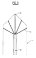
- a building of the type cathedral includes central pillars 1, 2, lateral pillars 3, 4, flying buttresses 5, 6 connecting the central pillars 1, 2 to the pillars lateral 3, 4, a central roof 7 resting on the top of the pillars central 1, 2 and side roofs 8, 9 resting on the pillars central 1, 2, and the lateral pillars 3, 4.
- the stabilization system 10 comprises a unit of control 11, sensors and actuators.
- the sensors include an anemometer / gyrometer 12 disposed at the top of the central roof 7, a seismic sensor 13 disposed in the ground under the building, and force sensors 14, 15, for example gauges of stress, arranged in the foot of the central pillars 1, 2.
- the sensors connected to the control unit 11 by electrical connections or Microwave.
- the actuators comprise subassemblies 16 and 17, 18 and 19 disposed respectively in the central pillars 1, 2 and the lateral pillars 3, 4.
- the autonomous energy control unit 11 is arranged in a technical room of the building.
- Each subassembly 16 to 19 comprises a tie rod 20, one of which end is firmly attached to one end of the pillar corresponding, and a jack 21 connected on one side to the free end of the rod and on the other side firmly secured to the other end of the pillar.
- the link pulling 20-lateral pillar 3, 4 is provided by a plate 22 which bears on a surface of the pillar perpendicular to the tie rod 20 to ensure the transmission of vertical compressive forces to the pillar.
- the plate 22 is in the high position near the top of the lateral pillars 3, 4.
- the end of the tie 20 is secured at one end bottom of the central pillar 1, 2 corresponding by sealing on a length of a few tens of centimeters in a hole drilled in the pillar for housing said tie rod. Sealing can be done at medium of a resin mortar. The end of the tie rod 20 will be provided with reliefs favoring adhesion of the mortar. The rest of the tie 20 is free in said hole.
- the tie rod 20 may be made of steel, for example stainless, based on fiberglass, carbon, or aramid, or cable, or alloy with shape memory.
- the jack 21 is secured to the other end of the pillar 1, 2 by sealing with resin mortar, or by a non-platinum represented.
- Installation of the stabilization system 10 in the building is as follows. We are cleaning up in the central pillars 1, 2 and lateral pillars 3, 4, the cavities necessary for the installation of tie rods 20, cylinders 21 and plates 22. For this purpose, drills, for example by laser guidance, a longitudinal hole of small diameter, for example 30 mm, in the central pillars 1, 2 and the lateral pillars 3, 4. digs the housing of the cylinders 21 in the foundations 3a, 4a of the lateral pillars 3, 4 and in the vertex 1b, 2b of the central pillars 1, 2. A flat surface 3b, 4b is disengaged at the top of the lateral pillars 3, 4.
- Tie rods 20 are placed in the holes of the central pillars 1, 2 and lateral pillars 3, 4.
- the jacks 21 are placed in the foundations 3a, 4a of the lateral pillars 3, 4.
- the fastening of the jack 21 and the corresponding foundation 3a, 4a is effected by direct support of a horizontal surface 21a of the cylinder 21 on a horizontal surface corresponding to the foundation 3a, 4a, or by sealing the part fixed cylinder 21, or better by sealing a flange, not shown, on which the jack 21 is fixed by a screw-nut assembly, no shown, allowing easy disassembly.
- the mortar or stone may then be resealed top of the lateral pillars 3, 4 covering the plate 22.
- the control unit 11 is installed in an accessible place of the building and is expected a power supply 23 on the sector and a backup battery and / or a pressure accumulator hydraulic or pneumatic 24.
- the control unit 11 is connected to the sensors and actuators by electrical connections or Hydraulic.
- a link to an external management center 25 through wired or wireless path is planned.
- the management center 25 is able to provide meteorological information.
- the operation of the stabilization system 10 is the next.
- the tie rods 20 are normally relaxed and the actuators 21 inactive.
- the system becomes active on detection by sensors and the control unit 11 sends the cylinders an order to retract for exert a determined stress of tension on the corresponding tie rods thus putting an additional compression stress on the pillars 1 to 4 and reducing the risk of collapse of said pillars 1 to 4.
- the order is maintained and adjusted during the necessary time period.
- the effort is determined according to the solicitations recorded, and holding the pillars in compression. For example, we can apply a force of 100 kN. We can also take into account the orientation of the wind, especially if the building offers a hold to the wind, to exercise a effort adapted to each pillar or structural element.
- the control unit 11 takes into account the direction and wind pressure by putting in compression only pillars located downwind, for example pillars 1 and 3 for a directed wind according to arrow 26. This avoids compression pillars sheltered from the wind. In case of very strong wind, we can put in high compression the pillars 1 and 3 and in medium compression the pillars 2 and 4, and more precisely according to the values obtained by a modeling of the building carried out beforehand and leading to a action in real time.
- control unit 11 It is even more interesting than the control unit 11 also take into account information gathered by the anemometer / gyrometer 12. The control unit 11 then operates in real time and the compression is better suited to the speed and the or to the instantaneous directions of the wind. The control unit 11 sends then orders at close intervals to the jacks 21. The additional compression exerted is shorter and can therefore be much stronger. Maximum additional compression admissible by the building is indeed inversely proportional to the duration during which it is exercised.
- An allowable compressive stress for an overload instantaneous of a few minutes will be about 20 to 22% higher than the permissible compressive stress for an applied overload in the short term, for example less than a week, even higher approximately 17% to the permissible compressive stress for a overload applied in the medium term, for example a week to six months, it even exceeds by about 10 to 12% the stress of permissible compression for long-term overload, for example six months to ten years, she even higher by about 17% in the permissible compressive stress for an overload permanent for more than ten years. So the compression constraint allowable for an instantaneous overload can reach around 183% of the compressive stress allowed for overload permed.
- the control unit 11 can also take into account the information provided by the seismic sensor 13 and by a center of remote seismic prediction 30 and connected to the external management center 25 to compress the building as soon as a seismic shock greater than a threshold is detected, eg exerting a force according to arrow 27 or as soon as a seismic risk is estimated.
- the control unit 11 takes into account the information provided by the force sensors 14, 15, which can be used to test the good system operation, to calibrate the behavior of the building and the load transfers between the pillars and the structural elements depending on the speed and direction of the wind.
- the unit of command 11 can then establish and store a map of necessary compressions to stabilize the building under a wind of speed x and direction a.
- the jack 21 is arranged in a housing 29 formed in the foundations 3a of the pillar 3 and presses on the upper flat surface 29a of the housing 29.
- the end of a tie rod 20 is subdivided into diverging strands 31 sealed in 32 formed holes in the ends of the lateral pillars 3,4. This reduces the work to be performed on the ends of the pillars 3,4.
- the pillar 4 is provided with two tie rods 20 mounted in X to be able to exert an effort having a component horizontal.
- the pillar 4 comprises two jacks 21 and two plates 22.
- the thrust arch 6 is also provided with a subassembly 33 comprising a tie rod 20 housed in said thrust arch 6, a plate 22 housed in the bearing 4 in the extension of the buttressing bow 6, and a cylinder 21 disposed on the pillar 2 at the other end of the tie rod 20.
- a stabilized building is obtained dynamically and economically by preserving the surfaces and volumes of historical, artistic, cultural interest, etc.
- the invention is perfectly adapted to any old or recent building and allows by its reactivity to avoid or at least reduce considerably the rate and extent of claims in the event of a storm.
Landscapes
- Engineering & Computer Science (AREA)
- Architecture (AREA)
- Business, Economics & Management (AREA)
- Emergency Management (AREA)
- Environmental & Geological Engineering (AREA)
- Civil Engineering (AREA)
- Structural Engineering (AREA)
- Buildings Adapted To Withstand Abnormal External Influences (AREA)
- Air Conditioning Control Device (AREA)
- Continuous Casting (AREA)
- Apparatuses For Generation Of Mechanical Vibrations (AREA)
- Vibration Prevention Devices (AREA)
- Vending Machines For Individual Products (AREA)
- Food Preservation Except Freezing, Refrigeration, And Drying (AREA)
Applications Claiming Priority (3)
| Application Number | Priority Date | Filing Date | Title |
|---|---|---|---|
| FR0303128 | 2003-03-13 | ||
| FR0303128A FR2852343B1 (fr) | 2003-03-13 | 2003-03-13 | Procede et systeme de stabilisation d'un edifice |
| EP04290572A EP1457622B1 (de) | 2003-03-13 | 2004-03-03 | Verfahren und Vorrichtung zum Stabilisieren eines Gebäudes |
Related Parent Applications (1)
| Application Number | Title | Priority Date | Filing Date |
|---|---|---|---|
| EP04290572A Division EP1457622B1 (de) | 2003-03-13 | 2004-03-03 | Verfahren und Vorrichtung zum Stabilisieren eines Gebäudes |
Publications (1)
| Publication Number | Publication Date |
|---|---|
| EP1564349A1 true EP1564349A1 (de) | 2005-08-17 |
Family
ID=32749791
Family Applications (2)
| Application Number | Title | Priority Date | Filing Date |
|---|---|---|---|
| EP04290572A Expired - Lifetime EP1457622B1 (de) | 2003-03-13 | 2004-03-03 | Verfahren und Vorrichtung zum Stabilisieren eines Gebäudes |
| EP05290564A Withdrawn EP1564349A1 (de) | 2003-03-13 | 2004-03-03 | Verfahren und Vorrichtung zum Stabilisieren eines Gebäudes |
Family Applications Before (1)
| Application Number | Title | Priority Date | Filing Date |
|---|---|---|---|
| EP04290572A Expired - Lifetime EP1457622B1 (de) | 2003-03-13 | 2004-03-03 | Verfahren und Vorrichtung zum Stabilisieren eines Gebäudes |
Country Status (6)
| Country | Link |
|---|---|
| EP (2) | EP1457622B1 (de) |
| AT (1) | ATE333022T1 (de) |
| DE (1) | DE602004001472T2 (de) |
| ES (1) | ES2268585T3 (de) |
| FR (1) | FR2852343B1 (de) |
| PT (1) | PT1457622E (de) |
Cited By (2)
| Publication number | Priority date | Publication date | Assignee | Title |
|---|---|---|---|---|
| WO2010097642A1 (en) * | 2009-02-25 | 2010-09-02 | Loannis Lymberis | Hydraulic tie rod for construction projects |
| US9540783B2 (en) | 2008-02-14 | 2017-01-10 | Ioannis Lymberis | Tie rod for structural projects |
Families Citing this family (1)
| Publication number | Priority date | Publication date | Assignee | Title |
|---|---|---|---|---|
| CN106979798B (zh) * | 2017-02-27 | 2019-01-25 | 皖西学院 | 一种土木工程结构健康检测系统 |
Citations (3)
| Publication number | Priority date | Publication date | Assignee | Title |
|---|---|---|---|---|
| US4956947A (en) * | 1988-04-01 | 1990-09-18 | Middleton Leonard R | Live tendon system inhibiting sway of high rise structures and method |
| US4964246A (en) * | 1988-03-07 | 1990-10-23 | Kajima Corporation | Rigidity control system for variable rigidity structure |
| US5062765A (en) * | 1990-06-25 | 1991-11-05 | Mcconachy H Reginald | High tower wind generating system |
Family Cites Families (2)
| Publication number | Priority date | Publication date | Assignee | Title |
|---|---|---|---|---|
| JPH10292665A (ja) * | 1997-04-14 | 1998-11-04 | Taisei Corp | 構造物の震動対応補強方法 |
| JP2001011939A (ja) * | 1999-07-01 | 2001-01-16 | Ikuya Toda | 建造物の倒壊防止のための補強方法 |
-
2003
- 2003-03-13 FR FR0303128A patent/FR2852343B1/fr not_active Expired - Fee Related
-
2004
- 2004-03-03 PT PT04290572T patent/PT1457622E/pt unknown
- 2004-03-03 EP EP04290572A patent/EP1457622B1/de not_active Expired - Lifetime
- 2004-03-03 DE DE602004001472T patent/DE602004001472T2/de not_active Expired - Fee Related
- 2004-03-03 AT AT04290572T patent/ATE333022T1/de not_active IP Right Cessation
- 2004-03-03 ES ES04290572T patent/ES2268585T3/es not_active Expired - Lifetime
- 2004-03-03 EP EP05290564A patent/EP1564349A1/de not_active Withdrawn
Patent Citations (3)
| Publication number | Priority date | Publication date | Assignee | Title |
|---|---|---|---|---|
| US4964246A (en) * | 1988-03-07 | 1990-10-23 | Kajima Corporation | Rigidity control system for variable rigidity structure |
| US4956947A (en) * | 1988-04-01 | 1990-09-18 | Middleton Leonard R | Live tendon system inhibiting sway of high rise structures and method |
| US5062765A (en) * | 1990-06-25 | 1991-11-05 | Mcconachy H Reginald | High tower wind generating system |
Cited By (2)
| Publication number | Priority date | Publication date | Assignee | Title |
|---|---|---|---|---|
| US9540783B2 (en) | 2008-02-14 | 2017-01-10 | Ioannis Lymberis | Tie rod for structural projects |
| WO2010097642A1 (en) * | 2009-02-25 | 2010-09-02 | Loannis Lymberis | Hydraulic tie rod for construction projects |
Also Published As
| Publication number | Publication date |
|---|---|
| FR2852343A1 (fr) | 2004-09-17 |
| DE602004001472T2 (de) | 2007-02-08 |
| EP1457622A1 (de) | 2004-09-15 |
| ATE333022T1 (de) | 2006-08-15 |
| FR2852343B1 (fr) | 2006-03-03 |
| ES2268585T3 (es) | 2007-03-16 |
| PT1457622E (pt) | 2006-12-29 |
| EP1457622B1 (de) | 2006-07-12 |
| DE602004001472D1 (de) | 2006-08-24 |
Similar Documents
| Publication | Publication Date | Title |
|---|---|---|
| KR101129692B1 (ko) | 지중변위측정장치 | |
| Hoult et al. | Long-term wireless structural health monitoring of the Ferriby Road Bridge | |
| KR101945598B1 (ko) | 조립식 교각 시스템의 급속시공을 위한 프리캐스트 피어캡과 교각기둥 상면 사이 그라우트 접합장치 및 시공방법 | |
| EP2061936A2 (de) | Gebäude, insbesondere ein wohngebäude, und verfahren zu seiner aufstellung | |
| CN113237588B (zh) | 一种考虑混凝土收缩徐变影响的支撑轴力监测方法及系统 | |
| EP1457622B1 (de) | Verfahren und Vorrichtung zum Stabilisieren eines Gebäudes | |
| Sreeshylam et al. | Condition monitoring of prestressed concrete structures using vibrating wire sensors. | |
| Faulkner et al. | Structural health monitoring systems in difficult environments—offshore wind turbines | |
| FR3009575A1 (fr) | Portion d'enveloppe de batiment pour ouvrage permanent | |
| JP2017106878A (ja) | 構造物の損傷検知方法及びシステム | |
| FR2862994A1 (fr) | Elements de structure en beton arme legers et isolants pour la construction ou la renovation d'immeubles. | |
| CN101440834A (zh) | 一种用于电力线路在线装置安装的u型螺栓组件 | |
| FR3012497A1 (fr) | Procede de renforcement d'un element de construction en bois par assemblage d'un module de renfort mis en post-tension | |
| CN117385732B (zh) | 一种预制装配式摇摆桥墩结构体系、安装方法及应用 | |
| FR2635550A1 (fr) | Procede de surelevation d'immeubles | |
| EP3299762A1 (de) | Instrumentiertes strukturelement aus beton | |
| Magne et al. | Health monitoring of the Saint-Jean bridge of Bordeaux, France using fiber Bragg grating extensometers | |
| EP2319998A1 (de) | Erdbebenresistentes Profil für ein Modul mit thermischer Trennung, und mit mindestens einem solchen Profil ausgestattetes Modul mit thermischer Trennung | |
| FR2962746A1 (fr) | Support catenaire | |
| FR2940810A1 (fr) | Toiture avec protection d'etancheite. | |
| EP3683360B1 (de) | Statischer penetrometer mit ausgelagertem komprimierbaren system, und verwendung eines solchen penetrometers | |
| JP6633928B2 (ja) | 発電システム | |
| Zhang et al. | Use of structural health monitoring for assessing historical bridges under heavy loads | |
| FR2895760A1 (fr) | Procede et dispositif d'ancrage d'un objet sur une terrasse | |
| Decker | A method of strengthening monitored deficient bridges |
Legal Events
| Date | Code | Title | Description |
|---|---|---|---|
| PUAI | Public reference made under article 153(3) epc to a published international application that has entered the european phase |
Free format text: ORIGINAL CODE: 0009012 |
|
| AC | Divisional application: reference to earlier application |
Ref document number: 1457622 Country of ref document: EP Kind code of ref document: P |
|
| AK | Designated contracting states |
Kind code of ref document: A1 Designated state(s): AT BE BG CH CY CZ DE DK EE ES FI FR GB GR HU IE IT LI LU MC NL PL PT RO SE SI SK TR |
|
| AX | Request for extension of the european patent |
Extension state: AL LV MK |
|
| 17P | Request for examination filed |
Effective date: 20060206 |
|
| AKX | Designation fees paid |
Designated state(s): AT BE BG CH CY CZ DE DK EE ES FI FR GB GR HU IE IT LI LU MC NL PL PT RO SE SI SK TR |
|
| 17Q | First examination report despatched |
Effective date: 20060726 |
|
| GRAP | Despatch of communication of intention to grant a patent |
Free format text: ORIGINAL CODE: EPIDOSNIGR1 |
|
| STAA | Information on the status of an ep patent application or granted ep patent |
Free format text: STATUS: THE APPLICATION IS DEEMED TO BE WITHDRAWN |
|
| 18D | Application deemed to be withdrawn |
Effective date: 20070907 |