EP1564251B1 - Polythiophene compositions for improving organic light-emitting diodes - Google Patents
Polythiophene compositions for improving organic light-emitting diodes Download PDFInfo
- Publication number
- EP1564251B1 EP1564251B1 EP05002012A EP05002012A EP1564251B1 EP 1564251 B1 EP1564251 B1 EP 1564251B1 EP 05002012 A EP05002012 A EP 05002012A EP 05002012 A EP05002012 A EP 05002012A EP 1564251 B1 EP1564251 B1 EP 1564251B1
- Authority
- EP
- European Patent Office
- Prior art keywords
- hole
- polymer
- coo
- layer
- formulation according
- Prior art date
- Legal status (The legal status is an assumption and is not a legal conclusion. Google has not performed a legal analysis and makes no representation as to the accuracy of the status listed.)
- Not-in-force
Links
- 239000000203 mixture Substances 0.000 title claims abstract description 90
- 229920000123 polythiophene Polymers 0.000 title claims abstract description 37
- 229920000642 polymer Polymers 0.000 claims abstract description 48
- -1 carboxylate salt Chemical class 0.000 claims abstract description 44
- 239000000758 substrate Substances 0.000 claims abstract description 36
- 238000009472 formulation Methods 0.000 claims description 62
- 229920000172 poly(styrenesulfonic acid) Polymers 0.000 claims description 29
- 229940005642 polystyrene sulfonic acid Drugs 0.000 claims description 28
- KFZMGEQAYNKOFK-UHFFFAOYSA-N Isopropanol Chemical compound CC(C)O KFZMGEQAYNKOFK-UHFFFAOYSA-N 0.000 claims description 27
- LFQSCWFLJHTTHZ-UHFFFAOYSA-N Ethanol Chemical compound CCO LFQSCWFLJHTTHZ-UHFFFAOYSA-N 0.000 claims description 23
- 239000003085 diluting agent Substances 0.000 claims description 22
- OKKJLVBELUTLKV-UHFFFAOYSA-N Methanol Chemical compound OC OKKJLVBELUTLKV-UHFFFAOYSA-N 0.000 claims description 21
- LRHPLDYGYMQRHN-UHFFFAOYSA-N N-Butanol Chemical compound CCCCO LRHPLDYGYMQRHN-UHFFFAOYSA-N 0.000 claims description 14
- BDERNNFJNOPAEC-UHFFFAOYSA-N propan-1-ol Chemical compound CCCO BDERNNFJNOPAEC-UHFFFAOYSA-N 0.000 claims description 14
- XLYOFNOQVPJJNP-UHFFFAOYSA-N water Substances O XLYOFNOQVPJJNP-UHFFFAOYSA-N 0.000 claims description 11
- 238000004519 manufacturing process Methods 0.000 claims description 9
- RTZKZFJDLAIYFH-UHFFFAOYSA-N Diethyl ether Chemical compound CCOCC RTZKZFJDLAIYFH-UHFFFAOYSA-N 0.000 claims description 8
- 239000002253 acid Substances 0.000 claims description 5
- 229920001577 copolymer Polymers 0.000 claims description 5
- 238000000576 coating method Methods 0.000 claims description 4
- RRZIJNVZMJUGTK-UHFFFAOYSA-N 1,1,2-trifluoro-2-(1,2,2-trifluoroethenoxy)ethene Chemical compound FC(F)=C(F)OC(F)=C(F)F RRZIJNVZMJUGTK-UHFFFAOYSA-N 0.000 claims description 3
- 150000003254 radicals Chemical class 0.000 claims description 3
- BFKJFAAPBSQJPD-UHFFFAOYSA-N tetrafluoroethene Chemical group FC(F)=C(F)F BFKJFAAPBSQJPD-UHFFFAOYSA-N 0.000 claims description 3
- VGGSQFUCUMXWEO-UHFFFAOYSA-N Ethene Chemical class C=C VGGSQFUCUMXWEO-UHFFFAOYSA-N 0.000 claims description 2
- 239000005977 Ethylene Substances 0.000 claims description 2
- 230000005669 field effect Effects 0.000 claims description 2
- TUJKJAMUKRIRHC-UHFFFAOYSA-N hydroxyl Chemical compound [OH] TUJKJAMUKRIRHC-UHFFFAOYSA-N 0.000 claims description 2
- QQONPFPTGQHPMA-UHFFFAOYSA-N propylene Natural products CC=C QQONPFPTGQHPMA-UHFFFAOYSA-N 0.000 claims description 2
- 239000010409 thin film Substances 0.000 claims description 2
- 125000005915 C6-C14 aryl group Chemical group 0.000 claims 1
- 125000003118 aryl group Chemical group 0.000 abstract description 3
- 125000000217 alkyl group Chemical group 0.000 abstract description 2
- 125000002947 alkylene group Chemical group 0.000 abstract description 2
- 229920002313 fluoropolymer Polymers 0.000 abstract 2
- 150000008054 sulfonate salts Chemical class 0.000 abstract 2
- 125000003710 aryl alkyl group Chemical group 0.000 abstract 1
- 229910052792 caesium Inorganic materials 0.000 abstract 1
- 229910052739 hydrogen Inorganic materials 0.000 abstract 1
- 125000002887 hydroxy group Chemical group [H]O* 0.000 abstract 1
- 125000002768 hydroxyalkyl group Chemical group 0.000 abstract 1
- 229910052744 lithium Inorganic materials 0.000 abstract 1
- 229910052700 potassium Inorganic materials 0.000 abstract 1
- 229910052701 rubidium Inorganic materials 0.000 abstract 1
- 229910052708 sodium Inorganic materials 0.000 abstract 1
- 239000010410 layer Substances 0.000 description 79
- 239000000243 solution Substances 0.000 description 27
- 229920001609 Poly(3,4-ethylenedioxythiophene) Polymers 0.000 description 24
- 238000000034 method Methods 0.000 description 18
- 229910052751 metal Inorganic materials 0.000 description 16
- 239000002184 metal Substances 0.000 description 16
- 239000000463 material Substances 0.000 description 13
- IAZDPXIOMUYVGZ-UHFFFAOYSA-N Dimethylsulphoxide Chemical compound CS(C)=O IAZDPXIOMUYVGZ-UHFFFAOYSA-N 0.000 description 12
- ZMXDDKWLCZADIW-UHFFFAOYSA-N N,N-Dimethylformamide Chemical compound CN(C)C=O ZMXDDKWLCZADIW-UHFFFAOYSA-N 0.000 description 12
- WYURNTSHIVDZCO-UHFFFAOYSA-N Tetrahydrofuran Chemical compound C1CCOC1 WYURNTSHIVDZCO-UHFFFAOYSA-N 0.000 description 12
- 229920000557 Nafion® Polymers 0.000 description 10
- 239000002904 solvent Substances 0.000 description 10
- ZWEHNKRNPOVVGH-UHFFFAOYSA-N 2-Butanone Chemical compound CCC(C)=O ZWEHNKRNPOVVGH-UHFFFAOYSA-N 0.000 description 9
- WEVYAHXRMPXWCK-UHFFFAOYSA-N Acetonitrile Chemical compound CC#N WEVYAHXRMPXWCK-UHFFFAOYSA-N 0.000 description 9
- LYCAIKOWRPUZTN-UHFFFAOYSA-N Ethylene glycol Chemical compound OCCO LYCAIKOWRPUZTN-UHFFFAOYSA-N 0.000 description 9
- PEDCQBHIVMGVHV-UHFFFAOYSA-N Glycerine Chemical compound OCC(O)CO PEDCQBHIVMGVHV-UHFFFAOYSA-N 0.000 description 9
- 239000006185 dispersion Substances 0.000 description 9
- 238000002360 preparation method Methods 0.000 description 9
- 230000000052 comparative effect Effects 0.000 description 8
- 150000001298 alcohols Chemical class 0.000 description 7
- CSCPPACGZOOCGX-UHFFFAOYSA-N Acetone Chemical compound CC(C)=O CSCPPACGZOOCGX-UHFFFAOYSA-N 0.000 description 6
- SECXISVLQFMRJM-UHFFFAOYSA-N N-Methylpyrrolidone Chemical compound CN1CCCC1=O SECXISVLQFMRJM-UHFFFAOYSA-N 0.000 description 6
- 229920001940 conductive polymer Polymers 0.000 description 6
- SWXVUIWOUIDPGS-UHFFFAOYSA-N diacetone alcohol Chemical compound CC(=O)CC(C)(C)O SWXVUIWOUIDPGS-UHFFFAOYSA-N 0.000 description 6
- 239000011521 glass Substances 0.000 description 6
- 239000010414 supernatant solution Substances 0.000 description 6
- YLQBMQCUIZJEEH-UHFFFAOYSA-N tetrahydrofuran Natural products C=1C=COC=1 YLQBMQCUIZJEEH-UHFFFAOYSA-N 0.000 description 6
- 239000010408 film Substances 0.000 description 5
- 238000002347 injection Methods 0.000 description 5
- 239000007924 injection Substances 0.000 description 5
- 239000007800 oxidant agent Substances 0.000 description 5
- GJVFBWCTGUSGDD-UHFFFAOYSA-L pentamethonium bromide Chemical compound [Br-].[Br-].C[N+](C)(C)CCCCC[N+](C)(C)C GJVFBWCTGUSGDD-UHFFFAOYSA-L 0.000 description 5
- 239000002798 polar solvent Substances 0.000 description 5
- 229920000767 polyaniline Polymers 0.000 description 5
- 229920000128 polypyrrole Polymers 0.000 description 5
- 238000007740 vapor deposition Methods 0.000 description 5
- 239000002318 adhesion promoter Substances 0.000 description 4
- 239000011230 binding agent Substances 0.000 description 4
- 238000006243 chemical reaction Methods 0.000 description 4
- 239000004020 conductor Substances 0.000 description 4
- 238000005259 measurement Methods 0.000 description 4
- 239000007787 solid Substances 0.000 description 4
- 150000003462 sulfoxides Chemical class 0.000 description 4
- 239000004094 surface-active agent Substances 0.000 description 4
- FXHOOIRPVKKKFG-UHFFFAOYSA-N N,N-Dimethylacetamide Chemical compound CN(C)C(C)=O FXHOOIRPVKKKFG-UHFFFAOYSA-N 0.000 description 3
- XLOMVQKBTHCTTD-UHFFFAOYSA-N Zinc monoxide Chemical compound [Zn]=O XLOMVQKBTHCTTD-UHFFFAOYSA-N 0.000 description 3
- 150000008431 aliphatic amides Chemical class 0.000 description 3
- 239000003795 chemical substances by application Substances 0.000 description 3
- 150000001875 compounds Chemical class 0.000 description 3
- 239000003431 cross linking reagent Substances 0.000 description 3
- 150000003950 cyclic amides Chemical class 0.000 description 3
- 239000007772 electrode material Substances 0.000 description 3
- 238000005401 electroluminescence Methods 0.000 description 3
- 238000005538 encapsulation Methods 0.000 description 3
- 150000002170 ethers Chemical class 0.000 description 3
- AMGQUBHHOARCQH-UHFFFAOYSA-N indium;oxotin Chemical compound [In].[Sn]=O AMGQUBHHOARCQH-UHFFFAOYSA-N 0.000 description 3
- 150000002500 ions Chemical class 0.000 description 3
- 125000002496 methyl group Chemical group [H]C([H])([H])* 0.000 description 3
- 229920002098 polyfluorene Polymers 0.000 description 3
- CMSGUKVDXXTJDQ-UHFFFAOYSA-N 4-(2-naphthalen-1-ylethylamino)-4-oxobutanoic acid Chemical compound C1=CC=C2C(CCNC(=O)CCC(=O)O)=CC=CC2=C1 CMSGUKVDXXTJDQ-UHFFFAOYSA-N 0.000 description 2
- QGZKDVFQNNGYKY-UHFFFAOYSA-N Ammonia Chemical compound N QGZKDVFQNNGYKY-UHFFFAOYSA-N 0.000 description 2
- 229920000089 Cyclic olefin copolymer Polymers 0.000 description 2
- 239000004713 Cyclic olefin copolymer Substances 0.000 description 2
- VTLYFUHAOXGGBS-UHFFFAOYSA-N Fe3+ Chemical class [Fe+3] VTLYFUHAOXGGBS-UHFFFAOYSA-N 0.000 description 2
- CTQNGGLPUBDAKN-UHFFFAOYSA-N O-Xylene Chemical compound CC1=CC=CC=C1C CTQNGGLPUBDAKN-UHFFFAOYSA-N 0.000 description 2
- 229920002125 Sokalan® Polymers 0.000 description 2
- PPBRXRYQALVLMV-UHFFFAOYSA-N Styrene Chemical compound C=CC1=CC=CC=C1 PPBRXRYQALVLMV-UHFFFAOYSA-N 0.000 description 2
- 150000007513 acids Chemical class 0.000 description 2
- 229910052783 alkali metal Inorganic materials 0.000 description 2
- 239000002585 base Substances 0.000 description 2
- 229910052802 copper Inorganic materials 0.000 description 2
- 125000000753 cycloalkyl group Chemical group 0.000 description 2
- 238000004821 distillation Methods 0.000 description 2
- PGFXOWRDDHCDTE-UHFFFAOYSA-N hexafluoropropylene oxide Chemical compound FC(F)(F)C1(F)OC1(F)F PGFXOWRDDHCDTE-UHFFFAOYSA-N 0.000 description 2
- 239000012535 impurity Substances 0.000 description 2
- 230000007774 longterm Effects 0.000 description 2
- 229910044991 metal oxide Inorganic materials 0.000 description 2
- 150000004706 metal oxides Chemical class 0.000 description 2
- 229920003023 plastic Polymers 0.000 description 2
- 239000004033 plastic Substances 0.000 description 2
- 229910052697 platinum Inorganic materials 0.000 description 2
- 229920000139 polyethylene terephthalate Polymers 0.000 description 2
- 239000005020 polyethylene terephthalate Substances 0.000 description 2
- 238000006116 polymerization reaction Methods 0.000 description 2
- 238000007639 printing Methods 0.000 description 2
- 150000004756 silanes Chemical class 0.000 description 2
- 229910052709 silver Inorganic materials 0.000 description 2
- 239000000126 substance Substances 0.000 description 2
- XOLBLPGZBRYERU-UHFFFAOYSA-N tin dioxide Chemical compound O=[Sn]=O XOLBLPGZBRYERU-UHFFFAOYSA-N 0.000 description 2
- 229910001887 tin oxide Inorganic materials 0.000 description 2
- 239000012780 transparent material Substances 0.000 description 2
- NLVXSWCKKBEXTG-UHFFFAOYSA-N vinylsulfonic acid Chemical class OS(=O)(=O)C=C NLVXSWCKKBEXTG-UHFFFAOYSA-N 0.000 description 2
- 239000008096 xylene Substances 0.000 description 2
- NWUYHJFMYQTDRP-UHFFFAOYSA-N 1,2-bis(ethenyl)benzene;1-ethenyl-2-ethylbenzene;styrene Chemical class C=CC1=CC=CC=C1.CCC1=CC=CC=C1C=C.C=CC1=CC=CC=C1C=C NWUYHJFMYQTDRP-UHFFFAOYSA-N 0.000 description 1
- VXNZUUAINFGPBY-UHFFFAOYSA-N 1-Butene Chemical group CCC=C VXNZUUAINFGPBY-UHFFFAOYSA-N 0.000 description 1
- 125000004493 2-methylbut-1-yl group Chemical group CC(C*)CC 0.000 description 1
- VQGHOUODWALEFC-UHFFFAOYSA-N 2-phenylpyridine Chemical compound C1=CC=CC=C1C1=CC=CC=N1 VQGHOUODWALEFC-UHFFFAOYSA-N 0.000 description 1
- YJQSEUFVWQCHCP-UHFFFAOYSA-N 3,4-dihydroxythiophene-2,5-dicarboxylic acid Chemical class OC(=O)C=1SC(C(O)=O)=C(O)C=1O YJQSEUFVWQCHCP-UHFFFAOYSA-N 0.000 description 1
- 125000003542 3-methylbutan-2-yl group Chemical group [H]C([H])([H])C([H])(*)C([H])(C([H])([H])[H])C([H])([H])[H] 0.000 description 1
- UQRONKZLYKUEMO-UHFFFAOYSA-N 4-methyl-1-(2,4,6-trimethylphenyl)pent-4-en-2-one Chemical group CC(=C)CC(=O)Cc1c(C)cc(C)cc1C UQRONKZLYKUEMO-UHFFFAOYSA-N 0.000 description 1
- KXDHJXZQYSOELW-UHFFFAOYSA-N Carbamic acid Chemical group NC(O)=O KXDHJXZQYSOELW-UHFFFAOYSA-N 0.000 description 1
- BWGNESOTFCXPMA-UHFFFAOYSA-N Dihydrogen disulfide Chemical compound SS BWGNESOTFCXPMA-UHFFFAOYSA-N 0.000 description 1
- 229930194542 Keto Natural products 0.000 description 1
- CBENFWSGALASAD-UHFFFAOYSA-N Ozone Chemical compound [O-][O+]=O CBENFWSGALASAD-UHFFFAOYSA-N 0.000 description 1
- 229920012266 Poly(ether sulfone) PES Polymers 0.000 description 1
- 229920002845 Poly(methacrylic acid) Polymers 0.000 description 1
- 239000004695 Polyether sulfone Substances 0.000 description 1
- 239000004698 Polyethylene Substances 0.000 description 1
- 239000004642 Polyimide Substances 0.000 description 1
- 239000004743 Polypropylene Substances 0.000 description 1
- 239000007983 Tris buffer Substances 0.000 description 1
- 239000006096 absorbing agent Substances 0.000 description 1
- 125000005396 acrylic acid ester group Chemical group 0.000 description 1
- 150000001299 aldehydes Chemical class 0.000 description 1
- 150000001338 aliphatic hydrocarbons Chemical class 0.000 description 1
- 239000003513 alkali Substances 0.000 description 1
- 150000001340 alkali metals Chemical class 0.000 description 1
- 150000001447 alkali salts Chemical class 0.000 description 1
- 150000001343 alkyl silanes Chemical class 0.000 description 1
- 125000005530 alkylenedioxy group Chemical group 0.000 description 1
- IYABWNGZIDDRAK-UHFFFAOYSA-N allene Chemical group C=C=C IYABWNGZIDDRAK-UHFFFAOYSA-N 0.000 description 1
- AZDRQVAHHNSJOQ-UHFFFAOYSA-N alumane Chemical class [AlH3] AZDRQVAHHNSJOQ-UHFFFAOYSA-N 0.000 description 1
- 229910052782 aluminium Inorganic materials 0.000 description 1
- XAGFODPZIPBFFR-UHFFFAOYSA-N aluminium Chemical compound [Al] XAGFODPZIPBFFR-UHFFFAOYSA-N 0.000 description 1
- 150000004945 aromatic hydrocarbons Chemical class 0.000 description 1
- 125000001797 benzyl group Chemical group [H]C1=C([H])C([H])=C(C([H])=C1[H])C([H])([H])* 0.000 description 1
- 229910052794 bromium Inorganic materials 0.000 description 1
- 238000004364 calculation method Methods 0.000 description 1
- 150000001733 carboxylic acid esters Chemical class 0.000 description 1
- 150000001735 carboxylic acids Chemical class 0.000 description 1
- 238000005266 casting Methods 0.000 description 1
- 238000012512 characterization method Methods 0.000 description 1
- 229910052801 chlorine Inorganic materials 0.000 description 1
- 238000004140 cleaning Methods 0.000 description 1
- 239000011248 coating agent Substances 0.000 description 1
- 239000002322 conducting polymer Substances 0.000 description 1
- 229920000547 conjugated polymer Polymers 0.000 description 1
- 238000005260 corrosion Methods 0.000 description 1
- 230000007797 corrosion Effects 0.000 description 1
- 238000007766 curtain coating Methods 0.000 description 1
- 125000004093 cyano group Chemical group *C#N 0.000 description 1
- 125000004122 cyclic group Chemical group 0.000 description 1
- 125000000582 cycloheptyl group Chemical group [H]C1([H])C([H])([H])C([H])([H])C([H])([H])C([H])(*)C([H])([H])C1([H])[H] 0.000 description 1
- 125000000113 cyclohexyl group Chemical group [H]C1([H])C([H])([H])C([H])([H])C([H])(*)C([H])([H])C1([H])[H] 0.000 description 1
- 125000006547 cyclononyl group Chemical group [H]C1([H])C([H])([H])C([H])([H])C([H])([H])C([H])([H])C([H])(*)C([H])([H])C([H])([H])C1([H])[H] 0.000 description 1
- 125000000640 cyclooctyl group Chemical group [H]C1([H])C([H])([H])C([H])([H])C([H])([H])C([H])(*)C([H])([H])C([H])([H])C1([H])[H] 0.000 description 1
- 125000001511 cyclopentyl group Chemical group [H]C1([H])C([H])([H])C([H])([H])C([H])(*)C1([H])[H] 0.000 description 1
- 238000006114 decarboxylation reaction Methods 0.000 description 1
- 238000001514 detection method Methods 0.000 description 1
- 239000012153 distilled water Substances 0.000 description 1
- 238000001035 drying Methods 0.000 description 1
- 238000005516 engineering process Methods 0.000 description 1
- 229920006332 epoxy adhesive Polymers 0.000 description 1
- QUPDWYMUPZLYJZ-UHFFFAOYSA-N ethyl Chemical compound C[CH2] QUPDWYMUPZLYJZ-UHFFFAOYSA-N 0.000 description 1
- 125000001495 ethyl group Chemical group [H]C([H])([H])C([H])([H])* 0.000 description 1
- 239000007850 fluorescent dye Substances 0.000 description 1
- 229910052737 gold Inorganic materials 0.000 description 1
- 229910052736 halogen Inorganic materials 0.000 description 1
- 150000002367 halogens Chemical class 0.000 description 1
- 230000005660 hydrophilic surface Effects 0.000 description 1
- 125000004029 hydroxymethyl group Chemical group [H]OC([H])([H])* 0.000 description 1
- 239000011261 inert gas Substances 0.000 description 1
- 239000011229 interlayer Substances 0.000 description 1
- 229910052740 iodine Inorganic materials 0.000 description 1
- 125000000959 isobutyl group Chemical group [H]C([H])([H])C([H])(C([H])([H])[H])C([H])([H])* 0.000 description 1
- 125000001972 isopentyl group Chemical group [H]C([H])([H])C([H])(C([H])([H])[H])C([H])([H])C([H])([H])* 0.000 description 1
- 125000001449 isopropyl group Chemical group [H]C([H])([H])C([H])(*)C([H])([H])[H] 0.000 description 1
- 125000000468 ketone group Chemical group 0.000 description 1
- 150000003951 lactams Chemical class 0.000 description 1
- 239000002346 layers by function Substances 0.000 description 1
- 229920002521 macromolecule Polymers 0.000 description 1
- 239000011976 maleic acid Substances 0.000 description 1
- 239000011159 matrix material Substances 0.000 description 1
- 150000002739 metals Chemical class 0.000 description 1
- 239000000178 monomer Substances 0.000 description 1
- 125000004108 n-butyl group Chemical group [H]C([H])([H])C([H])([H])C([H])([H])C([H])([H])* 0.000 description 1
- 125000003136 n-heptyl group Chemical group [H]C([H])([H])C([H])([H])C([H])([H])C([H])([H])C([H])([H])C([H])([H])C([H])([H])* 0.000 description 1
- 125000001280 n-hexyl group Chemical group C(CCCCC)* 0.000 description 1
- 125000000740 n-pentyl group Chemical group [H]C([H])([H])C([H])([H])C([H])([H])C([H])([H])C([H])([H])* 0.000 description 1
- 125000004123 n-propyl group Chemical group [H]C([H])([H])C([H])([H])C([H])([H])* 0.000 description 1
- 125000001624 naphthyl group Chemical group 0.000 description 1
- 125000001971 neopentyl group Chemical group [H]C([*])([H])C(C([H])([H])[H])(C([H])([H])[H])C([H])([H])[H] 0.000 description 1
- 239000012299 nitrogen atmosphere Substances 0.000 description 1
- 239000012044 organic layer Substances 0.000 description 1
- 239000011368 organic material Substances 0.000 description 1
- 239000003960 organic solvent Substances 0.000 description 1
- 125000001037 p-tolyl group Chemical group [H]C1=C([H])C(=C([H])C([H])=C1*)C([H])([H])[H] 0.000 description 1
- 239000002245 particle Substances 0.000 description 1
- 125000003538 pentan-3-yl group Chemical group [H]C([H])([H])C([H])([H])C([H])(*)C([H])([H])C([H])([H])[H] 0.000 description 1
- 125000001997 phenyl group Chemical group [H]C1=C([H])C([H])=C(*)C([H])=C1[H] 0.000 description 1
- 229920002120 photoresistant polymer Polymers 0.000 description 1
- 229920006255 plastic film Polymers 0.000 description 1
- 239000002985 plastic film Substances 0.000 description 1
- 229920003227 poly(N-vinyl carbazole) Polymers 0.000 description 1
- 229920000553 poly(phenylenevinylene) Polymers 0.000 description 1
- 229920002492 poly(sulfone) Polymers 0.000 description 1
- 229920000058 polyacrylate Polymers 0.000 description 1
- 229920000515 polycarbonate Polymers 0.000 description 1
- 239000004417 polycarbonate Substances 0.000 description 1
- 229920006289 polycarbonate film Polymers 0.000 description 1
- 229920000728 polyester Polymers 0.000 description 1
- 229920006267 polyester film Polymers 0.000 description 1
- 229920006393 polyether sulfone Polymers 0.000 description 1
- 229920000573 polyethylene Polymers 0.000 description 1
- 229920001721 polyimide Polymers 0.000 description 1
- 229920001444 polymaleic acid Polymers 0.000 description 1
- 229920000307 polymer substrate Polymers 0.000 description 1
- 229920000098 polyolefin Polymers 0.000 description 1
- 229920001155 polypropylene Polymers 0.000 description 1
- 125000002924 primary amino group Chemical group [H]N([H])* 0.000 description 1
- 239000000047 product Substances 0.000 description 1
- 150000003839 salts Chemical class 0.000 description 1
- 238000001275 scanning Auger electron spectroscopy Methods 0.000 description 1
- 125000002914 sec-butyl group Chemical group [H]C([H])([H])C([H])([H])C([H])(*)C([H])([H])[H] 0.000 description 1
- 125000003548 sec-pentyl group Chemical group [H]C([H])([H])C([H])([H])C([H])([H])C([H])(*)C([H])([H])[H] 0.000 description 1
- 239000004065 semiconductor Substances 0.000 description 1
- 150000003384 small molecules Chemical class 0.000 description 1
- 239000011877 solvent mixture Substances 0.000 description 1
- 238000004528 spin coating Methods 0.000 description 1
- 238000009987 spinning Methods 0.000 description 1
- 239000007858 starting material Substances 0.000 description 1
- 150000003440 styrenes Chemical class 0.000 description 1
- 125000001424 substituent group Chemical group 0.000 description 1
- 238000006467 substitution reaction Methods 0.000 description 1
- 150000003457 sulfones Chemical class 0.000 description 1
- 150000003460 sulfonic acids Chemical class 0.000 description 1
- 238000010345 tape casting Methods 0.000 description 1
- 125000000999 tert-butyl group Chemical group [H]C([H])([H])C(*)(C([H])([H])[H])C([H])([H])[H] 0.000 description 1
- 125000001973 tert-pentyl group Chemical group [H]C([H])([H])C([H])([H])C(*)(C([H])([H])[H])C([H])([H])[H] 0.000 description 1
- 125000000101 thioether group Chemical group 0.000 description 1
- YCGAZNXXGKTASZ-UHFFFAOYSA-N thiophene-2,5-dicarboxylic acid Chemical class OC(=O)C1=CC=C(C(O)=O)S1 YCGAZNXXGKTASZ-UHFFFAOYSA-N 0.000 description 1
- 230000036962 time dependent Effects 0.000 description 1
- BPSIOYPQMFLKFR-UHFFFAOYSA-N trimethoxy-[3-(oxiran-2-ylmethoxy)propyl]silane Chemical compound CO[Si](OC)(OC)CCCOCC1CO1 BPSIOYPQMFLKFR-UHFFFAOYSA-N 0.000 description 1
- 238000000108 ultra-filtration Methods 0.000 description 1
- 239000011787 zinc oxide Substances 0.000 description 1
Classifications
-
- B—PERFORMING OPERATIONS; TRANSPORTING
- B60—VEHICLES IN GENERAL
- B60R—VEHICLES, VEHICLE FITTINGS, OR VEHICLE PARTS, NOT OTHERWISE PROVIDED FOR
- B60R16/00—Electric or fluid circuits specially adapted for vehicles and not otherwise provided for; Arrangement of elements of electric or fluid circuits specially adapted for vehicles and not otherwise provided for
- B60R16/02—Electric or fluid circuits specially adapted for vehicles and not otherwise provided for; Arrangement of elements of electric or fluid circuits specially adapted for vehicles and not otherwise provided for electric constitutive elements
- B60R16/0207—Wire harnesses
- B60R16/0215—Protecting, fastening and routing means therefor
-
- C—CHEMISTRY; METALLURGY
- C08—ORGANIC MACROMOLECULAR COMPOUNDS; THEIR PREPARATION OR CHEMICAL WORKING-UP; COMPOSITIONS BASED THEREON
- C08L—COMPOSITIONS OF MACROMOLECULAR COMPOUNDS
- C08L65/00—Compositions of macromolecular compounds obtained by reactions forming a carbon-to-carbon link in the main chain; Compositions of derivatives of such polymers
-
- H—ELECTRICITY
- H02—GENERATION; CONVERSION OR DISTRIBUTION OF ELECTRIC POWER
- H02G—INSTALLATION OF ELECTRIC CABLES OR LINES, OR OF COMBINED OPTICAL AND ELECTRIC CABLES OR LINES
- H02G3/00—Installations of electric cables or lines or protective tubing therefor in or on buildings, equivalent structures or vehicles
- H02G3/30—Installations of cables or lines on walls, floors or ceilings
-
- H—ELECTRICITY
- H10—SEMICONDUCTOR DEVICES; ELECTRIC SOLID-STATE DEVICES NOT OTHERWISE PROVIDED FOR
- H10K—ORGANIC ELECTRIC SOLID-STATE DEVICES
- H10K85/00—Organic materials used in the body or electrodes of devices covered by this subclass
- H10K85/10—Organic polymers or oligomers
- H10K85/111—Organic polymers or oligomers comprising aromatic, heteroaromatic, or aryl chains, e.g. polyaniline, polyphenylene or polyphenylene vinylene
- H10K85/113—Heteroaromatic compounds comprising sulfur or selene, e.g. polythiophene
- H10K85/1135—Polyethylene dioxythiophene [PEDOT]; Derivatives thereof
-
- C—CHEMISTRY; METALLURGY
- C08—ORGANIC MACROMOLECULAR COMPOUNDS; THEIR PREPARATION OR CHEMICAL WORKING-UP; COMPOSITIONS BASED THEREON
- C08L—COMPOSITIONS OF MACROMOLECULAR COMPOUNDS
- C08L25/00—Compositions of, homopolymers or copolymers of compounds having one or more unsaturated aliphatic radicals, each having only one carbon-to-carbon double bond, and at least one being terminated by an aromatic carbocyclic ring; Compositions of derivatives of such polymers
- C08L25/18—Homopolymers or copolymers of aromatic monomers containing elements other than carbon and hydrogen
-
- C—CHEMISTRY; METALLURGY
- C08—ORGANIC MACROMOLECULAR COMPOUNDS; THEIR PREPARATION OR CHEMICAL WORKING-UP; COMPOSITIONS BASED THEREON
- C08L—COMPOSITIONS OF MACROMOLECULAR COMPOUNDS
- C08L27/00—Compositions of homopolymers or copolymers of compounds having one or more unsaturated aliphatic radicals, each having only one carbon-to-carbon double bond, and at least one being terminated by a halogen; Compositions of derivatives of such polymers
- C08L27/02—Compositions of homopolymers or copolymers of compounds having one or more unsaturated aliphatic radicals, each having only one carbon-to-carbon double bond, and at least one being terminated by a halogen; Compositions of derivatives of such polymers not modified by chemical after-treatment
- C08L27/12—Compositions of homopolymers or copolymers of compounds having one or more unsaturated aliphatic radicals, each having only one carbon-to-carbon double bond, and at least one being terminated by a halogen; Compositions of derivatives of such polymers not modified by chemical after-treatment containing fluorine atoms
-
- H—ELECTRICITY
- H10—SEMICONDUCTOR DEVICES; ELECTRIC SOLID-STATE DEVICES NOT OTHERWISE PROVIDED FOR
- H10K—ORGANIC ELECTRIC SOLID-STATE DEVICES
- H10K50/00—Organic light-emitting devices
- H10K50/10—OLEDs or polymer light-emitting diodes [PLED]
- H10K50/17—Carrier injection layers
-
- Y—GENERAL TAGGING OF NEW TECHNOLOGICAL DEVELOPMENTS; GENERAL TAGGING OF CROSS-SECTIONAL TECHNOLOGIES SPANNING OVER SEVERAL SECTIONS OF THE IPC; TECHNICAL SUBJECTS COVERED BY FORMER USPC CROSS-REFERENCE ART COLLECTIONS [XRACs] AND DIGESTS
- Y02—TECHNOLOGIES OR APPLICATIONS FOR MITIGATION OR ADAPTATION AGAINST CLIMATE CHANGE
- Y02E—REDUCTION OF GREENHOUSE GAS [GHG] EMISSIONS, RELATED TO ENERGY GENERATION, TRANSMISSION OR DISTRIBUTION
- Y02E10/00—Energy generation through renewable energy sources
- Y02E10/50—Photovoltaic [PV] energy
- Y02E10/549—Organic PV cells
-
- Y—GENERAL TAGGING OF NEW TECHNOLOGICAL DEVELOPMENTS; GENERAL TAGGING OF CROSS-SECTIONAL TECHNOLOGIES SPANNING OVER SEVERAL SECTIONS OF THE IPC; TECHNICAL SUBJECTS COVERED BY FORMER USPC CROSS-REFERENCE ART COLLECTIONS [XRACs] AND DIGESTS
- Y02—TECHNOLOGIES OR APPLICATIONS FOR MITIGATION OR ADAPTATION AGAINST CLIMATE CHANGE
- Y02P—CLIMATE CHANGE MITIGATION TECHNOLOGIES IN THE PRODUCTION OR PROCESSING OF GOODS
- Y02P70/00—Climate change mitigation technologies in the production process for final industrial or consumer products
- Y02P70/50—Manufacturing or production processes characterised by the final manufactured product
Definitions
- the invention relates to formulations containing polythiophenes and other polymers, their use and electroluminescent arrangements containing hole-injecting layers containing these formulations.
- An electroluminescent (EL) device is characterized in that it emits light when current is applied when an electrical voltage is applied. Such arrangements have long been known as “light emitting diodes” (LEDs). The emission of light is due to the fact that positive charges (holes, holes) and negative charges (electrons, electrons) recombine with the emission of light.
- the LEDs commonly used in the art are all predominantly inorganic semiconductor materials.
- EL devices are known whose essential components are organic materials.
- organic EL devices typically contain one or more layers of organic charge transport compounds.
- an EL device consists of two electrodes, between which there is an organic layer that fulfills all functions, including the emission of light.
- the object of the present invention was therefore to find and provide suitable formulations for producing such EL devices. Another object was to fabricate improved EL devices from these materials.
- the general formula (I) is to be understood as meaning that the substituent R may be bonded x times to the alkylene radical A.
- formulation is any mixture of components A), B) and C) as a solid, solution or dispersion.
- polythiophene A it is also possible to use other known conductive polymers A), in particular optionally substituted ones Polyanilines or polypyrroles. These various conductive polymers can be used alone or in any mixture.
- Alkyl preferably C 1 -C 20 -alkyl, cycloalkyl, preferably C 3 -C 20 -cycloalkyl, aryl, preferably C 5 -C 14 -aryl, halogen, preferably Cl, Br, I, ether , Thioether-, disulfide, sulfoxide, sulfone, amino, aldehyde, keto, carboxylic acid ester, cyano, alkylsilane and alkoxysilane and carboxylamide groups to understand.
- At least one polythiophene containing repeating units of the general formula (I) is one containing repeating units of the general formula (Ia), wherein R and x have the abovementioned meaning.
- x is 0 or 1.
- R is particularly preferably methyl or hydroxymethyl.
- At least one polythiophene A) containing repeating units of the general formula (I) is one containing repeating units of the general formula (Iaa)
- the prefix poly- is understood to mean that more than one identical or different recurring unit is contained in the polymer or polythiophene.
- the polythiophenes contain a total of n repeating units of the general formula (I), where n can be an integer from 2 to 2000, preferably 2 to 100.
- the repeating units of general formula (I) may be the same or different within each polythiophene. Preference is given to polythiophenes containing in each case identical recurring units of the general formula (I).
- recurring units are to be understood as meaning units of the general formulas (I), (Ia) or (Iaa), hereinafter referred to as recurring units of the general formula (I), irrespective of whether they are present once or several times in the polythiophene are included. That Units of the general formula (I) are to be understood as repeating units even if they are contained only once in the polythiophene.
- Formulations according to the invention may also be those which, in addition to at least one of the above-described polythiophenes A) containing repeating units of the general formula (I) in the mixture, contain further conductive polymers, such as polyanilines or polypyrroles.
- the polythiophenes preferably carry H.
- the polythiophenes A) contain a total of n repeating units of the general formula (I), where n is preferably an integer from 2 to 1000, preferably 3 to 100, particularly preferably 4 to 15.
- C 1 -C 5 -alkylene radicals A are in particular methylene, ethylene, n-propylene, n-butylene or n-pentylene.
- C 1 -C 18 -alkyl is in particular linear or branched C 1 -C 18 -alkyl radicals, for example methyl, ethyl, n- or iso-propyl, n-, iso-, sec- or tert-butyl, n-pentyl, 1-methylbutyl, 2-methylbutyl, 3-methylbutyl, 1-ethylpropyl, 1,1-dimethylpropyl, 1,2-dimethylpropyl, 2,2-dimethylpropyl, n-hexyl, n-heptyl, n-octyl, 2-ethylhexyl, n-nonyl, n-decyl, n-undecyl, n-dodecyl
- suitable oxidizing agents are iron (III) salts, in particular FeCl 3 and iron (III) salts of aromatic and aliphatic sulfonic acids, H 2 O 2 , K 2 Cr 2 O 7 , K 2 S 2 O 8 , Na 2 S 2 O 8 , KMnO 4 , alkali metal perborates and alkali or ammonium persulfates or mixtures of these oxidizing agents.
- suitable oxidizing agents are, for example, in Handbook of Conducting Polymers (Ed., Skotheim, TA), Marcel Dekker: New York, 1986, Vol. 1, 46-57 described.
- oxidizing agents are FeCl 3 , Na 2 S 2 O 8 and K 2 S 2 O 8 or mixtures thereof.
- the polymerization is preferably carried out at a reaction temperature of -20 to 100 ° C. Particularly preferred are reaction temperatures of 20 to 100 ° C.
- the reaction solution is subsequently treated with at least one ion exchanger.
- Suitable solvents for the aforesaid reaction are e.g. polar solvents, for example water, alcohols such as methanol, ethanol, 2-propanol, n-propanol, n-butanol, diacetone alcohol, ethylene glycol, glycerol or mixtures thereof.
- polar solvents for example water, alcohols such as methanol, ethanol, 2-propanol, n-propanol, n-butanol, diacetone alcohol, ethylene glycol, glycerol or mixtures thereof.
- aliphatic ketones such as acetone and methyl ethyl ketone
- aliphatic nitriles such as acetonitrile
- aliphatic and cyclic amides such as N, N-dimethylacetamide, N, N-dimethylformamide (DMF) and 1-methyl-2-pyrrolidone (NMP)
- ethers such as tetrahydrofuran ( THF) and sulfoxides such as dimethyl sulfoxide (DMSO) or mixtures of these with each other or with the solvents listed above.
- THF tetrahydrofuran
- DMSO dimethyl sulfoxide
- the corresponding monomeric compounds for the preparation of polythiophenes A) containing repeating units of the general formula (I) are known. Their preparation is possible, for example, by reacting the alkali metal salts of 3,4-dihydroxythiophene-2,5-dicarboxylic acid esters with the corresponding alkylene dihalides and subsequent decarboxylation of the free 3,4- (alkylenedioxy) thiophene-2,5-dicarboxylic acids (see, for example, US Pat. B. Tetrahedron 1967, 23, 2437-2441 and J. Am. Chem. Soc. 1945, 67, 2217 - 2218 ).
- the resulting polythiophenes are very soluble or dispersible in the polar solvents or solvent mixtures.
- the formulations according to the invention comprise, in addition to at least one partially fluorinated or perfluorinated polymer C), at least one further polymer B) containing SO 3 - M + or COO - M + groups.
- Suitable polymers B) containing SO 3 - M + or COO - M + groups are preferably those which do not contain a completely conjugated main chain, hereinafter also referred to as non-conjugated for short.
- suitable polymers containing SO 3 - M + or COO - M + groups are polymeric carboxylic acids, such as polyacrylic acids, polymethacrylic acid or polymaleic acids, or polymeric sulfonic acids, such as polystyrenesulfonic acids and polyvinylsulfonic acids.
- copolymers of vinylcarboxylic and vinylsulfonic acids with other polymerizable monomers such as acrylic acid esters and styrene.
- Particularly suitable are polystyrenesulfonic acid, poly (styrenesulfonic acid-co-maleic acid) or poly (vinylsulfonic acid).
- Very particularly suitable formulations are characterized in that they contain polystyrene sulfonic acid (PSS) as polymer B) containing at least one SO 3 - M + or COO - M + group.
- PSS polystyrene sulfonic acid
- These polymers are preferably B) in polar solvents such as water, alcohols such as methanol, ethanol, 2-propanol, n-propanol, n-butanol, diacetone alcohol, ethylene glycol, glycerol, aliphatic ketones such as acetone and methyl ethyl ketone, aliphatic nitriles such as acetonitrile, aliphatic and cyclic amides such as N, N-dimethylacetamide, N, N-dimethylformamide (DMF) and 1-methyl-2-pyrrolidone (NMP), ethers such as tetrahydrofuran (THF) and sulfoxides such as dimethyl sulfoxide (DMSO) or mixtures containing these, preferably in water , Alcohols such as methanol, ethanol, 2-propanol, n-propanol and n-butanol or mixtures of these soluble or dispersible.
- Particularly suitable formulations as described above are characterized in that they contain as at least one partially fluorinated or perfluorinated polymer containing SO 3 - M + or COO - M + groups, for example those containing recurring units of the formulas (II-a) and (II -b) wherein R f is a radical having at least one, preferably 1 to 30 recurring unit (s) of the formula (II-c) is included.
- Such perfluorinated polymers are, for example, the polymers available commercially under the trade name Nafion® or in dissolved form under the trade name Liquion®.
- the novel formulation contains as at least one SO 3 - M + or COO - M + group-containing polymer C) Nafion® (copolymer of tetrafluoroethylene and the trifluorovinyl ether of poly (hexafluoropropylene oxide) mono (tetrafluorovinylsulfonic acid) ether).
- Nafion® copolymer of tetrafluoroethylene and the trifluorovinyl ether of poly (hexafluoropropylene oxide) mono (tetrafluorovinylsulfonic acid) ether.
- formulations containing the polymer containing SO 3 - M + or COO - M + groups B) polystyrenesulfonic acid (PSS) and partially fluorinated or perfluorinated polymer containing SO 3 - + or COO - M + groups
- the molecular weight of the polyacids is preferably 1,000 to 2,000,000, more preferably 2,000 to 500,000.
- the polyacids or their alkali salts are commercially available, e.g. Polystyrenesulphonic acids and polyacrylic acids, or else can be prepared by known processes (see, for example, Houben Weyl, Methoden der organischen Chemie, Vol. E 20 Macromolecular Substances, Part 2, (1987), pp. 1141 et seq.).
- weight ratio of polythiophene (s) A) to polymer (s) B) containing SO 3 - M + or COO - M + groups is from 1 to 2 (1: 2) to 1 to 25 (1:25), preferably from 1 to 2 (1: 2) to 1 to 20 (1:20).
- any combination of the two weight ratios of polythiophene (s) A) to SO 3 - M + or COO - M + group - containing polymer (s) B) and Polythiophene (s) A) to SO 3 - M + or COO - M + -group-containing, partially fluorinated or perfluorinated polymer (s) C) may be realized in the preferred formulations and hereby apply as revealed.
- the new formulations may additionally contain at least one polar diluent D) (polar solvent).
- polar diluents D) polar solvents
- polar solvents are to be understood as meaning diluents having a solubility parameter ⁇ of 16 MPa 1/2 and greater, preferably 19 MPa 1/2 and greater.
- the measurement of solubility parameters usually takes place at standard temperature (20 ° C).
- solubility parameters see J. Brandrup et al., Polymer Handbook, 4 th Ed., 1999, VII / 675 - VII / 688. Solubility parameters are tabulated, eg in J.
- Preferred polar diluents D) are water, alcohols such as methanol, ethanol, 2-propanol, n-propanol, n-butanol, diacetone alcohol, ethylene glycol, glycerol, aliphatic ketones such as acetone and methyl ethyl ketone, aliphatic nitriles such as acetonitrile, aliphatic and cyclic amides such as N , N-dimethylacetamide, N, N-dimethylformamide (DMF) and 1-methyl-2-pyrrolidone (NMP), ethers such as tetrahydrofuran (THF) and sulfoxides such as dimethyl sulfoxide (DMSO) or mixtures containing them.
- alcohols such as methanol, ethanol, 2-propanol, n-propanol, n-butanol
- diacetone alcohol ethylene glycol, glycerol
- Particularly preferred polar diluents D) are water, alcohols or mixtures containing them, very particular preference is given to water, methanol, ethanol, n-propanol, 2-propanol or n-butanol or mixtures thereof.
- the novel formulations contain as polar diluent D) mixtures of water and at least one alcohol.
- Such novel preferred formulations containing at least one polar diluent D) preferably contain 99.99 to 80% by weight, particularly preferably 99.8 to 95% by weight, of polar diluents and have a solids content of 0.01 to 20% by weight.
- % more preferably 0.2 to 5 wt .-%, ie contain a total of 0.01 to 20 wt .-%, particularly preferably 0.2 to 5 wt .-% polythiophene (s) A), SO 3 - M + - or COO - M + groups-containing (s) polymer (s) B) and C) and optionally further components included, such as binders, crosslinking agents and / or surfactants, in dissolved and / or dispersed form.
- the viscosity at 20 ° C of new preferred formulations containing at least one polar diluent is between the viscosity of the diluent and 200 mPas, preferably ⁇ 100 mPas.
- the desired amount of diluent can be removed from the formulations, the desired amount of diluent by distillation, preferably in vacuo, or by other methods, such as ultrafiltration.
- organic, polymeric binders and / or organic, low molecular weight crosslinking agents or surfactants can be added to the formulations according to the invention.
- Corresponding binders are for example in EP-A-564 911 described. Examples include polyvinylcarbazole as a binder, silanes such as Silquest® A187 (OSi specialties) or surfactants as crosslinking agents, such as the fluorinated surfactant FT 248 (Bayer AG) listed.
- the formulations may preferably contain small amounts of ionic impurities within the limits as defined in US Pat EP-A-991303 are described. Preferably, the formulations contain less than 1000 ppm of ionic impurities.
- the formulations according to the invention can be prepared in a simple manner. For example, it is possible to use an already finished mixture comprising at least one polymer B) containing SO 3 - M + or COO - M + groups and at least one polythiophene A) having at least one partially fluorinated or perfluorinated, SO 3 - M + or COO - M + groups containing polymer C) and to admix this mixture optionally with at least one diluent, preferably in at least one diluent to dissolve or disperse in whole or in part.
- the diluent D) or diluent mixture can be completely or partially removed from this mixture, for example by distillation or other methods.
- the formulations according to the invention are outstandingly suitable for the production of hole-injecting or hole-transporting layers in EL devices, organic solar cells, organic laser diodes, organic thin-film transistors or organic field-effect transistors, for the production of electrodes or electrically conductive coatings.
- the present invention accordingly also provides the use of the formulations according to the invention for producing hole-injecting layers in EL arrangements, for producing electrodes or electrically conductive coatings.
- EL devices are used as display elements ("displays"), e.g. In flat screens such as laptops, pagers, cell phones, sat navs, car radios, automotive instrument panels, or as panel radiators, eg lamps, illuminated areas, backlighting for LCD displays, signs.
- display elements e.g. In flat screens such as laptops, pagers, cell phones, sat navs, car radios, automotive instrument panels, or as panel radiators, eg lamps, illuminated areas, backlighting for LCD displays, signs.
- EL arrangements with a hole-injecting layer containing a formulation according to the invention are distinguished by a high luminous intensity (luminous intensity) and a significantly longer service life than known EL arrangements.
- EL arrangements in particular light-emitting diodes comprising a hole-injecting layer containing a formulation according to the invention.
- EL arrangements comprising at least two electrodes, of which optionally at least one is applied to an optionally transparent substrate, at least one emitter layer between the two electrodes and at least one hole-injecting layer between one of the two electrodes and the emitter layer in that the hole-injecting layer contains a formulation according to the invention.
- An electrode which does not consist of one of the above listed transparent and conductive materials is preferably a metal electrode, in particular a metal cathode.
- metal cathodes are the commonly used for electro-optical structures materials and known in the art.
- the metal cathode are preferably those of low work function metals such as Mg, Ca, Ba or metal salts such as LiF into consideration.
- an optionally transparent substrate is, for example, glass, thin glass (flexible glass) or plastics, preferably plastic films.
- plastics for the substrate are: polycarbonates, polyesters, e.g. PET and PEN (polyethylene terephthalate or polyethylene naphthalene dicarboxylate), copolycarbonates, polyacrylate, polysulfone, polyethersulfone (PES), polyimide, polyethylene, polypropylene or cyclic polyolefins or cyclic olefin copolymers (COC), hydrogenated styrene polymers or hydrogenated styrene copolymers.
- PET and PEN polyethylene terephthalate or polyethylene naphthalene dicarboxylate
- copolycarbonates polyacrylate
- polysulfone polyethersulfone
- PES polyimide
- polyethylene polypropylene or cyclic polyolefins or cyclic olefin copolymers (COC)
- COC cyclic olefin copolymers
- Suitable polymer substrates may be, for example, films such as polyester films, PES films from Sumitomo or polycarbonate films from Bayer AG (Makrofol®).
- Suitable adhesion promoters are, for example, silanes. Preference is given to epoxysilanes, such as, for example, 3-glycidoxypropyltrimethoxysilane (Silquest® A187, from OSi specialties). Other adhesion promoters with hydrophilic surface properties can also be used. For example, a thin layer of PEDT: PSS is described as a suitable adhesion promoter for PEDT ( Hohnholz et al., Chem. Commun. 2001, 2444-2445 ).
- At least one emitter material is contained in the emitter layer of the EL device according to the invention.
- Suitable emitter materials are those commonly used in electro-optical structures and known to the person skilled in the art.
- Preferred emitter materials are conjugated polymers such as polyphenylenevinylenes and / or polyfluorenes, such as those described, for example, in US Pat WO-A 90/13148 Polyparaphenylenvinylenderivate described and polyfluorene derivatives, or emitters from the class of low molecular weight emitter, also referred to in professional circles as "small molecules", such as aluminum complexes, eg tris (8-hydroxyquinolinato) aluminum (Alq 3 ), fluorescent dyes, such as quinacridones, or phosphorescent emitter, eg Ir (ppy) 3 , into consideration.
- Emitter materials are eg in DE-A 196 27 071 described.
- EL arrangement electroluminescent layer structure
- further functional layers can be contained in such an electroluminescent layer structure (EL arrangement), such as, for example, further charge-injecting, for example electron-injecting, charge-transporting or charge-blocking intermediate layers.
- EL arrangement electroluminescent layer structure
- Such layer structures are known in the art and, for example, in JR Sheats et al., Science 273, (1996), 884 described.
- a shift can also take on several tasks.
- the emitter materials listed above can be used in combination with a hole-transporting intermediate layer between hole-injecting and emitter layer (cf., for example, US Pat US 4,539,507 and US 5,150,006 ).
- EL arrangements can be made by applying an electrode from solution or dispersion or by vapor deposition onto a substrate.
- metal oxide or semi-transparent Metal film electrodes preferably by vapor deposition, semi-transparent, conductive polymer electrodes, however, preferably applied from solution or dispersion to the substrate.
- an adhesion promoter can be applied to the substrate before application of the electrode material - by vapor deposition or from solution or dispersion.
- Some such electrode material-coated substrates are already commercially available (eg K-glass, ITO coated glass substrates).
- the hole-injecting layer can then be applied to the electrode, which is advantageously carried out from solution or dispersion in the case of the EL arrangements with hole-injecting layer containing a formulation according to the invention.
- the further layers are then applied to the hole-injecting layer in the order listed below, taking into account that individual layers can be omitted, depending on the material used, from solution or dispersion or by vapor deposition. Subsequently, the layer arrangement is contacted and encapsulated.
- a formulation of the invention optionally in a solvent - on an electrode, preferably the base electrode, applied as a film.
- Suitable solvents are the above-mentioned polar diluents, preferably water, alcohols or mixtures of these.
- Suitable alcohols are e.g. Methanol, ethanol, n-propanol, 2-propanol and n-butanol.
- the formulation of the invention - optionally in a solvent - can be evenly distributed on the electrode, for example, by printing techniques such as spin coating, casting, knife coating, printing, curtain coating, etc. Subsequently, the layers can be dried at room temperature or temperatures up to 300 ° C., preferably 100 to 200 ° C.
- the formulation according to the invention - optionally in a solvent - may also preferably be applied structured by techniques such as ink-jet.
- This technique is known to those skilled in the art and using water-soluble and dispersed polythiophenes such as 3,4-polyethylenedioxythiophene: polystyrenesulfonic acid (PEDT: PSS) eg in Science, Vol. 279, 1135, 1998 and DE-A 198 41 804 described.
- the formulations according to the invention - optionally in a solvent - are filtered through a filter prior to application.
- the thickness of the hole-injecting layer is, for example, 3 to 500 nm, preferably 10 to 200 nm.
- a hole-injecting layer containing a formulation according to the invention The influence of a hole-injecting layer containing a formulation according to the invention on the properties of the EL device can be tested in a specific structure of such an EL device according to the invention.
- the hole-injecting layer is applied to wet-chemically cleaned ITO substrate by means of spin coaters. Subsequently, the layer is dried at 100-200 ° C for 5 min. Depending on the spinning speed, the layer thickness is 20-300 nm.
- a 1% strength by weight solution of a polyfluorene-based emitter material Green 1300 LUMATION TM from Dow Chemical Company
- the thickness of the emitter layer is typically 60-120 nm.
- a 5 nm thick Ba layer and then a 200 nm thick Ag layer are evaporated on as the cathode.
- ITO indium tin oxide
- the metal cathode By contacting the indium tin oxide (ITO) anode and the metal cathode, current-voltage-luminance characteristics are recorded and lifetimes measured by means of a characteristic plotter and a calibrated photodiode. For this purpose, a constant electric current or an alternating current is sent through the arrangement, and the voltage and the luminance are tracked time-dependent.
- ITO indium tin oxide
- the organic light emitting diodes according to the invention are characterized by a long service life, high luminous intensity, low threshold voltages and a high ratio of rectification.
- PDT polystyrenesulfonic acid
- Example 1 The formulation of Example 1 according to the invention is used to construct an organic light-emitting diode (OLED).
- OLED organic light-emitting diode
- ITO-coated glass (Merck Balzers AG, FL, Part No. 253 674 XO) is cut into 50 mm x 50 mm pieces (substrates).
- the ITO layer is patterned by conventional photoresist technique and then etched in FeCl 3 solution.
- the insulated ITO strips have a width of 2.0 mm.
- the substrates are then cleaned in 3% aqueous Mukasoladd in an ultrasonic bath for 15 min. Thereafter, the substrates are rinsed with distilled water and spun dry in a centrifuge. This rinsing and drying process is repeated 10 times.
- the ITO coated sides are cleaned in a UV / ozone reactor (PR-100, UVP Inc., Cambridge, UK) for 10 minutes.
- the cleaned ITO-coated substrate is placed on a spin coater and the filtered solution is spread on the ITO-coated side of the substrate. Subsequently, the supernatant solution is spun off by rotation of the plate at 800 rpm with the lid closed over the period of 30 s. Thereafter, the thus coated substrate is dried for 5 minutes at 200 ° C on a hot plate.
- the layer thickness is 85 nm (Tencor, Alphastep 500).
- a metal electrode is evaporated on the emitter layer.
- the substrate is placed with the emitter layer facing down on a stripe mask with 2.0 mm wide strips oriented perpendicular to the ITO strips.
- the vapor deposition rates are 10 ⁇ / s for Ba and 20 ⁇ / s for Ag.
- the active luminous area at the intersection of the two electrodes is 4 mm 2 .
- the easily oxidizable cathodes are protected from corrosion by encapsulation.
- the polymer layers are manually removed at the edge of the substrate with a scalpel and it is a metal cap (35mm x 35mm x2mm) as protection with an epoxy adhesive (UHU Plus, UHU, D) glued.
- Moisture absorber GDO / CA / 18x10x0.4, SAES Getters S.p.A., Italy
- the two electrodes of the organic LED are connected (contacted) via electrical leads to a voltage source.
- the positive pole is connected to the ITO electrode, the negative pole is connected to the metal electrode.
- the EL device according to the invention with the hole-injecting layer containing the formulation according to the invention (Example 1) is more efficient and has a significantly longer service life compared to the EL device constructed with a hole-injecting layer of known material (PEDT: PSS from Comparative Example 2.1) , After 260 h long-term test, not only is the decrease in electroluminescence intensity lower, but also the voltage increase.
- PEDT PSS from Comparative Example 2.1
- Example 3.1 The inventive formulation of Example 3.1 is used to build an organic light emitting diode (OLED).
- OLED organic light emitting diode
- Example 3.1 About 10 ml of the formulation according to the invention from Example 3.1 are filtered (Millipore HV, 0.45 ⁇ m). The cleaned ITO-coated substrate is placed on a spin coater and the filtered solution is spread on the ITO-coated side of the substrate. Subsequently, the supernatant solution is spun off by rotation of the plate at 800 rpm with the lid closed over the period of 30 s. Thereafter, the thus coated substrate is dried for 5 minutes at 200 ° C on a hot plate. The layer thickness is 85 nm (Tencor, Alphastep 500).
- Example 3.2 The formulation of Example 3.2 according to the invention is used to construct an organic light-emitting diode (OLED).
- OLED organic light-emitting diode
- the cleaned ITO-coated substrate is placed on a spin coater and the filtered solution is spread on the ITO-coated side of the substrate. Subsequently, the supernatant solution is spun off by rotation of the plate at 800 rpm with the lid closed over the period of 30 s. Thereafter, the thus coated substrate is dried for 5 minutes at 200 ° C on a hot plate.
- the layer thickness is 85 nm (Tencor, Alphastep 500).
- the EL devices according to the invention with the hole-injecting layer containing the formulations according to the invention are more efficient and have significantly longer service lives compared with the EL device constructed with a hole-injecting layer of known material (PEDT: PSS from Comparative Example 4.3) is. After a 100 h long-term test with a high device current, not only is the decrease in the electroluminescence intensity but also the voltage increase in the EL devices according to the invention lower.
Landscapes
- Chemical & Material Sciences (AREA)
- Engineering & Computer Science (AREA)
- Medicinal Chemistry (AREA)
- Health & Medical Sciences (AREA)
- Polymers & Plastics (AREA)
- Organic Chemistry (AREA)
- Chemical Kinetics & Catalysis (AREA)
- Materials Engineering (AREA)
- Mechanical Engineering (AREA)
- Architecture (AREA)
- Civil Engineering (AREA)
- Structural Engineering (AREA)
- Electroluminescent Light Sources (AREA)
- Compositions Of Macromolecular Compounds (AREA)
- Led Devices (AREA)
Abstract
Description
Die Erfindung betrifft Formulierungen enthaltend Polythiophene und weitere Polymere, deren Verwendung und elektrolumineszierende Anordnungen enthaltend lochinjizierende Schichten enthaltend diese Formulierungen.The invention relates to formulations containing polythiophenes and other polymers, their use and electroluminescent arrangements containing hole-injecting layers containing these formulations.
Eine elektrolumineszierende Anordnung (EL-Anordnung) ist dadurch charakterisiert, dass sie bei Anlegung einer elektrischen Spannung unter Stromfluss Licht aussendet. Derartige Anordnungen sind unter der Bezeichnung "Leuchtdioden" (LEDs = "light emitting diodes") seit langem bekannt. Die Emission von Licht kommt dadurch zustande, dass positive Ladungen (Löcher, "holes") und negative Ladungen (Elektronen, "electrons") unter Aussendung von Licht rekombinieren.An electroluminescent (EL) device is characterized in that it emits light when current is applied when an electrical voltage is applied. Such arrangements have long been known as "light emitting diodes" (LEDs). The emission of light is due to the fact that positive charges (holes, holes) and negative charges (electrons, electrons) recombine with the emission of light.
Die in der Technik gebräuchlichen LEDs bestehen alle zum überwiegenden Teil aus anorganischen Halbleitermaterialien. Seit einigen Jahren sind jedoch EL-Anordnungen bekannt, deren wesentliche Bestandteile organische Materialien sind.The LEDs commonly used in the art are all predominantly inorganic semiconductor materials. For some years, however, EL devices are known whose essential components are organic materials.
Diese organischen EL-Anordnungen enthalten in der Regel eine oder mehrere Schichten aus organischen Ladungstransportverbindungen.These organic EL devices typically contain one or more layers of organic charge transport compounds.
Der prinzipielle Schichtaufbau einer EL-Anordnung ist z.B. wie folgt:
- 1
- Träger, Substrat
- 2
- Basiselektrode
- 3
- Löcher-injizierende Schicht
- 4
- Löcher-transportierende Schicht
- 5
- Emitter-Schicht
- 6
- Elektronen-transportierende Schicht
- 7
- Elektronen-injizierende Schicht
- 8
- Topelektrode
- 9
- Kontakte
- 10
- Umhüllung, Verkapselung
- 1
- Carrier, substrate
- 2
- base electrode
- 3
- Hole-injecting layer
- 4
- Hole-transporting layer
- 5
- Emitter layer
- 6
- Electron-transporting layer
- 7
- Electron-injecting layer
- 8th
- top electrode
- 9
- contacts
- 10
- Serving, encapsulation
Dieser Aufbau stellt den detailliertesten Fall dar und kann vereinfacht werden, indem einzelne Schichten weggelassen werden, so dass eine Schicht mehrere Aufgaben übernimmt. Im einfachsten Fall besteht eine EL-Anordnung aus zwei Elektroden, zwischen denen sich eine organische Schicht befindet, die alle Funktionen - inklusive der Emission von Licht - erfüllt.This setup is the most detailed case and can be simplified by omitting individual layers so that a layer performs several tasks. In the simplest case, an EL device consists of two electrodes, between which there is an organic layer that fulfills all functions, including the emission of light.
Es hat sich aber in der Praxis gezeigt, dass zur Erhöhung der Leuchtdichte elektronen- und/oder lochinjizierende Schichten in den elektrolumineszierenden Aufbauten besonders vorteilhaft sind.However, it has been shown in practice that, to increase the luminance, electron- and / or hole-injecting layers in the electroluminescent structures are particularly advantageous.
Aus der
Aus der
Die Lebensdauer dieser Anzeigen ist aber für viele praktische Anwendungen immer noch nicht ausreichend.However, the lifetime of these displays is still insufficient for many practical applications.
Es bestand daher weiterhin Bedarf, EL-Anordnungen herzustellen, die neben einer hohen Leuchtstärke (Leuchtintensität) eine höhere Lebensdauer aufweisen als bekannte EL-Anordnungen.There was therefore still a need to produce EL devices, which in addition to a high luminous intensity (luminous intensity) have a longer life than known EL devices.
Die Aufgabe der vorliegenden Erfindung bestand daher darin, geeignete Formulierungen zur Herstellung solcher EL-Anordnungen aufzufinden und bereitzustellen. Eine weitere Aufgabe bestand darin, aus diesen Materialien verbesserte EL-Anordnungen herzustellen.The object of the present invention was therefore to find and provide suitable formulations for producing such EL devices. Another object was to fabricate improved EL devices from these materials.
Überraschend wurde gefunden, dass sich bisher unbekannte Formulierungen enthaltend gegebenenfalls substituierte Polythiophene oder gegebenenfalls substituierte Polyaniline oder Polypyrrole und weitere Polymere hervorragend zur Herstellung lochinjizierender Schichten für EL-Anordnungen eignen und die erhaltenen EL-Anordnungen eine deutlich höhere Lebensdauer aufweisen als bekannte EL-Anordnungen.Surprisingly, it has been found that hitherto unknown formulations containing optionally substituted polythiophenes or optionally substituted polyanilines or polypyrroles and other polymers are outstandingly suitable for producing hole-injecting layers for EL devices and the EL devices obtained have a significantly longer service life than known EL devices.
Gegenstand der vorliegenden Erfindung sind daher Formulierungen enthaltend
- A) wenigstens ein Polythiophen enthaltend wiederkehrende Einheiten der allgemeinen Formel (I),

- A
- für einen gegebenenfalls substituierten C1-C5-Alkylenrest, bevorzugt für einen gegebenenfalls substituierten Ethylen- oder Propylenrest, besonders bevorzugt für einen 1,2-Ethandiyl-Rest steht,
- R
- für einen linearen oder verzweigten C1-C18-Alkylrest, bevorzugt für einen linearen oder verzweigten C1-C14-Alkylrest, besonders bevorzugt für einen Methyl- oder Ethylrest, einen C5-C12-Cycloalkylrest, einen C6-C14-Arylrest, einen C7-C18-Aralkylrest, einen C1-C4-Hydroxyalkylrest oder einen Hydroxylrest steht,
- x
- für eine ganze Zahl von 0 bis 8, bevorzugt für 0, 1 oder 2, besonders bevorzugt für 0 oder 1 steht und
- B) wenigstens ein SO3 -M+- oder COO-M+-Gruppen enthaltendes Polymer, wobei M+ für H+, Li+, Na+, K+, Rb+, Cs+ oder NH4 +, bevorzugt für H+, Na+ oder K+ steht, und
- C) wenigstens ein SO3 -M+- oder COO-M+-Gruppen enthaltendes, teilfluoriertes oder perfluoriertes Polymer, wobei M+ für H+, Li+, Na+, K+, Rb+, Cs+ oder NH4 +, bevorzugt für H+, Na+ oder K+ steht.
- A) at least one polythiophene containing repeating units of the general formula (I),
- A
- is an optionally substituted C 1 -C 5 -alkylene radical, preferably an optionally substituted ethylene or propylene radical, particularly preferably a 1,2-ethanediyl radical,
- R
- for a linear or branched C 1 -C 18 -alkyl radical, preferably for a linear or branched C 1 -C 14 -alkyl radical, more preferably for a methyl or ethyl radical, a C 5 -C 12 -cycloalkyl radical, a C 6 -C 14 -aryl radical, an C 7 -C 18 -aralkyl radical, a C 1 -C 4 -hydroxyalkyl radical or a hydroxyl radical,
- x
- is an integer from 0 to 8, preferably 0, 1 or 2, more preferably 0 or 1, and
- B) at least one polymer containing SO 3 - M + or COO - M + groups, where M + is H + , Li + , Na + , K + , Rb + , Cs + or NH 4 + , preferably H + , Na + or K + stands, and
- C) at least one partially fluorinated or perfluorinated polymer containing SO 3 - M + or COO - M + groups, where M + is H + , Li + , Na + , K + , Rb + , Cs + or NH 4 + , preferably represents H + , Na + or K + .
Die allgemeine Formel (I) ist so zu verstehen, dass der Substituent R x-mal an den Alkylenrest A gebunden sein kann.The general formula (I) is to be understood as meaning that the substituent R may be bonded x times to the alkylene radical A.
Formulierung (Zusammensetzung) im Sinne der Erfindung ist jede Mischung der Komponenten A), B) und C) als Feststoff, Lösung oder Dispersion. Anstelle des Polythiophens A) können auch andere bekannte leitfähige Polymere A) eingesetzt werden, insbesondere gegebenenfalls substituierte Polyaniline oder Polypyrrole. Diese verschiedenen leitfähigen Polymere können allein oder in beliebiger Mischung eingesetzt werden.For the purposes of the invention, formulation (composition) is any mixture of components A), B) and C) as a solid, solution or dispersion. Instead of the polythiophene A), it is also possible to use other known conductive polymers A), in particular optionally substituted ones Polyanilines or polypyrroles. These various conductive polymers can be used alone or in any mixture.
Unter substituiert ist hier und im folgenden, wenn nicht ausdrücklich anders erwähnt, eine Substitution mit einer Gruppe ausgewählt aus der Reihe:Substituted here and below, unless expressly stated otherwise, is a substitution with a group selected from the series:
Alkyl, bevorzugt C1-C20-Alkyl-, Cycloalkyl-, bevorzugt C3-C20-Cycloalkyl-, Aryl-, bevorzugt C5-C14-Aryl-, Halogen-, bevorzugt Cl, Br, J, Ether-, Thioether-, Disulfid-, Sulfoxid-, Sulfon-, Amino-, Aldehyd-, Keto-, Carbonsäureester-, Cyano-, Alkylsilan- und Alkoxysilangruppen sowie Carboxylamidgruppen zu verstehen.Alkyl, preferably C 1 -C 20 -alkyl, cycloalkyl, preferably C 3 -C 20 -cycloalkyl, aryl, preferably C 5 -C 14 -aryl, halogen, preferably Cl, Br, I, ether , Thioether-, disulfide, sulfoxide, sulfone, amino, aldehyde, keto, carboxylic acid ester, cyano, alkylsilane and alkoxysilane and carboxylamide groups to understand.
In bevorzugten Ausführungsformen der erfindungsgemäßen Formulierung ist wenigstens ein Polythiophen enthaltend wiederkehrende Einheiten der allgemeinen Formel (I) ein solches enthaltend wiederkehrende Einheiten der allgemeinen Formel (Ia),
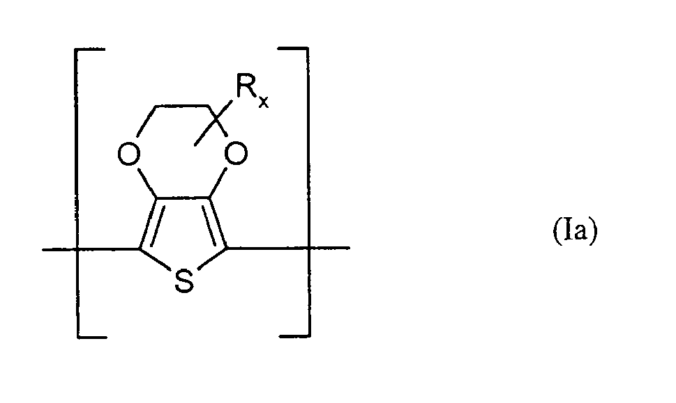
R und x die oben genannte Bedeutung haben.In preferred embodiments of the formulation according to the invention, at least one polythiophene containing repeating units of the general formula (I) is one containing repeating units of the general formula (Ia),
R and x have the abovementioned meaning.
In ganz besonders bevorzugten Formulierungen gemäß obiger Beschreibung steht x für 0 oder 1. Für den Fall, dass x gleich 1 ist, steht R besonders bevorzugt für Methyl oder Hydroxymethyl.In very particularly preferred formulations as described above, x is 0 or 1. In the event that x is 1, R is particularly preferably methyl or hydroxymethyl.
In weiteren bevorzugten Ausführungsformen der erfindungsgemäßen Formulierung ist wenigstens ein Polythiophen A) enthaltend wiederkehrende Einheiten der allgemeinen Formel (I) ein solches enthaltend wiederkehrende Einheiten der allgemeinen Formel (Iaa)

Unter dem Präfix Poly- ist im Rahmen der Erfindung zu verstehen, dass mehr als eine gleiche oder verschiedene wiederkehrende Einheit im Polymeren bzw. Polythiophen enthalten ist. Die Polythiophene enthalten insgesamt n wiederkehrende Einheiten der allgemeinen Formel (I), wobei n eine ganze Zahl von 2 bis 2000, bevorzugt 2 bis 100, sein kann. Die wiederkehrenden Einheiten der allgemeinen Formel (I) können innerhalb eines Polythiophens jeweils gleich oder verschieden sein. Bevorzugt sind Polythiophene enthaltend jeweils gleiche wiederkehrende Einheiten der allgemeinen Formel (I).In the context of the invention, the prefix poly- is understood to mean that more than one identical or different recurring unit is contained in the polymer or polythiophene. The polythiophenes contain a total of n repeating units of the general formula (I), where n can be an integer from 2 to 2000, preferably 2 to 100. The repeating units of general formula (I) may be the same or different within each polythiophene. Preference is given to polythiophenes containing in each case identical recurring units of the general formula (I).
Unter wiederkehrenden Einheiten sind im Rahmen der Erfindung Einheiten der allgemeinen Formeln (I), (Ia) oder (Iaa), im Folgenden als wiederkehrende Einheiten der allgemeinen Formel (I) zusammengefasst, zu verstehen, unabhängig davon, ob sie einmal oder mehrmals im Polythiophen enthalten sind. D.h. Einheiten der allgemeinen Formel (I) sind auch dann als wiederkehrende Einheiten zu verstehen, wenn sie nur einmal im Polythiophen enthalten sind.In the context of the invention, recurring units are to be understood as meaning units of the general formulas (I), (Ia) or (Iaa), hereinafter referred to as recurring units of the general formula (I), irrespective of whether they are present once or several times in the polythiophene are included. That Units of the general formula (I) are to be understood as repeating units even if they are contained only once in the polythiophene.
Erfindungsgemäße Formulierungen können auch solche sein, die neben wenigstens einem der vorangehend beschriebenen Polythiophene A) enthaltend wiederkehrende Einheiten der allgemeinen Formel (I) in der Mischung weitere leitfähige Polymere, wie Polyaniline oder Polypyrrole enthalten.Formulations according to the invention may also be those which, in addition to at least one of the above-described polythiophenes A) containing repeating units of the general formula (I) in the mixture, contain further conductive polymers, such as polyanilines or polypyrroles.
An den Endgruppen tragen die Polythiophene bevorzugt jeweils H.At the end groups, the polythiophenes preferably carry H.
Die Polythiophene A) enthalten insgesamt n wiederkehrende Einheiten der allgemeinen Formel (I), wobei n bevorzugt eine ganze Zahl von 2 bis 1000, bevorzugt 3 bis 100, besonders bevorzugt 4 bis 15 ist.The polythiophenes A) contain a total of n repeating units of the general formula (I), where n is preferably an integer from 2 to 1000, preferably 3 to 100, particularly preferably 4 to 15.
C1-C5-Alkylenreste A sind insbesondere Methylen, Ethylen, n-Propylen, n-Butylen oder n-Pentylen. C1-C18-Alkyl steht insbesondere für lineare oder verzweigte C1-C18-Alkylreste, beispielsweise Methyl, Ethyl, n- oder iso-Propyl, n-, iso-, sec- oder tert-Butyl, n-Pentyl, 1-Methylbutyl, 2-Methylbutyl, 3-Methylbutyl, 1-Ethylpropyl, 1,1-Dimethylpropyl, 1,2-Dimethylpropyl, 2,2-Dimethylpropyl, n-Hexyl, n-Heptyl, n-Octyl, 2-Ethylhexyl, n-Nonyl, n-Decyl, n-Undecyl, n-Dodecyl, n-Tridecyl, n-Tetradecyl, n-Hexadecyl oder n-Octadecyl, C5-C12-Cycloalkyl für C5-C12-Cycloalkylreste wie beispielsweise Cyclopentyl, Cyclohexyl, Cycloheptyl, Cyclooctyl, Cyclononyl oder Cyclodecyl, C5-C14-Aryl für C5-C14-Arylreste, beispielsweise Phenyl oder Naphthyl, und C7-C18-Aralkyl für C7-C18-Aralkylreste, beispielsweise Benzyl, o-, m-, p-Tolyl, 2,3-, 2,4-, 2,5-, 2,6-, 3,4-, 3,5-Xylyl oder Mesityl. Die vorangehende Aufzählung dient der beispielhaften Erläuterung der Erfindung und ist nicht als abschließend zu betrachten.C 1 -C 5 -alkylene radicals A are in particular methylene, ethylene, n-propylene, n-butylene or n-pentylene. C 1 -C 18 -alkyl is in particular linear or branched C 1 -C 18 -alkyl radicals, for example methyl, ethyl, n- or iso-propyl, n-, iso-, sec- or tert-butyl, n-pentyl, 1-methylbutyl, 2-methylbutyl, 3-methylbutyl, 1-ethylpropyl, 1,1-dimethylpropyl, 1,2-dimethylpropyl, 2,2-dimethylpropyl, n-hexyl, n-heptyl, n-octyl, 2-ethylhexyl, n-nonyl, n-decyl, n-undecyl, n-dodecyl, n-tridecyl, n-tetradecyl, n-hexadecyl or n-octadecyl, C 5 -C 12 cycloalkyl for C 5 -C 12 cycloalkyl radicals such as cyclopentyl, cyclohexyl, cycloheptyl, cyclooctyl, cyclononyl or cyclodecyl; C 5 -C 14 -aryl for C; 5 -C 14 -aryl radicals, for example phenyl or naphthyl, and C 7 -C 18 -aralkyl for C 7 -C 18 -aralkyl radicals, for example benzyl, o-, m-, p-tolyl, 2,3-, 2,4 -, 2,5-, 2,6-, 3,4-, 3,5-xylyl or mesityl. The preceding list serves to exemplify the invention and is not to be considered as exhaustive.
Die Herstellung der vorangehend beschriebenen Polythiophene A) enthaltend wiederkehrende Einheiten der allgemeinen Formel (I) ist prinzipiell in
Die Polymerisation der entsprechenden monomeren Ausgangsverbindungen wird mit geeigneten Oxidationsmitteln in geeigneten Lösungsmitteln durchgeführt. Beispiele für geeignete Oxidationsmittel sind Eisen(III)-salze, insbesondere FeCl3 und Eisen(III)-salze aromatischer und aliphatischer Sulfonsäuren, H2O2, K2Cr2O7, K2S2O8, Na2S2O8, KMnO4, Alkaliperborate und Alkali- oder Ammoniumpersulfate oder Mischungen dieser Oxidationsmittel. Weitere geeignete Oxidationsmittel sind beispielsweise in
Geeignete Lösungsmittel für die vorgenannte Reaktion sind z.B. polare Lösungsmittel, beispielsweise Wasser, Alkohole wie Methanol, Ethanol, 2-Propanol, n-Propanol, n-Butanol, Diacetonalkohol, Ethylenglykol, Glycerin oder Mischungen aus diesen. Ebenfalls geeignet sind aliphatische Ketone wie Aceton und Methylethylketon, aliphatische Nitrile wie Acetonitril, aliphatische und cyclische Amide wie N,N-Dimethylacetamid, N,N-Dimethylformamid (DMF) und 1-Methyl-2-pyrrolidon (NMP), Ether wie Tetrahydrofuran (THF) sowie Sulfoxide wie Dimethylsulfoxid (DMSO) oder Mischungen aus diesen untereinander oder mit den vorangehend aufgeführten Lösungsmitteln.Suitable solvents for the aforesaid reaction are e.g. polar solvents, for example water, alcohols such as methanol, ethanol, 2-propanol, n-propanol, n-butanol, diacetone alcohol, ethylene glycol, glycerol or mixtures thereof. Also suitable are aliphatic ketones such as acetone and methyl ethyl ketone, aliphatic nitriles such as acetonitrile, aliphatic and cyclic amides such as N, N-dimethylacetamide, N, N-dimethylformamide (DMF) and 1-methyl-2-pyrrolidone (NMP), ethers such as tetrahydrofuran ( THF) and sulfoxides such as dimethyl sulfoxide (DMSO) or mixtures of these with each other or with the solvents listed above.
Die entsprechenden monomeren Verbindungen zur Herstellung von Polythiophenen A) enthaltend wiederkehrende Einheiten der allgemeinen Formel (I) sind bekannt. Ihre Herstellung ist beispielsweise durch Umsetzung der Alkalisalze der 3,4-Dihydroxythiophen-2,5-dicarbonsäureester mit den entsprechenden Alkylen-dihalogeniden und nachfolgende Decarboxylierung der freien 3,4-(Alkylendioxy)thiophen-2,5-dicarbonsäuren möglich (siehe z. B.
Die resultierenden Polythiophene sind sehr gut in den polaren Lösungsmitteln oder Lösungsmittelgemischen löslich oder dispergierbar.The resulting polythiophenes are very soluble or dispersible in the polar solvents or solvent mixtures.
Die erfindungsgemäßen Formulierungen enthalten neben wenigstens einem teilfluorierten bzw. perfluorierten Polymer C) wenigstens ein weiteres SO3 -M+- oder COO-M+-Gruppen enthaltendes Polymer B). Geeignete SO3 -M+- oder COO-M+-Gruppen enthaltende Polymere B) sind bevorzugt solche, die keine vollständig konjugierte Hauptkette enthalten, im Folgenden auch kurz als nicht konjugiert bezeichnet. Beispielhaft für geeignete SO3 -M+- oder COO-M+-Gruppen enthaltende Polymere B) seien polymere Carbonsäuren, wie Polyacrylsäuren, Polymethacrylsäure oder Polymaleinsäuren, oder polymere Sulfonsäuren, wie Polystyrolsulfonsäuren und Polyvinylsulfonsäuren genannt. Weiterhin kommen auch Copolymere von Vinylcarbon- und Vinylsulfonsäuren mit anderen polymerisierbaren Monomeren, wie Acrylsäureestern und Styrol, in Frage. Besonders geeignet sind Polystyrolsulfonsäure, Poly-(styrolsulfonsäure-co-maleinsäure) oder Poly-(vinylsulfonsäure). Ganz besonders geeignete Formulierungen sind dadurch gekennzeichnet, dass sie als wenigstens ein SO3 -M+- oder COO-M+-Gruppen enthaltendes Polymer B) Polystyrolsulfonsäure (PSS) enthalten.The formulations according to the invention comprise, in addition to at least one partially fluorinated or perfluorinated polymer C), at least one further polymer B) containing SO 3 - M + or COO - M + groups. Suitable polymers B) containing SO 3 - M + or COO - M + groups are preferably those which do not contain a completely conjugated main chain, hereinafter also referred to as non-conjugated for short. Examples of suitable polymers containing SO 3 - M + or COO - M + groups are polymeric carboxylic acids, such as polyacrylic acids, polymethacrylic acid or polymaleic acids, or polymeric sulfonic acids, such as polystyrenesulfonic acids and polyvinylsulfonic acids. Also suitable are copolymers of vinylcarboxylic and vinylsulfonic acids with other polymerizable monomers, such as acrylic acid esters and styrene. Particularly suitable are polystyrenesulfonic acid, poly (styrenesulfonic acid-co-maleic acid) or poly (vinylsulfonic acid). Very particularly suitable formulations are characterized in that they contain polystyrene sulfonic acid (PSS) as polymer B) containing at least one SO 3 - M + or COO - M + group.
Bevorzugt sind diese Polymere B) in polaren Lösungsmitteln wie Wasser, Alkoholen wie Methanol, Ethanol, 2-Propanol, n-Propanol, n-Butanol, Diacetonalkohol, Ethylenglykol, Glycerin, aliphatischen Ketonen wie Aceton und Methylethylketon, aliphatischen Nitrilen wie Acetonitril, aliphatischen und cyclischen Amiden wie N,N-Dimethylacetamid, N,N-Dimethylformamid (DMF) und 1-Methyl-2-pyrrolidon (NMP), Ethern wie Tetrahydrofuran (THF) sowie Sulfoxiden wie Dimethylsulfoxid (DMSO) oder Mischungen enthaltend diese, bevorzugt in Wasser, Alkoholen wie Methanol, Ethanol, 2-Propanol, n-Propanol und n-Butanol oder Mischungen aus diesen löslich oder dispergierbar.These polymers are preferably B) in polar solvents such as water, alcohols such as methanol, ethanol, 2-propanol, n-propanol, n-butanol, diacetone alcohol, ethylene glycol, glycerol, aliphatic ketones such as acetone and methyl ethyl ketone, aliphatic nitriles such as acetonitrile, aliphatic and cyclic amides such as N, N-dimethylacetamide, N, N-dimethylformamide (DMF) and 1-methyl-2-pyrrolidone (NMP), ethers such as tetrahydrofuran (THF) and sulfoxides such as dimethyl sulfoxide (DMSO) or mixtures containing these, preferably in water , Alcohols such as methanol, ethanol, 2-propanol, n-propanol and n-butanol or mixtures of these soluble or dispersible.
Besonders geeignete Formulierungen gemäß obiger Beschreibung sind dadurch gekennzeichnet, dass sie als wenigstens ein SO3 -M+- oder COO-M+-Gruppen enthaltendes teilfluoriertes oder perfluoriertes Polymer C) beispielsweise solche enthaltend wiederkehrende Einheiten der Formeln (II-a) und (II-b),

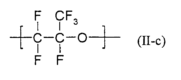
In besonders bevorzugten Ausführungsformen enthält die neue Formulierung als wenigstens ein SO3 -M+- oder COO-M+-Gruppen enthaltendes Polymer C) Nafion® (Copolymer aus Tetrafluorethylen und dem Trifluorvinylether des Poly(hexafluorpropylenoxid)mono(tetrafluorvinylsulfonsäure)-ethers).In particularly preferred embodiments, the novel formulation contains as at least one SO 3 - M + or COO - M + group-containing polymer C) Nafion® (copolymer of tetrafluoroethylene and the trifluorovinyl ether of poly (hexafluoropropylene oxide) mono (tetrafluorovinylsulfonic acid) ether).
Besonders bevorzugt werden Formulierungen, die als SO3 -M+- oder COO-M+-Gruppen enthaltendes Polymer B) Polystyrolsulfonsäure (PSS) und als SO3 -M+- oder COO-M+-Gruppen enthaltendes teilfluoriertes oder perfluoriertes Polymer C) Nafion® (Copolymer aus Tetrafluorethylen und dem Trifluorvinylether des Poly(hexafluorpropylenoxid)mono(tetrafluorvinylsulfonsäure)-ethers) enthalten.Particular preference is given to formulations containing the polymer containing SO 3 - M + or COO - M + groups B) polystyrenesulfonic acid (PSS) and partially fluorinated or perfluorinated polymer containing SO 3 - + or COO - M + groups C) Nafion® (copolymer of tetrafluoroethylene and the trifluorovinyl ether of poly (hexafluoropropylene oxide) mono (tetrafluorovinylsulfonic acid) ether).
Das Molekulargewicht der Polysäuren beträgt vorzugsweise 1 000 bis 2 000 000, besonders bevorzugt 2 000 bis 500 000. Die Polysäuren oder ihre Alkalisalze sind im Handel erhältlich, z.B. Polystyrolsulfonsäuren und Polyacrylsäuren, oder aber nach bekannten Verfahren herstellbar (siehe z.B. Houben Weyl, Methoden der organischen Chemie, Bd. E 20 Makromolekulare Stoffe, Teil 2, (1987), S. 1141 u.f).The molecular weight of the polyacids is preferably 1,000 to 2,000,000, more preferably 2,000 to 500,000. The polyacids or their alkali salts are commercially available, e.g. Polystyrenesulphonic acids and polyacrylic acids, or else can be prepared by known processes (see, for example, Houben Weyl, Methoden der organischen Chemie, Vol. E 20 Macromolecular Substances, Part 2, (1987), pp. 1141 et seq.).
Ganz besonders bevorzugt sind Formulierungen bei denen das Gewichtsverhältnis von Polythiophen(en) A) zu SO3 -M+- oder COO-M+-Gruppen enthaltendem(n) Polymer(en) B) von 1 zu 2 (1:2) bis 1 zu 25 (1:25), bevorzugt von 1 zu 2 (1:2) bis 1 zu 20 (1:20) beträgt.Very particular preference is given to formulations in which the weight ratio of polythiophene (s) A) to polymer (s) B) containing SO 3 - M + or COO - M + groups is from 1 to 2 (1: 2) to 1 to 25 (1:25), preferably from 1 to 2 (1: 2) to 1 to 20 (1:20).
Weiterhin ganz besonders bevorzugt sind Formulierungen bei denen das Gewichtsverhältnis von Polythiophen(en) A) zu SO3 -M+- oder COO-M+-Gruppen enthaltendem(n), teilfluoriertem(n) oder perfluoriertem(n) Polymer(en) C) von 1 zu 1 (1:1) bis 1 zu 50 (1:50), bevorzugt von 1 zu 2 (1:2) bis 1 zu 30 (1:30) beträgt.Very particular preference is furthermore given to formulations in which the weight ratio of polythiophene (s) A) to SO 3 - M + or COO - M + -group-containing, partially fluorinated or perfluorinated polymer (s) C ) from 1 to 1 (1: 1) to 1 to 50 (1:50), preferably from 1 to 2 (1: 2) to 1 to 30 (1:30).
Alle beliebigen Kombinationen der beiden vorangehend beschriebenen Gewichtsverhältnisse von Polythiophen(en) A) zu SO3 -M+- oder COO-M+-Gruppen enthaltendem(n) Polymer(en) B) und Polythiophen(en) A) zu SO3 -M+- oder COO-M+-Gruppen enthaltendem(n), teilfluoriertem(n) oder perfluoriertem(n) Polymer(en) C) können in den bevorzugten Formulierungen realisiert sein und gelten hiermit als offenbart.Any combination of the two weight ratios of polythiophene (s) A) to SO 3 - M + or COO - M + group - containing polymer (s) B) and Polythiophene (s) A) to SO 3 - M + or COO - M + -group-containing, partially fluorinated or perfluorinated polymer (s) C) may be realized in the preferred formulations and hereby apply as revealed.
Weiterhin können die neuen Formulierungen zusätzlich wenigstens ein polares Verdünnungsmittel D) (polares Lösungsmittel) enthalten. Unter polaren Verdünnungsmitteln D) (polaren Lösungsmitteln) sind im Rahmen der Erfindung Verdünnungsmittel mit einem Löslichkeitsparameter δ von 16 MPa1/2 und größer, bevorzugt 19 MPa1/2 und größer zu verstehen. Die Messung von Löslichkeitsparametern findet in der Regel bei Standardtemperatur (20°C) statt. Zur Messung und Berechnung von Löslichkeitsparametern siehe J. Brandrup et al., Polymer Handbook, 4th Ed., 1999, VII/675 - VII/688. Löslichkeitsparameter sind tabelliert, z.B. in J. Brandrup et al., Polymer Handbook, 4th Ed., 1999, VII/688 - VII/697. Bevorzugte polare Verdünnungsmittel D) sind Wasser, Alkohole wie Methanol, Ethanol, 2-Propanol, n-Propanol, n-Butanol, Diacetonalkohol, Ethylenglykol, Glycerin, aliphatische Ketone wie Aceton und Methylethylketon, aliphatische Nitrile wie Acetonitril, aliphatische und cyclische Amide wie N,N-Dimethylacetamid, N,N-Dimethylformamid (DMF) und 1-Methyl-2-pyrrolidon (NMP), Ether wie Tetrahydrofuran (THF) sowie Sulfoxide wie Dimethylsulfoxid (DMSO) oder Mischungen enthaltend diese. Besonders bevorzugte polare Verdünnungsmittel D) sind Wasser, Alkohole oder Mischungen enthaltend diese, ganz besonders bevorzugt sind Wasser, Methanol, Ethanol, n-Propanol, 2-Propanol oder n-Butanol oder Mischungen enthaltend diese. In bevorzugten Ausführungsformen enthalten die neuen Formulierungen als polares Verdünnungsmittel D) Mischungen aus Wasser und wenigstens einem Alkohol.Furthermore, the new formulations may additionally contain at least one polar diluent D) (polar solvent). In the context of the invention, polar diluents D) (polar solvents) are to be understood as meaning diluents having a solubility parameter δ of 16 MPa 1/2 and greater, preferably 19 MPa 1/2 and greater. The measurement of solubility parameters usually takes place at standard temperature (20 ° C). For measurement and calculation of solubility parameters, see J. Brandrup et al., Polymer Handbook, 4 th Ed., 1999, VII / 675 - VII / 688. Solubility parameters are tabulated, eg in J. Brandrup et al., Polymer Handbook, 4 th Ed., 1999, VII / 688 - VII / 697. Preferred polar diluents D) are water, alcohols such as methanol, ethanol, 2-propanol, n-propanol, n-butanol, diacetone alcohol, ethylene glycol, glycerol, aliphatic ketones such as acetone and methyl ethyl ketone, aliphatic nitriles such as acetonitrile, aliphatic and cyclic amides such as N , N-dimethylacetamide, N, N-dimethylformamide (DMF) and 1-methyl-2-pyrrolidone (NMP), ethers such as tetrahydrofuran (THF) and sulfoxides such as dimethyl sulfoxide (DMSO) or mixtures containing them. Particularly preferred polar diluents D) are water, alcohols or mixtures containing them, very particular preference is given to water, methanol, ethanol, n-propanol, 2-propanol or n-butanol or mixtures thereof. In preferred embodiments, the novel formulations contain as polar diluent D) mixtures of water and at least one alcohol.
Solche neuen bevorzugten Formulierungen enthaltend wenigstens ein polares Verdünnungsmittel D) enthalten bevorzugt 99.99 bis 80 Gew.-%, besonders bevorzugt 99,8 bis 95 Gew.-% polare(s) Verdünnungsmittel und weisen einen Feststoffgehalt von 0,01 bis 20 Gew.-%, besonders bevorzugt 0,2 bis 5 Gew.-% auf, d.h. enthalten insgesamt 0,01 bis 20 Gew.-%, besonders bevorzugt 0,2 bis 5 Gew.-% Polythiophen(e) A), SO3 -M+- oder COO-M+-Gruppen enthaltende(s) Polymer(e) B) und C) und gegebenenfalls weitere enthaltene Komponenten, wie z.B. Bindemittel, Vernetzungsmittel und/oder Tenside, in gelöster und/oder dispergierter Form.Such novel preferred formulations containing at least one polar diluent D) preferably contain 99.99 to 80% by weight, particularly preferably 99.8 to 95% by weight, of polar diluents and have a solids content of 0.01 to 20% by weight. %, more preferably 0.2 to 5 wt .-%, ie contain a total of 0.01 to 20 wt .-%, particularly preferably 0.2 to 5 wt .-% polythiophene (s) A), SO 3 - M + - or COO - M + groups-containing (s) polymer (s) B) and C) and optionally further components included, such as binders, crosslinking agents and / or surfactants, in dissolved and / or dispersed form.
Die Viskosität bei 20°C von neuen bevorzugten Formulierungen enthaltend wenigstens ein polares Verdünnungsmittel liegt zwischen der Viskosität des Verdünnungsmittels und 200 mPas, bevorzugt < 100 mPas.The viscosity at 20 ° C of new preferred formulations containing at least one polar diluent is between the viscosity of the diluent and 200 mPas, preferably <100 mPas.
Zur Einstellung des gewünschten Feststoffgehaltes und der erforderlichen Viskosität kann aus den Formulierungen die gewünschte Menge Verdünnungsmittel durch Destillation, bevorzugt im Vakuum, oder durch andere Verfahren, z.B. Ultrafiltration, entfernt werden.To set the desired solids content and the required viscosity can be removed from the formulations, the desired amount of diluent by distillation, preferably in vacuo, or by other methods, such as ultrafiltration.
Den erfindungsgemäßen Formulierungen können außerdem organische, polymere Bindemittel und/oder organische, niedermolekulare Vernetzungsmittel oder Tenside zugesetzt werden. Entsprechende Bindemittel sind z.B. in
Die Formulierungen können bevorzugt geringe Mengen ionischer Verunreinigungen in den Grenzen wie sie in
Die erfindungsgemäßen Formulierungen können auf einfache Weise hergestellt werden. Beispielsweise ist es möglich, eine bereits fertige Mischung enthaltend wenigstens ein SO3 -M+- oder COO-M+-Gruppen enthaltendes Polymer B) und wenigstens ein Polythiophen A) mit wenigstens einem teilfluorierten oder perfluorierten, SO3 -M+- oder COO-M+-Gruppen enthaltenden Polymer C) zu mischen und dieses Gemisch gegebenenfalls mit wenigstens einem Verdünnungsmittel zu versetzen, bevorzugt in wenigstens einem Verdünnungsmittel ganz oder teilweise zu lösen oder zu dispergieren. Es ist auch möglich, wenigstens eine bereits fertige Mischung enthaltend ein SO3 -M+- oder COO-M+-Gruppen enthaltendes Polymer B) und wenigstens ein Polythiophen A) vorab mit wenigstens einem Verdünnungsmittel D) zu versetzen, bevorzugt in wenigstens einem Verdünnungsmittel D) ganz oder teilweise zu lösen oder zu dispergieren, wenigstens ein SO3 -M+- oder COO-M+-Gruppen enthaltendes teilfluoriertes oder perfluoriertes Polymer C) in einem Verdünnungsmittel zu lösen oder zu dispergieren und die Lösung(en) und/oder Dispersion(en) anschließend zu mischen. Gegebenenfalls kann aus dieser Mischung anschließend das Verdünnungsmittel D) oder Verdünnungsmittelgemisch ganz oder teilweise wieder entfernt werden, z.B. durch Destillation oder andere Verfahren.The formulations according to the invention can be prepared in a simple manner. For example, it is possible to use an already finished mixture comprising at least one polymer B) containing SO 3 - M + or COO - M + groups and at least one polythiophene A) having at least one partially fluorinated or perfluorinated, SO 3 - M + or COO - M + groups containing polymer C) and to admix this mixture optionally with at least one diluent, preferably in at least one diluent to dissolve or disperse in whole or in part. It is also possible to add at least one previously prepared mixture containing a polymer B) containing SO 3 - M + or COO - M + groups and at least one polythiophene A) in advance with at least one diluent D), preferably in at least one diluent (D) dissolve or disperse in whole or in part, dissolve or disperse at least one partially fluorinated or perfluorinated polymer C) containing SO 3 - M + or COO - M + groups in a diluent and dissolve the solution (s) and / or Then mix the dispersion (s). Optionally, the diluent D) or diluent mixture can be completely or partially removed from this mixture, for example by distillation or other methods.
Überraschend eignen sich die erfindungsgemäßen Formulierungen hervorragend für die Herstellung lochinjizierender oder lochtransportierender Schichten in EL-Anordnungen, organischen Solarzellen, organischen Laserdioden, organischen Dünnfilmtransistoren oder organischen Feldeffekttransistoren, zur Herstellung von Elektroden oder elektrisch leitfähiger Beschichtungen.Surprisingly, the formulations according to the invention are outstandingly suitable for the production of hole-injecting or hole-transporting layers in EL devices, organic solar cells, organic laser diodes, organic thin-film transistors or organic field-effect transistors, for the production of electrodes or electrically conductive coatings.
Daher ist ebenfalls Gegenstand der vorliegenden Erfindung die Verwendung der erfindungsgemäßen Formulierungen zur Herstellung lochinjizierender Schichten in EL-Anordnungen, zur Herstellung von Elektroden oder elektrisch leitfähiger Beschichtungen.The present invention accordingly also provides the use of the formulations according to the invention for producing hole-injecting layers in EL arrangements, for producing electrodes or electrically conductive coatings.
Diese EL-Anordnungen findet Verwendung als Anzeigeelemente ("Displays"), z. B. in Flach-Bildschirmen wie Laptop, Pager, Mobiltelefon, Navigationsgeräte, Auto-Radios, Kfz-Instrumententafeln, oder als Flächenstrahler, z.B. Lampen, Leuchtflächen, Hintergrundbeleuchtung für LCD-Displays, Schilder.These EL devices are used as display elements ("displays"), e.g. In flat screens such as laptops, pagers, cell phones, sat navs, car radios, automotive instrument panels, or as panel radiators, eg lamps, illuminated areas, backlighting for LCD displays, signs.
Insbesondere EL-Anordnungen mit einer lochinjizierenden Schicht enthaltend eine erfindungsgemäße Formulierung zeichnen sich durch eine hohe Leuchtstärke (Leuchtintensität) und eine deutlich höhere Lebensdauer aus als bekannte EL-Anordnungen.In particular, EL arrangements with a hole-injecting layer containing a formulation according to the invention are distinguished by a high luminous intensity (luminous intensity) and a significantly longer service life than known EL arrangements.
Ebenfalls Gegenstand der vorliegenden Erfindung sind daher EL-Anordnungen insbesondere Leuchtdioden enthaltend eine lochinjizierende Schicht enthaltend eine erfindungsgemäße Formulierung. Bevorzugt sind dies solche EL-Anordnungen enthaltend wenigstens zwei Elektroden, wovon gegebenenfalls wenigstens eine auf ein gegebenenfalls transparentes Substrat aufgebracht ist, wenigstens eine Emitter-Schicht zwischen den beiden Elektroden und wenigstens eine lochinjizierenden Schicht zwischen einer der beiden Elektroden und der Emitter-Schicht, dadurch gekennzeichnet, dass die lochinjizierende Schicht eine erfindungsgemäße Formulierung enthält.Likewise provided by the present invention are therefore EL arrangements, in particular light-emitting diodes comprising a hole-injecting layer containing a formulation according to the invention. These are preferably those EL arrangements comprising at least two electrodes, of which optionally at least one is applied to an optionally transparent substrate, at least one emitter layer between the two electrodes and at least one hole-injecting layer between one of the two electrodes and the emitter layer in that the hole-injecting layer contains a formulation according to the invention.
Bei der Herstellung von vielen großflächigen EL-Anordnungen, z.B. großflächigen elektrolumineszierenden Anzeigeelementen, ist es vorteilhaft, wenn mindestens eine der stromzuführenden Elektroden aus einem transparenten und leitfähigem Material besteht. Als solche transparenten und leitfähigen Elektroden-Materialien sind beispielsweise
- a) Metalloxide, z.B. Indium-Zinn-Oxid (ITO), Zinnoxid (NESA), dotiertes Zinnoxid, dotiertes Zinkoxid etc.,
- b) semi-transparente Metallfilme, z.B. Au, Pt, Ag, Cu etc.,
- c) semi-transparente, leitfähige Polymere, z.B. Polythiophene, Polyaniline, Polypyrrole etc.
- a) metal oxides, eg indium tin oxide (ITO), tin oxide (NESA), doped tin oxide, doped zinc oxide etc.,
- b) semi-transparent metal films, eg Au, Pt, Ag, Cu etc.
- c) semi-transparent, conductive polymers, eg polythiophenes, polyanilines, polypyrroles etc.
Bei einer Elektrode, die nicht aus einem der vorangehend aufgeführten transparenten und leitfähigen Materialien besteht, handelt es sich vorzugsweise um eine Metallelektrode, insbesondere um eine Metallkathode.An electrode which does not consist of one of the above listed transparent and conductive materials is preferably a metal electrode, in particular a metal cathode.
Geeignete Materialien für Metallkathoden sind die für elektrooptische Aufbauten gängigen Materialien und dem Fachmann bekannt. Als Metallkathode kommen bevorzugt solche aus Metallen mit geringer Austrittsarbeit wie Mg, Ca, Ba oder Metallsalzen wie LiF in Betracht.Suitable materials for metal cathodes are the commonly used for electro-optical structures materials and known in the art. As the metal cathode are preferably those of low work function metals such as Mg, Ca, Ba or metal salts such as LiF into consideration.
Als gegebenenfalls transparentes Substrat eignet sich beispielsweise Glas, Dünnstglas (flexibles Glas) oder Kunststoffe, bevorzugt Kunststofffolien.As an optionally transparent substrate is, for example, glass, thin glass (flexible glass) or plastics, preferably plastic films.
Besonders geeignete Kunststoffe für das Substrat sind: Polycarbonate, Polyester wie z.B. PET und PEN (Polyethylenterephthalat bzw. Polyethylennaphthalindicarboxylat), Copolycarbonate, Polyacrylat, Polysulfon, Polyethersulfon (PES), Polyimid, Polyethylen, Polypropylen oder cyclische Polyolefine bzw. cyclische Olefincopolymere (COC), hydrierte Styrolpolymere oder hydrierte Styrolcopolymere.Particularly suitable plastics for the substrate are: polycarbonates, polyesters, e.g. PET and PEN (polyethylene terephthalate or polyethylene naphthalene dicarboxylate), copolycarbonates, polyacrylate, polysulfone, polyethersulfone (PES), polyimide, polyethylene, polypropylene or cyclic polyolefins or cyclic olefin copolymers (COC), hydrogenated styrene polymers or hydrogenated styrene copolymers.
Geeignete Polymerunterlagen können beispielsweise Folien wie Polyesterfolien, PES-Folien der Firma Sumitomo oder Polycarbonatfolien der Firma Bayer AG (Makrofol®) sein.Suitable polymer substrates may be, for example, films such as polyester films, PES films from Sumitomo or polycarbonate films from Bayer AG (Makrofol®).
Zwischen dem Substrat und der Elektrode kann sich eine Haftvermittlerschicht befinden. Geeignete Haftvermittler sind beispielsweise Silane. Bevorzugt sind Epoxysilane, wie beispielsweise 3-Glycidoxypropyltrimethoxysilan (Silquest® A187, Fa. OSi specialities). Es können auch andere Haftvermittler mit hydrophilen Oberflächeneigenschaften verwendet werden. So wird z.B. eine dünne Schicht aus PEDT:PSS als geeigneter Haftvermittler für PEDT beschrieben (
In der Emitter-Schicht der erfindungsgemäßen EL-Anordnung ist wenigstens ein Emittermaterial enthalten. Geeignete Emittermaterialien sind die für elektrooptische Aufbauten gängigen und dem Fachmann bekannt. Als Emittermaterialien kommen bevorzugt konjugierte Polymere wie Polyphenylenvinylene und/oder Polyfluorene, wie die beispielsweise in
Zusätzlich zu den vorangehend aufgeführten Schichten können weitere funktionelle Schichten in einem solchen elektrolumineszierenden Schichtaufbau (EL-Anordnung) enthalten sein, wie z.B. weitere ladungsinjizierende, z.B. elektroneninjizierende, ladungstransportierende oder ladungsblockierende Zwischenschichten. Solche Schichtaufbauten sind dem Fachmann bekannt und beispielsweise in
Die prinzipielle Herstellung solcher EL-Anordnungen ist dem Fachmann bekannt. Sie können beispielsweise so hergestellt werden, dass eine Elektrode aus Lösung oder Dispersion oder durch Aufdampfen auf ein Substrat aufgebracht wird. Z.B. werden Metalloxid- oder semi-transparente Metallfilmelektroden bevorzugt durch Aufdampfen, semi-transparente, leitfähige Polymerelektroden hingegen bevorzugt aus Lösung oder Dispersion auf das Substrat aufgebracht. Gegebenenfalls kann vor Aufbringen des Elektrodenmaterials auf das Substrat ein Haftvermittler - durch Aufdampfen oder aus Lösung oder Dispersion - aufgebracht werden. Einige solcher mit Elektrodenmaterial beschichteten Substrate sind auch bereits kommerziell erhältlich (z.B. K-Glas, ITO beschichtete Glassubstrate). Auf die Elektrode kann anschließend die lochinjizierende Schicht aufgebracht werden, was bei den erfindungsgemäßen EL-Anordnungen mit lochinjizierender Schicht enthaltend eine erfindungsgemäße Formulierung vorteilhafterweise aus Lösung oder Dispersion erfolgt. Auf die lochinjizierende Schicht werden anschließend die weiteren Schichten in der einleitend aufgeführten Reihenfolge - unter Berücksichtigung, dass einzelne Schichten weggelassen werden können - je nach eingesetztem Material aus Lösung oder Dispersion oder durch Aufdampfen aufgebracht. Anschließend wird die Schichtanordnung kontaktiert und gekapselt.The basic production of such EL arrangements is known to the person skilled in the art. For example, they can be made by applying an electrode from solution or dispersion or by vapor deposition onto a substrate. For example, metal oxide or semi-transparent Metal film electrodes preferably by vapor deposition, semi-transparent, conductive polymer electrodes, however, preferably applied from solution or dispersion to the substrate. If appropriate, an adhesion promoter can be applied to the substrate before application of the electrode material - by vapor deposition or from solution or dispersion. Some such electrode material-coated substrates are already commercially available (eg K-glass, ITO coated glass substrates). The hole-injecting layer can then be applied to the electrode, which is advantageously carried out from solution or dispersion in the case of the EL arrangements with hole-injecting layer containing a formulation according to the invention. The further layers are then applied to the hole-injecting layer in the order listed below, taking into account that individual layers can be omitted, depending on the material used, from solution or dispersion or by vapor deposition. Subsequently, the layer arrangement is contacted and encapsulated.
Die Herstellung der lochinjizierenden Schicht enthaltend eine erfindungsgemäße Formulierung erfolgt nach bekannten Technologien. Dazu wird eine erfindungsgemäße Formulierung - gegebenenfalls in einem Lösungsmittel - auf einer Elektrode, bevorzugt der Basiselektrode, als Film aufgetragen. Als Lösungsmittel eignen sich die oben aufgeführten polaren Verdünnungsmittel, bevorzugt Wasser, Alkohole oder Mischungen aus diesen. Geeignete Alkohole sind z.B. Methanol, Ethanol, n-Propanol, 2-Propanol und n-Butanol.The production of the hole-injecting layer containing a formulation according to the invention is carried out according to known technologies. For this purpose, a formulation of the invention - optionally in a solvent - on an electrode, preferably the base electrode, applied as a film. Suitable solvents are the above-mentioned polar diluents, preferably water, alcohols or mixtures of these. Suitable alcohols are e.g. Methanol, ethanol, n-propanol, 2-propanol and n-butanol.
Die Verwendung dieser Lösungsmittel hat den Vorteil, dass weitere Schichten aus organischen Lösungsmitteln, wie aromatischen oder aliphatischen Kohlenwasserstoffgemischen aufgebracht werden können, ohne dass die lochinjizierende Schicht angegriffen wird.The use of these solvents has the advantage that further layers of organic solvents, such as aromatic or aliphatic hydrocarbon mixtures can be applied without the hole-injecting layer is attacked.
Die erfindungsgemäße Formulierung - gegebenenfalls in einem Lösungsmittel - kann beispielsweise durch Drucktechniken wie Spincoaten, Casting, Rakeln, Drucken, Vorhanggießen etc. auf der Elektrode gleichmäßig verteilt werden. Anschließend können die Schichten bei Raumtemperatur oder Temperaturen bis 300°C, bevorzugt 100 bis 200°C getrocknet werden.The formulation of the invention - optionally in a solvent - can be evenly distributed on the electrode, for example, by printing techniques such as spin coating, casting, knife coating, printing, curtain coating, etc. Subsequently, the layers can be dried at room temperature or temperatures up to 300 ° C., preferably 100 to 200 ° C.
Die erfindungsgemäße Formulierung - gegebenenfalls in einem Lösungsmittel - kann außerdem bevorzugt durch Techniken wie Ink-Jet strukturiert aufgebracht werden. Diese Technik ist dem Fachmann bekannt und unter Einsatz wasserlöslicher und dispergierter Polythiophene wie 3,4-Polyethylendioxythiophen:Polystyrolsulfonsäure (PEDT:PSS) z.B. in
Vorzugsweise werden die erfindungsgemäßen Formulierungen - gegebenenfalls in einem Lösungsmittel - vor der Applizierung durch ein Filter filtriert.Preferably, the formulations according to the invention - optionally in a solvent - are filtered through a filter prior to application.
Besonders gut zum Reinigen filtrierbare Formulierungen werden beispielsweise erhalten, wenn in Lösungsmittel D) bezogen auf ein Gewichtsteil Polythiophen(e) enthaltend wiederkehrende Einheiten der allgemeinen Formel (I) bevorzugt 1 bis 30 Gewichtsteile, besonders bevorzugt 2 bis 25 Gewichtsteile des oder der SO3 -M+- oder COO-M+-Gruppen enthaltende(n) Polymer(e) B) verwendet werden.Particularly well for cleaning filterable formulations are obtained, for example, if in solvent D) based on one part by weight of polythiophene (s) containing repeating units of the general formula (I) preferably 1 to 30 parts by weight, particularly preferably 2 to 25 parts by weight of the SO or SO 3 - M + or COO - M + groups containing polymer (s) B) can be used.
Die Dicke der lochinjizierenden Schicht beträgt beispielsweise 3 bis 500 nm, bevorzugt 10 bis 200 nm.The thickness of the hole-injecting layer is, for example, 3 to 500 nm, preferably 10 to 200 nm.
Der Einfluss einer lochinjizierenden Schicht enthaltend eine erfindungsgemäße Formulierung auf die Eigenschaften der EL-Anordnung kann in einem speziellen Aufbau einer solchen erfindungsgemäßen EL-Anordnung getestet werden. Dazu wird die lochinjizierende Schicht auf nasschemisch gereinigtes ITO-Substrat mittels Spin-Coater aufgebracht. Anschließend wird die Schicht bei 100-200°C für 5 min getrocknet. Die Schichtdicke beträgt je nach Spingeschwindigkeit 20-300 nm. Als Emitter-Schicht wird eine 1 gew.-%ige Lösung eines polyfluorenbasierten Emittermaterials (Green 1300 LUMATION™ der Fa. Dow Chemical Company) in Xylol aufgeschleudert. Die Dicke der Emitterschicht beträgt typischerweise 60-120 nm. Als Kathode wird abschließend eine 5 nm dicke Ba-Schicht und darauf eine 200 nm dicke Ag-Schicht aufgedampft. Durch Kontaktierung der Indiumzinnoxid(ITO)-Anode und der Metall-Kathode werden mittels eines Kennlinienschreibers und einer kalibrierten Photodiode Strom-Spannungs-Leuchtdichte-Kennlinien aufgenommen und Lebensdauern gemessen. Dazu wird durch die Anordnung ein konstanter elektrischer Strom oder ein Wechselstrom geschickt, und die Spannung und die Leuchtdichte werden zeitabhängig verfolgt.The influence of a hole-injecting layer containing a formulation according to the invention on the properties of the EL device can be tested in a specific structure of such an EL device according to the invention. For this purpose, the hole-injecting layer is applied to wet-chemically cleaned ITO substrate by means of spin coaters. Subsequently, the layer is dried at 100-200 ° C for 5 min. Depending on the spinning speed, the layer thickness is 20-300 nm. As the emitter layer, a 1% strength by weight solution of a polyfluorene-based emitter material (Green 1300 LUMATION ™ from Dow Chemical Company) is spin-coated in xylene. The thickness of the emitter layer is typically 60-120 nm. Finally, a 5 nm thick Ba layer and then a 200 nm thick Ag layer are evaporated on as the cathode. By contacting the indium tin oxide (ITO) anode and the metal cathode, current-voltage-luminance characteristics are recorded and lifetimes measured by means of a characteristic plotter and a calibrated photodiode. For this purpose, a constant electric current or an alternating current is sent through the arrangement, and the voltage and the luminance are tracked time-dependent.
Die erfindungsgemäßen organischen Leuchtdioden zeichnen sich durch hohe Lebensdauer, hohe Leuchtstärke, niedrige Einsatzspannungen und ein hohes Gleichrichtungsverhältnis aus. Im Vergleich zu bekannten Leuchtdioden mit lochinjizierenden Schichten hergestellt aus einer Poly(3,4-ethylendioxythiophen):Polystyrolsulfonsäure(PEDT:PSS)-Dispersion (Baytron® P, H.C. Starck GmbH) wurde überraschend gefunden, dass die Lebensdauern erfindungsgemäßer organischer Leuchtdioden mit lochinjizierender Schicht enthaltend eine erfindungsgemäße Formulierung signifikant höher sind.The organic light emitting diodes according to the invention are characterized by a long service life, high luminous intensity, low threshold voltages and a high ratio of rectification. In comparison with known light-emitting diodes with hole-injecting layers produced from a poly (3,4-ethylenedioxythiophene): polystyrenesulfonic acid (PEDT: PSS) dispersion (Baytron® P, HC Starck GmbH), it has surprisingly been found that the lifetimes of organic light-emitting diodes with a hole-injecting layer according to the invention containing a formulation according to the invention are significantly higher.
40g einer 1,32 %igen Poly(3,4-ethylendioxythiophen)/Polystyrolsulfonsäure-Lösung (H.C. Starck GmbH, Baytron® P Versuchsprodukt, TP AI 4083, Gew.-Verhältnis PEDT/PSS 1:6) werden mit 9,96 g einer 5,30 Gew.-% Lösung aus Nafion® in einem Gemisch aus niederaliphatischen Alkoholen und Wasser (Nafion® perfluorinated ion-exchange resin, 5 wt % solution in lower aliphatic alcohols/H2O, CAS-Nr. 66796-30-3, Aldrich-Best.-Nr. 27,470-4, nachgemessener Feststoffgehalt 5,30 Gew.-%) gemischt. Das Gewichts-Verhältnis von PEDT/PSS/Nafion® beträgt 1:6:7 .40 g of a 1.32% poly (3,4-ethylenedioxythiophene) / polystyrenesulfonic acid solution (HC Starck GmbH, Baytron® P experimental product, TP AI 4083, weight ratio PEDT / PSS 1: 6) are mixed with 9.96 g A 5.30% by weight solution of Nafion® in a mixture of lower aliphatic alcohols and water (Nafion® perfluorinated ion-exchange resin, 5% by weight solution in lower aliphatic alcohols / H 2 O, CAS No. 66796-30- 3, Aldrich No. 27,470-4, measured solids content 5.30% by weight). The weight ratio of PEDT / PSS / Nafion® is 1: 6: 7.
Die erfindungsgemäße Formulierung aus Beispiel 1 wird zum Aufbau einer organischen Leuchtdiode (OLED) genutzt. Bei der Herstellung der OLED wird folgendermaßen vorgegangen:The formulation of Example 1 according to the invention is used to construct an organic light-emitting diode (OLED). The OLED is manufactured as follows:
ITO-beschichtetes Glas (Merck Balzers AG, FL, Part. No. 253 674 XO) wird in 50 mm x 50 mmgroße Stücke (Substrate) geschnitten. Die ITO-Schicht wird mit üblicher Photoresisttechnik und anschließendem Abätzen in FeCl3-Lösung strukturiert. Die isolierten ITO-Streifen haben eine Breite von 2,0 mm. Die Substrate werden anschließend in 3 %iger wässriger Mukasollösung im Ultraschallbad 15 min lang gereinigt. Danach werden die Substrate mit destilliertem Wasser gespült und in einer Zentrifuge trocken geschleudert. Dieser Spül- und Trockenvorgang wird 10 mal wiederholt. Unmittelbar vor der Beschichtung werden die ITO-beschichteten Seiten in einem UV/Ozon-Reaktor (PR-100, UVP Inc., Cambridge, GB) für 10 min gereinigt.ITO-coated glass (Merck Balzers AG, FL, Part No. 253 674 XO) is cut into 50 mm x 50 mm pieces (substrates). The ITO layer is patterned by conventional photoresist technique and then etched in FeCl 3 solution. The insulated ITO strips have a width of 2.0 mm. The substrates are then cleaned in 3% aqueous Mukasollösung in an ultrasonic bath for 15 min. Thereafter, the substrates are rinsed with distilled water and spun dry in a centrifuge. This rinsing and drying process is repeated 10 times. Immediately prior to coating, the ITO coated sides are cleaned in a UV / ozone reactor (PR-100, UVP Inc., Cambridge, UK) for 10 minutes.
Etwa 10 ml der erfindungsgemäßen Formulierung aus Beispiel 1 werden filtriert (Millipore HV, 0,45 µm). Das gereinigte ITO-beschichtete Substrat wird auf eine Lackschleuder gelegt und die filtrierte Lösung wird auf der ITO-beschichteten Seite des Substrats verteilt. Anschließend wird die überstehende Lösung durch Rotation des Tellers bei 800 U/min mit geschlossenem Deckel über den Zeitraum von 30 s abgeschleudert. Danach wird das so beschichtete Substrat 5 min lang bei 200 °C auf einer Heizplatte getrocknet. Die Schichtdicke beträgt 85 nm (Tencor, Alphastep 500).About 10 ml of the formulation according to the invention from example 1 are filtered (Millipore HV, 0.45 μm). The cleaned ITO-coated substrate is placed on a spin coater and the filtered solution is spread on the ITO-coated side of the substrate. Subsequently, the supernatant solution is spun off by rotation of the plate at 800 rpm with the lid closed over the period of 30 s. Thereafter, the thus coated substrate is dried for 5 minutes at 200 ° C on a hot plate. The layer thickness is 85 nm (Tencor, Alphastep 500).
5 ml einer 1 Gew.-% Xylol-Lösung des Emitters Green 1300 LUMATION™ (Dow Chemical Company) werden filtriert (Millipore HV, 0,45 µm) und auf der getrockneten lochinjizierenden Schicht verteilt. Dieser und alle weiteren Prozessschritte werden in reiner N2-Atmosphäre durchgeführt (Inertgas-Gloveboxsystem, M.Braun, Garching). Die Lochinjektionsschicht wird zuvor in der Glovebox nochmals für 5 min bei 200 °C nachgetrocknet. Anschließend wird die überstehende Lösung des Emitters durch Rotation des Tellers bei 400 U/min mit geschlossenem Deckel 30 s lang abgeschleudert. Danach wird das so beschichtete Substrat 15 min lang bei 130 °C auf einer Heizplatte getrocknet. Die Gesamtschichtdicke beträgt 185 nm.5 ml of a 1% by weight xylene solution of the Green 1300 LUMATION ™ emitter (Dow Chemical Company) are filtered (Millipore HV, 0.45 μm) and spread on the dried hole-injecting layer. This and all other process steps are carried out in pure N 2 atmosphere (inert gas glove box system, M.Braun, Garching). The hole injection layer is previously further dried in the glove box for 5 min at 200 ° C. Subsequently, the supernatant solution of the emitter is spun off for 30 s by rotating the plate at 400 rpm with the lid closed. Thereafter, the thus coated substrate is dried for 15 minutes at 130 ° C on a hot plate. The total layer thickness is 185 nm.
Auf die Emitterschicht wird eine Metallelektrode gedampft. Das Substrat wird mit der Emitterschicht nach unten auf eine Streifenmaske mit 2,0 mm breiten Streifen gelegt, die senkrecht zu den ITO-Streifen orientiert ist. Aus zwei Aufdampfschiffchen werden bei einem Druck von p = 10-3 Pa nacheinander eine 5 nm dicke Ba-Schicht und anschließend eine 200 nm dicke Ag-Schicht aufgedampft. Die Aufdampfraten betragen 10 Å/s für Ba und 20 Å/s für Ag. Die aktive Leuchtfläche am Kreuzungspunkt der beiden Elektroden beträgt 4 mm2.On the emitter layer, a metal electrode is evaporated. The substrate is placed with the emitter layer facing down on a stripe mask with 2.0 mm wide strips oriented perpendicular to the ITO strips. From two Aufdampfschiffchen a 5 nm thick Ba layer and then a 200 nm thick Ag layer are vapor-deposited successively at a pressure of p = 10 -3 Pa. The vapor deposition rates are 10 Å / s for Ba and 20 Å / s for Ag. The active luminous area at the intersection of the two electrodes is 4 mm 2 .
Die leicht oxidierbaren Kathoden werden durch Verkapselung vor Korrosion geschützt. Dazu wird die polymeren Schichten manuell am Rand des Substrats mit einem Skalpell entfernt und es wird eine Metallkappe (35mm x 35mm x2mm) als Schutz mit einem Epoxydkleber (UHU Plus, UHU, D) aufgeklebt. In der Metallkappe wird zusätzlich Feuchtigkeitsabsorber (GDO/CA/18x10x0.4, SAES Getters S.p.A., Italien) gesetzt.The easily oxidizable cathodes are protected from corrosion by encapsulation. For this purpose, the polymer layers are manually removed at the edge of the substrate with a scalpel and it is a metal cap (35mm x 35mm x2mm) as protection with an epoxy adhesive (UHU Plus, UHU, D) glued. Moisture absorber (GDO / CA / 18x10x0.4, SAES Getters S.p.A., Italy) is additionally set in the metal cap.
Die beiden Elektroden der organischen LED werden über elektrische Zuführungen mit einer Spannungsquelle verbunden (kontaktiert). Der positive Pol ist mit der ITO-Elektrode, der negative Pol ist mit der Metall-Elektrode verbunden. Die Abhängigkeit des OLED-Stroms und der Elektrolumineszenzintensität (der Nachweis erfolgt mit einer Photodiode (EG&G C30809E)) von der Spannung werden aufgezeichnet. Anschließend wird die Lebensdauer bestimmt, indem ein konstanter Strom von I = 0.32 mA (8 mA/cm2) durch die Anordnung fließt, und die Spannung und Lichtintensität zeitabhängig verfolgt.The two electrodes of the organic LED are connected (contacted) via electrical leads to a voltage source. The positive pole is connected to the ITO electrode, the negative pole is connected to the metal electrode. The dependence of the OLED current and the electroluminescence intensity (the detection is carried out with a photodiode (EG & G C30809E)) of the voltage are recorded. Subsequently, the lifetime is determined by flowing a constant current of I = 0.32 mA (8 mA / cm 2 ) through the array, and tracking the voltage and light intensity over time.
Herstellung einer OLED mit Poly(3,4-ethylendioxythiophen)/Polystyrolsulfonsäure als lochinjizierender Schicht:Preparation of an OLED with poly (3,4-ethylenedioxythiophene) / polystyrenesulfonic acid as hole-injecting layer:
Die Durchführung erfolgt wie in Beispiel 2, mit folgender Abweichung bei Prozessschritt 2.:The procedure is as in Example 2, with the following deviation in process step 2 .:
Etwa 10 ml einer 1,3 %igen Poly(3,4-ethylendioxythiophen)/Polystyrolsulfonsäure-Lösung (H.C. Starck GmbH, Baytron® P, TP AI 4083), werden filtriert (Millipore HV, 0,45 µm). Das ITO-beschichtete Substrat wird anschließend auf eine Lackschleuder gelegt und die filtrierte Lösung wird auf der ITO-beschichteten Seite des Substrats verteilt. Anschließend wird die überstehende Lösung durch Rotation des Tellers bei 600 U/min mit geschlossenem Deckel über den Zeitraum von 30 s abgeschleudert. Danach wird das so beschichtete Substrat 5 min lang bei 200 °C auf einer Heizplatte getrocknet. Die Schichtdicke beträgt 85 nm.About 10 ml of a 1.3% poly (3,4-ethylenedioxythiophene) / polystyrenesulfonic acid solution (H.C. Starck GmbH, Baytron® P, TP AI 4083) are filtered (Millipore HV, 0.45 μm). The ITO-coated substrate is then placed on a spin coater and the filtered solution is spread on the ITO-coated side of the substrate. Subsequently, the supernatant solution is spun off by rotation of the plate at 600 rev / min with the lid closed over the period of 30 s. Thereafter, the thus coated substrate is dried for 5 minutes at 200 ° C on a hot plate. The layer thickness is 85 nm.
Das Aufbringen der Metallkathoden gemäß Prozessschritt 4 erfolgte gemeinsam mit den Schichtaufbauten aus Beispiel 2, um Vergleichbarkeit zu gewährleisten.The application of the metal cathodes according to process step 4 was carried out together with the layer structures of Example 2 to ensure comparability.
Ergebnisse der Lebensdauermessungen bei konstantem Strom (I = 8mA/cm2) der Anordnungen aus Beispiel 2 und Vergleichsbeispielen 2.1
Die erfindungsgemäße EL-Anordnung mit der lochinjizierenden Schicht enthaltend die erfindungsgemäße Formulierung (Beispiel 1) ist effizienter und hat eine deutlich höhere Lebensdauer verglichen mit der EL-Anordnung, die mit einer lochinjizierenden Schicht aus bekanntem Material (PEDT:PSS aus Vergleichsbeispiel 2.1) aufgebaut ist. Nach 260 h Langzeittest ist nicht nur die Abnahme der Elektrolumineszenzintensität geringer, sondern auch der Spannungsanstieg.The EL device according to the invention with the hole-injecting layer containing the formulation according to the invention (Example 1) is more efficient and has a significantly longer service life compared to the EL device constructed with a hole-injecting layer of known material (PEDT: PSS from Comparative Example 2.1) , After 260 h long-term test, not only is the decrease in electroluminescence intensity lower, but also the voltage increase.
15 g einer entsalzten, 1,36 %igen Polyethylendioxythiophen/Polystyrolsulfonsäure-Lösung (H.C.Starck GmbH, Baytron® P, TP AI 4083 entsalzt) werden mit 4,09 g Nafion®-Lösung (Liquion® 1000, 5wt% solution in 2-Propanol/H2O, 1000 Aq, Ion Power Inc., US) gemischt. Das Gewichtsverhältnis von PEDT/PSS zu Nafion® entspricht 1:1.15 g of a desalted, 1.36% strength polyethylene dioxythiophene / polystyrenesulfonic acid solution (HCStarck GmbH, Baytron® P, TP AI 4083 desalted) are mixed with 4.09 g of Nafion® solution (Liquion® 1000, 5% by weight solution in 2-propanol / H 2 O, 1000 Aq, Ion Power Inc., U.S.A.). The weight ratio of PEDT / PSS to Nafion® is 1: 1.
12 g einer entsalzten, 1,36 %igen Polyethylendioxythiophen/Polystyrolsulfonsäure-Lösung (H.C.Starck GmbH, Baytron® P, TP AI 4083 entsalzt) werden mit 3,42 g Nafion®-Lösung (Liquion® 1100, 5wt% solution in 2-Propanol/H2O, 1100 Aq, Ion Power Inc., US) gemischt. Das Gewichtsverhältnis von PEDT/PSS zu Nafion® entspricht 1:1.12 g of a desalted, 1.36% strength polyethylene dioxythiophene / polystyrenesulfonic acid solution (HCStarck GmbH, Baytron® P, TP AI 4083 desalted) are mixed with 3.42 g of Nafion® solution (Liquion® 1100, 5% by weight solution in 2-propanol / H 2 O, 1100 Aq, Ion Power Inc., US). The weight ratio of PEDT / PSS to Nafion® is 1: 1.
Die erfindungsgemäße Formulierung aus Beispiel 3.1 wird zum Aufbau einer organischen Leuchtdiode (OLED) genutzt. Bei der Herstellung der OLED wird wie in Beispiel 2 vorgegangen, mit folgender Abweichung bei Prozessschritt 2.:The inventive formulation of Example 3.1 is used to build an organic light emitting diode (OLED). In the production of the OLED, the procedure is as in Example 2, with the following deviation in process step 2 .:
Etwa 10 ml der erfindungsgemäßen Formulierung aus Beispiel 3.1 werden filtriert (Millipore HV, 0,45 µm). Das gereinigte ITO-beschichtete Substrat wird auf eine Lackschleuder gelegt und die filtrierte Lösung wird auf der ITO-beschichteten Seite des Substrats verteilt. Anschließend wird die überstehende Lösung durch Rotation des Tellers bei 800 U/min mit geschlossenem Deckel über den Zeitraum von 30 s abgeschleudert. Danach wird das so beschichtete Substrat 5 min lang bei 200 °C auf einer Heizplatte getrocknet. Die Schichtdicke beträgt 85 nm (Tencor, Alphastep 500).About 10 ml of the formulation according to the invention from Example 3.1 are filtered (Millipore HV, 0.45 μm). The cleaned ITO-coated substrate is placed on a spin coater and the filtered solution is spread on the ITO-coated side of the substrate. Subsequently, the supernatant solution is spun off by rotation of the plate at 800 rpm with the lid closed over the period of 30 s. Thereafter, the thus coated substrate is dried for 5 minutes at 200 ° C on a hot plate. The layer thickness is 85 nm (Tencor, Alphastep 500).
Die erfindungsgemäße Formulierung aus Beispiel 3.2 wird zum Aufbau einer organischen Leuchtdiode (OLED) genutzt. Bei der Herstellung der OLED wird wie in Beispiel 2 vorgegangen, mit folgender Abweichung bei Prozessschritt 2.:The formulation of Example 3.2 according to the invention is used to construct an organic light-emitting diode (OLED). In the production of the OLED, the procedure is as in Example 2, with the following deviation in process step 2 .:
Etwa 10 ml der erfindungsgemäßen Formulierung aus Beispiel 3.2 werden filtriert (Millipore HV, 0,45 µm). Das gereinigte ITO-beschichtete Substrat wird auf eine Lackschleuder gelegt und die filtrierte Lösung wird auf der ITO-beschichteten Seite des Substrats verteilt. Anschließend wird die überstehende Lösung durch Rotation des Tellers bei 800 U/min mit geschlossenem Deckel über den Zeitraum von 30 s abgeschleudert. Danach wird das so beschichtete Substrat 5 min lang bei 200 °C auf einer Heizplatte getrocknet. Die Schichtdicke beträgt 85 nm (Tencor, Alphastep 500).About 10 ml of the formulation according to the invention from example 3.2 are filtered (Millipore HV, 0.45 μm). The cleaned ITO-coated substrate is placed on a spin coater and the filtered solution is spread on the ITO-coated side of the substrate. Subsequently, the supernatant solution is spun off by rotation of the plate at 800 rpm with the lid closed over the period of 30 s. Thereafter, the thus coated substrate is dried for 5 minutes at 200 ° C on a hot plate. The layer thickness is 85 nm (Tencor, Alphastep 500).
Herstellung einer OLED mit Poly(3,4-ethylendioxythiophen)/Polystyrolsulfonsäure als lochinjizierender Schicht:Preparation of an OLED with poly (3,4-ethylenedioxythiophene) / polystyrenesulfonic acid as hole-injecting layer:
Die Durchführung erfolgt wie in Beispiel 2, mit folgender Abweichung bei Prozessschritt 2.:The procedure is as in Example 2, with the following deviation in process step 2 .:
Etwa 10 ml einer entsalzten 1,36 %igen Poly(3,4-ethylendioxythiophen)/Polystyrolsulfonsäure-Lösung (H.C. Starck GmbH, Baytron® P TP AI 4083), werden filtriert (Millipore HV, 0,45 µm). Das ITO-beschichtete Substrat wird anschließend auf eine Lackschleuder gelegt und die filtrierte Lösung wird auf der ITO-beschichteten Seite des Substrats verteilt. Anschließend wird die überstehende Lösung durch Rotation des Tellers bei 600 U/min mit geschlossenem Deckel über den Zeitraum von 30 s abgeschleudert. Danach wird das so beschichtete Substrat 5 min lang bei 200 °C auf einer Heizplatte getrocknet. Die Schichtdicke beträgt 85 nm.About 10 ml of a desalted 1.36% poly (3,4-ethylenedioxythiophene) / polystyrenesulfonic acid solution (H.C. Starck GmbH, Baytron® P TP AI 4083) are filtered (Millipore HV, 0.45 μm). The ITO-coated substrate is then placed on a spin coater and the filtered solution is spread on the ITO-coated side of the substrate. Subsequently, the supernatant solution is spun off by rotation of the plate at 600 rev / min with the lid closed over the period of 30 s. Thereafter, the thus coated substrate is dried for 5 minutes at 200 ° C on a hot plate. The layer thickness is 85 nm.
Das Aufbringen der Metallkathoden gemäß Prozessschritt 4 erfolgte gemeinsam mit den Schichtaufbauten aus den Beispielen 4.1 und 4.2, um Vergleichbarkeit zu gewährleisten.The application of the metal cathodes according to process step 4 was carried out together with the layer structures of Examples 4.1 and 4.2 to ensure comparability.
Ergebnisse der Lebensdauermessungen bei konstantem Strom (I = 24 mA/cm2) der Anordnungen aus den Beispielen 4.1, 4.2 und Vergleichsbeispiel 4.3:
Die erfindungsgemäßen EL-Anordnungen mit der lochinjizierenden Schicht enthaltend die erfindungsgemäßen Formulierungen (Beispiele 4.1 und 4.2 ) sind effizienter und haben deutlich höhere Lebensdauer verglichen mit der EL-Anordnung, die mit einer lochinjizierenden Schicht aus bekanntem Material (PEDT:PSS aus Vergleichsbeispiel 4.3) aufgebaut ist. Nach 100 h Langzeittest bei hohem Devicestrom ist nicht nur die Abnahme der Elektrolumineszenzintensität, sondern auch der Spannungsanstieg bei den erfindungsgemäßen EL Anordnungen geringer.The EL devices according to the invention with the hole-injecting layer containing the formulations according to the invention (Examples 4.1 and 4.2) are more efficient and have significantly longer service lives compared with the EL device constructed with a hole-injecting layer of known material (PEDT: PSS from Comparative Example 4.3) is. After a 100 h long-term test with a high device current, not only is the decrease in the electroluminescence intensity but also the voltage increase in the EL devices according to the invention lower.
Claims (10)
- Formulation comprisingA) at least one polythiophene containing recurring units of the general formula (1)
 A represents an optionally substituted C1-C5-alkylene radical, preferably an optionally substituted ethylene or propylene radical,R represents a linear or branched C1-C18-alkyl radical, a C5-C12-cycloalkyl radical, a C6-C14-aryl radical, a C7-C18-aralkyl radical, a C1-C4-hydroxyalkyl radical or a hydroxyl radical,x represents an integer from 0 to 8, and in the case where a plurality of radicals R are bonded to A, these can be identical or difierent,B) at least one polymer containing SO3 -M+ or COO-M+ groups, wherein M+ represents H+, Li+, Na+, K+, Rb+ Cs+ or NH4 +, preferably H+, Na+ or K+, andC) at least one partially fluorinated or perfluorinated polymer containing SO3 -M+ or COO-M+ groups, wherein M+ represents H+, Li+, Na+, K+, Rb+, Cs+ or NH4 +, preferably H+, Na4 or K+.
 - Formulation according to Claim 1, characterized in that the polythiophene A) contains recurring units of the general formula (Ia)

R and x are each as defined in Claim 1 and preferably x represents 0 or 1. - Formulation according to at least one of Claims 1 to 2, characterized in that the at least one polymer B) containing SO3 -M+ or COO-M+ groups is polystyrenesulfonic acid (PSS).
- Formulation according to at least one of Claims 1 to 3, characterized in that the at least one partially fluorinated or perfluorinated polymer C) containing SO3 -M+ or COO-M+ groups is a copolymer of tetrafluoroethylene and the trifluorovinyl ether of the poly(hexafluoropropylene oxide) mono(tetrafluorovinylsulfonic acid) ether.
- Formulation according to at least one of Claims 1 to 4, characterized in that the weight ratio of polythiophene(s) A) to partially fluorinated or perfluorinated polymer(s) C) containing SO3 -M+ or COO-M4 groups is in the range from 1:2 to 1:15.
- Formulation according to at least one of Claims 1 to 5, characterized in that the weight ratio of polythiophene(s) A) to polymer(s) F) containing SO3 -M+ or COO-M+ groups is in the range from 1:2 to 1:25.
- Formulation according to at least one of Claims 1 to 6, characterized in that it additionally comprises at least one polar diluent.
- Formulation according to Claim 7, characterized in that the polar diluents D) are water, alcohol, in particular from the series methanol, ethanol, n-propanol, 2-propanol or n-butanol or any desired mixture containing at least one of these diluents.
- Use of the formulation according to at least one of Claims 1 to 8 for the production of hole-injecting or hole-transporting layers in electroluminescent arrangements, organic solar cells, organic laser diodes, organic thin film transistors or organic field effect transistors, for the production of electrodes or electrically conductive coatings.
- Electroluminescent arrangement, in particular a light emitting diode, comprising at least two electrodes, of which optionally at least one is applied to an optionally transparent substrate, at least one emitter layer between the two electrodes and at least one hole-injecting layer between one of the two electrodes and the emitter layer, characterized in that the hole-injecting layer comprises a formulation according to any one of Claims 1 to 8.
Applications Claiming Priority (4)
| Application Number | Priority Date | Filing Date | Title |
|---|---|---|---|
| DE102004006583A DE102004006583A1 (en) | 2004-02-10 | 2004-02-10 | Polythiophene formulations for improving organic light-emitting diodes |
| DE102004006583 | 2004-02-10 | ||
| DE102004010811 | 2004-03-05 | ||
| DE102004010811A DE102004010811B4 (en) | 2004-03-05 | 2004-03-05 | Composition useful in article of manufacture e.g. electroluminescent arrangement comprises polythiophenes; polymer that is different from polythiophene; and polymer selected from partially fluorinated polymer and/or perfluorinated polymer |
Publications (2)
| Publication Number | Publication Date |
|---|---|
| EP1564251A1 EP1564251A1 (en) | 2005-08-17 |
| EP1564251B1 true EP1564251B1 (en) | 2008-06-11 |
Family
ID=34702131
Family Applications (1)
| Application Number | Title | Priority Date | Filing Date |
|---|---|---|---|
| EP05002012A Not-in-force EP1564251B1 (en) | 2004-02-10 | 2005-02-01 | Polythiophene compositions for improving organic light-emitting diodes |
Country Status (12)
| Country | Link |
|---|---|
| US (1) | US20050175861A1 (en) |
| EP (1) | EP1564251B1 (en) |
| JP (1) | JP2005232452A (en) |
| KR (1) | KR101184781B1 (en) |
| CN (1) | CN1654506B (en) |
| AT (1) | ATE398153T1 (en) |
| CA (1) | CA2496286A1 (en) |
| DE (1) | DE502005004366D1 (en) |
| IL (1) | IL166739A (en) |
| MX (1) | MXPA05001553A (en) |
| RU (1) | RU2386667C2 (en) |
| TW (1) | TWI365897B (en) |
Cited By (2)
| Publication number | Priority date | Publication date | Assignee | Title |
|---|---|---|---|---|
| US8491819B2 (en) | 2006-12-29 | 2013-07-23 | E I Du Pont De Nemours And Company | High work-function and high conductivity compositions of electrically conducting polymers |
| KR101575918B1 (en) | 2008-05-09 | 2015-12-08 | 하.체.스타르크 클레비오스 게엠베하 | Novel polythiophene polyanion complexes in homopolar organic solvents |
Families Citing this family (52)
| Publication number | Priority date | Publication date | Assignee | Title |
|---|---|---|---|---|
| DE60322923D1 (en) | 2002-09-24 | 2008-09-25 | Du Pont | WATER DISPERSIBLE POLYTHIOPHENE MANUFACTURES |
| WO2004029133A1 (en) | 2002-09-24 | 2004-04-08 | E.I. Du Pont De Nemours And Company | Water dispersible polyanilines made with polymeric acid colloids for electronics applications |
| US7390438B2 (en) | 2003-04-22 | 2008-06-24 | E.I. Du Pont De Nemours And Company | Water dispersible substituted polydioxythiophenes made with fluorinated polymeric sulfonic acid colloids |
| DE102004012319A1 (en) * | 2004-03-11 | 2005-09-22 | H.C. Starck Gmbh | Functional layers for optical applications based on polythiophenes |
| US7351358B2 (en) | 2004-03-17 | 2008-04-01 | E.I. Du Pont De Nemours And Company | Water dispersible polypyrroles made with polymeric acid colloids for electronics applications |
| US7250461B2 (en) † | 2004-03-17 | 2007-07-31 | E. I. Du Pont De Nemours And Company | Organic formulations of conductive polymers made with polymeric acid colloids for electronics applications, and methods for making such formulations |
| US7338620B2 (en) * | 2004-03-17 | 2008-03-04 | E.I. Du Pont De Nemours And Company | Water dispersible polydioxythiophenes with polymeric acid colloids and a water-miscible organic liquid |
| US7455793B2 (en) | 2004-03-31 | 2008-11-25 | E.I. Du Pont De Nemours And Company | Non-aqueous dispersions comprising electrically doped conductive polymers and colloid-forming polymeric acids |
| EP1765908A1 (en) * | 2004-04-20 | 2007-03-28 | Nanon A/S | Base-inhibited oxidative polymerization of thiophenes and anilines with iron (iii) salts |
| JP5489458B2 (en) | 2005-06-28 | 2014-05-14 | イー・アイ・デュポン・ドウ・ヌムール・アンド・カンパニー | High work function transparent conductor |
| GB0514476D0 (en) * | 2005-07-14 | 2005-08-17 | Cambridge Display Tech Ltd | Conductive polymer compositions in opto-electrical devices |
| WO2007058036A1 (en) * | 2005-11-17 | 2007-05-24 | Nagase Chemtex Corporation | Process for producing aqueous dispersion of composite of poly(3,4-dialkoxythiophene) with polyanion |
| DE102005060159A1 (en) * | 2005-12-14 | 2007-06-21 | H. C. Starck Gmbh & Co. Kg | Transparent polymeric electrode for electro-optical assemblies |
| DE102006002798A1 (en) * | 2006-01-20 | 2007-08-09 | H. C. Starck Gmbh & Co. Kg | Polythiophene formulations for improving organic light-emitting diodes |
| DE102006006427A1 (en) * | 2006-02-07 | 2007-08-16 | Technische Universität Dresden | Electroluminescent light-emitting device |
| KR20070081623A (en) * | 2006-02-13 | 2007-08-17 | 삼성에스디아이 주식회사 | An organic light emitting device |
| DE602007007003D1 (en) | 2006-03-24 | 2010-07-22 | Merck Patent Gmbh | Organic semiconductor formulation |
| EP1837928B1 (en) * | 2006-03-24 | 2010-06-09 | Merck Patent GmbH | Organic semiconductor formulation |
| EP2360200A1 (en) * | 2006-06-01 | 2011-08-24 | E. I. du Pont de Nemours and Company | Conductive polymer compositions |
| WO2007145976A2 (en) * | 2006-06-05 | 2007-12-21 | E. I. Du Pont De Nemours And Company | Process for making an organic light-emitting diode |
| EP2025013B1 (en) * | 2006-06-05 | 2010-11-17 | E.I. Du Pont De Nemours And Company | Process for making an organic electronic device |
| US8153029B2 (en) * | 2006-12-28 | 2012-04-10 | E.I. Du Pont De Nemours And Company | Laser (230NM) ablatable compositions of electrically conducting polymers made with a perfluoropolymeric acid applications thereof |
| WO2008105294A1 (en) | 2007-02-28 | 2008-09-04 | Idemitsu Kosan Co., Ltd. | Organic el device |
| WO2009053088A1 (en) * | 2007-10-24 | 2009-04-30 | Merck Patent Gmbh | Optoelectronic device |
| JP5337811B2 (en) | 2007-10-26 | 2013-11-06 | イー・アイ・デュポン・ドウ・ヌムール・アンド・カンパニー | Methods and materials for manufacturing confinement layers and devices manufactured using the same |
| JP5691029B2 (en) * | 2008-03-06 | 2015-04-01 | ソルベイ ユーエスエイ インコーポレイテッド | Modified flattening agents and devices |
| US9604245B2 (en) | 2008-06-13 | 2017-03-28 | Kateeva, Inc. | Gas enclosure systems and methods utilizing an auxiliary enclosure |
| GB2462688B (en) * | 2008-08-22 | 2012-03-07 | Cambridge Display Tech Ltd | Opto-electrical devices and methods of manufacturing the same |
| US8759818B2 (en) | 2009-02-27 | 2014-06-24 | E I Du Pont De Nemours And Company | Deuterated compounds for electronic applications |
| CN102387880B (en) * | 2009-04-10 | 2014-07-02 | 住友化学株式会社 | Metal complex and composition containing same |
| JP5727478B2 (en) | 2009-07-27 | 2015-06-03 | イー・アイ・デュポン・ドウ・ヌムール・アンド・カンパニーE.I.Du Pont De Nemours And Company | Methods and materials for making confinement layers and devices made thereby |
| JP5715142B2 (en) | 2009-09-29 | 2015-05-07 | イー・アイ・デュポン・ドウ・ヌムール・アンド・カンパニーE.I.Du Pont De Nemours And Company | Deuterium compounds for luminescence applications |
| EP2493887A4 (en) | 2009-10-29 | 2013-06-19 | Du Pont | Deuterated compounds for electronic applications |
| JP5727038B2 (en) | 2010-12-20 | 2015-06-03 | イー・アイ・デュポン・ドウ・ヌムール・アンド・カンパニーE.I.Du Pont De Nemours And Company | Compositions for electronic technology applications |
| TWI495174B (en) * | 2010-12-30 | 2015-08-01 | Au Optronics Corp | Organic photovoltaic cell |
| EP2729532A1 (en) * | 2011-07-05 | 2014-05-14 | Plextronics, Inc. | Vertically phase-separating semiconducting organic material layers |
| US8906752B2 (en) | 2011-09-16 | 2014-12-09 | Kateeva, Inc. | Polythiophene-containing ink compositions for inkjet printing |
| US9718905B2 (en) | 2012-07-03 | 2017-08-01 | Tosoh Corporation | Polythiophene, water-soluble electrically conductive polymer using it, and method for producing it |
| WO2014051454A1 (en) * | 2012-09-26 | 2014-04-03 | Optogan Organic Lightning Solutions, Limited Liability Company | Light-emitting device with improved stability due to ion-irradiated composite hole transport layer |
| TWI644463B (en) * | 2012-10-26 | 2018-12-11 | 黑拉耶烏斯貴金屬公司 | Transparent layers of high conductivity and high efficiency in oleds and process for their rpoduction |
| GB201317966D0 (en) | 2013-10-10 | 2013-11-27 | Univ Manchester | Nanoparticles |
| TWI545788B (en) | 2014-10-03 | 2016-08-11 | 財團法人工業技術研究院 | Sheet and module structure |
| WO2020033820A1 (en) | 2018-08-10 | 2020-02-13 | Avx Corporation | Solid electrolytic capacitor formed from conductive polymer particles |
| CN117912850A (en) * | 2018-08-10 | 2024-04-19 | 京瓷Avx元器件公司 | Solid electrolytic capacitor comprising intrinsically conductive polymer |
| CN112805798A (en) | 2018-08-10 | 2021-05-14 | 阿维科斯公司 | Solid electrolytic capacitor containing polyaniline |
| WO2020123577A1 (en) | 2018-12-11 | 2020-06-18 | Avx Corporation | Solid electrolytic capacitor containing an intrinsically conductive polymer |
| WO2021055707A1 (en) | 2019-09-18 | 2021-03-25 | Avx Corporation | Solid electroltyic capacitor for use at high voltages |
| DE112020006024T5 (en) | 2019-12-10 | 2022-10-06 | KYOCERA AVX Components Corporation | Tantalum capacitor with increased stability |
| DE112020006028T5 (en) | 2019-12-10 | 2022-10-06 | KYOCERA AVX Components Corporation | Solid electrolytic capacitor containing a pre-coating and an intrinsically conductive polymer |
| US11631548B2 (en) | 2020-06-08 | 2023-04-18 | KYOCERA AVX Components Corporation | Solid electrolytic capacitor containing a moisture barrier |
| CN113801470B (en) * | 2020-06-16 | 2023-10-17 | Tcl科技集团股份有限公司 | Preparation method of composite material and light-emitting diode |
| KR102502861B1 (en) * | 2020-12-08 | 2023-02-24 | 동아대학교 산학협력단 | Composition comprising metal salts of polystyrene sulfonic acid, semiconductor device and manufacturing method thereof |
Family Cites Families (26)
| Publication number | Priority date | Publication date | Assignee | Title |
|---|---|---|---|---|
| US4539507A (en) * | 1983-03-25 | 1985-09-03 | Eastman Kodak Company | Organic electroluminescent devices having improved power conversion efficiencies |
| JPH02160823A (en) * | 1988-12-15 | 1990-06-20 | Tosoh Corp | Production of conductive polymeric complex |
| GB8909011D0 (en) * | 1989-04-20 | 1989-06-07 | Friend Richard H | Electroluminescent devices |
| EP0440957B1 (en) * | 1990-02-08 | 1996-03-27 | Bayer Ag | New polythiophene dispersions, their preparation and their use |
| US5150006A (en) * | 1991-08-01 | 1992-09-22 | Eastman Kodak Company | Blue emitting internal junction organic electroluminescent device (II) |
| DE4211461A1 (en) * | 1992-04-06 | 1993-10-07 | Agfa Gevaert Ag | Antistatic plastic parts |
| EP0579027A1 (en) * | 1992-06-30 | 1994-01-19 | Nitto Denko Corporation | Organic polymer solution composition and process for producting electrically conductive organic polymer therefrom |
| DE19507413A1 (en) * | 1994-05-06 | 1995-11-09 | Bayer Ag | Conductive coatings |
| DE19627071A1 (en) * | 1996-07-05 | 1998-01-08 | Bayer Ag | Electroluminescent devices |
| DE19841803A1 (en) * | 1998-09-12 | 2000-03-16 | Bayer Ag | Organic electroluminescent device, i.e. light-emitting diode, has hole-injecting layer of polymeric organic conductor formed by coating from solution or from sub-micron dispersion |
| US6916553B2 (en) * | 2001-03-29 | 2005-07-12 | Agfa-Gevaert | Stable electroluminescent devices |
| EP1339772B1 (en) * | 2000-11-22 | 2011-01-12 | H.C. Starck Clevios GmbH | Dispersible polymer powders |
| DE10103416A1 (en) * | 2001-01-26 | 2002-08-01 | Bayer Ag | Electroluminescent devices |
| US6770904B2 (en) * | 2002-01-11 | 2004-08-03 | Xerox Corporation | Polythiophenes and electronic devices generated therefrom |
| JP4363050B2 (en) * | 2002-01-31 | 2009-11-11 | 住友化学株式会社 | Organic electroluminescence device |
| JP4096644B2 (en) * | 2002-06-28 | 2008-06-04 | 住友化学株式会社 | Conductive polymer material and organic electroluminescence device |
| US7071289B2 (en) * | 2002-07-11 | 2006-07-04 | The University Of Connecticut | Polymers comprising thieno [3,4-b]thiophene and methods of making and using the same |
| DE60322923D1 (en) * | 2002-09-24 | 2008-09-25 | Du Pont | WATER DISPERSIBLE POLYTHIOPHENE MANUFACTURES |
| WO2004031192A1 (en) * | 2002-10-07 | 2004-04-15 | Agfa-Gevaert | 3,4-alkylenedioxythiophene compounds and polymers thereof |
| TWI373483B (en) * | 2003-04-22 | 2012-10-01 | Du Pont | Water dispersible polythiophenes made with polymeric acid colloids |
| US7390438B2 (en) * | 2003-04-22 | 2008-06-24 | E.I. Du Pont De Nemours And Company | Water dispersible substituted polydioxythiophenes made with fluorinated polymeric sulfonic acid colloids |
| KR101218478B1 (en) * | 2003-11-10 | 2013-01-18 | 이 아이 듀폰 디 네모아 앤드 캄파니 | Process for forming organic layers with a region including a guest material and organic electronic devices incorporating the same |
| DE102004006583A1 (en) * | 2004-02-10 | 2005-09-01 | H.C. Starck Gmbh | Polythiophene formulations for improving organic light-emitting diodes |
| US7338620B2 (en) * | 2004-03-17 | 2008-03-04 | E.I. Du Pont De Nemours And Company | Water dispersible polydioxythiophenes with polymeric acid colloids and a water-miscible organic liquid |
| US7351358B2 (en) * | 2004-03-17 | 2008-04-01 | E.I. Du Pont De Nemours And Company | Water dispersible polypyrroles made with polymeric acid colloids for electronics applications |
| US7250461B2 (en) * | 2004-03-17 | 2007-07-31 | E. I. Du Pont De Nemours And Company | Organic formulations of conductive polymers made with polymeric acid colloids for electronics applications, and methods for making such formulations |
-
2005
- 2005-01-27 US US11/044,908 patent/US20050175861A1/en not_active Abandoned
- 2005-02-01 AT AT05002012T patent/ATE398153T1/en not_active IP Right Cessation
- 2005-02-01 EP EP05002012A patent/EP1564251B1/en not_active Not-in-force
- 2005-02-01 DE DE502005004366T patent/DE502005004366D1/en active Active
- 2005-02-03 TW TW094103290A patent/TWI365897B/en not_active IP Right Cessation
- 2005-02-07 CA CA002496286A patent/CA2496286A1/en not_active Abandoned
- 2005-02-07 KR KR1020050011162A patent/KR101184781B1/en active IP Right Grant
- 2005-02-08 CN CN2005100516410A patent/CN1654506B/en not_active Expired - Fee Related
- 2005-02-08 MX MXPA05001553A patent/MXPA05001553A/en active IP Right Grant
- 2005-02-08 IL IL166739A patent/IL166739A/en not_active IP Right Cessation
- 2005-02-09 JP JP2005032963A patent/JP2005232452A/en active Pending
- 2005-02-09 RU RU2005103300/04A patent/RU2386667C2/en not_active IP Right Cessation
Cited By (2)
| Publication number | Priority date | Publication date | Assignee | Title |
|---|---|---|---|---|
| US8491819B2 (en) | 2006-12-29 | 2013-07-23 | E I Du Pont De Nemours And Company | High work-function and high conductivity compositions of electrically conducting polymers |
| KR101575918B1 (en) | 2008-05-09 | 2015-12-08 | 하.체.스타르크 클레비오스 게엠베하 | Novel polythiophene polyanion complexes in homopolar organic solvents |
Also Published As
| Publication number | Publication date |
|---|---|
| EP1564251A1 (en) | 2005-08-17 |
| KR20060041801A (en) | 2006-05-12 |
| CN1654506B (en) | 2011-01-26 |
| RU2005103300A (en) | 2006-07-20 |
| ATE398153T1 (en) | 2008-07-15 |
| IL166739A (en) | 2009-09-22 |
| US20050175861A1 (en) | 2005-08-11 |
| IL166739A0 (en) | 2006-01-15 |
| CA2496286A1 (en) | 2005-08-10 |
| KR101184781B1 (en) | 2012-09-20 |
| JP2005232452A (en) | 2005-09-02 |
| CN1654506A (en) | 2005-08-17 |
| TWI365897B (en) | 2012-06-11 |
| TW200606209A (en) | 2006-02-16 |
| DE502005004366D1 (en) | 2008-07-24 |
| MXPA05001553A (en) | 2005-08-12 |
| RU2386667C2 (en) | 2010-04-20 |
Similar Documents
| Publication | Publication Date | Title |
|---|---|---|
| EP1564251B1 (en) | Polythiophene compositions for improving organic light-emitting diodes | |
| EP1564250B1 (en) | Polythiophene compositions for improving organic light-emitting diodes | |
| EP1810986B1 (en) | Polythiophene formulations for improving organic LEDs | |
| EP1798785B1 (en) | Transparent Polymer Electrode for Electro-Optical Devices | |
| EP1505664B1 (en) | Transparent electrode for optoelectronic devices | |
| DE112006003401T5 (en) | Cationic compositions of electrically conductive polymers doped with fully fluorinated acid polymers | |
| DE102010012180A1 (en) | Sulfonated polyketones as a counterion of conductive polymers | |
| DE102004010811B4 (en) | Composition useful in article of manufacture e.g. electroluminescent arrangement comprises polythiophenes; polymer that is different from polythiophene; and polymer selected from partially fluorinated polymer and/or perfluorinated polymer | |
| DE102013005763A1 (en) | Transparent layers with high conductivity and high efficiency in OLEDs and process for their preparation | |
| DE102011018480A1 (en) | Fluorinated amines as SAM in OLEDs | |
| DE102007052522A1 (en) | Process for coating non-polar polyaromatic-containing layers | |
| DE102011107921B3 (en) | New substituted N,N,N',N'-tetraaryl-benzidine derivatives useful for forming a self assembled monolayer in an electronic component, preferably organic light emitting diode or organic photovoltaic element | |
| DE102009031677A1 (en) | New polyelectrolyte complexes and their use | |
| DE102008045662A1 (en) | Optoelectronic device useful as white light emitting organic light-emitting diode in display, comprises first layer comprising electrode material, second layer comprising polymer material on substrate, and polymer layers having emitter |
Legal Events
| Date | Code | Title | Description |
|---|---|---|---|
| PUAI | Public reference made under article 153(3) epc to a published international application that has entered the european phase |
Free format text: ORIGINAL CODE: 0009012 |
|
| AK | Designated contracting states |
Kind code of ref document: A1 Designated state(s): AT BE BG CH CY CZ DE DK EE ES FI FR GB GR HU IE IS IT LI LT LU MC NL PL PT RO SE SI SK TR |
|
| AX | Request for extension of the european patent |
Extension state: AL BA HR LV MK YU |
|
| 17P | Request for examination filed |
Effective date: 20060217 |
|
| AKX | Designation fees paid |
Designated state(s): AT BE BG CH CY CZ DE DK EE ES FI FR GB GR HU IE IS IT LI LT LU MC NL PL PT RO SE SI SK TR |
|
| 17Q | First examination report despatched |
Effective date: 20060706 |
|
| RAP1 | Party data changed (applicant data changed or rights of an application transferred) |
Owner name: H.C. STARCK GMBH & CO. KG |
|
| RAP1 | Party data changed (applicant data changed or rights of an application transferred) |
Owner name: H.C. STARCK GMBH |
|
| GRAP | Despatch of communication of intention to grant a patent |
Free format text: ORIGINAL CODE: EPIDOSNIGR1 |
|
| GRAS | Grant fee paid |
Free format text: ORIGINAL CODE: EPIDOSNIGR3 |
|
| GRAA | (expected) grant |
Free format text: ORIGINAL CODE: 0009210 |
|
| AK | Designated contracting states |
Kind code of ref document: B1 Designated state(s): AT BE BG CH CY CZ DE DK EE ES FI FR GB GR HU IE IS IT LI LT LU MC NL PL PT RO SE SI SK TR |
|
| REG | Reference to a national code |
Ref country code: GB Ref legal event code: FG4D Free format text: NOT ENGLISH |
|
| REG | Reference to a national code |
Ref country code: CH Ref legal event code: EP |
|
| REF | Corresponds to: |
Ref document number: 502005004366 Country of ref document: DE Date of ref document: 20080724 Kind code of ref document: P |
|
| REG | Reference to a national code |
Ref country code: IE Ref legal event code: FG4D Free format text: LANGUAGE OF EP DOCUMENT: GERMAN |
|
| REG | Reference to a national code |
Ref country code: SE Ref legal event code: TRGR |
|
| PG25 | Lapsed in a contracting state [announced via postgrant information from national office to epo] |
Ref country code: SI Free format text: LAPSE BECAUSE OF FAILURE TO SUBMIT A TRANSLATION OF THE DESCRIPTION OR TO PAY THE FEE WITHIN THE PRESCRIBED TIME-LIMIT Effective date: 20080611 |
|
| PG25 | Lapsed in a contracting state [announced via postgrant information from national office to epo] |
Ref country code: PL Free format text: LAPSE BECAUSE OF FAILURE TO SUBMIT A TRANSLATION OF THE DESCRIPTION OR TO PAY THE FEE WITHIN THE PRESCRIBED TIME-LIMIT Effective date: 20080611 |
|
| PG25 | Lapsed in a contracting state [announced via postgrant information from national office to epo] |
Ref country code: ES Free format text: LAPSE BECAUSE OF FAILURE TO SUBMIT A TRANSLATION OF THE DESCRIPTION OR TO PAY THE FEE WITHIN THE PRESCRIBED TIME-LIMIT Effective date: 20080922 Ref country code: IS Free format text: LAPSE BECAUSE OF FAILURE TO SUBMIT A TRANSLATION OF THE DESCRIPTION OR TO PAY THE FEE WITHIN THE PRESCRIBED TIME-LIMIT Effective date: 20081011 Ref country code: PT Free format text: LAPSE BECAUSE OF FAILURE TO SUBMIT A TRANSLATION OF THE DESCRIPTION OR TO PAY THE FEE WITHIN THE PRESCRIBED TIME-LIMIT Effective date: 20081111 Ref country code: LT Free format text: LAPSE BECAUSE OF FAILURE TO SUBMIT A TRANSLATION OF THE DESCRIPTION OR TO PAY THE FEE WITHIN THE PRESCRIBED TIME-LIMIT Effective date: 20080611 Ref country code: CZ Free format text: LAPSE BECAUSE OF FAILURE TO SUBMIT A TRANSLATION OF THE DESCRIPTION OR TO PAY THE FEE WITHIN THE PRESCRIBED TIME-LIMIT Effective date: 20080611 |
|
| REG | Reference to a national code |
Ref country code: IE Ref legal event code: FD4D |
|
| PG25 | Lapsed in a contracting state [announced via postgrant information from national office to epo] |
Ref country code: SK Free format text: LAPSE BECAUSE OF FAILURE TO SUBMIT A TRANSLATION OF THE DESCRIPTION OR TO PAY THE FEE WITHIN THE PRESCRIBED TIME-LIMIT Effective date: 20080611 Ref country code: RO Free format text: LAPSE BECAUSE OF FAILURE TO SUBMIT A TRANSLATION OF THE DESCRIPTION OR TO PAY THE FEE WITHIN THE PRESCRIBED TIME-LIMIT Effective date: 20080611 |
|
| PLBE | No opposition filed within time limit |
Free format text: ORIGINAL CODE: 0009261 |
|
| STAA | Information on the status of an ep patent application or granted ep patent |
Free format text: STATUS: NO OPPOSITION FILED WITHIN TIME LIMIT |
|
| PG25 | Lapsed in a contracting state [announced via postgrant information from national office to epo] |
Ref country code: IE Free format text: LAPSE BECAUSE OF FAILURE TO SUBMIT A TRANSLATION OF THE DESCRIPTION OR TO PAY THE FEE WITHIN THE PRESCRIBED TIME-LIMIT Effective date: 20080611 Ref country code: EE Free format text: LAPSE BECAUSE OF FAILURE TO SUBMIT A TRANSLATION OF THE DESCRIPTION OR TO PAY THE FEE WITHIN THE PRESCRIBED TIME-LIMIT Effective date: 20080611 Ref country code: BG Free format text: LAPSE BECAUSE OF FAILURE TO SUBMIT A TRANSLATION OF THE DESCRIPTION OR TO PAY THE FEE WITHIN THE PRESCRIBED TIME-LIMIT Effective date: 20080911 Ref country code: DK Free format text: LAPSE BECAUSE OF FAILURE TO SUBMIT A TRANSLATION OF THE DESCRIPTION OR TO PAY THE FEE WITHIN THE PRESCRIBED TIME-LIMIT Effective date: 20080611 |
|
| 26N | No opposition filed |
Effective date: 20090312 |
|
| PG25 | Lapsed in a contracting state [announced via postgrant information from national office to epo] |
Ref country code: IT Free format text: LAPSE BECAUSE OF FAILURE TO SUBMIT A TRANSLATION OF THE DESCRIPTION OR TO PAY THE FEE WITHIN THE PRESCRIBED TIME-LIMIT Effective date: 20080611 |
|
| PG25 | Lapsed in a contracting state [announced via postgrant information from national office to epo] |
Ref country code: MC Free format text: LAPSE BECAUSE OF NON-PAYMENT OF DUE FEES Effective date: 20090228 |
|
| REG | Reference to a national code |
Ref country code: CH Ref legal event code: PL |
|
| PG25 | Lapsed in a contracting state [announced via postgrant information from national office to epo] |
Ref country code: CH Free format text: LAPSE BECAUSE OF NON-PAYMENT OF DUE FEES Effective date: 20090228 Ref country code: LI Free format text: LAPSE BECAUSE OF NON-PAYMENT OF DUE FEES Effective date: 20090228 |
|
| PG25 | Lapsed in a contracting state [announced via postgrant information from national office to epo] |
Ref country code: AT Free format text: LAPSE BECAUSE OF NON-PAYMENT OF DUE FEES Effective date: 20090201 |
|
| PG25 | Lapsed in a contracting state [announced via postgrant information from national office to epo] |
Ref country code: GR Free format text: LAPSE BECAUSE OF FAILURE TO SUBMIT A TRANSLATION OF THE DESCRIPTION OR TO PAY THE FEE WITHIN THE PRESCRIBED TIME-LIMIT Effective date: 20080912 |
|
| PG25 | Lapsed in a contracting state [announced via postgrant information from national office to epo] |
Ref country code: LU Free format text: LAPSE BECAUSE OF NON-PAYMENT OF DUE FEES Effective date: 20090201 |
|
| REG | Reference to a national code |
Ref country code: NL Ref legal event code: TD Effective date: 20110510 Ref country code: NL Ref legal event code: SD Owner name: HERAEUS CLEVIOS GMBH Effective date: 20110510 |
|
| PGFP | Annual fee paid to national office [announced via postgrant information from national office to epo] |
Ref country code: SE Payment date: 20110211 Year of fee payment: 7 Ref country code: FI Payment date: 20110211 Year of fee payment: 7 |
|
| PG25 | Lapsed in a contracting state [announced via postgrant information from national office to epo] |
Ref country code: HU Free format text: LAPSE BECAUSE OF FAILURE TO SUBMIT A TRANSLATION OF THE DESCRIPTION OR TO PAY THE FEE WITHIN THE PRESCRIBED TIME-LIMIT Effective date: 20081212 |
|
| BECH | Be: change of holder |
Owner name: HERAEUS CLEVIOS G.M.B.H. Effective date: 20110824 |
|
| BECN | Be: change of holder's name |
Owner name: HERAEUS CLEVIOS G.M.B.H. Effective date: 20110824 |
|
| PG25 | Lapsed in a contracting state [announced via postgrant information from national office to epo] |
Ref country code: TR Free format text: LAPSE BECAUSE OF FAILURE TO SUBMIT A TRANSLATION OF THE DESCRIPTION OR TO PAY THE FEE WITHIN THE PRESCRIBED TIME-LIMIT Effective date: 20080611 |
|
| REG | Reference to a national code |
Ref country code: FR Ref legal event code: TP Owner name: HERAUS CLEVIOS GMBH, DE Effective date: 20110824 Ref country code: FR Ref legal event code: CD Owner name: HERAUS CLEVIOS GMBH, DE Effective date: 20110824 |
|
| PG25 | Lapsed in a contracting state [announced via postgrant information from national office to epo] |
Ref country code: CY Free format text: LAPSE BECAUSE OF FAILURE TO SUBMIT A TRANSLATION OF THE DESCRIPTION OR TO PAY THE FEE WITHIN THE PRESCRIBED TIME-LIMIT Effective date: 20080611 |
|
| REG | Reference to a national code |
Ref country code: GB Ref legal event code: 732E Free format text: REGISTERED BETWEEN 20111215 AND 20111221 |
|
| REG | Reference to a national code |
Ref country code: NL Ref legal event code: SD Effective date: 20120113 |
|
| REG | Reference to a national code |
Ref country code: DE Ref legal event code: R081 Ref document number: 502005004366 Country of ref document: DE Owner name: HERAEUS CLEVIOS GMBH, DE Free format text: FORMER OWNER: H.C. STARCK GMBH, 38642 GOSLAR, DE Effective date: 20120125 Ref country code: DE Ref legal event code: R081 Ref document number: 502005004366 Country of ref document: DE Owner name: HERAEUS PRECIOUS METALS GMBH & CO. KG, DE Free format text: FORMER OWNER: H.C. STARCK GMBH, 38642 GOSLAR, DE Effective date: 20120125 Ref country code: DE Ref legal event code: R081 Ref document number: 502005004366 Country of ref document: DE Owner name: HERAEUS DEUTSCHLAND GMBH & CO. KG, DE Free format text: FORMER OWNER: H.C. STARCK GMBH, 38642 GOSLAR, DE Effective date: 20120125 |
|
| REG | Reference to a national code |
Ref country code: FR Ref legal event code: TP Owner name: HERAEUS PRECIOUS METALS GMBH & CO. KG, DE Effective date: 20120215 |
|
| REG | Reference to a national code |
Ref country code: GB Ref legal event code: 732E Free format text: REGISTERED BETWEEN 20120816 AND 20120822 |
|
| PG25 | Lapsed in a contracting state [announced via postgrant information from national office to epo] |
Ref country code: FI Free format text: LAPSE BECAUSE OF NON-PAYMENT OF DUE FEES Effective date: 20120201 Ref country code: SE Free format text: LAPSE BECAUSE OF NON-PAYMENT OF DUE FEES Effective date: 20120202 |
|
| PGFP | Annual fee paid to national office [announced via postgrant information from national office to epo] |
Ref country code: NL Payment date: 20130219 Year of fee payment: 9 |
|
| REG | Reference to a national code |
Ref country code: DE Ref legal event code: R082 Ref document number: 502005004366 Country of ref document: DE Representative=s name: DENNEMEYER & ASSOCIATES S.A., LU Effective date: 20130814 Ref country code: DE Ref legal event code: R081 Ref document number: 502005004366 Country of ref document: DE Owner name: HERAEUS CLEVIOS GMBH, DE Free format text: FORMER OWNER: H.C. STARCK CLEVIOS GMBH, 38642 GOSLAR, DE Effective date: 20130814 Ref country code: DE Ref legal event code: R082 Ref document number: 502005004366 Country of ref document: DE Representative=s name: HERZOG FIESSER & PARTNER, DE Effective date: 20130814 Ref country code: DE Ref legal event code: R081 Ref document number: 502005004366 Country of ref document: DE Owner name: HERAEUS PRECIOUS METALS GMBH & CO. KG, DE Free format text: FORMER OWNER: H.C. STARCK CLEVIOS GMBH, 38642 GOSLAR, DE Effective date: 20130814 Ref country code: DE Ref legal event code: R082 Ref document number: 502005004366 Country of ref document: DE Representative=s name: HERZOG FIESSER & PARTNER PATENTANWAELTE PARTG , DE Effective date: 20130814 Ref country code: DE Ref legal event code: R081 Ref document number: 502005004366 Country of ref document: DE Owner name: HERAEUS DEUTSCHLAND GMBH & CO. KG, DE Free format text: FORMER OWNER: H.C. STARCK CLEVIOS GMBH, 38642 GOSLAR, DE Effective date: 20130814 |
|
| REG | Reference to a national code |
Ref country code: DE Ref legal event code: R082 Ref document number: 502005004366 Country of ref document: DE Representative=s name: HERZOG FIESSER & PARTNER, DE Effective date: 20131031 Ref country code: DE Ref legal event code: R081 Ref document number: 502005004366 Country of ref document: DE Owner name: HERAEUS PRECIOUS METALS GMBH & CO. KG, DE Free format text: FORMER OWNER: HERAEUS CLEVIOS GMBH, 63450 HANAU, DE Effective date: 20131031 Ref country code: DE Ref legal event code: R082 Ref document number: 502005004366 Country of ref document: DE Representative=s name: HERZOG FIESSER & PARTNER PATENTANWAELTE PARTG , DE Effective date: 20131031 Ref country code: DE Ref legal event code: R081 Ref document number: 502005004366 Country of ref document: DE Owner name: HERAEUS DEUTSCHLAND GMBH & CO. KG, DE Free format text: FORMER OWNER: HERAEUS CLEVIOS GMBH, 63450 HANAU, DE Effective date: 20131031 |
|
| REG | Reference to a national code |
Ref country code: NL Ref legal event code: V1 Effective date: 20140901 |
|
| PG25 | Lapsed in a contracting state [announced via postgrant information from national office to epo] |
Ref country code: NL Free format text: LAPSE BECAUSE OF NON-PAYMENT OF DUE FEES Effective date: 20140901 |
|
| REG | Reference to a national code |
Ref country code: DE Ref legal event code: R082 Ref document number: 502005004366 Country of ref document: DE Representative=s name: HERZOG FIESSER & PARTNER PATENTANWAELTE PARTG , DE Ref country code: DE Ref legal event code: R081 Ref document number: 502005004366 Country of ref document: DE Owner name: HERAEUS DEUTSCHLAND GMBH & CO. KG, DE Free format text: FORMER OWNER: HERAEUS PRECIOUS METALS GMBH & CO. KG, 63450 HANAU, DE |
|
| REG | Reference to a national code |
Ref country code: FR Ref legal event code: PLFP Year of fee payment: 12 |
|
| REG | Reference to a national code |
Ref country code: FR Ref legal event code: PLFP Year of fee payment: 13 |
|
| PGFP | Annual fee paid to national office [announced via postgrant information from national office to epo] |
Ref country code: FR Payment date: 20170217 Year of fee payment: 13 |
|
| REG | Reference to a national code |
Ref country code: FR Ref legal event code: ST Effective date: 20181031 |
|
| PG25 | Lapsed in a contracting state [announced via postgrant information from national office to epo] |
Ref country code: FR Free format text: LAPSE BECAUSE OF NON-PAYMENT OF DUE FEES Effective date: 20180228 |
|
| REG | Reference to a national code |
Ref country code: DE Ref legal event code: R082 Ref document number: 502005004366 Country of ref document: DE Representative=s name: HERZOG IP PATENTANWALTS GMBH, DE |
|
| PGFP | Annual fee paid to national office [announced via postgrant information from national office to epo] |
Ref country code: GB Payment date: 20210219 Year of fee payment: 17 Ref country code: BE Payment date: 20210217 Year of fee payment: 17 Ref country code: DE Payment date: 20210217 Year of fee payment: 17 |
|
| REG | Reference to a national code |
Ref country code: DE Ref legal event code: R119 Ref document number: 502005004366 Country of ref document: DE |
|
| REG | Reference to a national code |
Ref country code: BE Ref legal event code: MM Effective date: 20220228 |
|
| GBPC | Gb: european patent ceased through non-payment of renewal fee |
Effective date: 20220201 |
|
| PG25 | Lapsed in a contracting state [announced via postgrant information from national office to epo] |
Ref country code: GB Free format text: LAPSE BECAUSE OF NON-PAYMENT OF DUE FEES Effective date: 20220201 Ref country code: DE Free format text: LAPSE BECAUSE OF NON-PAYMENT OF DUE FEES Effective date: 20220901 |
|
| PG25 | Lapsed in a contracting state [announced via postgrant information from national office to epo] |
Ref country code: BE Free format text: LAPSE BECAUSE OF NON-PAYMENT OF DUE FEES Effective date: 20220228 |