EP1563927A1 - Verfahren zum Umformen eines Endbereichs einer starren Hülse, Werkzeug zum Umformen und elastische Gelenke - Google Patents
Verfahren zum Umformen eines Endbereichs einer starren Hülse, Werkzeug zum Umformen und elastische Gelenke Download PDFInfo
- Publication number
- EP1563927A1 EP1563927A1 EP04290404A EP04290404A EP1563927A1 EP 1563927 A1 EP1563927 A1 EP 1563927A1 EP 04290404 A EP04290404 A EP 04290404A EP 04290404 A EP04290404 A EP 04290404A EP 1563927 A1 EP1563927 A1 EP 1563927A1
- Authority
- EP
- European Patent Office
- Prior art keywords
- sleeve
- end portion
- forming
- radially
- elastic joint
- Prior art date
- Legal status (The legal status is an assumption and is not a legal conclusion. Google has not performed a legal analysis and makes no representation as to the accuracy of the status listed.)
- Granted
Links
- 238000000034 method Methods 0.000 title claims abstract description 35
- 238000000465 moulding Methods 0.000 claims description 19
- 238000005096 rolling process Methods 0.000 claims description 8
- 238000003892 spreading Methods 0.000 claims description 6
- 230000007480 spreading Effects 0.000 claims description 6
- 238000007373 indentation Methods 0.000 claims description 5
- 230000007704 transition Effects 0.000 claims description 4
- 229920001971 elastomer Polymers 0.000 claims description 3
- 239000000806 elastomer Substances 0.000 claims description 3
- 230000015572 biosynthetic process Effects 0.000 claims 1
- 238000007493 shaping process Methods 0.000 claims 1
- 230000008569 process Effects 0.000 abstract description 8
- 239000000463 material Substances 0.000 description 8
- 238000011161 development Methods 0.000 description 5
- 230000006835 compression Effects 0.000 description 4
- 238000007906 compression Methods 0.000 description 4
- 238000003825 pressing Methods 0.000 description 3
- 241000209035 Ilex Species 0.000 description 2
- 238000013459 approach Methods 0.000 description 2
- 230000000712 assembly Effects 0.000 description 2
- 238000000429 assembly Methods 0.000 description 2
- 239000011324 bead Substances 0.000 description 2
- 238000013461 design Methods 0.000 description 2
- 230000000694 effects Effects 0.000 description 2
- 238000003780 insertion Methods 0.000 description 2
- 230000037431 insertion Effects 0.000 description 2
- 238000004519 manufacturing process Methods 0.000 description 2
- 230000035515 penetration Effects 0.000 description 2
- 238000013016 damping Methods 0.000 description 1
- 230000007423 decrease Effects 0.000 description 1
- 238000005516 engineering process Methods 0.000 description 1
- 230000001771 impaired effect Effects 0.000 description 1
- 238000002360 preparation method Methods 0.000 description 1
- 230000009467 reduction Effects 0.000 description 1
- 230000002787 reinforcement Effects 0.000 description 1
- 238000012549 training Methods 0.000 description 1
Images


Classifications
-
- B—PERFORMING OPERATIONS; TRANSPORTING
- B21—MECHANICAL METAL-WORKING WITHOUT ESSENTIALLY REMOVING MATERIAL; PUNCHING METAL
- B21J—FORGING; HAMMERING; PRESSING METAL; RIVETING; FORGE FURNACES
- B21J9/00—Forging presses
- B21J9/02—Special design or construction
- B21J9/025—Special design or construction with rolling or wobbling dies
-
- B—PERFORMING OPERATIONS; TRANSPORTING
- B21—MECHANICAL METAL-WORKING WITHOUT ESSENTIALLY REMOVING MATERIAL; PUNCHING METAL
- B21K—MAKING FORGED OR PRESSED METAL PRODUCTS, e.g. HORSE-SHOES, RIVETS, BOLTS OR WHEELS
- B21K21/00—Making hollow articles not covered by a single preceding sub-group
- B21K21/12—Shaping end portions of hollow articles
- B21K21/14—Shaping end portions of hollow articles closed or substantially-closed ends, e.g. cartridge bottoms
-
- F—MECHANICAL ENGINEERING; LIGHTING; HEATING; WEAPONS; BLASTING
- F16—ENGINEERING ELEMENTS AND UNITS; GENERAL MEASURES FOR PRODUCING AND MAINTAINING EFFECTIVE FUNCTIONING OF MACHINES OR INSTALLATIONS; THERMAL INSULATION IN GENERAL
- F16F—SPRINGS; SHOCK-ABSORBERS; MEANS FOR DAMPING VIBRATION
- F16F1/00—Springs
- F16F1/36—Springs made of rubber or other material having high internal friction, e.g. thermoplastic elastomers
- F16F1/38—Springs made of rubber or other material having high internal friction, e.g. thermoplastic elastomers with a sleeve of elastic material between a rigid outer sleeve and a rigid inner sleeve or pin, i.e. bushing-type
- F16F1/3842—Method of assembly, production or treatment; Mounting thereof
Definitions
- the invention relates to a method for forming an end portion of a rigid sleeve an elastic joint, wherein a molding tool for applying a forming force attached to the end portion and inclined relative to an axial direction of the sleeve Rotation axis is rotated on the end portion rolling such that the end portion in the radial direction the sleeve is deformed.
- a generic forming process is known from EP 0 524 844 B1.
- the proven Forming process also known as "bouterollage technique” is, the mounting end of an inner sleeve can be deformed spreading even if already an elastomeric intermediate layer is vulcanized on the inner sleeve.
- the known Forming technology makes it possible to locally reshape the sleeve end without To overload the entire sleeve body too strong upsetting.
- EP 0 524 844 B1 which is deformed by the Umrollverform Colour End region with a radially inwardly directed projection in addition to provide by the sleeve is fully compressed.
- the entire sleeve is through Compressive forces loaded, so that a reduction in length is hardly predictable and the material the sleeve is affected in its entire length.
- the sleeve is exposed only to a small axial deformation force, whereby the sleeve can be processed in a material-friendly way as a whole.
- the inventive measure that both a radial expansion and a radial narrowing of the end portion during a single forming step is feasible. In this way, an economical and rapid manufacturing process for sleeves of elastic joints are realized.
- the end portion of the sleeve can be narrowed to precise positioning of the sleeve around a clamping member such as a screw realize.
- the diameter of the screw is at least a little less than that Diameter of the sleeve at its narrowed deformed end portion.
- the non-negligible part of Forming force initiated such that the end region at least partially radially inward deformed.
- the forming force is simultaneously also radially outward in the end region initiated, so that a radial expansion of the end portion is realized. It should be ensured that the end portion over the radial dimension, namely the radial Nominal thickness of the sleeve, in the undeformed state also radially inwards and / or outwards is deformed.
- a development of the invention relates to the determination of a deformation ratio during a forming step radially outward and radially inward.
- a Deformation ratio for desired deformations of the end region adjustable.
- the procedure can be adjusted so that a deformation of the end portion radially outward is omitted and the entire forming force is introduced into the end so that the latter deformed only radially inward.
- the deformation of the end region can be radial be restricted to the inside as well as radially outward by means of a die. It has been found that even for particularly accurate tolerances the elastic joint is not required a Matrizenan extract. External and / or internal matrices can be used in particular if certain exterior and / or Internal shapes of the end region are desired.
- the tool to be addressed Mounting surface of the end portion spread during rolling forming by the mold or split.
- a predeterminable, radially outward and / or radially inwardly directed Sp lanterniquesskomponente be caused.
- the Size of a spreading direction component may vary depending on the desired deformation amount be set. It can be for a greater deformation radially outward a larger Sp Schwarzidesskomponente in the radial outward direction and a stronger Narrowing of the end portion of the sleeve a larger Sp Schwarzraumskomponente after be provided radially inside.
- the invention relates to a trained according to the features of claim 10 Tool for forming an end portion of a rigid sleeve. After that it is Tool that can initiate a deformation force locally rolling on the end region, with a device for the directed introduction of the forming force into the end region with at least a non-negligible, pointing towards the axis of rotation direction components Provided.
- the device is arranged on the molding surface, in particular is made substantially conical or substantially frusto-conical.
- the conical surface forms with a direction perpendicular to the axial direction of the forming head radial direction a non-negligible angle, in particular an inclination of the axis of rotation corresponds to the longitudinal axis of the sleeve during the forming process.
- the device can be designed to the forming force in the end area both with a non-negligible, towards the axis of rotation as directed away from the axis of rotation direction component initiate. In this way, it is possible with one and the same tool an expansion and a constriction of the end portion of the sleeve by means of a single forming step realize.
- the device is designed as a spreading or splitting structure. It can a spread angle for setting the desired direction components of the forming force be selectable.
- a spreading and splitting structure out that the spread or split end of the sleeve a Widening and narrowing of the radial dimension of the end portion causes without the Stability and strength of the sleeve in their support on, for example, a motor vehicle chassis part is impaired.
- the splayed or split Notch stresses occurring at the end region are not the lifetime, despite high assembly forces the sleeve of the elastic joint determining sizes.
- the device and the molding are made in one piece.
- the device is a wedge-shaped one extending from the forming surface Formed projection, wherein the wedge shape is tapered so that a penetration of the device in the end of the sleeve is already possible with low forming force.
- the angle of inclination of the wedge-shaped device can be the measure of your desired Widening or narrowing of the end region can be set or determined.
- the device extends at least partially concentric about the axis of rotation.
- the device is substantially circular formed on the molding surface. In this case, by selecting the diameter of the concentric Establishment of the degree of deformation radially inward and / or radially outward be set.
- the device comprises a Umgreifpatented, which is adapted to engage around the outside of the end portion of the sleeve.
- the Umgreifpatented is provided with an inner dimension, the substantially corresponds to an outer dimension of an end portion of the sleeve, preferably with a slight oversize to the outer dimension of the end portion in its undeformed Condition is formed.
- the tool according to the invention with at least one Umformbe dictionaryr provided, which the forming of the end portion radially inward and / or can limit radially outward.
- the Umformbe dictionaryr by a concentric about the rotational axis of the forming head, extending from the Shaped form extending full-shaped extension formed.
- the nosepiece includes a slightly conical outer shape that can be fitted in the undeformed inner sleeve.
- the forming limiter for limiting the radially outward deformation may preferably be formed by the Umgreifpatented.
- the Umgreif vocational To a radially outward small step At the end of the sleeve to form, the Umgreif gleich a corresponding excess towards the unfinished sleeve end region.
- the invention relates to an elastic joint according to claim 24 with a Longitudinal axis, which has a radially inner and / or a radially outer sleeve.
- An elastomeric body is with the radially inner and / or the radially outer Sleeve connected.
- the sleeve has an end portion with a support surface, wherein the end region is formed with a radial excess thickness.
- According to the invention is at the Supporting surface at least one notch or groove introduced such that the oversize End Scheme essentially to the radial dimension of the notch over a nominal thickness of the Sleeve is also radially expanded. The widening by the notch causes a larger Radial dimension of the end portion and thus a larger support area for the elastic joint.
- Material stressing compression method for cold forming enlarging the End area can be dispensed with.
- the indentation causes a splitting of the end region in a radially inner and a radially outer support region, the separated by the notch. Due to these separate support areas can be a safe Supporting the sleeve on uneven surfaces, such as a motor vehicle chassis part, are compensated in so far as the support legs formed by the notch independently of each other can be elastically deformed.
- Under nominal thickness or nominal thickness of the sleeve is understood to mean the thickness of the sleeve, which is the sleeve substantially in the undeformed state, in particular substantially at the end region adjacent, having undeformed body portion of the sleeve.
- the nominal thickness is the sleeve over the entire longitudinal axis of the sleeve except the unshaped end portion constant.
- one of the support legs in particular the radially outwardly through the Insertion of the notch formed Abstauerschenkel, for supporting on a Kraftchristchassisteil be used, with the front or support surface of Abstauerschenkels with the vehicle chassis can be positively connected.
- the radially inward through the notch formed Abst Reifenschenkel can invest in a Klemmbauteils, such as a Clamping screw, used, which is due to the narrowing of the sleeve due to the radial inside support leg precise positioning of the screw is possible.
- the outer diameter of the screw is at least slightly smaller than the smallest diameter of the radially inner Abstauerschenkels.
- the training of two Abstützschenkel gives the elastic joint flexibility in that also uneven surfaces on the chassis part can be used for mounting.
- the notch concentric at least circular section to the longitudinal axis of the sleeve.
- the notch extends on the support surface essentially along a circular line about the longitudinal axis of the sleeve.
- the notch in cross section is V-shaped.
- an opening angle of the V-shaped Notch between about 15 ° to 120 °, preferably between about 30 ° and 90 °.
- the V-shaped notch may have different V-leg angles have a small V-leg angle a small expansion of the end portion in the corresponding radial direction. Accordingly, a big one V-leg angle for a strong widening of the end area in the assigned radial direction responsible.
- the notch or groove depending on the dimensions of the sleeve between about 0.5 mm and 3 mm deep.
- the notch substantially at the height of the median diameter of a rotational To arrange sleeve.
- About an offset of the notch to the median diameter of the rotational Sleeve may have a desired greater expansion of the end portion in the corresponding Radial direction be made.
- the invention relates to an elastic joint according to claim 33 with a longitudinal axis, having a radially inner and / or a radially outer sleeve.
- On Elastomer body is vulcanized on at least one of the sleeves.
- This sleeve has one End region having a radially inwardly projecting over-thickening, on which a large support surface is formed.
- the outside of the compared to a nominal thickness sleeve end portion, a transition region from the end portion to the sleeve body and at least one portion of the sleeve body adjacent to the transition region formed substantially lying in a plane concentric with the longitudinal axis.
- Such elastic joint is characterized by a simple mountability, as radial Protrusions to the outside not hindering the insertion of the sleeve body in recordings.
- the end region ensures without radially outward projecting over-thickening that the outer elastomeric body is not crushed by whose damping function is affected.
- the entire outside of the sleeve is in essentially flat and stepless.
- the inventive method is indicated in an embodiment, wherein two various tool-sleeve assemblies are shown.
- the inventive Method a one-piece mold head 1 with a drive shaft 3, a shaped body 5 and a molding surface 7 is shown.
- a conical Lug 9 On the molding surface 7 extends a conical Lug 9, which is rounded at its end.
- the forming surface 7 is a forming force locally limited to a line-like contact area (not visible) in an end portion 11 of an inner sleeve 13 of a non-illustrated elastic joint initiated.
- the sleeve 13 comprises a sleeve body 14 with a Nominal thickness n.
- the molding surface 7 is formed conically with respect to the rotation axis R of the molding tool 1.
- the Rotation axis R is inclined to the longitudinal axis L of the sleeve 13 at an angle ⁇ .
- the forming head 1 leads the forming head 1 a rotational movement to a about its own axis of rotation R and on the other about the longitudinal axis L of the sleeve 13, wherein the axis of rotation R describes a conical trajectory with respect to the longitudinal axis L.
- the movements of the molding head 1 are described in detail in the European patent EP 0 524 844 B1, which is incorporated here with reference.
- an outer die for limiting the radial deformation of the End area 11 to the outside not necessary. Should have a specific exterior shape of the end area 11 may be desired, an outer die may well be provided.
- the forming head 1 comprises on the forming surface 7 a concentric about the rotation axis R extending wedge-shaped projection 15 which is arranged at the height of a diameter about the axis of rotation R, with the when rolling on the surface 19 of the sleeve 13 substantially the middle or median diameter N of the sleeve 13 coincides.
- the V-projection 15 has an opening angle ⁇ , which is about 60 °.
- the V-leg angles ⁇ 1 and ⁇ 2 to a normal T of the forming surface 7 are essentially the same.
- the wedge-shaped projection 15 a formed with a tapered end to to facilitate the penetration of the projection into the sleeve 13.
- the wedge-shaped projection Rounded 15b to the free end the round top 17 with a fixed Radius r can be provided.
- Radii selected depending on the desired shape of the end portion of the sleeve to be deformed become.
- Such a shaped and positioned projection 15 causes in its preparation and rolling Pressing into the support surface 19 of the end portion 11 a uniform radial Expansion of the end portion 11 inwards and outwards.
- the sleeve material is plastically deformed on the support surface 19, so that a indentation 21 influencing the entire end region is introduced on the support surface 19 is.
- the end portion will be in two from a common base 12 radially extending away from each other supporting arms 10a and 10b split.
- the one in FIG 1 shown flared end portion 11 has a clear representation for something too big drawn expansion or over-thickening. It should be clear that the extent of expansion the end portion 11 substantially due to the by the projection 15 at Pushing into the end region 11 of displaced volume plus that generated by the forming force results in local compression or crushing of the sleeve material on the molding surface 7.
- the second embodiment of the forming head with a wedge-shaped projection 15b with rounded Tip 17 causes indentations on the end portion 11 of the sleeve 13, in which Voltage peaks at the notch are avoided because no edge-shaped Notches at the notch are caused.
- the rounding prevents of the wedge-shaped projection 15b that the wedge-shaped projection 15b too deep in the material the sleeve 13 can penetrate, so that the deformation of the end portion 11 in the radial direction concentrated and as limited as possible in the axial direction.
- the end piece 9 forms a stop or Umformbegrenzer to the effect that a radial Widening inwardly to the radial dimension of the foot of the neck 9 at the Form surface 7 is limited.
- the particular bouterollage method shown in Figure 1 enables with a single Forming step enlarging the support surface 19 at the end portion 11 in opposite radial directions, outwards and inwards.
- Figure 2 shows a sleeve body portion with end portion 111, according to the forming process is made by the left mold head sleeve arrangement of Figure 1. Because the better Readability of the figure description for identical and similar components of the sleeve 113th In particular, identical reference numerals are used, which are increased by 100 no further description for these components and their function.
- the end region 111 differs from the end region 11 of the sleeve shown in FIG 13 according to FIG. 1 in that it is expanded more radially inward than radially outwardly,
- the radially outer support arm 110b is formed less concise than the radial inside support arm 110a. This is achieved in that the notch 121 at the Support surface 119 with a larger diameter D than the median diameter N of the sleeve 113 was introduced. Since the dimension of the notch 121 is not that of the 21 differs, is the radial extent F of the support surface 119 of the unformed end portions 11, 111 are substantially the same size.
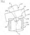
- the forming head 201 includes radially outwardly lying on its molding surface 207 integrally with the formed body 205 formed, substantially axially extending Umgreifpatented 225.
- the inner dimension of the Umgreif gleich 225 substantially corresponds to the outer dimension the sleeve 213 in the undeformed state.
- the starting piece 209 of the Fromkopfes 201 prevents deformation of the end portion over a desired Measure radially inward.
- a sleeve 213 with a radially inwardly projecting collar formed, wherein the outer side 227 of the sleeve 213 in the longitudinal direction continuously in extending lying a cylindrical plane.
- the mold surface 7 of the forming head 1 is shown in a plan view, the at the forming method of Figure 1 is used. From Figure 4 is the rotationally shaped Design of the forming head 1 to the rotation axis R visible, with the extension piece 9 and the wedge-shaped projection 15 concentrically extend around the rotation axis R.
- the mold surface 207 of the forming head 201 is shown in a plan view, the is used according to the forming method of Figure 3. From Figure 5, the rotationally Embodiment of the forming head 201 can be seen, the approach 209 and the Umgreifpatented 225 are formed concentrically about the axis of rotation R.
- the designs of the forming surface 7, 207 illustrates the operating principle of the forming process according to the invention in that the substantially flat molding surface 7, 207 with the wedge-shaped projection 15 and the Umgreifpatented 225 cooperates in such a way that on the one hand, the sleeve body concentrated A localized point is reshaped, but distributed along a force introduction line radially along the forming surface 7, 207, and on the other hand, the wedge-shaped projection 15 or the Umgreifpatented 225 lead the forming force to be introduced in the desired direction, in which is to deform the sleeve material to form the desired end portion.
Landscapes
- Engineering & Computer Science (AREA)
- Mechanical Engineering (AREA)
- General Engineering & Computer Science (AREA)
- Manufacturing & Machinery (AREA)
- Springs (AREA)
- Dowels (AREA)
- Protection Of Pipes Against Damage, Friction, And Corrosion (AREA)
- Pivots And Pivotal Connections (AREA)
Abstract
Description
- Figur 1
- eine Querschnittsansicht zweier Werkzeug-Hülsen-Anordnungen zur Durchführung des erfindungsgemäßen Verfahrens zum Umformen eines Endbereichs einer Hülse, wobei eine erste Ausführung mit der zeichnerisch linken Hälfte der Anordnung und eine zweite Ausführung mit der zeichnerisch rechten Hälfte der Anordnung dargestellt sein sollen.
- Figur 2
- eine Querschnittsansicht eines Endbereichs einer gemäß der Ausführung des Verfahrens mit der linken Anordnung nach Figur 1 umgeformten Hülse;
- Figur 3
- eine Querschnittsansicht einer Werkzeug-Hülsen-Anordnung gemäß einer weiteren Ausführung des erfindungsgemäßen Umformverfahrens;
- Figur 4
- eine Draufsicht auf eine Formseite eines erfindungsgemäßen Formwerkzeugs in einer ersten Ausführung;
- Figur 5
- eine Draufsicht auf eine Formseite eines erfindungsgemäßen Formwerkzeugs in einer zweiten Ausführung.
- 1,201
- Formkopf
- 3
- Antriebswelle
- 5,205
- Formkörper
- 7,207
- Formfläche
- 9, 209
- Ansatzstück oder Ansatz
- 10a, 10b, 110a, 110b
- Abstützarm
- 11, 111, 211
- Endbereich
- 12
- Basis
- 13,113,213
- Hülse
- 14
- Hülsenkörper
- 15, 15a, 15b
- keilförmiger Vorsprung
- 17
- gerundete Spitze
- 19,119,219
- Abstützfläche
- 21, 121
- Kerbe oder Einkerbung
- 225
- Umgreifstruktur
- 227
- Außenseite der Hülse
- α
- Winkel
- β
- Öffnungswinkel
- β1, β2
- V-Schenkel-Winkel
- D
- Durchmesser
- L
- Längsachse
- N
- Mediandurchmesser
- R
- Rotationsachse
- T
- Normale
- n
- Nenndicke
- r
- Radius
Claims (35)
- Verfahren zum Umformen eines Endbereichs (11, 111, 211) einer starren Hülse (13, 113, 213) eines elastischen Gelenks, wobei ein Formwerkzeug zum Aufbringen einer Umformkraft an dem Endbereich (11, 111, 211) angesetzt und um eine gegenüber einer Axialrichtung der Hülse geneigte Rotationsachse (R) auf dem Endbereich (11, 111, 211) abrollend gedreht wird derart, daß der Endbereich (11, 111, 211) in Radialrichtung der Hülse (13, 113, 213) verformt wird,
dadurch gekennzeichnet, daß zumindest ein nicht vernachlässigbarer Teil der Umformkraft in den Endbereich (11, 111, 211) mit zumindest einer radial nach innen weisenden Richtungskomponente eingeleitet wird. - Verfahren nach Anspruch 1, dadurch gekennzeichnet, daß der nicht vernachlässigbare Teil der Umformkraft derart eingeleitet wird, daß der Endbereich (11, 111, 211) zumindest teilweise nach radial innen, vorzugsweise radial nach außen und innen, verformt wird, insbesondere über die radiale Abmessung des unverformten Endbereichs hinaus.
- Verfahren nach einem der vorangegangenen Ansprüche, dadurch gekennzeichnet, daß der Endbereich (11, 111) während eines Umformschritts radial nach außen und radial nach innen in einem vorab bestimmten Verformungsverhältnis verformt wird.
- Verfahren nach Anspruch 3, dadurch gekennzeichnet, daß ein Verhältnis von radial äußerer und radial innerer Formung eingestellt wird.
- Verfahren nach einem der vorangegangenen Ansprüche, dadurch gekennzeichnet, daß der Umformschritt frei von einer eine Verformung des Endbereichs (11, 111, 211) nach radial innen und/oder außen einschränkenden Matrize durchgeführt wird.
- Verfahren nach einem der vorangegangenen Ansprüche, dadurch gekennzeichnet, daß eine Verformung des Endbereichs (11, 111) radial nach außen zumindest begrenzt und vorzugsweise vollständig verhindert wird.
- Verfahren nach einem der vorangegangenen Ansprüche, dadurch gekennzeichnet, daß eine dem Formwerkzeug zuzuwendende Fläche des Endbereichs (11, 111) beim abrollenden Umformen durch das Formwerkzeug aufgespreizt oder aufgespalten wird.
- Verfahren nach Anspruch 8, dadurch gekennzeichnet, daß eine vorbestimmbare, radial nach außen und/oder radial nach innen weisende Spreizrichtungskomponente hervorgerufen wird.
- Verfahren nach Anspruch 7 oder 8, dadurch gekennzeichnet, daß die Größe einer Spreizrichtungskomponente abhängig von dem gewünschten Verformungsmaß eingestellt wird.
- Rotationsförmiges Werkzeug zum Umformen eines Endbereichs (11, 111, 211) einer starren Hülse (13, 113, 213) eines elastischen Gelenks, umfassend einen Formkörper mit einer Formfläche, über die dem Endbereich (11, 111, 211) abrollend eine Umformkraft mitteilbar ist, gekennzeichnet durch eine Einrichtung zum gerichteten Einleiten der Umformkraft in den Endbereich (11, 111, 211) mit zumindest einer nicht vernachlässigbaren, radial nach innen bezüglich der Rotationsachse (R) des Werkzeugs weisenden Richtungskomponente.
- Werkzeug nach Anspruch 10, dadurch gekennzeichnet, daß die Einrichtung an der Formfläche angeordnet ist.
- Werkzeug nach Anspruch 10 oder 11, dadurch gekennzeichnet, daß die Einrichtung dazu ausgelegt ist, die Umformkraft in den Endbereich mit zumindest einer nicht vernachlässigbaren, hin zur Rotationsachse (R) und von der Rotationsachse (R) wegweisenden Richtungskomponente gerichtet einzuleiten.
- Werkzeug nach einem der Ansprüche 10 bis 12, dadurch gekennzeichnet, daß die Einrichtung als Aufspreiz- oder Aufspaltstruktur ausgeführt ist.
- Werkzeug nach Anspruch 13, dadurch gekennzeichnet, daß ein Spreizwinkel zum Einstellen der Richtungskomponente der Umformkraft wählbar ist.
- Werkzeug nach einem der Ansprüche 10 bis 14, dadurch gekennzeichnet, daß Einrichtung und der Formkörper aus einem Stück gefertigt sind.
- Werkzeug nach einem der Ansprüche 10 bis 15, dadurch gekennzeichnet, daß die Einrichtung als ein sich von der Formfläche erstreckender keilförmiger oder V-förmiger Vorsprung (15, 15a, 15b) ausgebildet ist, wobei insbesondere die Spitze des Vorsprungs (15b) gerundet ist.
- Werkzeug nach einem der Ansprüche 10 bis 16, dadurch gekennzeichnet, daß sich die Einrichtung konzentrisch um die Rotationsachse erstreckt.
- Werkzeug nach Anspruch 17, dadurch gekennzeichnet, daß der Durchmesser der konzentrischen Einrichtung zum Einstellen der Richtungskomponente der Umformkraft auswählbar ist.
- Werkzeug nach einem der Ansprüche 10 bis 16, dadurch gekennzeichnet, daß die Einrichtung für bestimmte Umformkraft-Einleitrichtungen hin zur Rotationsachse oder von dieser weg einstellbar ist.
- Werkzeug nach einem der Ansprüche 10 bis 19, dadurch gekennzeichnet, daß die Einrichtung ein Umgreifstruktur aufweist, die dazu ausgelegt ist, die Außenseite des Endbereichs der Hülse zu umgreifen.
- Werkzeug nach Anspruch 20, dadurch gekennzeichnet, daß die Umgreifstruktur eine Innenabmessung aufweist, die im wesentlichen einer äußeren Abmessung des Endbereichs der Hülse entspricht, vorzugsweise mit einem geringen Übermaß zur Außenabmessung des unverformten Endbereichs ausgebildet ist.
- Werkzeug nach einem der Ansprüche 10 bis 21, gekennzeichnet durch einen Umformbegrenzer, der eine Umformung des Endbereichs (11, 111, 211) der Hülse (13, 113, 213) radial nach innen begrenzt.
- Werkzeug nach Anspruch 22, dadurch gekennzeichnet, daß der Umformbegrenzer durch einen konzentrisch um die Rotationsachse (R), sich von der Formfläche erstreckenden Ansatz ausgebildet ist.
- Elastisches Gelenk mit einer Längsachse, einer radial innenliegenden und/oder einer radial außenliegenden Hülse und einem zumindest mit einer Hülse verbundenen Elastomerkörper, wobei die Hülse mindestens einen Endbereich mit einer Abstützfläche aufweist, der mit einer radialen Überdicke ausgebildet ist, dadurch gekennzeichnet, daß zur Bildung einer Überdicke der Hülse (13, 113) im Bereich der Abstützfläche der Endbereich (11, 111) durch eine in die Abstützfläche eingebrachte Einkerbung (21, 121) derart verformt ist, daß zumindest einer der der Einkerbung (21, 121) benachbarten Flankenabschnitte radial über eine Nenndickenabmessung der Hülse verlagert ist.
- Elastisches Gelenk nach Anspruch 24, dadurch gekennzeichnet, daß an der Abstützfläche wenigstens eine Einkerbung (21, 121) derart eingebracht ist, daß der überdicke Endbereich im wesentlichen gemäß dem radialen Maß der Einkerbung (21, 121) über die Nenndickenabmessung der Hülse (13, 113) hinaus radial geweitet ist.
- Elastisches Gelenk nach Anspruch 24 oder 25, dadurch gekennzeichnet, daß sich die Einkerbung (21, 121) zumindest kreisabschnittsweise im wesentlichen konzentrisch, insbesondere im wesentlichen kreisförmig, um die Längsachse erstreckt.
- Elastisches Gelenk nach einem der Ansprüche 1 bis 26, dadurch gekennzeichnet, daß die Einkerbung V-förmig ist, wobei insbesondere die Senke der Einkerbung gerundet ist.
- Elastisches Gelenk nach Anspruch 27, dadurch gekennzeichnet, daß ein Öffnungswinkel der V-förmigen Einkerbung zwischen ca. 15° bis ca. 120°, vorzugsweise 30° bis 90°, liegt.
- Elastisches Gelenk nach einem der Ansprüche 25 bis 28, dadurch gekennzeichnet, daß die Einkerbung (21, 121) einen ersten V-Schenkel-Winkel und einen zweiten V-Schenkel-Winkel aufweist, die vorzugsweise unterschiedlich oder gleich groß sind.
- Elastisches Gelenk nach einem der Ansprüche 25 bis 29, dadurch gekennzeichnet, daß die Tiefe der Einkerbung (21, 121) zwischen ca. 0,5 mm und 3 mm liegt.
- Elastisches Gelenk nach einem der Ansprüche 25 bis 30, dadurch gekennzeichnet, daß die Einkerbung (21, 121) im wesentlichen auf Höhe eines Mediandurchmessers (N) der Hülse (13, 113) angeordnet ist.
- Elastisches Gelenk nach einem der Ansprüche 25 bis 30, dadurch gekennzeichnet, daß die Einkerbung (21, 121) von einem Mediandurchmesser (N) der Hülse (13, 113) versetzt angeordnet ist.
- Elastisches Gelenk mit einer Längsachse, einer radial innenliegenden und/oder einer radial außenliegenden Hülse und einem mit zumindest einer der Hülsen verbundenen Elastomerkörper, wobei die Hülse (213) zwei Endbereiche und einen die Endbereiche einstückig verbindenden Hülsenkörper aufweist und mindestens einer (211) der Endbereiche mit einer im wesentlichen radial nach innen ragenden Überdickung ausgebildet ist, dadurch gekennzeichnet, daß die Außenseite des überdicken Endbereichs (211), eines Übergangsbereichs von dem Endbereich zum Hülsenkörper und zumindest eines dem Übergangsbereich benachbarten Abschnitts des Hülsenkörpers (14) im wesentlichen in einer zur Längsachse konzentrischen Ebene liegt.
- Elastisches Gelenk nach Anspruch 33, dadurch gekennzeichnet, daß die gesamte Außenseite der Hülse (213) im wesentlichen eben und stufenfrei ist.
- Elastisches Gelenk nach Anspruch 33 oder 34, dadurch gekennzeichnet, daß es nach einem der Ansprüche 24 bis 32 ausgebildet ist.
Priority Applications (6)
| Application Number | Priority Date | Filing Date | Title |
|---|---|---|---|
| ES04290404T ES2294443T3 (es) | 2004-02-13 | 2004-02-13 | Procedimiento de transformacion de una zona extrema de un casquillo rigido, util de transformacion y articulacion elastica. |
| EP04290404A EP1563927B1 (de) | 2004-02-13 | 2004-02-13 | Verfahren zum Umformen eines Endbereichs einer starren Hülse, Werkzeug zum Umformen und elastische Gelenke |
| DE502004005427T DE502004005427D1 (de) | 2004-02-13 | 2004-02-13 | Verfahren zum Umformen eines Endbereichs einer starren Hülse, Werkzeug zum Umformen und elastische Gelenke |
| ES07007708.6T ES2655866T3 (es) | 2004-02-13 | 2004-02-13 | Útil para la transformación de una zona extrema de un casquillo rígido y articulación elástica |
| AT04290404T ATE377468T1 (de) | 2004-02-13 | 2004-02-13 | Verfahren zum umformen eines endbereichs einer starren hülse, werkzeug zum umformen und elastische gelenke |
| EP07007708.6A EP1818118B1 (de) | 2004-02-13 | 2004-02-13 | Werkzeug zum Umformen eines Endbereichs einer starren Hülse und elastische Gelenke |
Applications Claiming Priority (1)
| Application Number | Priority Date | Filing Date | Title |
|---|---|---|---|
| EP04290404A EP1563927B1 (de) | 2004-02-13 | 2004-02-13 | Verfahren zum Umformen eines Endbereichs einer starren Hülse, Werkzeug zum Umformen und elastische Gelenke |
Related Child Applications (1)
| Application Number | Title | Priority Date | Filing Date |
|---|---|---|---|
| EP07007708.6A Division EP1818118B1 (de) | 2004-02-13 | 2004-02-13 | Werkzeug zum Umformen eines Endbereichs einer starren Hülse und elastische Gelenke |
Publications (2)
| Publication Number | Publication Date |
|---|---|
| EP1563927A1 true EP1563927A1 (de) | 2005-08-17 |
| EP1563927B1 EP1563927B1 (de) | 2007-11-07 |
Family
ID=34684784
Family Applications (2)
| Application Number | Title | Priority Date | Filing Date |
|---|---|---|---|
| EP04290404A Expired - Lifetime EP1563927B1 (de) | 2004-02-13 | 2004-02-13 | Verfahren zum Umformen eines Endbereichs einer starren Hülse, Werkzeug zum Umformen und elastische Gelenke |
| EP07007708.6A Expired - Lifetime EP1818118B1 (de) | 2004-02-13 | 2004-02-13 | Werkzeug zum Umformen eines Endbereichs einer starren Hülse und elastische Gelenke |
Family Applications After (1)
| Application Number | Title | Priority Date | Filing Date |
|---|---|---|---|
| EP07007708.6A Expired - Lifetime EP1818118B1 (de) | 2004-02-13 | 2004-02-13 | Werkzeug zum Umformen eines Endbereichs einer starren Hülse und elastische Gelenke |
Country Status (4)
| Country | Link |
|---|---|
| EP (2) | EP1563927B1 (de) |
| AT (1) | ATE377468T1 (de) |
| DE (1) | DE502004005427D1 (de) |
| ES (2) | ES2655866T3 (de) |
Cited By (2)
| Publication number | Priority date | Publication date | Assignee | Title |
|---|---|---|---|---|
| WO2018172145A1 (de) * | 2017-03-22 | 2018-09-27 | Vibracoustic Gmbh | Kern für ein elastisches lager, elastisches lager mit einem derartigen kern sowie verfahren zur herstellung eines derartigen kerns |
| DE102022204038A1 (de) | 2022-04-26 | 2023-10-26 | Volkswagen Aktiengesellschaft | Vorrichtung und Verfahren zum Umformen eines hohlzylindrischen, metallischen Endabschnitts eines Werkstücks |
Citations (7)
| Publication number | Priority date | Publication date | Assignee | Title |
|---|---|---|---|---|
| EP0250272A2 (de) * | 1986-06-20 | 1987-12-23 | Iracroft Limited | Verfahren zum Herstellen einer Seitenflächendichtung |
| EP0524844B1 (de) * | 1991-07-23 | 1995-05-03 | Caoutchouc Manufacture Et Plastiques | Verfahren zum Bilden einer Überdicke an den Enden des Innenrohrs eines Gelenks nach dem Formen und dessen Anwendungen |
| US5806166A (en) * | 1994-02-04 | 1998-09-15 | Parker Hannifin Rak Sa | Connecting device for an end of a rigid metallic pipe for conveying a fluid |
| US6370776B1 (en) * | 1999-04-14 | 2002-04-16 | Kanemitsu Corporation | Method of producing a poly-V pulley |
| EP1219853A2 (de) * | 2000-12-25 | 2002-07-03 | TOYO TIRE & RUBBER CO., LTD . | Verfahren zur Herstellung einer schwingungsdämpfenden Buchse |
| WO2002070170A1 (fr) * | 2001-03-06 | 2002-09-12 | Michelin Avs S.A.S. | Procédé de bouterollage d'une douille, notamment d'une douille formant une articulation élastique et douille et articulation élastiques obtenues selon ce procédé |
| EP1386677A1 (de) * | 2001-04-19 | 2004-02-04 | Toyo Tire & Rubber Co., Ltd . | Verfahren und bearbeitung eines endteils eines metallischen rohrkörpers und metallischer rohrkörper, und verfahren zur herstellung einer erschütterungssicheren buchse unter verwendung des bearbeitungsverfahrens und erschütterungssichere buchse |
Family Cites Families (1)
| Publication number | Priority date | Publication date | Assignee | Title |
|---|---|---|---|---|
| US5814421A (en) * | 1996-12-20 | 1998-09-29 | Tulip Corporation | Method and apparatus for making a battery terminal and a battery terminal made thereby |
-
2004
- 2004-02-13 DE DE502004005427T patent/DE502004005427D1/de not_active Expired - Lifetime
- 2004-02-13 ES ES07007708.6T patent/ES2655866T3/es not_active Expired - Lifetime
- 2004-02-13 EP EP04290404A patent/EP1563927B1/de not_active Expired - Lifetime
- 2004-02-13 EP EP07007708.6A patent/EP1818118B1/de not_active Expired - Lifetime
- 2004-02-13 AT AT04290404T patent/ATE377468T1/de not_active IP Right Cessation
- 2004-02-13 ES ES04290404T patent/ES2294443T3/es not_active Expired - Lifetime
Patent Citations (7)
| Publication number | Priority date | Publication date | Assignee | Title |
|---|---|---|---|---|
| EP0250272A2 (de) * | 1986-06-20 | 1987-12-23 | Iracroft Limited | Verfahren zum Herstellen einer Seitenflächendichtung |
| EP0524844B1 (de) * | 1991-07-23 | 1995-05-03 | Caoutchouc Manufacture Et Plastiques | Verfahren zum Bilden einer Überdicke an den Enden des Innenrohrs eines Gelenks nach dem Formen und dessen Anwendungen |
| US5806166A (en) * | 1994-02-04 | 1998-09-15 | Parker Hannifin Rak Sa | Connecting device for an end of a rigid metallic pipe for conveying a fluid |
| US6370776B1 (en) * | 1999-04-14 | 2002-04-16 | Kanemitsu Corporation | Method of producing a poly-V pulley |
| EP1219853A2 (de) * | 2000-12-25 | 2002-07-03 | TOYO TIRE & RUBBER CO., LTD . | Verfahren zur Herstellung einer schwingungsdämpfenden Buchse |
| WO2002070170A1 (fr) * | 2001-03-06 | 2002-09-12 | Michelin Avs S.A.S. | Procédé de bouterollage d'une douille, notamment d'une douille formant une articulation élastique et douille et articulation élastiques obtenues selon ce procédé |
| EP1386677A1 (de) * | 2001-04-19 | 2004-02-04 | Toyo Tire & Rubber Co., Ltd . | Verfahren und bearbeitung eines endteils eines metallischen rohrkörpers und metallischer rohrkörper, und verfahren zur herstellung einer erschütterungssicheren buchse unter verwendung des bearbeitungsverfahrens und erschütterungssichere buchse |
Cited By (2)
| Publication number | Priority date | Publication date | Assignee | Title |
|---|---|---|---|---|
| WO2018172145A1 (de) * | 2017-03-22 | 2018-09-27 | Vibracoustic Gmbh | Kern für ein elastisches lager, elastisches lager mit einem derartigen kern sowie verfahren zur herstellung eines derartigen kerns |
| DE102022204038A1 (de) | 2022-04-26 | 2023-10-26 | Volkswagen Aktiengesellschaft | Vorrichtung und Verfahren zum Umformen eines hohlzylindrischen, metallischen Endabschnitts eines Werkstücks |
Also Published As
| Publication number | Publication date |
|---|---|
| EP1563927B1 (de) | 2007-11-07 |
| EP1818118A3 (de) | 2007-08-22 |
| DE502004005427D1 (de) | 2007-12-20 |
| EP1818118A2 (de) | 2007-08-15 |
| ES2294443T3 (es) | 2008-04-01 |
| ATE377468T1 (de) | 2007-11-15 |
| ES2655866T3 (es) | 2018-02-22 |
| EP1818118B1 (de) | 2017-10-18 |
Similar Documents
| Publication | Publication Date | Title |
|---|---|---|
| EP2975286B1 (de) | Rückstellfeder | |
| EP2490923B1 (de) | Scheibenwischervorrichtung | |
| DE102016204619B4 (de) | Einpressverbindung zwischen einem hochfesten Bauteil und einem Einpresselement, Verfahren zur Ausbildung einer solchen Einpressverbindung sowie Einpresselement für eine solche Einpressverbindung | |
| EP2467231A1 (de) | Verfahren zur herstellung eines einen abschnitt einer lenkspindel bildenden lenkspindelteils | |
| EP2181783B1 (de) | Stange und Verfahren zu ihrer Herstellung | |
| EP1736681A1 (de) | Buchsenlager mit radialem und/oder axialem Anschlag und Verfahren zur Erzeugung eines Axialanschlags bei einem Buchsenlager | |
| EP0627568A1 (de) | Presspassverbindungselement, insbesondere Radbolzen | |
| DE69501672T2 (de) | Blindniete | |
| EP2934984B1 (de) | Lenksäule für ein kraftfahrzeug | |
| DE10050777B4 (de) | Luftfeder und Verfahren zur Herstellung einer Luftfeder | |
| WO2011018194A1 (de) | Nietverbindung und verfahren zu deren erzeugung | |
| DE60108061T2 (de) | Verfahren zur Herstellung einer schwingungsdämpfenden Buchse | |
| DE202017105715U1 (de) | Einpressverbindung zwischen einem hochfesten Bauteil und einem Einpresselement sowie Einpresselement für eine solche Einpressverbindung | |
| EP4378718B1 (de) | Verfahren zur herstellung eines fahrwerkbauteils | |
| EP3615265A1 (de) | Einpress-verbindungselement und verfahren zum verankern von einpress-verbindungselementen in ein bleibend verformbares metallisches flachmaterial oder daraus hergestellte bauteile bzw. werkstücke | |
| DE102015206461A1 (de) | Verfahren zur Umformung eines rohrförmigen Strukturbauteils für Kraftfahrzeugsitze | |
| EP2446980B1 (de) | Gerüstrohr und Verfahren zur Bearbeitung von Rohrenden | |
| DE102009025525A1 (de) | Verfahren zum Ausbilden einer Einpressverbindung zwischen einem Fügeelement und einem Werkstück, Einpressverbindung sowie Fügeelement | |
| EP1818118B1 (de) | Werkzeug zum Umformen eines Endbereichs einer starren Hülse und elastische Gelenke | |
| DE60202360T2 (de) | Verfahren zum aufweiten einer buchse, insbesondere eine buchse eines elastischen gelenkes, sowie dadurch erhaltene buchse und elastisches gelenk | |
| DE102017129187B4 (de) | Pressbauteil für die Ausbildung eines Presseverbundes mit einem Gegen-Pressbauteil | |
| EP3803138B1 (de) | Konusbolzen und verfahren zur herstellung eines konusbolzens | |
| DE10049048C1 (de) | Verfahren zum Herstellen von Enden für Hohlwellen | |
| DE102009002078A1 (de) | Verbindungsvorrichtung | |
| EP3473871B1 (de) | Verfahren zum setzen eines blindnietelements zum versteifen von zwei beabstandet angeordneten abschnitten zweier bauteile oder eines bauteils |
Legal Events
| Date | Code | Title | Description |
|---|---|---|---|
| PUAI | Public reference made under article 153(3) epc to a published international application that has entered the european phase |
Free format text: ORIGINAL CODE: 0009012 |
|
| AK | Designated contracting states |
Kind code of ref document: A1 Designated state(s): AT BE BG CH CY CZ DE DK EE ES FI FR GB GR HU IE IT LI LU MC NL PT RO SE SI SK TR |
|
| AX | Request for extension of the european patent |
Extension state: AL LT LV MK |
|
| 17P | Request for examination filed |
Effective date: 20051216 |
|
| AKX | Designation fees paid |
Designated state(s): AT BE BG CH CY CZ DE DK EE ES FI FR GB GR HU IE IT LI LU MC NL PT RO SE SI SK TR |
|
| GRAP | Despatch of communication of intention to grant a patent |
Free format text: ORIGINAL CODE: EPIDOSNIGR1 |
|
| GRAS | Grant fee paid |
Free format text: ORIGINAL CODE: EPIDOSNIGR3 |
|
| GRAA | (expected) grant |
Free format text: ORIGINAL CODE: 0009210 |
|
| AK | Designated contracting states |
Kind code of ref document: B1 Designated state(s): AT BE BG CH CY CZ DE DK EE ES FI FR GB GR HU IE IT LI LU MC NL PT RO SE SI SK TR |
|
| REG | Reference to a national code |
Ref country code: GB Ref legal event code: FG4D Free format text: NOT ENGLISH |
|
| REG | Reference to a national code |
Ref country code: IE Ref legal event code: FG4D Free format text: LANGUAGE OF EP DOCUMENT: GERMAN |
|
| REG | Reference to a national code |
Ref country code: CH Ref legal event code: EP |
|
| REF | Corresponds to: |
Ref document number: 502004005427 Country of ref document: DE Date of ref document: 20071220 Kind code of ref document: P |
|
| REG | Reference to a national code |
Ref country code: RO Ref legal event code: EPE |
|
| REG | Reference to a national code |
Ref country code: ES Ref legal event code: FG2A Ref document number: 2294443 Country of ref document: ES Kind code of ref document: T3 |
|
| PG25 | Lapsed in a contracting state [announced via postgrant information from national office to epo] |
Ref country code: NL Free format text: LAPSE BECAUSE OF FAILURE TO SUBMIT A TRANSLATION OF THE DESCRIPTION OR TO PAY THE FEE WITHIN THE PRESCRIBED TIME-LIMIT Effective date: 20071107 Ref country code: SE Free format text: LAPSE BECAUSE OF FAILURE TO SUBMIT A TRANSLATION OF THE DESCRIPTION OR TO PAY THE FEE WITHIN THE PRESCRIBED TIME-LIMIT Effective date: 20080207 |
|
| NLV1 | Nl: lapsed or annulled due to failure to fulfill the requirements of art. 29p and 29m of the patents act | ||
| PG25 | Lapsed in a contracting state [announced via postgrant information from national office to epo] |
Ref country code: SI Free format text: LAPSE BECAUSE OF FAILURE TO SUBMIT A TRANSLATION OF THE DESCRIPTION OR TO PAY THE FEE WITHIN THE PRESCRIBED TIME-LIMIT Effective date: 20071107 Ref country code: BG Free format text: LAPSE BECAUSE OF FAILURE TO SUBMIT A TRANSLATION OF THE DESCRIPTION OR TO PAY THE FEE WITHIN THE PRESCRIBED TIME-LIMIT Effective date: 20080207 |
|
| GBV | Gb: ep patent (uk) treated as always having been void in accordance with gb section 77(7)/1977 [no translation filed] | ||
| ET | Fr: translation filed | ||
| PG25 | Lapsed in a contracting state [announced via postgrant information from national office to epo] |
Ref country code: DK Free format text: LAPSE BECAUSE OF FAILURE TO SUBMIT A TRANSLATION OF THE DESCRIPTION OR TO PAY THE FEE WITHIN THE PRESCRIBED TIME-LIMIT Effective date: 20071107 Ref country code: CZ Free format text: LAPSE BECAUSE OF FAILURE TO SUBMIT A TRANSLATION OF THE DESCRIPTION OR TO PAY THE FEE WITHIN THE PRESCRIBED TIME-LIMIT Effective date: 20071107 |
|
| PG25 | Lapsed in a contracting state [announced via postgrant information from national office to epo] |
Ref country code: SK Free format text: LAPSE BECAUSE OF FAILURE TO SUBMIT A TRANSLATION OF THE DESCRIPTION OR TO PAY THE FEE WITHIN THE PRESCRIBED TIME-LIMIT Effective date: 20071107 |
|
| BERE | Be: lapsed |
Owner name: MICHELIN AVS S.A.S. Effective date: 20080228 |
|
| PLBE | No opposition filed within time limit |
Free format text: ORIGINAL CODE: 0009261 |
|
| STAA | Information on the status of an ep patent application or granted ep patent |
Free format text: STATUS: NO OPPOSITION FILED WITHIN TIME LIMIT |
|
| PG25 | Lapsed in a contracting state [announced via postgrant information from national office to epo] |
Ref country code: PT Free format text: LAPSE BECAUSE OF FAILURE TO SUBMIT A TRANSLATION OF THE DESCRIPTION OR TO PAY THE FEE WITHIN THE PRESCRIBED TIME-LIMIT Effective date: 20080407 |
|
| REG | Reference to a national code |
Ref country code: CH Ref legal event code: PL |
|
| REG | Reference to a national code |
Ref country code: IE Ref legal event code: FD4D |
|
| 26N | No opposition filed |
Effective date: 20080808 |
|
| PG25 | Lapsed in a contracting state [announced via postgrant information from national office to epo] |
Ref country code: LI Free format text: LAPSE BECAUSE OF NON-PAYMENT OF DUE FEES Effective date: 20080229 Ref country code: IE Free format text: LAPSE BECAUSE OF FAILURE TO SUBMIT A TRANSLATION OF THE DESCRIPTION OR TO PAY THE FEE WITHIN THE PRESCRIBED TIME-LIMIT Effective date: 20071107 Ref country code: MC Free format text: LAPSE BECAUSE OF NON-PAYMENT OF DUE FEES Effective date: 20080228 Ref country code: CH Free format text: LAPSE BECAUSE OF NON-PAYMENT OF DUE FEES Effective date: 20080229 |
|
| PG25 | Lapsed in a contracting state [announced via postgrant information from national office to epo] |
Ref country code: GB Free format text: LAPSE BECAUSE OF FAILURE TO SUBMIT A TRANSLATION OF THE DESCRIPTION OR TO PAY THE FEE WITHIN THE PRESCRIBED TIME-LIMIT Effective date: 20071107 |
|
| PG25 | Lapsed in a contracting state [announced via postgrant information from national office to epo] |
Ref country code: EE Free format text: LAPSE BECAUSE OF FAILURE TO SUBMIT A TRANSLATION OF THE DESCRIPTION OR TO PAY THE FEE WITHIN THE PRESCRIBED TIME-LIMIT Effective date: 20071107 Ref country code: GR Free format text: LAPSE BECAUSE OF FAILURE TO SUBMIT A TRANSLATION OF THE DESCRIPTION OR TO PAY THE FEE WITHIN THE PRESCRIBED TIME-LIMIT Effective date: 20080208 |
|
| PG25 | Lapsed in a contracting state [announced via postgrant information from national office to epo] |
Ref country code: FI Free format text: LAPSE BECAUSE OF FAILURE TO SUBMIT A TRANSLATION OF THE DESCRIPTION OR TO PAY THE FEE WITHIN THE PRESCRIBED TIME-LIMIT Effective date: 20071107 Ref country code: BE Free format text: LAPSE BECAUSE OF NON-PAYMENT OF DUE FEES Effective date: 20080228 |
|
| PG25 | Lapsed in a contracting state [announced via postgrant information from national office to epo] |
Ref country code: AT Free format text: LAPSE BECAUSE OF NON-PAYMENT OF DUE FEES Effective date: 20080213 |
|
| PG25 | Lapsed in a contracting state [announced via postgrant information from national office to epo] |
Ref country code: CY Free format text: LAPSE BECAUSE OF FAILURE TO SUBMIT A TRANSLATION OF THE DESCRIPTION OR TO PAY THE FEE WITHIN THE PRESCRIBED TIME-LIMIT Effective date: 20071107 |
|
| PG25 | Lapsed in a contracting state [announced via postgrant information from national office to epo] |
Ref country code: LU Free format text: LAPSE BECAUSE OF NON-PAYMENT OF DUE FEES Effective date: 20080213 Ref country code: HU Free format text: LAPSE BECAUSE OF FAILURE TO SUBMIT A TRANSLATION OF THE DESCRIPTION OR TO PAY THE FEE WITHIN THE PRESCRIBED TIME-LIMIT Effective date: 20080508 |
|
| PG25 | Lapsed in a contracting state [announced via postgrant information from national office to epo] |
Ref country code: TR Free format text: LAPSE BECAUSE OF FAILURE TO SUBMIT A TRANSLATION OF THE DESCRIPTION OR TO PAY THE FEE WITHIN THE PRESCRIBED TIME-LIMIT Effective date: 20071107 |
|
| PG25 | Lapsed in a contracting state [announced via postgrant information from national office to epo] |
Ref country code: IT Free format text: LAPSE BECAUSE OF NON-PAYMENT OF DUE FEES Effective date: 20080229 |
|
| REG | Reference to a national code |
Ref country code: DE Ref legal event code: R084 Ref document number: 502004005427 Country of ref document: DE |
|
| REG | Reference to a national code |
Ref country code: FR Ref legal event code: PLFP Year of fee payment: 13 |
|
| REG | Reference to a national code |
Ref country code: FR Ref legal event code: PLFP Year of fee payment: 14 |
|
| REG | Reference to a national code |
Ref country code: FR Ref legal event code: PLFP Year of fee payment: 15 |
|
| PGFP | Annual fee paid to national office [announced via postgrant information from national office to epo] |
Ref country code: RO Payment date: 20190129 Year of fee payment: 16 Ref country code: ES Payment date: 20190320 Year of fee payment: 16 |
|
| PG25 | Lapsed in a contracting state [announced via postgrant information from national office to epo] |
Ref country code: RO Free format text: LAPSE BECAUSE OF NON-PAYMENT OF DUE FEES Effective date: 20200213 |
|
| REG | Reference to a national code |
Ref country code: ES Ref legal event code: FD2A Effective date: 20210705 |
|
| PG25 | Lapsed in a contracting state [announced via postgrant information from national office to epo] |
Ref country code: ES Free format text: LAPSE BECAUSE OF NON-PAYMENT OF DUE FEES Effective date: 20200214 |
|
| PGFP | Annual fee paid to national office [announced via postgrant information from national office to epo] |
Ref country code: FR Payment date: 20230220 Year of fee payment: 20 |
|
| PGFP | Annual fee paid to national office [announced via postgrant information from national office to epo] |
Ref country code: DE Payment date: 20230216 Year of fee payment: 20 |
|
| REG | Reference to a national code |
Ref country code: DE Ref legal event code: R071 Ref document number: 502004005427 Country of ref document: DE |