EP1563751B1 - Damping element for a shoe - Google Patents
Damping element for a shoe Download PDFInfo
- Publication number
- EP1563751B1 EP1563751B1 EP05010930A EP05010930A EP1563751B1 EP 1563751 B1 EP1563751 B1 EP 1563751B1 EP 05010930 A EP05010930 A EP 05010930A EP 05010930 A EP05010930 A EP 05010930A EP 1563751 B1 EP1563751 B1 EP 1563751B1
- Authority
- EP
- European Patent Office
- Prior art keywords
- damping element
- damping
- element according
- elements
- connecting portion
- Prior art date
- Legal status (The legal status is an assumption and is not a legal conclusion. Google has not performed a legal analysis and makes no representation as to the accuracy of the status listed.)
- Expired - Lifetime
Links
- 238000013016 damping Methods 0.000 title claims abstract description 96
- 238000007789 sealing Methods 0.000 claims description 18
- 239000004033 plastic Substances 0.000 claims description 9
- 229920003023 plastic Polymers 0.000 claims description 9
- 239000000463 material Substances 0.000 claims description 6
- -1 polyethylene Polymers 0.000 claims description 6
- 238000001746 injection moulding Methods 0.000 claims description 5
- 239000004952 Polyamide Substances 0.000 claims description 2
- 239000004698 Polyethylene Substances 0.000 claims description 2
- 239000004743 Polypropylene Substances 0.000 claims description 2
- 239000000203 mixture Substances 0.000 claims description 2
- 229920002647 polyamide Polymers 0.000 claims description 2
- 229920000573 polyethylene Polymers 0.000 claims description 2
- 229920001155 polypropylene Polymers 0.000 claims description 2
- 229920002635 polyurethane Polymers 0.000 claims description 2
- 239000004814 polyurethane Substances 0.000 claims description 2
- 239000012815 thermoplastic material Substances 0.000 claims description 2
- 238000010521 absorption reaction Methods 0.000 abstract 1
- 238000011084 recovery Methods 0.000 description 4
- 239000011888 foil Substances 0.000 description 3
- 210000004027 cell Anatomy 0.000 description 2
- 230000000694 effects Effects 0.000 description 2
- 230000004308 accommodation Effects 0.000 description 1
- 230000006978 adaptation Effects 0.000 description 1
- 210000002421 cell wall Anatomy 0.000 description 1
- 230000006835 compression Effects 0.000 description 1
- 238000007906 compression Methods 0.000 description 1
- 239000013013 elastic material Substances 0.000 description 1
- 230000002349 favourable effect Effects 0.000 description 1
- 238000011065 in-situ storage Methods 0.000 description 1
- 230000000977 initiatory effect Effects 0.000 description 1
- 238000004519 manufacturing process Methods 0.000 description 1
- 239000000243 solution Substances 0.000 description 1
Images

Classifications
-
- A—HUMAN NECESSITIES
- A43—FOOTWEAR
- A43B—CHARACTERISTIC FEATURES OF FOOTWEAR; PARTS OF FOOTWEAR
- A43B13/00—Soles; Sole-and-heel integral units
- A43B13/14—Soles; Sole-and-heel integral units characterised by the constructive form
- A43B13/18—Resilient soles
- A43B13/181—Resiliency achieved by the structure of the sole
-
- A—HUMAN NECESSITIES
- A43—FOOTWEAR
- A43B—CHARACTERISTIC FEATURES OF FOOTWEAR; PARTS OF FOOTWEAR
- A43B13/00—Soles; Sole-and-heel integral units
- A43B13/14—Soles; Sole-and-heel integral units characterised by the constructive form
- A43B13/18—Resilient soles
- A43B13/20—Pneumatic soles filled with a compressible fluid, e.g. air, gas
- A43B13/206—Pneumatic soles filled with a compressible fluid, e.g. air, gas provided with tubes or pipes or tubular shaped cushioning members
-
- A—HUMAN NECESSITIES
- A43—FOOTWEAR
- A43B—CHARACTERISTIC FEATURES OF FOOTWEAR; PARTS OF FOOTWEAR
- A43B1/00—Footwear characterised by the material
- A43B1/0009—Footwear characterised by the material made at least partially of alveolar or honeycomb material
-
- A—HUMAN NECESSITIES
- A43—FOOTWEAR
- A43B—CHARACTERISTIC FEATURES OF FOOTWEAR; PARTS OF FOOTWEAR
- A43B1/00—Footwear characterised by the material
- A43B1/0072—Footwear characterised by the material made at least partially of transparent or translucent materials
-
- A—HUMAN NECESSITIES
- A43—FOOTWEAR
- A43B—CHARACTERISTIC FEATURES OF FOOTWEAR; PARTS OF FOOTWEAR
- A43B13/00—Soles; Sole-and-heel integral units
- A43B13/14—Soles; Sole-and-heel integral units characterised by the constructive form
- A43B13/18—Resilient soles
- A43B13/20—Pneumatic soles filled with a compressible fluid, e.g. air, gas
-
- A—HUMAN NECESSITIES
- A43—FOOTWEAR
- A43B—CHARACTERISTIC FEATURES OF FOOTWEAR; PARTS OF FOOTWEAR
- A43B7/00—Footwear with health or hygienic arrangements
- A43B7/32—Footwear with health or hygienic arrangements with shock-absorbing means
-
- Y—GENERAL TAGGING OF NEW TECHNOLOGICAL DEVELOPMENTS; GENERAL TAGGING OF CROSS-SECTIONAL TECHNOLOGIES SPANNING OVER SEVERAL SECTIONS OF THE IPC; TECHNICAL SUBJECTS COVERED BY FORMER USPC CROSS-REFERENCE ART COLLECTIONS [XRACs] AND DIGESTS
- Y10—TECHNICAL SUBJECTS COVERED BY FORMER USPC
- Y10T—TECHNICAL SUBJECTS COVERED BY FORMER US CLASSIFICATION
- Y10T428/00—Stock material or miscellaneous articles
- Y10T428/23—Sheet including cover or casing
- Y10T428/234—Sheet including cover or casing including elements cooperating to form cells
-
- Y—GENERAL TAGGING OF NEW TECHNOLOGICAL DEVELOPMENTS; GENERAL TAGGING OF CROSS-SECTIONAL TECHNOLOGIES SPANNING OVER SEVERAL SECTIONS OF THE IPC; TECHNICAL SUBJECTS COVERED BY FORMER USPC CROSS-REFERENCE ART COLLECTIONS [XRACs] AND DIGESTS
- Y10—TECHNICAL SUBJECTS COVERED BY FORMER USPC
- Y10T—TECHNICAL SUBJECTS COVERED BY FORMER US CLASSIFICATION
- Y10T428/00—Stock material or miscellaneous articles
- Y10T428/24—Structurally defined web or sheet [e.g., overall dimension, etc.]
- Y10T428/24149—Honeycomb-like
- Y10T428/24165—Hexagonally shaped cavities
-
- Y—GENERAL TAGGING OF NEW TECHNOLOGICAL DEVELOPMENTS; GENERAL TAGGING OF CROSS-SECTIONAL TECHNOLOGIES SPANNING OVER SEVERAL SECTIONS OF THE IPC; TECHNICAL SUBJECTS COVERED BY FORMER USPC CROSS-REFERENCE ART COLLECTIONS [XRACs] AND DIGESTS
- Y10—TECHNICAL SUBJECTS COVERED BY FORMER USPC
- Y10T—TECHNICAL SUBJECTS COVERED BY FORMER US CLASSIFICATION
- Y10T428/00—Stock material or miscellaneous articles
- Y10T428/24—Structurally defined web or sheet [e.g., overall dimension, etc.]
- Y10T428/24628—Nonplanar uniform thickness material
- Y10T428/24661—Forming, or cooperating to form cells
Definitions
- the invention relates to a damping element for a shoe, in particular for a sports shoe, according to the preamble of claim 1.
- a shoe which is equipped with a shoe sole, which already has a good damping behavior.
- the shoe is equipped with a shoe sole with at least one consisting of a honeycomb body made of elastic, compressible material insert part, wherein the central axes of the gas-filled honeycomb cells are approximately perpendicular to the sole plane.
- the honeycomb body is designed as a final shape in its dimensions, the honeycomb cells are sealed gas-tight at the periphery or at the edge of the honeycomb body.
- the preamble of claim 1 is known from US-A-4 521 979 and US-A-3 608 215.
- the invention is therefore based on the object , a damping element of the type mentioned in such a way that the damping behavior of the shoe is further improved.
- the restoring force of the shoe sole is to be increased after the pressure relief so that the energy recovery in the pressure relief of the shoe can be further increased.
- the damping element according to the invention is thus designed in the manner of a telescopic damper.
- the first element acts as a cylinder-like receiving chamber into which the second element can penetrate in the manner of a piston. This can be achieved a high travel and the spring and damping characteristics of the shoe can be adapted to the desired interests. Furthermore, there is also the possibility to recover the energy expended in the compression of the damping element to a considerable extent.
- the first element and the second element in a section perpendicular to the loading direction have a mutually corresponding shape. among them is to be understood that the cross-sectional geometry of the first and the second element are formed congruent to each other, so that a matching receiving and entry space is created in the first element for the second element.
- the first element and the second element have a polygonal, in particular hexagonal, shape in a section perpendicular to the loading direction.
- the damping element is designed in the manner of a honeycomb pattern.
- the dimensions of the first element in a section perpendicular to the loading direction are greater than the corresponding dimensions of the second element. This will allow the second element to enter the space defined by the first element.
- the first element is in the unloaded state of the damping element with its axial extent substantially outside the axial extent of the second element.
- the piston-like second element is arranged in the unloaded state of the damping element axially outside of the cylinder-like first element. Only when loading the damping element in the loading direction then enters the "piston" in the "cylinder".
- the first element and the second element are formed as hollow bodies, which are connected to each other via a connecting portion.
- the connecting section can in unloaded state of the damping element in a plane perpendicular to the loading direction run flat. Equally, however, it can also be provided that the connecting section runs curved in the unloaded state of the damping element. With the latter embodiment, the entry of the "piston” is favored in the "cylinder" under load. This is also the case when the connecting portion consists of elastic material, as provided according to another embodiment of the invention.
- first element, the connecting portion and the second element are integrally formed. It can be provided in particular that the first element and the second element are produced by an injection molding process. It is favorable if the first element, the connecting section and the second element are produced by a common injection molding process.
- the elements form gas-tight chambers.
- the second element facing away from the end of the first element is connected to a sealing film.
- the end facing away from the first element of the second element may be connected to a sealing film.
- the respective element and the sealing films can be gas-tightly connected to one another, in particular welded.
- the elements may be made of plastic, in particular of thermoplastic material.
- plastic polyethylene, polypropylene, polybutane, polyamide, polyurethane or a mixture of at least two of these plastics have proven.
- the plastic may be translucent or transparent.
- a multiplicity of first and / or second elements can be connected to one another or arranged next to one another.
- the first elements are connected to one another in their lateral region.
- Such an embodiment is particularly easy to implement in a geometry according to a honeycomb pattern.
- first and second elements are arranged next to one another, it can be provided that the connecting portion of at least two adjacent first and second elements is formed as a common part. It is also possible that the plurality of juxtaposed first and second elements are connected to each other via the connecting portions. A further development provides that the first and second elements are arranged at a distance and parallel to each other.
- damping element adaptation of the damping element to the specific needs in terms of geometry and function is facilitated by the fact that it can further be provided that the first and / or second elements at least partially in the unloaded state of the damping element have different heights.
- the damping characteristics, as well as the ability of the damping element to absorb and return energy can be influenced by the choice of parameters that determine the geometry and material properties.
- the material of the first element, of the second element and of the connecting section, as well as the geometric dimensions of said parts are selected for determining the rigidity of the damping element.
- a damping element which increases the damping and the restoring force of the shoe sole and thus the energy recovery after the pressure relief of the shoe sole to a large extent. Due to the proposed embodiments is also achieved that the damping element according to the invention can be manufactured inexpensively and thus inexpensive.
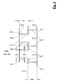
- a damping element 1 is shown in section.
- the damping element 1 is integrated in a shoe (not shown), in particular in the sole of a sports shoe. It serves to absorb energy when loading the sole in the loading direction R and to release the energy stored in the damping element 1 when the sole is relieved.
- the damping element 1 has a first element 2 and a second element 4, which are hexagonal in the manner of a honeycomb pattern.
- the first element 2 has a receiving space 3, which results from the volume of the hexagonal body.
- the extension of the first element 2 in the loading direction R is indicated by H (height of the first element 2 in the unloaded state of the damping element 1).
- H height of the first element 2 in the unloaded state of the damping element 1.
- the second element 4 is arranged, which extends over an axial height h in the loading direction R.
- the dimensions-width B of the first element 2 and width b of the second element 4- are selected such that the second element 4 can enter the receiving space 3 when the damping element 1 is loaded in the loading direction R, which is defined by the first element 2.
- the first element 2 and the second element 4 thus operate in the manner of a telescopic damper, wherein the first element 2 acts as a "cylinder", in which the second element 4 can enter in the manner of a "piston".
- the upper axial end region of the first element 2 to be seen in FIG. 1 and the axial lower end region of the second element 4 are connected to one another via a connecting section 5. It is at the connecting portion 5 - as well as the first and second elements 2, 4 - is a part of elastic plastic material, so that when a loading force on the damping element 1 in the loading direction R deformation takes place, as shown schematically in Fig. 3rd is shown.
- the second element 4 enters the receiving space 3 of the first element 2 like a piston.
- the second element 4 facing away from the end 6 of the first element 2 is connected to a first sealing film 7, in particular welded.
- the first element 2 facing away from the end 8 of the second element 4 is provided with a second sealing film 9.
- These sealing film 9 is also connected to the second element 4, preferably welded.
- the entire damping element 1 shown in FIG. 4 can be cut into a shoe and there, in particular, inserted into a midsole.
- the second elements 4 press more and more into the axial region of the first elements 2.
- the flat sealing foil 7 or 9 extends over a number of juxtaposed "piston-cylinder elements", ie a foil 7, 9 covers one Number of such elements.
- a foil 7, 9 covers one Number of such elements.
- This "lid” may be welded to the ends 6 and 8 of the elements 2 and 4, respectively; but it is also possible that it is injection-molded, for example, in injection molding of the elements 2 and 4, ie formed in situ with. It is preferably provided that the ends 6 of the first elements 2 are closed with a large-area film 7 (as shown in Fig. 1), while the ends 8 of the second elements 4 are closed only with individual film sections 9 in the form of "covers" ,
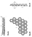
- FIGS. 6a, 6b, 6c and 7 show an alternative embodiment of the damping element.
- a plurality of first and second elements 2 and 4 are arranged side by side.
- the first and second elements 2 and 4 are positioned at a distance and parallel to one another (shown without films 7 or 9, see FIG. 1).
- connection of the individual units each consisting of a first and a second element 2 and 4, via the connecting portions 5, which also connect the first and the second element 2, 4 together.
- the connecting portions 5 thus provide not only the connection between the first and second elements 2, 4 - in the axial direction - but also the connection of the individual sub-elements to the structure shown in the said figures.
- first and second elements 2 and 4 at least partially in the illustrated unloaded state of the damping element different heights H and h (s., Fig. 1) exhibit.
- the spring and damping characteristics of the damping element 1 By adapting the geometry and in particular these heights and the widths of the individual elements 2 and 4, the thickness and design of the connecting portions 5 and also by appropriate choice of the material from which these parts are made, the spring and damping characteristics of the damping element 1 arbitrarily adapted or selected.
- the spring and damping characteristic of the damping element 1 - in particular the spring force on the spring travel - can thus be largely selected according to a desired course.
- the respective function which must fulfill the individual partial damping element consisting of the first element, the second element and the connecting section, can thus be influenced, ie. H. whether it is more of a support or a damping effect is needed.
- the damping element 1 according to the invention can also be used in combination with a conventional damping element, as is known in the art, in a shoe, in particular a sports shoe. This results in further possibilities to be able to optimally adapt the spring and damping behavior of a shoe, in particular a sports shoe, to the respective requirements.
Landscapes
- Health & Medical Sciences (AREA)
- Epidemiology (AREA)
- General Health & Medical Sciences (AREA)
- Public Health (AREA)
- Footwear And Its Accessory, Manufacturing Method And Apparatuses (AREA)
- Acyclic And Carbocyclic Compounds In Medicinal Compositions (AREA)
- Vibration Dampers (AREA)
- Electric Cable Installation (AREA)
- Springs (AREA)
- Laminated Bodies (AREA)
Abstract
Description
Die Erfindung betrifft ein Dämpfungselement für einen Schuh, insbesondere für einen Sportschuh, gemäß dem Oberbegriff des Anspruchs 1.The invention relates to a damping element for a shoe, in particular for a sports shoe, according to the preamble of
Aus der EP 0 387 505 B1 ist ein Schuh bekannt, der mit einer Schuhsohle ausgestattet ist, die bereits über ein gutes Dämpfungsverhalten verfügt. Zur Optimierung des Dämpfungsverhaltens und der Rückstellkraft der Schuhsohle nach deren Druckentlastung ist dort vorgesehen, dass der Schuh mit einer Schuhsohle mit mindestens einem aus einem Wabenkörper aus elastischem, kompressiblem Material bestehenden Einsatzteil ausgestattet ist, wobei die Zentralachsen der gasgefüllten Wabenzellen annähernd senkrecht zur Sohlenebene verlaufen. Der Wabenkörper ist als in seinen Abmessungen endgültiger Formkörper ausgebildet, wobei die Wabenzellen am Umfang bzw. am Rand des Wabenkörpers gasdicht verschlossen sind.From EP 0 387 505 B1 a shoe is known, which is equipped with a shoe sole, which already has a good damping behavior. To optimize the damping behavior and the restoring force of the shoe sole after the pressure relief is provided there that the shoe is equipped with a shoe sole with at least one consisting of a honeycomb body made of elastic, compressible material insert part, wherein the central axes of the gas-filled honeycomb cells are approximately perpendicular to the sole plane. The honeycomb body is designed as a final shape in its dimensions, the honeycomb cells are sealed gas-tight at the periphery or at the edge of the honeycomb body.
Mit einem derartigen Dämpfungselement in Form eines Wabenkörpers ist es bereits möglich, dem Schuh ein gutes Dämpfungsverhalten zu verleihen und die Rückstellkraft der Schuhsohle und damit den Energierückgewinn nach seiner Druckentlastung deutlich zu erhöhen. Eine weitere Steigerung dieser Parameter ist allerdings wünschenswert.With such a damping element in the form of a honeycomb body, it is already possible to give the shoe a good damping behavior and to significantly increase the restoring force of the shoe sole and thus the energy recovery after its pressure release. However, a further increase of these parameters is desirable.
Aus der DE 33 38 556 A1 ist weiterhin ein Dämpfungselement für einen Sportschuh der gattungsgemäßen Art bekannt, dessen Laufsohle mit Dämpfungsscheiben versehen ist, die jeweils aus einem Zylinder, in den austauschbare Dämpfungsscheiben eingelegt werden können, und aus einem jedem Zylinder zugeordneten Kolben besteht, der in den jeweiligen Zylinder eingreift und auf die Dämpfungsscheiben drückt.From DE 33 38 556 A1 discloses a damping element for a sports shoe of the generic type is known, the outsole is provided with damping discs, each of which consists of a cylinder, can be inserted into the interchangeable damping discs, and consists of a piston associated with each cylinder, the engages in the respective cylinder and presses on the damping discs.
Der Oberbegriff des Anspruchs 1 ist aus US-A-4 521 979 und US-A-3 608 215 bekannt.The preamble of
Der Erfindung liegt daher die Aufgabe zugrunde, ein Dämpfungselement der eingangs genannten Art derart weiterzubilden, dass das Dämpfungsverhalten des Schuhs weiter verbessert wird. Insbesondere soll die Rückstellkraft der Schuhsohle nach deren Druckentlastung so erhöht werden, dass die Energierückgewinnung bei der Druckentlastung des Schuhs noch weiter gesteigert werden kann.The invention is therefore based on the object , a damping element of the type mentioned in such a way that the damping behavior of the shoe is further improved. In particular, the restoring force of the shoe sole is to be increased after the pressure relief so that the energy recovery in the pressure relief of the shoe can be further increased.
Die Lösung dieser Aufgabe durch die Erfindung ist durch die Merkmale des Anspruchs 1 definiert.The solution of this problem by the invention is defined by the features of
Das erfindungsgemäße Dämpfungselement ist also nach Art eines Teleskop-Dämpfers ausgestaltet. Das erste Element fungiert als zylinderartige Aufnahmekammer, in die das zweite Element nach Art eines Kolbens eindringen kann. Damit kann ein hoher Federweg erreicht und die Feder- und Dämpfungscharakteristik des Schuhs an die gewünschten Belange angepasst werden. Weiterhin ergibt sich auch die Möglichkeit, die bei der Kompression des Dämpfungselements aufgewendete Energie in erheblichem Maße zurückzugewinnen.The damping element according to the invention is thus designed in the manner of a telescopic damper. The first element acts as a cylinder-like receiving chamber into which the second element can penetrate in the manner of a piston. This can be achieved a high travel and the spring and damping characteristics of the shoe can be adapted to the desired interests. Furthermore, there is also the possibility to recover the energy expended in the compression of the damping element to a considerable extent.
Gemäß der Erfindung ist vorgesehen, dass das erste Element und das zweite Element in einem Schnitt senkrecht zur Belastungsrichtung eine zueinander korrespondierende Form haben. Darunter ist zu verstehen, dass die Querschnittsgeometrie des ersten und des zweiten Elements zueinander kongruent ausgebildet sind, so dass ein passender Aufnahme- und Eintrittsraum im ersten Element für das zweite Element geschaffen wird.According to the invention it is provided that the first element and the second element in a section perpendicular to the loading direction have a mutually corresponding shape. among them is to be understood that the cross-sectional geometry of the first and the second element are formed congruent to each other, so that a matching receiving and entry space is created in the first element for the second element.
Das erste Element und das zweite Element haben in einem Schnitt senkrecht zur Belastungsrichtung eine mehreckige, insbesondere sechseckige, Gestalt. In diesem Falle ist das Dämpfungselement nach Art eines Wabenmusters ausgebildet.The first element and the second element have a polygonal, in particular hexagonal, shape in a section perpendicular to the loading direction. In this case, the damping element is designed in the manner of a honeycomb pattern.
Die Abmessungen des ersten Elements in einem Schnitt senkrecht zur Belastungsrichtung sind dabei größer als die entsprechenden Abmessungen des zweiten Elements. Hierdurch wird es ermöglicht, dass das zweite Element in den Raum eintreten kann, der durch das erste Element definiert ist.The dimensions of the first element in a section perpendicular to the loading direction are greater than the corresponding dimensions of the second element. This will allow the second element to enter the space defined by the first element.
Mit Vorteil befindet sich das erste Element im unbelasteten Zustand des Dämpfungselements mit seiner axialen Erstreckung im wesentlichen außerhalb der axialen Erstreckung des zweiten Elements. Darunter ist zu verstehen, dass das kolbenartige zweite Element im unbelasteten Zustand des Dämpfungselements axial außerhalb des zylinderartigen ersten Elements angeordnet ist. Erst bei Belastung des Dämpfungselements in Belastungsrichtung tritt dann der "Kolben" in den "Zylinder" ein.Advantageously, the first element is in the unloaded state of the damping element with its axial extent substantially outside the axial extent of the second element. This is to be understood that the piston-like second element is arranged in the unloaded state of the damping element axially outside of the cylinder-like first element. Only when loading the damping element in the loading direction then enters the "piston" in the "cylinder".
Das erste Element und das zweite Element sind als Hohlkörper ausgebildet, die über einen Verbindungsabschnitt miteinander verbunden sind. Der Verbindungsabschnitt kann im unbelasteten Zustand des Dämpfungselements in einer Ebene senkrecht zur Belastungsrichtung eben verlaufen. Genauso kann aber auch vorgesehen werden, dass der Verbindungsabschnitt im unbelasteten Zustand des Dämpfungselements gewölbt verläuft. Mit der letztgenannten Ausgestaltung wird das Eintreten des "Kolbens" in den "Zylinder" bei Belastung begünstigt. Dies ist auch der Fall, wenn der Verbindungsabschnitt aus elastischem Material besteht, wie es gemäß einer weiteren Fortbildung der Erfindung vorgesehen ist.The first element and the second element are formed as hollow bodies, which are connected to each other via a connecting portion. The connecting section can in unloaded state of the damping element in a plane perpendicular to the loading direction run flat. Equally, however, it can also be provided that the connecting section runs curved in the unloaded state of the damping element. With the latter embodiment, the entry of the "piston" is favored in the "cylinder" under load. This is also the case when the connecting portion consists of elastic material, as provided according to another embodiment of the invention.
Sowohl funktionale als auch fertigungstechnische Vorteile lassen sich erzielen, wenn das erste Element, der Verbindungsabschnitt und das zweite Element einstückig ausgebildet sind. Dabei kann insbesondere vorgesehen werden, dass das erste Element und das zweite Element durch einen Spritzgießprozess hergestellt sind. Günstig ist, wenn das erste Element, der Verbindungsabschnitt und das zweite Element durch einen gemeinsamen Spritzgießprozess hergestellt sind.Both functional and manufacturing advantages can be achieved if the first element, the connecting portion and the second element are integrally formed. It can be provided in particular that the first element and the second element are produced by an injection molding process. It is favorable if the first element, the connecting section and the second element are produced by a common injection molding process.
Zur Erzielung einer hohen Dämpfungs- und Energierückgewinnungseigenschaft des erfindungsgemäßen Dämpfungselements kann vorgesehen sein, dass die Elemente gasdichte Kammern bilden. Hierfür bietet sich an, dass das dem zweiten Element abgewandte Ende des ersten Elements mit einer Dichtfolie verbunden ist. Genauso kann das dem ersten Element abgewandte Ende des zweiten Elements mit einer Dichtfolie verbunden sein. Das jeweilige Element und die Dichtfolien können dabei gasdicht miteinander verbunden, insbesondere verschweißt sein. Mit einer solchen Ausgestaltung kann erreicht werden, dass das erste Element, das zweite Element, der Verbindungsabschnitt und die Dichtfolien eine gasdicht abgeschlossene flexible Kammer bilden. Dies beeinflusst die Wirkungsweise des erfindungsgemäßen Dämpfungselements in besonders vorteilhafter Weise.To achieve a high damping and energy recovery property of the damping element according to the invention can be provided that the elements form gas-tight chambers. For this purpose, it is advisable that the second element facing away from the end of the first element is connected to a sealing film. Likewise, the end facing away from the first element of the second element may be connected to a sealing film. The respective element and the sealing films can be gas-tightly connected to one another, in particular welded. With such a configuration can be achieved that the first element, the second element, the connecting portion and the sealing films form a gas-tightly sealed flexible chamber. This influences the mode of action of the damping element according to the invention in a particularly advantageous manner.
Die Elemente können aus Kunststoff, insbesondere aus thermoplastischem Material, bestehen. Als Kunststoff haben sich Polyäthylen, Polypropylen, Polybutan, Polyamid, Polyurethan oder eine Mischung von wenigstens zwei dieser Kunststoffe bewährt. Ferner kann der Kunststoff durchscheinend oder durchsichtig sein.The elements may be made of plastic, in particular of thermoplastic material. As a plastic polyethylene, polypropylene, polybutane, polyamide, polyurethane or a mixture of at least two of these plastics have proven. Furthermore, the plastic may be translucent or transparent.
Zur Ausbildung eines genügend großen Dämpfungselements, das die gewünschten Bereiche eines Schuhs, insbesondere eines Sportschuhs, bedeckt, können eine Vielzahl erster und/oder zweiter Elemente miteinander verbunden bzw. nebeneinander angeordnet sein.To form a sufficiently large damping element that covers the desired areas of a shoe, in particular a sports shoe, a multiplicity of first and / or second elements can be connected to one another or arranged next to one another.
Nach einer Ausgestaltung sind die ersten Elemente dabei in ihrem seitlichen Bereich miteinander verbunden. Eine solche Ausführung lässt sich besonders leicht bei einer Geometrie gemäß einem Wabenmuster realisieren.According to one embodiment, the first elements are connected to one another in their lateral region. Such an embodiment is particularly easy to implement in a geometry according to a honeycomb pattern.
Im Falle dessen, dass eine Vielzahl erster und zweiter Elemente nebeneinander angeordnet sind, kann vorgesehen sein, dass der Verbindungsabschnitt mindestens zweier angrenzender erster bzw. zweiter Elemente als ein gemeinsames Teil ausgebildet ist. Möglich ist es dabei auch, dass die Vielzahl nebeneinander angeordneter erster und zweiter Elemente über die Verbindungsabschnitte miteinander verbunden sind. Eine weitere Fortbildung sieht vor, dass die ersten und zweiten Elemente mit Abstand und parallel zueinander angeordnet sind.In the case that a plurality of first and second elements are arranged next to one another, it can be provided that the connecting portion of at least two adjacent first and second elements is formed as a common part. It is also possible that the plurality of juxtaposed first and second elements are connected to each other via the connecting portions. A further development provides that the first and second elements are arranged at a distance and parallel to each other.
Die Anpassung des Dämpfungselements an die konkreten Bedürfnisse hinsichtlich Geometrie und Funktion wird dadurch erleichtert, dass ferner vorgesehen werden kann, dass die ersten und/oder zweiten Elemente zumindest teilweise im unbelasteten Zustand des Dämpfungselements unterschiedliche Höhen aufweisen.The adaptation of the damping element to the specific needs in terms of geometry and function is facilitated by the fact that it can further be provided that the first and / or second elements at least partially in the unloaded state of the damping element have different heights.
Die Dämpfungseigenschaften, sowie die Fähigkeit des Dämpfungselements zur Energieaufnahme und -rückgabe können durch die Wahl der Parameter beeinflusst werden, die die Geometrie und die Werkstoffeigenschaften bestimmen. Bevorzugt ist also vorgesehen, dass der Werkstoff des ersten Elements, des zweiten Elements und des Verbindungsabschnitts, sowie die geometrischen Abmessungen der genannten Teile zur Festlegung der Steifigkeit des Dämpfungselements ausgewählt werden.The damping characteristics, as well as the ability of the damping element to absorb and return energy can be influenced by the choice of parameters that determine the geometry and material properties. Thus, it is preferably provided that the material of the first element, of the second element and of the connecting section, as well as the geometric dimensions of said parts are selected for determining the rigidity of the damping element.
Mit dem erfindungsgemäßen Vorschlag wird ein Dämpfungselement geschaffen, das in einem hohen Maße die Dämpfung und die Rückstellkraft der Schuhsohle und damit den Energierückgewinn nach der Druckentlastung der Schuhsohle erhöht. Durch die vorgeschlagenen Ausgestaltungen wird ferner erreicht, dass das erfindungsgemäße Dämpfungselement fertigungstechnisch günstig und damit preiswert hergestellt werden kann.With the proposal according to the invention a damping element is provided which increases the damping and the restoring force of the shoe sole and thus the energy recovery after the pressure relief of the shoe sole to a large extent. Due to the proposed embodiments is also achieved that the damping element according to the invention can be manufactured inexpensively and thus inexpensive.
In der Zeichnung ist ein Ausführungsbeispiel der Erfindung dargestellt. Es zeigen:
- Fig. 1
- schematisch die Seitenansicht eines Dämpfungselements im Schnitt,
- Fig. 2
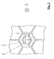
- schematisch die Draufsicht auf das Dämpfungselement gemäß Fig. 1,
- Fig. 3
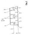
- eine der Fig. 1 entsprechende Darstellung, wobei sich das Dämpfungselement im verformten Zustand befindet,
- Fig. 4
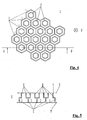
- ein Dämpfungselement, bestehend aus einer Anzahl von Einzelelementen in der Draufsicht,
- Fig. 5
- den Schnitt A-B gemäß Fig. 4,
- Fig. 6a
- ein Dämpfungselement bestehend aus einer Anzahl von Einzelelementen in der Vorderansicht,
- Fig. 6b
- die zu Fig. 6a zugehörige Draufsicht,
- Fig. 6c
- die zu Fig. 6a zugehörige Seitenansicht und
- Fig. 7
- das Dämpfungselement nach Fig. 6a, 6b bzw. 6c in perspektivischer Ansicht.
- Fig. 1
- schematically the side view of a damping element in section,
- Fig. 2
- 1 is a schematic plan view of the damping element according to FIG. 1, FIG.
- Fig. 3
- 1 corresponding representation, wherein the damping element is in the deformed state,
- Fig. 4
- a damping element consisting of a number of individual elements in plan view,
- Fig. 5
- the section AB according to FIG. 4,
- Fig. 6a
- a damping element consisting of a number of individual elements in the front view,
- Fig. 6b
- the plan view associated with FIG. 6a,
- Fig. 6c
- the associated to Fig. 6a side view and
- Fig. 7
- the damping element according to Fig. 6a, 6b and 6c in a perspective view.
In Fig. 1 ist ein Dämpfungselement 1 im Schnitt dargestellt. Das Dämpfungselement 1 ist in einem - nicht dargestellten - Schuh, insbesondere in der Sohle eines Sportschuhs, integriert. Es dient dazu, bei Belastung der Sohle in Belastungsrichtung R Energie aufzunehmen und bei Entlastung der Sohle die im Dämpfungselement 1 gespeicherte Energie wieder abzugeben.In Fig. 1, a damping
Wie in der Zusammenschau mit Fig. 2 ersichtlich ist, weist das Dämpfungselement 1 ein erstes Element 2 und ein zweites Element 4 auf, die sechseckig nach Art eines Wabenmusters ausgebildet sind. Das erste Element 2 weist einen Aufnahmeraum 3 auf, der sich aus dem Rauminhalt des sechseckigen Körpers ergibt. Die Erstreckung des ersten Elements 2 in Belastungsrichtung R ist mit H angegeben (Höhe des ersten Elements 2 im unbelasteten Zustand des Dämpfungselements 1). Axial oberhalb des ersten Elements 2 ist - im unbelasteten Zustand des Dämpfungselements 1 - das zweite Element 4 angeordnet, das sich über eine axiale Höhe h in Belastungsrichtung R erstreckt. Wie insbesondere aus Fig. 2 hervorgeht, sind dabei die Abmessungen - Breite B des ersten Elements 2 und Breite b des zweiten Elements 4 - so gewählt, dass das zweite Element 4 bei Belastung des Dämpfungselements 1 in Belastungsrichtung R in den Aufnahmeraum 3 eintreten kann, der durch das erste Element 2 definiert ist. Das erste Element 2 und das zweite Element 4 arbeiten demzufolge nach Art eines Teleskop-Dämpfers, wobei das erste Element 2 als "Zylinder" fungiert, in das das zweite Element 4 nach Art eines "Kolbens" eintreten kann.As can be seen in conjunction with FIG. 2, the damping
Damit dies unter Erzielung eines Rückstelleffekts bei Druckentlastung des Dämpfungselements 1 erfolgen kann, ist der in Fig. 1 zu sehende obere axiale Endbereich des ersten Elements 2 und der axiale untere Endbereich des zweiten Elements 4 über einen Verbindungsabschnitt 5 miteinander verbunden. Es handelt sich bei dem Verbindungsabschnitt 5 - wie auch beim ersten und zweiten Element 2, 4 - um ein Teil aus elastischem Kunststoffmaterial, so dass bei Aufgabe einer Belastungskraft auf das Dämpfungselement 1 in Belastungsrichtung R eine Verformung stattfindet, wie sie schematisch in Fig. 3 dargestellt ist. Das zweite Element 4 tritt kolbenartig in den Aufnahmeraum 3 des ersten Elements 2 ein.So that this can take place while achieving a restoring effect when pressure is released from the damping
Damit nach Druckentlastung des Dämpfungselements 1 der Ausgangszustand wieder erreicht wird, wie er in Fig. 1 skizziert ist, wird nicht nur der Verbindungsabschnitt 5 elastisch ausgeführt, sondern es werden weiterhin folgende Maßnahmen ergriffen:Thus, after pressure relief of the damping
Das dem zweiten Element 4 abgewandte Ende 6 des ersten Elements 2 ist mit einer ersten Dichtfolie 7 verbunden, insbesondere verschweißt. In gleicher Weise ist das dem ersten Element 2 abgewandte Ende 8 des zweiten Elements 4 mit einer zweiten Dichtfolie 9 versehen. Auch diese Dichtfolie 9 ist mit dem zweiten Element 4 verbunden, vorzugsweise verschweißt. Damit bilden das erste Element 2, das zweite Element 4, der Verbindungsabschnitt 5 und die beiden Dichtfolien 7 und 9 einen gasdicht abgeschlossenen Raum, der optimale Feder- und Dämpfeigenschaften aufweist.The
Einzelne "Kolben-Zylinder-Elemente", bestehend aus den Bauteilen 2, 4, 5, 7 und 9, wie sie in den Figuren 1 bis 3 dargestellt sind, können - wie es den Fig. 4 und Fig. 5 entnommen werden kann - zur Bildung eines Dämpfungselements 1 mit größerer flächiger Erstreckung nebeneinander angeordnet werden. Besonders bevorzugt sind hierzu die Elemente 2 und 4 sechseckig bzw. nach Art eines Wabenmusters ausgebildet.Individual "piston-cylinder elements", consisting of the
Während die als "Zylinder" fungierenden unteren Wabenelemente 2 gemäß Fig. 5 miteinander verbunden sind, stehen die oberen "Kolben" 4 frei nebeneinander und werden lediglich durch die Dichtfolie 9 miteinander verbunden. Die Verbindung zwischen den "Zylindern" 2 und den "Kolben" 4 erfolgt über die Verbindungsabschnitte 5, die - wie es in Fig. 5 erkennbar ist - gewölbt ausgebildet sind. Dadurch wird der Eintritt der "Kolben" 4 in die "Zylinder" 2 bei Einleitung einer Belastungskraft in Belastungsrichtung R begünstigt.While the
Das gesamte in Fig. 4 dargestellte Dämpfungselement 1 kann - entsprechend zugeschnitten - in einen Schuh und dort insbesondere in eine Zwischensohle eingebracht sein.The entire damping
Bei Belastung des Dämpfungselements 1 drücken sich die "Kolben" 4 in die "Zylinder" 2, da die im wesentlichen waagrecht liegenden Verbindungsabschnitte 5 nicht so steif sind, wie die im Wesentlichen senkrecht stehenden Zellenwände der ersten bzw. zweiten Elemente 2, 4.When the damping
Mit steigender Kraft drücken sich die zweiten Elemente 4 mehr und mehr in den axialen Bereich der ersten Elemente 2 ein.As the force increases, the
Somit erhält man eine entsprechend der Belastung des Dämpfungselements 1 entgegenwirkende Kraft, bis die "Kolben" 4 ganz in die "Zylinder" 2 gedrückt sind.Thus, one receives according to the load of the damping
Bei Druckentlastung des Dämpfungselements 1 bildet sich wieder die ursprüngliche Geometrie zurück, wie sie in den Figuren 1 bzw. 5 skizziert ist.Upon pressure relief of the damping
Zur Anordnung der Dichtfolien 7 und 9 sei noch folgendes angemerkt: Im Ausführungsbeispiel gemäß den Figuren 1 bis 5 erstreckt sich die flächige Dichtfolie 7 bzw. 9 über eine Anzahl nebeneinander angeordneter "Kolben-Zylinder-Elemente", d. h. eine Folie 7, 9 deckt eine Anzahl solcher Elemente ab. Es kann aber auch - alternativ hierzu - vorgesehen werden, dass nur einzelne Folienabschnitte zum Einsatz kommen, die jeweils nur ein Ende 6 des ersten Elements 2 und/oder nur ein Ende 9 des zweiten Elements 4 gasdicht verschließen. Diese Folienabschnitte bilden dann also einen "Deckel", der die Endbereiche der Elemente 2, 4 verschließt. Dieser "Deckel" kann an die Enden 6 bzw. 8 der Elemente 2 bzw. 4 angeschweißt sein; es ist aber auch möglich, dass er beispielsweise beim Spritzgießen der Elemente 2 bzw. 4 mit angespritzt, d. h. in situ mit angeformt wird. Bevorzugt ist dabei vorgesehen, dass die Enden 6 der ersten Elemente 2 mit einer großflächigen Folie 7 verschlossen werden (wie in Fig. 1 dargestellt), während die Enden 8 der zweiten Elemente 4 lediglich mit einzelnen Folienabschnitten 9 in Form von "Deckeln" verschlossen sind.For the arrangement of the sealing foils 7 and 9, the following should be noted: In the exemplary embodiment according to FIGS. 1 to 5, the
In den Figuren 6a, 6b, 6c und 7 ist eine alternative Ausgestaltung des Dämpfungselements zu sehen. Hier ist vorgesehen, dass eine Vielzahl erster und zweiter Elemente 2 und 4 nebeneinander angeordnet sind. Dabei sind die ersten und zweiten Elemente 2 bzw. 4 mit Abstand und parallel zueinander positioniert (dargestellt ohne Folien 7 bzw. 9, s. Fig. 1).FIGS. 6a, 6b, 6c and 7 show an alternative embodiment of the damping element. Here it is provided that a plurality of first and
Die Verbindung der einzelnen Einheiten, bestehend aus jeweils einem ersten und einem zweiten Element 2 bzw. 4, erfolgt über die Verbindungsabschnitte 5, die auch das erste und das zweite Element 2, 4 miteinander verbinden. Die Verbindungsabschnitte 5 stellen also nicht nur die Verbindung zwischen erstem und zweitem Element 2, 4 - in axiale Richtung - her, sondern auch die Verbindung der einzelnen Teilelemente zu der Struktur, die in den genannten Figuren dargestellt ist.The connection of the individual units, each consisting of a first and a
Wie vor allem Fig. 6c und auch Fig. 7 entnommen werden kann, ist dabei vorgesehen, dass die ersten bzw. zweiten Elemente 2 und 4 zumindest teilweise im dargestellten unbelasteten Zustand des Dämpfungselements unterschiedliche Höhen H bzw. h (s. Fig. 1) aufweisen.As can be seen in particular from Fig. 6c and also Fig. 7, it is provided that the first and
Durch Anpassung der Geometrie und hier insbesondere dieser Höhen sowie der Breiten der einzelnen Elemente 2 und 4, der Dicke und Ausgestaltung der Verbindungsabschnitte 5 und auch durch entsprechende Wahl des Materials, aus dem diese Teile bestehen, kann die Feder- und Dämpfungscharakteristik des Dämpfungselements 1 beliebig angepasst bzw. gewählt werden.By adapting the geometry and in particular these heights and the widths of the
Die Feder- und Dämpfungscharakteristik des Dämpfungselements 1 - insbesondere die Federkraft über den Federweg - kann damit weitgehend gemäß einem gewünschten Verlauf gewählt werden.The spring and damping characteristic of the damping element 1 - in particular the spring force on the spring travel - can thus be largely selected according to a desired course.
Die jeweilige Funktion, die das einzelne Teil-Dämpfungselement bestehend aus erstem Elemente, zweitem Element und Verbindungsabschnitt erfüllen muss, kann damit beeinflusst werden, d. h. ob es eher ein Stütz- oder ein Dämpfeffekt benötigt wird.The respective function, which must fulfill the individual partial damping element consisting of the first element, the second element and the connecting section, can thus be influenced, ie. H. whether it is more of a support or a damping effect is needed.
Das erfindungsgemäße Dämpfungselement 1 kann auch mit einem konventionellen Dämpfungselement, wie es im Stand der Technik bekannt ist, in einem Schuh, insbesondere Sportschuh, in Kombination verwendet werden. Damit ergeben sich weitere Möglichkeiten, das Feder- und Dämpfungsverhalten eines Schuhs, insbesondere eines Sportschuhs, den jeweiligen Bedürfnissen optimal anpassen zu können.The damping
- 11
- Dämpfungselementdamping element
- 22
- erstes Elementfirst element
- 33
- Aufnahmeraumaccommodation space
- 44
- zweites Elementsecond element
- 55
- Verbindungsabschnittconnecting portion
- 66
- Ende des ersten ElementsEnd of the first element
- 77
- Dichtfoliesealing film
- 88th
- Ende des zweiten ElementsEnd of the second element
- 99
- Dichtfoliesealing film
- RR
- Belastungsrichtungload direction
- HH
- Höhe des ersten ElementsHeight of the first element
- hH
- Höhe des zweiten ElementsHeight of the second element
- BB
- Abmessung des ersten ElementsDimension of the first element
- bb
- Abmessung des zweiten ElementsDimension of the second element
Claims (21)
- Damping element (1) for a shoe, in particular for a sports shoe, consisting of at least one first element (2) which essentially extends over a predetermined height (H) in a loading direction (R) in the unladen state of the damping element (1) and, embodied as a hollow body, defines a receiving space (3) into which a corresponding second element (4), of smaller dimensions in cross-section than the first element (2), can at least partly penetrate, the second element (4) essentially extending over a predetermined height (h) in the loading direction (R) in the unladen state of the damping element (1) and being arranged coaxially with the first element (2), wherein the second element (4) is also embodied as a hollow body, wherein the two associated elements (2, 4) are connected to one another through an elastic connecting portion (5) which only extends between the first element (2) and the second element (4),
characterized in that
the first element (2) and the second element (4) exhibit a corresponding form, namely a polygonal, in particular hexagonal, form in a section perpendicular to the loading direction (R). - Damping element according to claim 1, characterized in that the connecting portion (5) runs flat in a plane perpendicular to the loading direction (R) in the unladen state of the damping element (1).
- Damping element according to claim 1, characterized in that the connecting portion (5) runs in a curve in a plane perpendicular to the loading direction (R) in the unladen state of the damping element (1).
- Damping element according to one of claims 1 to 3, characterized in that the first element (2), the connecting portion (5) and the second element (4) are embodied in one piece.
- Damping element according to one of claims 1 to 4, characterized in that the first element (2) and the second element (4) are manufactured by an injection moulding process.
- Damping element according to claim 4 and 5, characterized in that the first element (2), the connecting portion (5) and the second element (4) are manufactured by a common injection moulding process.
- Damping element according to one of claims 1 to 6, characterized in that the end (6) of the first element (2) remote from the second element (4) is connected to a sealing film (7).
- Damping element according to one of claims 1 to 7, characterized in that the end (8) of the second element (4) remote from the first element (2) is connected to a sealing film (9).
- Damping element according to claim 7 or 8, characterized in that the elements (2, 4) and the sealing films (7, 9) are connected to one another in a gas-tight manner, in particular welded.
- Damping element according to one of claims 7 to 9, characterized in that the first element (2), the second element (4), the connecting portion (5) and the sealing films (7, 9) form a gas-tight sealed flexible chamber.
- Damping element according to one of claims 1 to 10, characterized in that the elements (2, 4) are made of plastic, in particular of thermoplastic material.
- Damping element according to claim 11, characterized in that polyethylene, polypropylene, polybutane, polyamide, polyurethane or a mixture of at least two of these plastics is provided as the plastic.
- Damping element according to claim 11 or 12, characterized in that the plastic is translucent or transparent.
- Damping element according to one of claims 1 to 13, characterized in that a plurality of first and/or second elements (2, 4) are connected to one another.
- Damping element according to claim 14, characterized in that the first elements (2) are connected to one another in their side area.
- Damping element according to one of claims 1 to 13, characterized in that a plurality of first and second elements (2, 4) are arranged next to one another.
- Damping element according to claim 16, characterized in that the connecting portion (5) of at least two adjoining first or second elements (2, 4) is embodied as a common part.
- Damping element according to claim 17, characterized in that the plurality of first and second elements (2, 4) arranged next to one another are connected to one another through the connecting portions (5).
- Damping element according to one of claims 16 to 18, characterized in that the first and second elements (2, 4) are arranged at distance from and parallel with one another.
- Damping element according to one of claims 14 to 19, characterized in that the first and/or second elements (2, 4) exhibit different heights (H, h) at least in part in the unladen state of the damping element (1).
- Damping element according to one of claims 1 to 20, characterized in that the material of the first element (2), the second element (4) and the connecting portion (5), and the geometric dimensions of these parts are selected to determine the damping properties of the damping element (1).
Applications Claiming Priority (3)
| Application Number | Priority Date | Filing Date | Title |
|---|---|---|---|
| DE20206927U | 2002-05-01 | ||
| DE20206927U DE20206927U1 (en) | 2002-05-01 | 2002-05-01 | Damping element for a shoe |
| EP03729837A EP1499209B1 (en) | 2002-05-01 | 2003-04-15 | Damping element for a shoe |
Related Parent Applications (1)
| Application Number | Title | Priority Date | Filing Date |
|---|---|---|---|
| EP03729837A Division EP1499209B1 (en) | 2002-05-01 | 2003-04-15 | Damping element for a shoe |
Publications (2)
| Publication Number | Publication Date |
|---|---|
| EP1563751A1 EP1563751A1 (en) | 2005-08-17 |
| EP1563751B1 true EP1563751B1 (en) | 2006-09-06 |
Family
ID=27816299
Family Applications (2)
| Application Number | Title | Priority Date | Filing Date |
|---|---|---|---|
| EP05010930A Expired - Lifetime EP1563751B1 (en) | 2002-05-01 | 2003-04-15 | Damping element for a shoe |
| EP03729837A Expired - Lifetime EP1499209B1 (en) | 2002-05-01 | 2003-04-15 | Damping element for a shoe |
Family Applications After (1)
| Application Number | Title | Priority Date | Filing Date |
|---|---|---|---|
| EP03729837A Expired - Lifetime EP1499209B1 (en) | 2002-05-01 | 2003-04-15 | Damping element for a shoe |
Country Status (18)
| Country | Link |
|---|---|
| US (1) | US7153560B2 (en) |
| EP (2) | EP1563751B1 (en) |
| JP (1) | JP2005532845A (en) |
| KR (1) | KR100611426B1 (en) |
| CN (1) | CN100438792C (en) |
| AT (2) | ATE308256T1 (en) |
| AU (1) | AU2003240394B2 (en) |
| BR (1) | BR0308463B1 (en) |
| CA (1) | CA2477760C (en) |
| DE (4) | DE20206927U1 (en) |
| ES (2) | ES2248751T3 (en) |
| IL (2) | IL163747A0 (en) |
| MX (1) | MXPA04010799A (en) |
| NO (1) | NO325469B1 (en) |
| PL (1) | PL205489B1 (en) |
| RU (1) | RU2279235C2 (en) |
| WO (1) | WO2003092423A1 (en) |
| ZA (1) | ZA200406926B (en) |
Families Citing this family (68)
| Publication number | Priority date | Publication date | Assignee | Title |
|---|---|---|---|---|
| US7089690B2 (en) * | 2002-05-29 | 2006-08-15 | Nike, Inc. | Material having compressible projections and footwear incorporating the material |
| DE202005001006U1 (en) | 2005-01-22 | 2006-06-01 | Puma Aktiengesellschaft Rudolf Dassler Sport | Shoe, in particular sports shoe |
| DE202005001005U1 (en) | 2005-01-22 | 2006-06-08 | Puma Aktiengesellschaft Rudolf Dassler Sport | Shoe, in particular sports shoe |
| US8661564B2 (en) * | 2005-02-15 | 2014-03-04 | Pinwrest Development Group, LLC. | Protective articles having a plurality of core members |
| US7513066B2 (en) | 2005-04-14 | 2009-04-07 | Nike, Inc. | Fluid-filled bladder for footwear and other applications |
| US7399517B2 (en) * | 2005-04-19 | 2008-07-15 | I Shing Trade Co., Ltd. | Cushion pad for shoes |
| DE202005012062U1 (en) * | 2005-08-01 | 2006-12-14 | Puma Aktiengesellschaft Rudolf Dassler Sport | Shoe, in particular sports shoe |
| DE202005017306U1 (en) | 2005-11-05 | 2007-03-15 | Puma Aktiengesellschaft Rudolf Dassler Sport | Shoe, in particular sports shoe |
| DE102009049093A1 (en) * | 2009-10-01 | 2011-04-07 | Kaco Gmbh + Co. Kg | Mechanical seal |
| US8296971B2 (en) * | 2010-01-13 | 2012-10-30 | Majak Walter H | Device for relieving pressure from a selected area of an animal's skin and methods of fabricating and applying the same |
| CN102349727B (en) * | 2011-10-12 | 2013-06-05 | 茂泰(福建)鞋材有限公司 | Damping sole and shoe comprising same |
| US9271543B2 (en) | 2012-01-11 | 2016-03-01 | Nike, Inc. | Article of footwear with support assembly having sealed chamber |
| USD708830S1 (en) * | 2013-11-12 | 2014-07-15 | Nike, Inc. | Shoe outsole |
| USD712126S1 (en) * | 2013-11-12 | 2014-09-02 | Nike, Inc. | Shoe outsole |
| USD704424S1 (en) * | 2013-11-12 | 2014-05-13 | Nike, Inc. | Shoe outsole |
| USD707934S1 (en) * | 2013-11-30 | 2014-07-01 | Nike, Inc. | Shoe outsole |
| USD709276S1 (en) * | 2013-11-30 | 2014-07-22 | Nike, Inc. | Shoe outsole |
| USD756094S1 (en) | 2014-02-07 | 2016-05-17 | New Balance Athletics, Inc. | Shoe sole |
| USD744735S1 (en) | 2014-02-07 | 2015-12-08 | New Balance Athletic Shoe, Inc. | Shoe sole |
| USD752325S1 (en) | 2014-02-07 | 2016-03-29 | New Balance Athletics, Inc. | Shoe sole |
| USD744731S1 (en) | 2014-02-07 | 2015-12-08 | New Balance Athletic Shoe, Inc. | Shoe sole |
| USD758708S1 (en) | 2014-02-07 | 2016-06-14 | New Balance Athletics, Inc. | Shoe sole |
| USD734602S1 (en) * | 2014-02-10 | 2015-07-21 | Genesco Licensed Brands | Footwear grip |
| CN106170219B (en) | 2014-02-12 | 2020-02-11 | 新平衡运动公司 | Sole for footwear, and systems and methods for designing and manufacturing same |
| USD713629S1 (en) * | 2014-02-28 | 2014-09-23 | Nike, Inc. | Shoe outsole |
| USD708831S1 (en) * | 2014-02-28 | 2014-07-15 | Nike, Inc. | Shoe outsole |
| USD723254S1 (en) * | 2014-05-30 | 2015-03-03 | Nike, Inc. | Shoe outsole |
| USD722753S1 (en) * | 2014-05-30 | 2015-02-24 | Nike, Inc. | Shoe outsole |
| USD724301S1 (en) * | 2014-05-31 | 2015-03-17 | Nike, Inc. | Shoe outsole |
| USD721226S1 (en) * | 2014-05-31 | 2015-01-20 | Nike, Inc. | Shoe outsole |
| USD724299S1 (en) * | 2014-05-31 | 2015-03-17 | Nike, Inc. | Shoe outsole |
| USD755491S1 (en) * | 2014-09-05 | 2016-05-10 | Wolverine World Wide, Inc. | Footwear sole |
| USD756095S1 (en) * | 2014-09-05 | 2016-05-17 | Wolverine World Wide, Inc. | Footwear sole component |
| USD734932S1 (en) * | 2014-11-26 | 2015-07-28 | Nike, Inc. | Shoe outsole |
| US9901135B2 (en) | 2014-12-09 | 2018-02-27 | Nike, Inc. | Footwear with flexible auxetic ground engaging members |
| US9681703B2 (en) | 2014-12-09 | 2017-06-20 | Nike, Inc. | Footwear with flexible auxetic sole structure |
| US9775408B2 (en) * | 2014-12-09 | 2017-10-03 | Nike, Inc. | Footwear with auxetic ground engaging members |
| USD744216S1 (en) * | 2015-02-12 | 2015-12-01 | Nike, Inc. | Shoe outsole |
| USD743680S1 (en) * | 2015-02-12 | 2015-11-24 | Nike, Inc. | Shoe outsole |
| USD764778S1 (en) * | 2015-02-18 | 2016-08-30 | Nike, Inc. | Shoe outsole |
| USD764779S1 (en) * | 2015-02-18 | 2016-08-30 | Nike, Inc. | Shoe outsole |
| US9861158B2 (en) * | 2015-03-10 | 2018-01-09 | Nike, Inc. | Auxetic structures and footwear with soles having auxetic structures |
| USD746565S1 (en) * | 2015-03-16 | 2016-01-05 | Nike, Inc. | Shoe outsole |
| USD744217S1 (en) * | 2015-03-17 | 2015-12-01 | Nike, Inc. | Shoe outsole |
| USD765372S1 (en) * | 2015-04-10 | 2016-09-06 | Nike, Inc. | Shoe outsole |
| USD746566S1 (en) * | 2015-05-01 | 2016-01-05 | Nike, Inc. | Shoe outsole |
| USD770154S1 (en) * | 2015-05-08 | 2016-11-01 | Nike, Inc. | Shoe outsole |
| USD776905S1 (en) * | 2015-05-17 | 2017-01-24 | Nike, Inc. | Shoe outsole |
| USD746567S1 (en) * | 2015-05-19 | 2016-01-05 | Nike, Inc. | Shoe outsole |
| USD779180S1 (en) * | 2015-08-18 | 2017-02-21 | Nike, Inc. | Shoe outsole |
| JP6554557B2 (en) | 2015-09-22 | 2019-07-31 | プーマ エス イーPuma Se | Shoes, especially sports shoes |
| USD783969S1 (en) * | 2015-10-27 | 2017-04-18 | Nike, Inc. | Shoe outsole |
| JP6995826B2 (en) * | 2016-03-16 | 2022-01-17 | アルキスター エスアールエル | Shoe sole |
| EP3454690B1 (en) * | 2016-05-11 | 2019-11-06 | Puma Se | Shoe, in particular sports shoe |
| US10638812B2 (en) * | 2017-05-24 | 2020-05-05 | Nike, Inc. | Flexible sole for article of footwear |
| USD815407S1 (en) * | 2017-08-12 | 2018-04-17 | Nike, Inc. | Shoe outsole |
| USD816964S1 (en) * | 2017-08-15 | 2018-05-08 | Nike, Inc. | Shoe outsole |
| US10912388B2 (en) * | 2017-12-15 | 2021-02-09 | Illinois Tool Works Inc. | Cushioned load bearing surface and method for making same |
| US10548370B2 (en) | 2018-02-28 | 2020-02-04 | Rockport Ip Holdings, Llc | Shoe sole construction |
| CN112135727B (en) | 2018-05-08 | 2023-02-03 | 彪马欧洲股份公司 | Method for producing soles for shoes, especially sports shoes |
| WO2019214814A1 (en) | 2018-05-08 | 2019-11-14 | Puma SE | Sole of a shoe, particularly an athletic shoe |
| CA3110792A1 (en) * | 2018-08-31 | 2020-03-05 | Materialise N.V. | Cushioning structures |
| WO2020056097A1 (en) * | 2018-09-12 | 2020-03-19 | Worcester Polytechnic Institute | Downwards absorbing and upwards accommodating footwear heel |
| US11071348B2 (en) * | 2018-09-20 | 2021-07-27 | Nike, Inc. | Footwear sole structure |
| CN210611192U (en) * | 2019-04-03 | 2020-05-26 | 霍尼韦尔国际公司 | Footwear outsole with resistance elements |
| US12478134B2 (en) | 2019-10-21 | 2025-11-25 | Puma SE | Article of footwear |
| EP3824753B1 (en) * | 2019-11-20 | 2024-10-16 | Caprice Schuhproduktion GmbH & Co. KG | Cushioning shoe sole assembly |
| US12109775B2 (en) | 2021-12-22 | 2024-10-08 | Puma SE | Method for producing a sole of a shoe |
Family Cites Families (16)
| Publication number | Priority date | Publication date | Assignee | Title |
|---|---|---|---|---|
| US3608215A (en) * | 1969-06-14 | 1971-09-28 | Tatsuo Fukuoka | Footwear |
| DE3338556A1 (en) | 1983-10-24 | 1985-05-15 | Dassler Puma Sportschuh | SPORTSHOE, ESPECIALLY FOR RUNNING DISCIPLINES |
| DE3430845A1 (en) * | 1983-12-09 | 1985-07-04 | adidas Sportschuhfabriken Adi Dassler Stiftung & Co KG, 8522 Herzogenaurach | OUTSOLE FOR SHOES, ESPECIALLY SPORTSHOES WITH ADJUSTABLE HEEL DAMPING |
| US4521979A (en) * | 1984-03-01 | 1985-06-11 | Blaser Anton J | Shock absorbing shoe sole |
| DE8901236U1 (en) * | 1989-02-03 | 1990-06-07 | Puma Ag Rudolf Dassler Sport, 91074 Herzogenaurach | Shoe, especially sports shoe or rehabilitation shoe |
| DE8904649U1 (en) * | 1989-04-13 | 1990-08-09 | PUMA AG Rudolf Dassler Sport, 8522 Herzogenaurach | Shoe, especially sports shoe |
| GB8909021D0 (en) * | 1989-04-20 | 1989-06-07 | Trisport Ltd | Footwear |
| DE9106226U1 (en) * | 1990-05-31 | 1991-09-26 | Puma Ag Rudolf Dassler Sport, 91074 Herzogenaurach | Shoe, especially sports shoe or rehabilitation shoe |
| DE9106223U1 (en) * | 1990-05-31 | 1991-09-26 | Puma Ag Rudolf Dassler Sport, 91074 Herzogenaurach | Shoe, especially sports shoe or rehabilitation shoe |
| DE9106224U1 (en) * | 1990-05-31 | 1991-09-26 | Puma Ag Rudolf Dassler Sport, 91074 Herzogenaurach | Shoe, especially sports shoe or rehabilitation shoe |
| RU2050807C1 (en) * | 1993-06-07 | 1995-12-27 | Российский заочный институт текстильной и легкой промышленности | Shock-absorbing heel |
| US5915819A (en) * | 1996-11-26 | 1999-06-29 | Gooding; Elwyn | Adaptive, energy absorbing structure |
| US5815950A (en) * | 1997-09-11 | 1998-10-06 | Wang; Sui-Mu | Air-cushioning sole insert lined with iridescent film |
| WO1999035928A1 (en) * | 1998-01-20 | 1999-07-22 | Snow A Ray | Shoe with force responsive sole |
| US6571490B2 (en) * | 2000-03-16 | 2003-06-03 | Nike, Inc. | Bladder with multi-stage regionalized cushioning |
| CN2430040Y (en) * | 2000-06-20 | 2001-05-16 | 蔡双珠 | Improved structure of shoe pad |
-
2002
- 2002-05-01 DE DE20206927U patent/DE20206927U1/en not_active Expired - Lifetime
-
2003
- 2003-04-15 AT AT03729837T patent/ATE308256T1/en not_active IP Right Cessation
- 2003-04-15 AT AT05010930T patent/ATE338486T1/en not_active IP Right Cessation
- 2003-04-15 CN CNB038083639A patent/CN100438792C/en not_active Expired - Lifetime
- 2003-04-15 PL PL371619A patent/PL205489B1/en unknown
- 2003-04-15 ES ES03729837T patent/ES2248751T3/en not_active Expired - Lifetime
- 2003-04-15 DE DE10392004T patent/DE10392004D2/en not_active Expired - Fee Related
- 2003-04-15 EP EP05010930A patent/EP1563751B1/en not_active Expired - Lifetime
- 2003-04-15 KR KR1020047017537A patent/KR100611426B1/en not_active Expired - Lifetime
- 2003-04-15 IL IL16374703A patent/IL163747A0/en unknown
- 2003-04-15 ES ES05010930T patent/ES2273297T3/en not_active Expired - Lifetime
- 2003-04-15 US US10/513,087 patent/US7153560B2/en not_active Expired - Lifetime
- 2003-04-15 DE DE50301557T patent/DE50301557D1/en not_active Expired - Lifetime
- 2003-04-15 CA CA002477760A patent/CA2477760C/en not_active Expired - Lifetime
- 2003-04-15 JP JP2004500617A patent/JP2005532845A/en active Pending
- 2003-04-15 DE DE50304985T patent/DE50304985D1/en not_active Expired - Lifetime
- 2003-04-15 AU AU2003240394A patent/AU2003240394B2/en not_active Ceased
- 2003-04-15 EP EP03729837A patent/EP1499209B1/en not_active Expired - Lifetime
- 2003-04-15 WO PCT/DE2003/001272 patent/WO2003092423A1/en not_active Ceased
- 2003-04-15 BR BRPI0308463-9B1A patent/BR0308463B1/en active IP Right Grant
- 2003-04-15 RU RU2004135077/12A patent/RU2279235C2/en active
- 2003-04-15 MX MXPA04010799A patent/MXPA04010799A/en active IP Right Grant
-
2004
- 2004-08-26 IL IL163747A patent/IL163747A/en not_active IP Right Cessation
- 2004-08-31 ZA ZA200406926A patent/ZA200406926B/en unknown
- 2004-11-30 NO NO20045254A patent/NO325469B1/en unknown
Also Published As
Similar Documents
| Publication | Publication Date | Title |
|---|---|---|
| EP1563751B1 (en) | Damping element for a shoe | |
| EP1945054B1 (en) | Shoe, in particular sports shoe | |
| DE3508308C2 (en) | Sports shoe | |
| DE19947245B4 (en) | Device for absorbing impact energy | |
| EP1945053A1 (en) | Shoe, particularly an athletic shoe | |
| DE3338557A1 (en) | SPORTSHOE WITH A SHOCK ABSORBING OUTSOLE AND METHOD FOR PRODUCING SUCH A SPORTSHOE | |
| DE10297242T5 (en) | Carrier for a bumper of a vehicle with a cross member and two bumpers | |
| DE202009016759U1 (en) | energy absorber | |
| EP1286732B1 (en) | Stiffening and/or damping element for a sliding device, especially for a ski or snowboard | |
| DE102016000599A1 (en) | crash box | |
| DE2431217A1 (en) | SEAL ARRANGEMENT | |
| EP1843676B1 (en) | Shoe, in particular a sports shoe | |
| EP1843675B1 (en) | Shoe, in particular a sports shoe | |
| DE19916619C2 (en) | Composite component | |
| EP0875164B1 (en) | Energy-storing shoe-bottom construction for security shoes | |
| EP1818240A1 (en) | Pressure yoke for a steering gear | |
| DE69506976T2 (en) | Liner for ski boot | |
| DE29906831U1 (en) | Injection mold for the encapsulation of plastic around a filter material and filter for filtering fluids | |
| DE602004011657T2 (en) | Lateral reinforcement for picking up bumping quantities for vehicle doors | |
| EP0644980B1 (en) | Corner area of a sealing frame for a tunnel tubbing | |
| DE102006002853B4 (en) | Pressure force sensor for detecting an external impact load on a motor vehicle | |
| DE3832743A1 (en) | Outsole with damping midsole | |
| WO2007014712A1 (en) | Shoe, particularly sports shoe | |
| DE202024102468U1 (en) | Crash absorption device | |
| DE2954437C2 (en) |
Legal Events
| Date | Code | Title | Description |
|---|---|---|---|
| PUAI | Public reference made under article 153(3) epc to a published international application that has entered the european phase |
Free format text: ORIGINAL CODE: 0009012 |
|
| AC | Divisional application: reference to earlier application |
Ref document number: 1499209 Country of ref document: EP Kind code of ref document: P |
|
| AK | Designated contracting states |
Kind code of ref document: A1 Designated state(s): AT BE BG CH CY CZ DE DK EE ES FI FR GB GR HU IE IT LI LU MC NL PT RO SE SI SK TR |
|
| 17P | Request for examination filed |
Effective date: 20050926 |
|
| GRAP | Despatch of communication of intention to grant a patent |
Free format text: ORIGINAL CODE: EPIDOSNIGR1 |
|
| AKX | Designation fees paid |
Designated state(s): AT BE BG CH CY CZ DE DK EE ES FI FR GB GR HU IE IT LI LU MC NL PT RO SE SI SK TR |
|
| GRAS | Grant fee paid |
Free format text: ORIGINAL CODE: EPIDOSNIGR3 |
|
| GRAA | (expected) grant |
Free format text: ORIGINAL CODE: 0009210 |
|
| AC | Divisional application: reference to earlier application |
Ref document number: 1499209 Country of ref document: EP Kind code of ref document: P |
|
| AK | Designated contracting states |
Kind code of ref document: B1 Designated state(s): AT BE BG CH CY CZ DE DK EE ES FI FR GB GR HU IE IT LI LU MC NL PT RO SE SI SK TR |
|
| PG25 | Lapsed in a contracting state [announced via postgrant information from national office to epo] |
Ref country code: NL Free format text: LAPSE BECAUSE OF FAILURE TO SUBMIT A TRANSLATION OF THE DESCRIPTION OR TO PAY THE FEE WITHIN THE PRESCRIBED TIME-LIMIT Effective date: 20060906 Ref country code: IT Free format text: LAPSE BECAUSE OF FAILURE TO SUBMIT A TRANSLATION OF THE DESCRIPTION OR TO PAY THE FEE WITHIN THE PRESCRIBED TIME-LIMIT;WARNING: LAPSES OF ITALIAN PATENTS WITH EFFECTIVE DATE BEFORE 2007 MAY HAVE OCCURRED AT ANY TIME BEFORE 2007. THE CORRECT EFFECTIVE DATE MAY BE DIFFERENT FROM THE ONE RECORDED. Effective date: 20060906 Ref country code: IE Free format text: LAPSE BECAUSE OF FAILURE TO SUBMIT A TRANSLATION OF THE DESCRIPTION OR TO PAY THE FEE WITHIN THE PRESCRIBED TIME-LIMIT Effective date: 20060906 Ref country code: SK Free format text: LAPSE BECAUSE OF FAILURE TO SUBMIT A TRANSLATION OF THE DESCRIPTION OR TO PAY THE FEE WITHIN THE PRESCRIBED TIME-LIMIT Effective date: 20060906 Ref country code: SI Free format text: LAPSE BECAUSE OF FAILURE TO SUBMIT A TRANSLATION OF THE DESCRIPTION OR TO PAY THE FEE WITHIN THE PRESCRIBED TIME-LIMIT Effective date: 20060906 Ref country code: FI Free format text: LAPSE BECAUSE OF FAILURE TO SUBMIT A TRANSLATION OF THE DESCRIPTION OR TO PAY THE FEE WITHIN THE PRESCRIBED TIME-LIMIT Effective date: 20060906 Ref country code: RO Free format text: LAPSE BECAUSE OF FAILURE TO SUBMIT A TRANSLATION OF THE DESCRIPTION OR TO PAY THE FEE WITHIN THE PRESCRIBED TIME-LIMIT Effective date: 20060906 Ref country code: CZ Free format text: LAPSE BECAUSE OF FAILURE TO SUBMIT A TRANSLATION OF THE DESCRIPTION OR TO PAY THE FEE WITHIN THE PRESCRIBED TIME-LIMIT Effective date: 20060906 |
|
| REG | Reference to a national code |
Ref country code: GB Ref legal event code: FG4D Free format text: NOT ENGLISH |
|
| REG | Reference to a national code |
Ref country code: CH Ref legal event code: EP |
|
| REG | Reference to a national code |
Ref country code: IE Ref legal event code: FG4D Free format text: LANGUAGE OF EP DOCUMENT: GERMAN |
|
| REF | Corresponds to: |
Ref document number: 50304985 Country of ref document: DE Date of ref document: 20061019 Kind code of ref document: P |
|
| GBT | Gb: translation of ep patent filed (gb section 77(6)(a)/1977) |
Effective date: 20061101 |
|
| PG25 | Lapsed in a contracting state [announced via postgrant information from national office to epo] |
Ref country code: DK Free format text: LAPSE BECAUSE OF FAILURE TO SUBMIT A TRANSLATION OF THE DESCRIPTION OR TO PAY THE FEE WITHIN THE PRESCRIBED TIME-LIMIT Effective date: 20061206 Ref country code: SE Free format text: LAPSE BECAUSE OF FAILURE TO SUBMIT A TRANSLATION OF THE DESCRIPTION OR TO PAY THE FEE WITHIN THE PRESCRIBED TIME-LIMIT Effective date: 20061206 Ref country code: BG Free format text: LAPSE BECAUSE OF FAILURE TO SUBMIT A TRANSLATION OF THE DESCRIPTION OR TO PAY THE FEE WITHIN THE PRESCRIBED TIME-LIMIT Effective date: 20061206 |
|
| PG25 | Lapsed in a contracting state [announced via postgrant information from national office to epo] |
Ref country code: PT Free format text: LAPSE BECAUSE OF FAILURE TO SUBMIT A TRANSLATION OF THE DESCRIPTION OR TO PAY THE FEE WITHIN THE PRESCRIBED TIME-LIMIT Effective date: 20070219 |
|
| NLV1 | Nl: lapsed or annulled due to failure to fulfill the requirements of art. 29p and 29m of the patents act | ||
| ET | Fr: translation filed | ||
| REG | Reference to a national code |
Ref country code: IE Ref legal event code: FD4D |
|
| REG | Reference to a national code |
Ref country code: ES Ref legal event code: FG2A Ref document number: 2273297 Country of ref document: ES Kind code of ref document: T3 |
|
| PLBE | No opposition filed within time limit |
Free format text: ORIGINAL CODE: 0009261 |
|
| STAA | Information on the status of an ep patent application or granted ep patent |
Free format text: STATUS: NO OPPOSITION FILED WITHIN TIME LIMIT |
|
| 26N | No opposition filed |
Effective date: 20070607 |
|
| REG | Reference to a national code |
Ref country code: CH Ref legal event code: PL |
|
| BERE | Be: lapsed |
Owner name: PUMA A.G. RUDOLF DASSLER SPORT Effective date: 20070430 |
|
| PG25 | Lapsed in a contracting state [announced via postgrant information from national office to epo] |
Ref country code: LI Free format text: LAPSE BECAUSE OF NON-PAYMENT OF DUE FEES Effective date: 20070430 Ref country code: CH Free format text: LAPSE BECAUSE OF NON-PAYMENT OF DUE FEES Effective date: 20070430 |
|
| PG25 | Lapsed in a contracting state [announced via postgrant information from national office to epo] |
Ref country code: BE Free format text: LAPSE BECAUSE OF NON-PAYMENT OF DUE FEES Effective date: 20070430 |
|
| PG25 | Lapsed in a contracting state [announced via postgrant information from national office to epo] |
Ref country code: GR Free format text: LAPSE BECAUSE OF FAILURE TO SUBMIT A TRANSLATION OF THE DESCRIPTION OR TO PAY THE FEE WITHIN THE PRESCRIBED TIME-LIMIT Effective date: 20061207 |
|
| PG25 | Lapsed in a contracting state [announced via postgrant information from national office to epo] |
Ref country code: EE Free format text: LAPSE BECAUSE OF FAILURE TO SUBMIT A TRANSLATION OF THE DESCRIPTION OR TO PAY THE FEE WITHIN THE PRESCRIBED TIME-LIMIT Effective date: 20060906 |
|
| PG25 | Lapsed in a contracting state [announced via postgrant information from national office to epo] |
Ref country code: AT Free format text: LAPSE BECAUSE OF NON-PAYMENT OF DUE FEES Effective date: 20070415 |
|
| PG25 | Lapsed in a contracting state [announced via postgrant information from national office to epo] |
Ref country code: MC Free format text: LAPSE BECAUSE OF NON-PAYMENT OF DUE FEES Effective date: 20070430 |
|
| PG25 | Lapsed in a contracting state [announced via postgrant information from national office to epo] |
Ref country code: LU Free format text: LAPSE BECAUSE OF NON-PAYMENT OF DUE FEES Effective date: 20070415 Ref country code: CY Free format text: LAPSE BECAUSE OF FAILURE TO SUBMIT A TRANSLATION OF THE DESCRIPTION OR TO PAY THE FEE WITHIN THE PRESCRIBED TIME-LIMIT Effective date: 20060906 |
|
| PG25 | Lapsed in a contracting state [announced via postgrant information from national office to epo] |
Ref country code: HU Free format text: LAPSE BECAUSE OF FAILURE TO SUBMIT A TRANSLATION OF THE DESCRIPTION OR TO PAY THE FEE WITHIN THE PRESCRIBED TIME-LIMIT Effective date: 20070307 Ref country code: TR Free format text: LAPSE BECAUSE OF FAILURE TO SUBMIT A TRANSLATION OF THE DESCRIPTION OR TO PAY THE FEE WITHIN THE PRESCRIBED TIME-LIMIT Effective date: 20060906 |
|
| REG | Reference to a national code |
Ref country code: DE Ref legal event code: R081 Ref document number: 50304985 Country of ref document: DE Owner name: PUMA SE, DE Free format text: FORMER OWNER: PUMA AG RUDOLF DASSLER SPORT, 91074 HERZOGENAURACH, DE Effective date: 20130912 Ref country code: DE Ref legal event code: R082 Ref document number: 50304985 Country of ref document: DE Representative=s name: GOSDIN, MICHAEL, DIPL.-ING.UNIV. DR.-ING., DE Effective date: 20130912 |
|
| REG | Reference to a national code |
Ref country code: FR Ref legal event code: PLFP Year of fee payment: 14 |
|
| REG | Reference to a national code |
Ref country code: FR Ref legal event code: PLFP Year of fee payment: 15 |
|
| REG | Reference to a national code |
Ref country code: FR Ref legal event code: PLFP Year of fee payment: 16 |
|
| PGFP | Annual fee paid to national office [announced via postgrant information from national office to epo] |
Ref country code: IT Payment date: 20220429 Year of fee payment: 20 Ref country code: GB Payment date: 20220425 Year of fee payment: 20 Ref country code: FR Payment date: 20220420 Year of fee payment: 20 Ref country code: ES Payment date: 20220518 Year of fee payment: 20 Ref country code: DE Payment date: 20220430 Year of fee payment: 20 |
|
| REG | Reference to a national code |
Ref country code: DE Ref legal event code: R071 Ref document number: 50304985 Country of ref document: DE |
|
| REG | Reference to a national code |
Ref country code: ES Ref legal event code: FD2A Effective date: 20230428 |
|
| REG | Reference to a national code |
Ref country code: GB Ref legal event code: PE20 Expiry date: 20230414 |
|
| PG25 | Lapsed in a contracting state [announced via postgrant information from national office to epo] |
Ref country code: ES Free format text: LAPSE BECAUSE OF EXPIRATION OF PROTECTION Effective date: 20230416 |
|
| PG25 | Lapsed in a contracting state [announced via postgrant information from national office to epo] |
Ref country code: GB Free format text: LAPSE BECAUSE OF EXPIRATION OF PROTECTION Effective date: 20230414 |