EP1562400A2 - Replaceable protective membrane of listening device of hearing-aids - Google Patents
Replaceable protective membrane of listening device of hearing-aids Download PDFInfo
- Publication number
- EP1562400A2 EP1562400A2 EP05010122A EP05010122A EP1562400A2 EP 1562400 A2 EP1562400 A2 EP 1562400A2 EP 05010122 A EP05010122 A EP 05010122A EP 05010122 A EP05010122 A EP 05010122A EP 1562400 A2 EP1562400 A2 EP 1562400A2
- Authority
- EP
- European Patent Office
- Prior art keywords
- membrane
- hearing aid
- carrier
- protective element
- rubber
- Prior art date
- Legal status (The legal status is an assumption and is not a legal conclusion. Google has not performed a legal analysis and makes no representation as to the accuracy of the status listed.)
- Granted
Links
Images


Classifications
-
- H—ELECTRICITY
- H04—ELECTRIC COMMUNICATION TECHNIQUE
- H04R—LOUDSPEAKERS, MICROPHONES, GRAMOPHONE PICK-UPS OR LIKE ACOUSTIC ELECTROMECHANICAL TRANSDUCERS; DEAF-AID SETS; PUBLIC ADDRESS SYSTEMS
- H04R25/00—Deaf-aid sets, i.e. electro-acoustic or electro-mechanical hearing aids; Electric tinnitus maskers providing an auditory perception
- H04R25/65—Housing parts, e.g. shells, tips or moulds, or their manufacture
- H04R25/652—Ear tips; Ear moulds
- H04R25/654—Ear wax retarders
-
- H—ELECTRICITY
- H04—ELECTRIC COMMUNICATION TECHNIQUE
- H04R—LOUDSPEAKERS, MICROPHONES, GRAMOPHONE PICK-UPS OR LIKE ACOUSTIC ELECTROMECHANICAL TRANSDUCERS; DEAF-AID SETS; PUBLIC ADDRESS SYSTEMS
- H04R2460/00—Details of hearing devices, i.e. of ear- or headphones covered by H04R1/10 or H04R5/033 but not provided for in any of their subgroups, or of hearing aids covered by H04R25/00 but not provided for in any of its subgroups
- H04R2460/17—Hearing device specific tools used for storing or handling hearing devices or parts thereof, e.g. placement in the ear, replacement of cerumen barriers, repair, cleaning hearing devices
Definitions
- DE 101 04 129 A1 describes a hearing aid with a Filter unit, which is a membrane or sieve-like Contains filter element. To those for sound transmission To increase effective cross-sectional area, is the Filter element inclined executed. A similar arrangement is also described in DE 102 14 189 B4. Here is a relatively large membrane parallel to the ear canal axis arranged and sonicated with a handset. The radiated Sound is then transmitted through a small slit at the Face of the hearing aid shell to the eardrum out radiated.
- EP 0 548 580 A1 describes a handset for hearing aids, which with an outer membrane against cerumen and Moisture is protected. Again, the membrane is not interchangeable but an integral part of the handset.
Abstract
Description
Die vorliegende Erfindung betrifft eine Vorrichtung als
Hörhilfe zum Tragen im Ohr bzw. im oder am Gehörgang gemäss
dem Oberbegriff nach Anspruch 1, ein Verfahren zum
Herstellen eines Schutzelementes für eine Vorrichtung, ein
Montagewerkzeug für die Montage und das Wiederentfernen des
Schutzelementes an einem bzw. von einem Hörgerät sowie ein
Verfahren zur Montage eines Schutzelementes.The present invention relates to a device as
Hearing aid for wearing in the ear or in or on the ear canal according to
the preamble of
Insbesondere bei Im-Ohr Hörhilfen bzw. Hörgeräten besteht die Problematik, dass beim akustischen Ausgang des Hörgerätes gegen das Innenohr hin Verschmutzung, insbesondere durch Cerumen, auftreten kann.Especially with in-ear hearing aids or hearing aids the problem that the acoustic output of Hearing aid against the inner ear pollution, especially by cerumen, may occur.
Aus dem Stand der Technik sind eine Reihe von Massnahmen bekannt, um die Cerumenverschmutzung eines Im-Ohr Hörgerätes zu verhindern bzw. mindestens stark zu reduzieren. Vorgeschlagen wird in der Regel die Verwendung einer Membran als Hörerschutz bei Im-Ohr Hörgeräten. Derartige Membranen sind in einer Vielzahl von früheren Publikationen beschrieben.From the prior art are a number of measures known to the cerumen contamination of an in-ear Hearing aid to prevent or at least strongly to reduce. As a rule, the use is suggested a membrane as a hearing protection in in-ear hearing aids. Such membranes are in a variety of previous ones Publications described.
In US 4,987,597 ist der Einsatz einer mikroporösen Membran beschrieben welche auswechselbar auf Schallaustrittsöffnungen von z.B. Hörgeräten aufgesetzt werden kann.In US 4,987,597 is the use of a microporous membrane which are interchangeable with sound outlet openings from e.g. Hearing aids can be placed.
Im US-Patent 6,164,409 wird eine steife, nicht schalldurchlässige (rigid, non-sound permeable) Membran beschrieben, welche die Schallaustrittsöffnung eines Im-Ohr Hörgerätes hermetisch abdichtet. Die Membran wird vom Hörer in Schwingung versetzt und erzeugt so Schallwellen, die in Frequenz und Amplitude ähnlich sind.In US Pat. No. 6,164,409, a stiff, not sound-permeable (rigid, non-sound permeable) membrane described which the sound outlet of an in-ear Hearing device hermetically seals. The membrane is picked up by the listener vibrated and thus generates sound waves in Frequency and amplitude are similar.
In der DE 19 640 796 A1 wird ein Hörgerät vorgestellt, bei dem der Hörer durch eine Membran vom Trommelfell abgeschlossen ist. Es wird eine dünne Titanmembran vorgeschlagen, die mittels einer Kappe auf den Schallaustrittsstutzen des Hörgerätes aufsetzbar ist.In DE 19 640 796 A1 a hearing aid is presented at that of the listener through a membrane of the eardrum is completed. It becomes a thin titanium membrane proposed that by means of a cap on the Sound outlet of the hearing aid can be placed.
Ein ähnliches System wird in EP 0 835 042 A2 vorgestellt. Hier ist die dünne Titanmembran auch durch entsprechende Oberflächenprägung und eine konkave bzw. konvexe Formgebung als akustischer Filter oder akustische Linse ausgestaltet.A similar system is presented in EP 0 835 042 A2. Here is the thin titanium membrane also by appropriate Surface embossing and a concave or convex shape designed as an acoustic filter or acoustic lens.
Auch im der Patentschrift US 4,953,215 ist eine Membran erwähnt aus einem nicht-porösen Material, welche mindestens eine kleine Bohrung als Schallaustrittsöffnung enthält, wobei diese Öffnung mindestens einen Faktor 10 grösser sein muss als die Membrandicke, um die akustische Transparenz zu erhalten.Also in the patent US 4,953,215 is a membrane mentioned from a non-porous material, which at least contains a small hole as a sound outlet, this opening being at least a factor of 10 larger must be considered the membrane thickness to increase the acoustic transparency receive.
Auch bei Hinter-dem-Ohr(HdO)-Geräten ist der Einsatz von Membranen bereits beschrieben worden. So wird beispielsweise in der WO-A-0045617 ein Behandlungsgerät beschrieben, das eine Schallaustrittsöffnung besitzt, die durch eine akustisch durchlässige wasserdichte Folie abgedichtet ist.Even with behind-the-ear (BTE) devices is the use of Membranes have already been described. So will For example, in WO-A-0045617 a treatment device described having a sound outlet, the through an acoustically transparent waterproof film is sealed.
Die DE 101 04 129 A1 beschreibt ein Hörgerät mit einer Filtereinheit, welche ein membran- oder siebartiges Filterelement enthält. Um die für die Schallübertragung wirksame Querschnittsfläche zu vergrössern, wird das Filterelement geneigt ausgeführt. Eine ähnliche Anordnung wird auch in der DE 102 14 189 B4 beschrieben. Hier wird eine relativ grosse Membran parallel zur Ohrkanalachse angeordnet und mit einem Hörer beschallt. Der abgestrahlte Schall wird dann über einen kleinen Schlitz an der Stirnfläche der Hörgeräteschale zum Trommelfell hin abgestrahlt.DE 101 04 129 A1 describes a hearing aid with a Filter unit, which is a membrane or sieve-like Contains filter element. To those for sound transmission To increase effective cross-sectional area, is the Filter element inclined executed. A similar arrangement is also described in DE 102 14 189 B4. Here is a relatively large membrane parallel to the ear canal axis arranged and sonicated with a handset. The radiated Sound is then transmitted through a small slit at the Face of the hearing aid shell to the eardrum out radiated.
Auch die EP 0 629 101 A1 beschreibt eine Membran, die nicht nur die Schalleingangs- und Ausgangsöffnung umschliesst, sondern gleichsam auch die äusserste Haut der Hörgeräteschale bildet und durch Ausgiessen des Innenraums an die Anatomie des Gehörganges angepasst werden kann. Diese Membran ist nicht auswechselbar, sondern integraler Bestandteil der Schale.Also EP 0 629 101 A1 describes a membrane which is not encloses only the sound input and output ports, but also the outermost skin of the Hearing aid shell forms and by pouring the interior can be adapted to the anatomy of the ear canal. This membrane is not interchangeable, but integral Part of the shell.
Die EP 0 548 580 A1 beschreibt einen Hörer für Hörgeräte, welcher mit einer äusseren Membran gegen Cerumen und Feuchtigkeit geschützt ist. Auch hier ist die Membran nicht auswechselbar sondern fester Bestandteil des Hörers.EP 0 548 580 A1 describes a handset for hearing aids, which with an outer membrane against cerumen and Moisture is protected. Again, the membrane is not interchangeable but an integral part of the handset.
Der Ansatz, den Hörer eines Hörgerätes mit einer Membran hermetisch abzuschliessen umfasst fünf Problemfelder, welche in der vorgeschlagenen Erfindung angegangen werden:The approach, the listener of a hearing aid with a membrane hermetically includes five problem areas, which are addressed in the proposed invention:
Wie allgemein bekannt ist, sind die Transmissionseigenschaften von grossen Membranen besser als die von kleinen. Bei der Anwendung als Hörerschutz im Hörgerät ist der maximale Durchmesser durch die Ohrkanalgeometrie, bzw. die erwünschte "fitting rate" limitiert. Neben dem Durchmesser haben auch die Membrandicke und die Materialeigenschaften (E-Modul, Poisson-Zahl, Dichte) einen Einfluss auf die Schallübertragung. Es gilt also, diese Faktoren für einen gegebenen Durchmesser zu optimieren, um eine optimale Schallübertragung zu erreichen.As is well known, the transmission properties are of large membranes better than that of small. When used as a hearing protection in the hearing aid the maximum diameter through the ear canal geometry, or the desired "fitting rate" limited. Next to the Diameter also have the membrane thickness and the Material properties (modulus of elasticity, Poisson number, density) one Influence on the sound transmission. So, this is true Optimize factors for a given diameter to achieve optimal sound transmission.
Eine Membran als Hörerschutz muss akustisch so an den Hörer angekoppelt werden, dass abrupte Querschnittsänderungen und damit Impedanzsprünge vermieden werden. In der Regel wird der Hörer über einen Schallleitungsschlauch an die Schale des Hörgerätes befestigt. Es muss also eine mechanische Ankoppelung des Schlauchdurchmessers, welcher in der Regel etwa die Hälfte des Membrandurchmessers beträgt an die Membran gefunden werden, wobei die obigen Punkte berücksichtigt werden.A membrane as a hearing protection must be audible to the listener be coupled that abrupt cross-sectional changes and so that impedance jumps are avoided. Usually will the receiver via a sound tube to the shell attached to the hearing aid. So it has to be a mechanical one Coupling of the hose diameter, which usually About half of the membrane diameter is at the Membrane can be found, the above points be taken into account.
Der Montageaufwand im Im-Ohr Labor trägt wesentlich zu den Gesamtkosten eines In-dem-Ohr(IdO)-Hörgerätes bei. Ein Cerumenschutzsystem muss deshalb so einfach zu montieren sein, dass kein zusätzlicher Zeitaufwand im Labor entsteht.The assembly effort in the in-ear laboratory contributes significantly to the Total cost of an in-the-ear (IdO) hearing aid at. One Cerumen protection system must therefore be so easy to assemble be that no additional time is spent in the laboratory.
Eine Membran schützt zwar den Hörer wirksam gegen Feuchtigkeit und Cerumen, ist aber selber allen diesen Umweltfaktoren ausgesetzt. Im täglichen Umgang muss es deshalb möglich sein, dass die Membran regelmässig gereinigt werden kann, um Ablagerungen von Cerumen zu entfernen, welche die akustischen Eigenschaften beeinträchtigen können. Dies muss bei der mechanischen Ausgestaltung der Membran und weiterer Elemente berücksichtigt werden.A membrane protects the handset effectively against Moisture and cerumen, but is itself all these Exposed to environmental factors. It has to be in daily use Therefore, it may be possible for the membrane to be regular can be cleaned to prevent deposits of cerumen Remove the acoustic properties can affect. This must be in the mechanical Configuration of the membrane and other elements be taken into account.
Für den Fall, dass die Membran stark verschmutzt oder beschädigt ist, muss die Möglichkeit bestehen, sie auszuwechseln. Das Auswechseln der Membran sollte dabei nicht nur für den Servicetechniker sondern auch für den Hörgeräteakustiker oder den Hörgeräteträger möglich sein. Es muss daher ein Werkzeug zur Verfügung gestellt werden, welches das Einsetzen wie auch das Entfernen der Membran ermöglicht. Dabei ist darauf zu achten, dass beim Einsetzen die filigrane Membran nicht beschädigt wird und beim Entfernen kein Schmutz in die Schallaustrittsöffnung gelangen kann.In the event that the membrane becomes heavily contaminated or damaged, there must be a possibility of it replaced. The replacement of the membrane should be not only for the service technician but also for the Hearing aid acoustician or the hearing aid wearer be possible. Therefore, a tool must be made available which is the insertion as well as the removal of the membrane allows. It is important to ensure that when inserting the filigree membrane is not damaged and when Do not remove dirt in the sound outlet can get.
Entsprechend liegt der vorliegenden Erfindung die Aufgabe zugrunde, die oben angeführten fünf Problemkreise mindestens teilweise einer Lösung zuzuführen.Accordingly, the present invention has the object underlying the five problem areas listed above at least partially feed a solution.
Entsprechend schlägt die vorliegende Erfindung eine
Vorrichtung gemäss dem Wortlaut nach Anspruch 1 vor.Accordingly, the present invention proposes a
Apparatus according to the wording of
In US 6,813,364 B1 wird der Einsatz einer Membran als Abschluss eines Hörermoduls für Hörgeräte, welche im Ohr oder am Ohr getragen werden, beschrieben, ohne jedoch das Membranelement genauer zu beschreiben, insbesondere dessen Aufbau, Herstellung und Handhabe. In diesem Sinne präzisiert die vorliegende Erfindung die vorgeschlagenen Elemente aus US 6,813,364 B1.In US 6,813,364 B1, the use of a membrane as Completing a hearing aid module for hearing aids in the ear or worn on the ear, described, but without that To describe membrane element in more detail, in particular its Construction, production and handling. In this sense the present invention specifies the proposed Elements of US 6,813,364 B1.
Vorgeschlagen wird eine Vorrichtung als Hörhilfe, getragen im Ohr bzw. im oder am Gehörgang, aufweisend mindestens eine Schall- bzw. Akustikaustrittsöffnung mit einem Schutzelement zum Verhindern der Verschmutzung der Hörhilfe, wobei das Schutzelement eine dünne, wenigstens nahezu flexible oder elastische Membran beispielsweise aus einem Elastomer oder aus einem thermoplastischen Polymer aufweist. Das Schutzelement ist wenigstens weitgehendst integral in der Wandung eines Gehäuses bzw. einer Schutzschale der Vorrichtung bzw. der Hörhilfe eingelassen angeordnet.Proposed is a device as a hearing aid, worn in the ear or in or on the ear canal, comprising at least a sound or acoustic exit opening with a Protective element to prevent contamination of Hearing aid, wherein the protective element is a thin, at least For example, almost flexible or elastic membrane an elastomer or a thermoplastic polymer having. The protective element is at least largely integral in the wall of a housing or a Inserted protective shell of the device or the hearing aid arranged.
Gemäss einer Ausführungsvariante weist das Schutzelement einen wenigstens nahezu kreisrunden, zylinderartigen Körper oder Träger auf, bestehend aus einem, vorzugsweise wärmeleitenden, Material, wobei die eine Öffnung des Körpers oder Trägers, vorzugsweise diejenige von der Vorrichtung aus gesehen nach aussen gerichtete Öffnung, von der flexiblen Membran überdeckt bzw. abgeschlossen ist.According to one embodiment variant, the protective element an at least nearly circular, cylindrical body or carrier, consisting of one, preferably thermally conductive, material, wherein the one opening of the Body or carrier, preferably that of the Device as seen from the outside, from the flexible membrane is covered or completed.
Die Oberfläche des inneren Durchganges des Trägers bzw. des Zylinders ist derart konusartig ausgebildet, dass der Durchmesser des inneren Durchganges von der äusseren Öffnung, überdeckt durch die Membran gegen die Öffnung, gerichtet gegen das Innere der Hörhilfe verjüngend ausgebildet ist.The surface of the inner passage of the carrier or the Cylinder is designed conically, that the Diameter of the internal passage from the outside Opening, covered by the membrane against the opening, directed against the inside of the hearing aid rejuvenating is trained.
Die Membran besteht vorzugsweise aus einem elastomeren oder gummielastischen Polymer, wie beispielsweise Polyurethan, Synthesekautschuk, Butadien-Styrol-Copolymer, Silikonkautschuk, etc. Die Membran weist dabei eine Dicke auf von < 30µm, vorzugsweise < 20µm, wie beispielsweise ca. 15µm. Der ringartige Zylinder oder Träger besteht vorzugsweise aus einem metallenen Werkstoff wie beispielsweise rostfreiem Stahl. Alternativ dazu kann auch ein Kunststoff eingesetzt werden, der mit den unten beschriebenen Herstellungsverfahren kompatibel ist. The membrane is preferably made of an elastomeric or rubber-elastic polymer, such as polyurethane, Synthetic rubber, butadiene-styrene copolymer, silicone rubber, etc. The membrane has a thickness of <30μm, preferably <20μm, such as about 15μm. The annular cylinder or carrier is preferably made of a metal material such as stainless steel. Alternatively, a plastic can also be used be used with those described below Manufacturing process is compatible.
Weitere bevorzugte Ausführungsvarianten der erfindungsgemässen Vorrichtung bzw. Hörhilfe sind in den abhängigen Ansprüchen charakterisiert.Further preferred embodiments of the inventive device or hearing aid are in the dependent claims characterized.
Weiter vorgeschlagen wird ein Verfahren zum Herstellen eines Schutzelementes für eine Vorrichtung wie vorab beschrieben. Gemäss dem vorgeschlagenen Verfahren wird eine Folie aus einem elastischen oder flexiblen Polymer auf einer Unterlage angeordnet, anschliessend wird der zylinderartige Körper bzw. Träger, bestehend aus wärmeleitendem Material gegen die Membran geführt, wobei entweder die Folie oder der zylinderartige Körper oder Träger erhitzt wird. Nun wird der Körper oder Träger gegen die Membran gedrückt worauf diese durch den endständigen Körper- oder Trägerrand angeschweisst wird und gleichzeitig aus der Folie herausgelöst wird, was durch entsprechende Gestaltung des Trägerquerschnittes möglich gemacht wird. Anschliessend wird der zylinderartige Körper oder Träger mit der Membran wieder von der Folie entfernt und kann nun in eine Hörhilfe als Schutzelement eingeführt bzw. in der Gehäusewandung angeordnet werden.Further proposed is a method for manufacturing a protective element for a device as above described. According to the proposed method is a Foil made of an elastic or flexible polymer arranged a support, then the cylindrical body or carrier consisting of thermally conductive material passed against the membrane, wherein either the foil or the cylinder-like body or Carrier is heated. Now the body or wearer is against pressed the membrane on what these through the terminal Body or support edge is welded and simultaneously is released from the film, which by appropriate Design of the carrier cross-section is made possible. Subsequently, the cylinder-like body or carrier with the membrane removed from the foil and can now introduced into a hearing aid as a protective element or in the Housing wall are arranged.
Für die Montage des Schutzelementes wird weiter ein
Montagewerkzeug gemäss dem Wortlaut nach Anspruch 11
vorgeschlagen. Bevorzugte Ausführungsvarianten des
Montagewerkzeuges sind in abhängigen Ansprüchen
charakterisiert.For the assembly of the protective element is a further
Assembly tool according to the wording of
Schliesslich wird ein Verfahren für die Montage eines
Schutzelementes in einer Hörhilfe bzw. einem Gehäuse eines
Im-Ohr Hörgerätes gemäss dem Wortlaut nach Anspruch 12
vorgeschlagen. Finally, a procedure for the assembly of a
Protective element in a hearing aid or a housing of a
In-ear hearing aid according to the wording of
Die Erfindung wird nun beispielsweise und unter Bezug auf die beigefügten Figuren näher erläutert.The invention will now be described by way of example and with reference to the attached figures explained in more detail.
Dabei zeigen:
- Fig. 1a
- im Schnitt den standardmässigen Aufbau des trommelfellseitigen Endes eines Im-Ohr Hörgerätes mit einem erfindungsgemässen Schutzelement,
- Fig. 1b
- ein geschlossenes Hörermodul, welches in ein Im-Ohr Hörgerät eingesetzt oder als externer Hörer für ein Hinter-dem-Ohr Gerät verwendet werden kann,
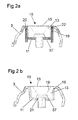
- Fig. 2a
- im Schnitt ausschnittsweise den Bereich des eingesetzten Schutzelementes mit zusätzlicher Haltevorrichtung als separates Bauteil,
- Fig. 2b
- im Schnitt ausschnittsweise den Bereich des eingesetzten Schutzelementes mit einer in-situ in der Schale aufgebauten Haltevorrichtung,
- Fig. 3
- den typischen Frequenzgang eines Im-Ohr Hörgerätes mit und ohne Membran bzw. Schutzelement,
- Fig. 4
- schematisch dargestellt einen möglichen Herstellprozess für die Herstellung eines Schutzelementes,
- Fig. 5
- ein Montagewerkzeug für das Montieren bzw. Wiederentfernen eines Schutzelementes in Perspektive,
- Fig. 6
- dasjenige Ende des Montagewerkzeuges geeignet für die Montage,
- Fig. 7
- dasjenige Ende des Montagewerkzeuges geeignet für das Wiederentfernen des Schutzelementes,
- Fig. 8a-c
- den Montagevorgang des Schutzelementes in die Gehäusewandung eines Im-Ohr Hörgerätes, und
- Fig. 9a-c
- das Wiederentfernen des Schutzelementes aus dem Gehäuse.
- Fig. 1a
- on average the standard structure of the eardrum end of an in-ear hearing aid with a protective element according to the invention,
- Fig. 1b
- a closed earphone module, which can be used in an in-ear hearing device or used as an external earpiece for a behind-the-ear device,
- Fig. 2a
- Sectionally section of the area of the protective element used with additional holding device as a separate component,
- Fig. 2b
- Sectionally section of the area of the protective element used with a holding device constructed in-situ in the shell,
- Fig. 3
- the typical frequency response of an in-ear hearing aid with and without membrane or protective element,
- Fig. 4
- schematically shows a possible manufacturing process for the production of a protective element,
- Fig. 5
- an assembly tool for mounting or removing a protective element in perspective,
- Fig. 6
- the end of the assembly tool suitable for mounting,
- Fig. 7
- that end of the assembly tool suitable for the removal of the protective element,
- Fig. 8a-c
- the assembly process of the protective element in the housing wall of an in-ear hearing aid, and
- Fig. 9a-c
- the removal of the protective element from the housing.
Figur 1a zeigt schematisch als Skizze den standardmässigen
Aufbau des trommelfellseitigen Endes eines Im-Ohr
Hörgerätes 1 mit einem in der Gehäusewandung 3
eingelassenen Membran-Cerumenschutz 10. Der Cerumenschutz
10 wird direkt in eine dafür vorgesehene Vertiefung 11 in
der Gehäusewandung oder Schale 3 eingelassen angeordnet.
Die Vertiefung 11 ist dabei integraler Bestandteil der
Gehäusewandung oder Schale 3 und wird mit der Schale
gemeinsam aufgebaut. Alternativ dazu kann die Vertiefung 11
auch als separates Bauteil 20 ausgestaltet sein, welches in
einer dafür vorgesehenen Bohrung 22 in der Schale 3
montiert wird, wie es in Figur 2a gezeigt ist. Am unteren
Ende der Vertiefung 11 befindet sich eine Öffnung 21 in die
der Schallleitungsschlauch 7 eingeklebt wird. Dieser
Schlauch hält auch den Hörer 5 in seiner Position fest. Der
Hörer 5 ist zusätzlich noch mit einer Lagerung 9 umgeben,
welche mechanische Schwingungen dämpfen soll. Schliesslich
erkennbar ist auch ein Ventilationsausgleichskanal 17 um
einen Druckausgleich mit dem Innenohr nach aussen zu
ermöglichen.FIG. 1a schematically shows a sketch of the standard one
Structure of the eardrum end of an in-
Die Figur 1b zeigt den entsprechenden Aufbau für ein
geschlossenes Hörermodul 4, welches in ein Im-Ohr Hörgerät
eingesetzt werden kann wie in US 6,813,364 B1 beschrieben,
oder welches als externer Lautsprecher eines
Hinterohrgerätes im Ohr verwendet werden kann. In diesem
Falle ist der Hörer 12 durch elastische Lagerungen 14 in
einem Gehäuse 6 eingeschlossen, welches eine
Schallaustrittsöffnung 11 aufweist, welche so ausgestaltet
ist, dass das Schutzelement 13 eingeführt werden kann und
damit die Membran 15 den äussersten Abschluss des Systems
bildet.FIG. 1b shows the corresponding structure for a
Insbesondere Figur 2b zeigt wiederum schematisch als Skizze
den Membran-Cerumenschutz 10 im Schnitt. Die Membran 15 ist
auf einem Träger 13 montiert, welcher in die Kavität 11
eingesetzt ist. Dabei hat die Kavität 11 die entsprechende
Tiefe, dass die Membran 15 bündig zur Gehäuseoberfläche zu
liegen kommt. Es ist auch zu erkennen, dass der Träger 13
aussen einen nicht konstanten Querschnitt 13 aufweist, d.h.
vorgesehen ist eine seitliche Abstufung 18, welche auf
einem entsprechenden Sattel in der Kavität 11 aufliegt
sowie eine innere Abstufung 57 welche das Auswechseln
ermöglicht. Die innere Öffnung des Trägers, insbesondere
vom kleinen Schlauchdurchmesser 21 zum grösseren äusseren
Durchmesser, überdeckt durch die Membran 15, verläuft
konisch. Die konische Oberfläche ist mit dem Bezugszeigen
19 versehen.In particular, Figure 2b again shows schematically as a sketch
the
Die skizzierte Erfindung geht alle oben besprochenen
Problemfelder an:
Figur 3 zeigt einen typischen Frequenzgang eines Im-Ohr Hörgerätes mit und ohne Membran. Es ist zu erkennen, dass durch die Membran eine breitbandige Dämpfung von ca. 2 dB zustande kommt. Dies ist auf die innere Dämpfung des Membranmaterials und die Trägheit der Membran zurückzuführen. Es muss also bei der Hörgeräteanpassung eine entsprechende Reserve zur Kompensation der Membrandämpfung berücksichtigt werden.FIG. 3 shows a typical frequency response of an in-ear Hearing aid with and without membrane. It can be seen that through the membrane a broadband attenuation of about 2 dB comes about. This is due to the inner damping of the Membrane material and the inertia of the membrane due. So it has to be in the hearing aid fitting a corresponding reserve for the compensation of Membrane damping are taken into account.
Figur 4 zeigt schematisch ein mögliches Aufbringen einer
Membran auf einen Träger 13 für die Herstellung eines
entsprechenden Schutzelementes 10. Auf einer Unterlage 31
wird eine Folie 33 aufgelegt, bestehend aus demjenigen
Polymer, welches geeignet ist zur Bildung der Membran.
Mittels eines Greifelementes 35 wird der Träger 13 gehalten
und gegen die auf der Unterlage 31 angeordnete Folie 33
abgesenkt.Figure 4 shows schematically a possible application of a
Membrane on a
Sobald der frontseitige Rand 37 des Trägers oder Körpers 13
auf der Folie 33 auftrifft, wird das Folienmaterial am Rand
37 angesintert bzw. angeschweisst. Dies kann entweder durch
Erhitzen der Folie 33 auf der Unterlage 31 erfolgen, oder
aber, durch Erhitzen des vorzugsweise aus einem
wärmeleitenden Material bestehenden Trägers 13. Durch das
Ansintern bzw. Anschweissen der Membran am Träger 13 wird
diese gleichzeitig aus der Folie 33 herausgelöst, worauf
das Greiforgan 35 wieder von der Unterlage 31 entfernt
werden kann. Nun ist die Membran 15 auf die Träger 33
angeordnet und das Schutzelement kann in die Kavität einer
Hörgerätewandung eingelassen werden. Dieser Vorgang soll
nun nachfolgend unter Bezug auf die Figuren 5 ff näher
beschrieben werden.Once the
Figur 5 zeigt in Perspektive ein Werkzeug bzw.
Montagewerkzeug 41, mittels welchem das CerumenschutzElement
sowohl in der Gehäusewandung angeordnet werden
kann, wie auch wieder von dieser entfernt werden kann. Das
Werkzeug weist zwei entsprechend ausgestaltete Enden 43 und
45 auf. Dabei zeigt Figur 6 dasjenige Ende 43, welches für
die Montage bzw. das Einbringen des Cerumenschutzes in der
Gehäusewandung vorgesehen ist. Hierzu weist das Werkzeug
ein kreisrundes zylinderartiges Ende 49 auf, welches in
etwa dem Durchmesser des oberen bzw. äusseren Randes 37 des
Cerumenschutzes entspricht. Etwas vom Ende zurückversetzt
ist ein elastischer Mantel 47 vorgesehen, welcher aussen
umgreifend das Ende 49 überragt. Dieser elastische Mantel
ist derart dimensioniert, dass ein Aussenumgreifen der
äusseren Kontur des oberen Randes 37 des Schutzelementes im
Bereich der Membran möglich ist. Der elastische Mantel 47
kann dabei aus dem gleichen Material bestehen wie das Ende
43 und durch entsprechende Ausgestaltung elastisch federnde
Eigenschaften haben, oder er kann aus einem
gummielastischen Material wie ein Elastomer oder ein
thermoplastisches Elastomer bestehen und als zusätzliches
Bauteil auf das Ende 43 montiert sein, oder integral mit
diesem aufgebaut sein, beispielsweise über ein 2K-Spritzgussverfahren.
Zur Vereinfachung wird in der
Beschreibung von einem Gummimantel gesprochen. Auf die
Montage selbst soll unter Bezug auf Figur 8 näher
eingegangen werden.FIG. 5 shows in perspective a tool or
Das entgegengesetzte Ende des Werkzeuges 41 ist in Figur 7
dargestellt, wo ein zylinderartiges Demontageelement 51 am
Ende 45 des Werkzeuges 41 angeordnet ist. Das
Demontageelement 51 weist vorzugsweise endständig ein
Einrastorgan 53 auf, auf dessen Funktion unter Bezug auf
Figur 9 näher eingegangen wird.The opposite end of the
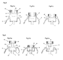
Figur 8 zeigt nun anhand der drei Darstellungen a), b) und
c) den Montagevorgang für das Einführen eines
Schutzelementes 10 in die Kavität 11 eines Im-Ohr
Hörgerätes. Dabei wird gemäss Figur 8a der Cerumenschutz
bzw. der Träger 13 durch den aussen umgreifenden
gummielastischen Mantel 47 des Werkzeuges 41 gehalten.
Figur 8b zeigt das Einfügen des Trägers 13 in die Kavität
11, wobei nun der aussen umgreifende Gummimantel 47 an der
Gehäusewandung 3 ansteht. Infolge der gummielastischen
Ausbildung kann der Mantel 47 beim Einführen des Trägers 13
zusammengedrückt werden, wie in Figur 8c dargestellt.
Sobald der Träger bzw. Körper zusammen mit der Membran,
d.h. das Cerumenschutzelement in der Kavität 11 vollständig
eingelassen ist, kann das Werkzeug 41 nach oben abgehoben
werden, ohne dass das Element wieder aus der Kavität 11
entfernt wird.FIG. 8 now shows with reference to the three representations a), b) and
c) the assembly process for the insertion of a
Das Wiederentfernen des Schutzelementes aus der Kavität 11
erfolgt mittels des anderen Endes des Werkzeuges 41, wie
schematisch unter Bezug auf die Figuren 9a und 9b erläutert
wird. Dabei wird das Demontageelement 51 mit dem
endständigen Einrastorgan 53 gegen die Membran 15 des
Schutzelementes bewegt, und zusammen mit der Membran gegen
die untere verjüngte Öffnung 21 im Körper bzw. Träger 13
gedrückt. Aufgrund der hohen Reissfestigkeit der Membran 15
wird diese nicht durchstossen bzw. durchtrennt sondern mit
dem Demontageelement 51 gedehnt, was vorteilhaft ist, um
eine Verschmutzung des Hörers in der Hörhilfe zu
verhindern. Sobald das Demontageelement 51 vollständig
eingeführt ist, rasten die seitlich vorstehenden
Einrastorgane 53 in entsprechenden Ausnehmungen 57 in der
inneren Wandung des Trägers 13 ein, womit nun das
Schutzelement aus der Kavität 11 herausgezogen werden kann.The removal of the protective element from the cavity 11th
takes place by means of the other end of the
Aufgrund der Ausgestaltung des Schutzelementes und unter Verwendung des Werkzeuges, dargestellt in den Figuren 5 bis 7, ist es auf einfache Art und Weise möglich den Cerumenschutz jederzeit zu ersetzen. Mit anderen Worten kann der Cerumenschutz auch durch eine Person ersetzt werden, welche die Hörhilfe benutzt. Due to the design of the protective element and under Use of the tool, shown in Figures 5 to 7, it is possible in a simple way the To replace cerumen protection at any time. In other words The cerumen protection can also be replaced by one person who uses the hearing aid.
Bei den in den Figuren 1 bis 9 dargestellten Vorrichtungen, Elemente und Werkzeuge handelt es sich selbstverständlich nur um Beispiele, welche auf x-beliebige Art und Weise abgeändert, modifiziert oder durch weitere Elemente ergänzt werden können. So ist es möglich, anstelle der genannten Polymermaterialien andere für die Herstellung der Membrane geeignete Materialien zu verwenden. Auch der Träger bzw. Körper des Cerumenschutzelementes kann aus x-beliebigen, geeigneten Materialien hergestellt werden, wobei vorzugsweise ein gut wärmeleitendes und wärmeresistentes Material, wie beispielsweise ein faserverstärktes Polymer verwendet wird, um ein vereinfachtes Aufbringen der Membran auf dem Träger zu ermöglichen, wie unter Bezug auf Figur 4 näher erläutert. Auch das Werkzeug, beschrieben unter Bezug auf die Figuren 5 bis 7, stellt lediglich ein Beispiel dar, das nicht zwingend stabartig ausgebildet sein muss. Es kann auch eine andere Werkzeugform verwendet werden, an welcher ein gummiartiges Material, wie beispielsweise eine Art Gummischlauch, angeordnet ist, um das Schutzelement im Hörgerät anzuordnen, und andererseits kann auch ein Demontageelement bzw. ein Greifelement vorgesehen sein, das beispielsweise endständig eine raue Kontur aufweist, um angreifend im inneren Konus des Trägers oder Körpers diesen wieder aus der Hörhilfe zu entfernen.In the devices shown in FIGS. 1 to 9, Of course, elements and tools are involved just for examples, which in any way modified, modified or supplemented by other elements can be. So it is possible, instead of the said Polymer materials others for the production of the membrane to use suitable materials. Also the carrier or Body of Cerumenschutzelementes can from x-arbitrary, suitable materials are produced, wherein preferably a good heat-conducting and heat-resistant Material, such as a fiber-reinforced polymer is used to simplify the application of the membrane on the support, as with reference to FIG. 4 explained in more detail. Also the tool, described with reference to Figures 5 to 7, is merely an example, that does not necessarily have to be rod-shaped. It can also be used a different tool shape on which a rubbery material, such as a kind Rubber hose, is arranged to protect the protective element in Hearing device to arrange, and on the other hand can also Disassembly or a gripping element may be provided, the For example, terminally has a rough contour to attacking in the inner cone of the wearer or body this to remove again from the hearing aid.
Claims (14)
Priority Applications (3)
| Application Number | Priority Date | Filing Date | Title |
|---|---|---|---|
| EP20050010122 EP1562400B1 (en) | 2005-05-10 | 2005-05-10 | Replaceable protective membrane of listening device of hearing-aids |
| DE200550004761 DE502005004761D1 (en) | 2005-05-10 | 2005-05-10 | Replaceable hearing protection membrane for hearing aids |
| DK05010122T DK1562400T3 (en) | 2005-05-10 | 2005-05-10 | Interchangeable hearing protection membrane for hearing aids |
Applications Claiming Priority (1)
| Application Number | Priority Date | Filing Date | Title |
|---|---|---|---|
| EP20050010122 EP1562400B1 (en) | 2005-05-10 | 2005-05-10 | Replaceable protective membrane of listening device of hearing-aids |
Publications (3)
| Publication Number | Publication Date |
|---|---|
| EP1562400A2 true EP1562400A2 (en) | 2005-08-10 |
| EP1562400A3 EP1562400A3 (en) | 2005-12-28 |
| EP1562400B1 EP1562400B1 (en) | 2008-07-23 |
Family
ID=34673779
Family Applications (1)
| Application Number | Title | Priority Date | Filing Date |
|---|---|---|---|
| EP20050010122 Active EP1562400B1 (en) | 2005-05-10 | 2005-05-10 | Replaceable protective membrane of listening device of hearing-aids |
Country Status (3)
| Country | Link |
|---|---|
| EP (1) | EP1562400B1 (en) |
| DE (1) | DE502005004761D1 (en) |
| DK (1) | DK1562400T3 (en) |
Cited By (7)
| Publication number | Priority date | Publication date | Assignee | Title |
|---|---|---|---|---|
| DE102006043153A1 (en) * | 2006-09-14 | 2008-03-27 | Siemens Audiologische Technik Gmbh | Cleaning tool for a hearing aid |
| EP2157815A1 (en) * | 2008-08-18 | 2010-02-24 | Siemens Medical Instruments Pte. Ltd. | Hearing aid with a converter protection device |
| EP2360948A3 (en) * | 2010-02-01 | 2012-10-31 | Siemens Medical Instruments Pte. Ltd. | Tool for assembling and removing an earpiece of a hearing aid |
| US8379899B2 (en) | 2004-11-01 | 2013-02-19 | Sonion Nederland B.V. | Electro-acoustical transducer and a transducer assembly |
| DE102011120391A1 (en) * | 2011-12-06 | 2013-06-06 | Valeo Schalter Und Sensoren Gmbh | Ultrasonic sensor for a motor vehicle, motor vehicle and method for producing an ultrasonic sensor |
| EP2515810B1 (en) | 2009-12-22 | 2017-04-26 | Dynamic Ear Company B.V. | Ear protector with a sound damping filter, sound damping filter for such an ear protector as well as method for manufacturing a sound damping filter for such an ear protector |
| WO2019105522A1 (en) * | 2017-11-28 | 2019-06-06 | Sonova Ag | Cerumen filter applicator |
Families Citing this family (1)
| Publication number | Priority date | Publication date | Assignee | Title |
|---|---|---|---|---|
| CN206181373U (en) | 2013-11-20 | 2017-05-17 | 索诺瓦公司 | A sound duct, sound duct are arranged, earphone and hearing equipment for earphone |
Citations (7)
| Publication number | Priority date | Publication date | Assignee | Title |
|---|---|---|---|---|
| DE3616637A1 (en) * | 1986-05-16 | 1987-11-19 | Siemens Ag | DEVICE FOR SCREWING ON A LID ON A SCREW CONNECTOR OF A HOUR DEVICE |
| US4972488A (en) * | 1987-04-13 | 1990-11-20 | Beltone Electronics Corporation | Ear wax barrier and acoustic attenuator for a hearing aid |
| DE4232317A1 (en) * | 1991-09-26 | 1993-05-13 | Unitron Ind Ltd | DEVICE FOR PROTECTION FROM LARGE EARS FOR A HOER DEVICE TO BE WEARED |
| WO2000003561A1 (en) * | 1998-07-10 | 2000-01-20 | Tøpholm & Westermann APS | An ear wax guard for an in-the-ear hearing aid and a means for use at insertion and removal hereof |
| US6134333A (en) * | 1998-03-17 | 2000-10-17 | Sonic Innovations, Inc. | Disposable oleophobic and hydrophobic barrier for a hearing aid |
| US6205227B1 (en) * | 1998-01-31 | 2001-03-20 | Sarnoff Corporation | Peritympanic hearing instrument |
| EP1434464A1 (en) * | 2002-12-23 | 2004-06-30 | Sonion Roskilde A/S | Encapsulated receiver comprising an expansible means such as a balloon |
-
2005
- 2005-05-10 DE DE200550004761 patent/DE502005004761D1/en active Active
- 2005-05-10 EP EP20050010122 patent/EP1562400B1/en active Active
- 2005-05-10 DK DK05010122T patent/DK1562400T3/en active
Patent Citations (7)
| Publication number | Priority date | Publication date | Assignee | Title |
|---|---|---|---|---|
| DE3616637A1 (en) * | 1986-05-16 | 1987-11-19 | Siemens Ag | DEVICE FOR SCREWING ON A LID ON A SCREW CONNECTOR OF A HOUR DEVICE |
| US4972488A (en) * | 1987-04-13 | 1990-11-20 | Beltone Electronics Corporation | Ear wax barrier and acoustic attenuator for a hearing aid |
| DE4232317A1 (en) * | 1991-09-26 | 1993-05-13 | Unitron Ind Ltd | DEVICE FOR PROTECTION FROM LARGE EARS FOR A HOER DEVICE TO BE WEARED |
| US6205227B1 (en) * | 1998-01-31 | 2001-03-20 | Sarnoff Corporation | Peritympanic hearing instrument |
| US6134333A (en) * | 1998-03-17 | 2000-10-17 | Sonic Innovations, Inc. | Disposable oleophobic and hydrophobic barrier for a hearing aid |
| WO2000003561A1 (en) * | 1998-07-10 | 2000-01-20 | Tøpholm & Westermann APS | An ear wax guard for an in-the-ear hearing aid and a means for use at insertion and removal hereof |
| EP1434464A1 (en) * | 2002-12-23 | 2004-06-30 | Sonion Roskilde A/S | Encapsulated receiver comprising an expansible means such as a balloon |
Cited By (13)
| Publication number | Priority date | Publication date | Assignee | Title |
|---|---|---|---|---|
| US8379899B2 (en) | 2004-11-01 | 2013-02-19 | Sonion Nederland B.V. | Electro-acoustical transducer and a transducer assembly |
| DE102006043153A1 (en) * | 2006-09-14 | 2008-03-27 | Siemens Audiologische Technik Gmbh | Cleaning tool for a hearing aid |
| EP2157815A1 (en) * | 2008-08-18 | 2010-02-24 | Siemens Medical Instruments Pte. Ltd. | Hearing aid with a converter protection device |
| US8233649B2 (en) | 2008-08-18 | 2012-07-31 | Siemens Medical Instruments Pte. Ltd. | Hearing aid device with a transducer protection facility |
| EP3195839B1 (en) | 2009-12-22 | 2022-04-06 | Sonova AG | Ear protector with a sound damping filter, sound damping filter for such an ear protector |
| EP2515810B1 (en) | 2009-12-22 | 2017-04-26 | Dynamic Ear Company B.V. | Ear protector with a sound damping filter, sound damping filter for such an ear protector as well as method for manufacturing a sound damping filter for such an ear protector |
| EP2360948A3 (en) * | 2010-02-01 | 2012-10-31 | Siemens Medical Instruments Pte. Ltd. | Tool for assembling and removing an earpiece of a hearing aid |
| US8355519B2 (en) | 2010-02-01 | 2013-01-15 | Siemens Medical Instruments Pte. Ltd. | Tool for fitting and removing a receiver of a hearing aid |
| DE102011120391A1 (en) * | 2011-12-06 | 2013-06-06 | Valeo Schalter Und Sensoren Gmbh | Ultrasonic sensor for a motor vehicle, motor vehicle and method for producing an ultrasonic sensor |
| CN111557099A (en) * | 2017-11-28 | 2020-08-18 | 索诺瓦公司 | Earwax filter applicator |
| US11190888B2 (en) | 2017-11-28 | 2021-11-30 | Sonova Ag | Cerumen filter applicator |
| WO2019105522A1 (en) * | 2017-11-28 | 2019-06-06 | Sonova Ag | Cerumen filter applicator |
| CN111557099B (en) * | 2017-11-28 | 2022-04-26 | 索诺瓦公司 | Earwax filter applicator |
Also Published As
| Publication number | Publication date |
|---|---|
| DE502005004761D1 (en) | 2008-09-04 |
| EP1562400A3 (en) | 2005-12-28 |
| DK1562400T3 (en) | 2008-11-10 |
| EP1562400B1 (en) | 2008-07-23 |
Similar Documents
| Publication | Publication Date | Title |
|---|---|---|
| EP1562400B1 (en) | Replaceable protective membrane of listening device of hearing-aids | |
| DE102006008044B3 (en) | In-the-ear hearing aid, has ventilation channel with openings in first- and second-housing zones | |
| EP0310866B1 (en) | Device for closing the apertures of hearing aids or earpieces for hearing aids | |
| DE102008038213B3 (en) | Hearing aid with a transformer protection device | |
| DE102007037024A1 (en) | Hearing device with elastically mounted handset | |
| EP0835042A2 (en) | Protection device for in and out sound apertures of housings or earpieces of hearing aids | |
| DE10214189B4 (en) | Device for sonicating an eardrum with a cerumen protection device and hearing aid | |
| EP3068147B1 (en) | Hearing aid with a cerumen protection device and cerumen protection device | |
| DE3413067C1 (en) | Hearing aid earmold end piece and hearing aid earmold on the hearing side | |
| DE202018107152U1 (en) | Ear plugs with rubble barrier for acoustic devices | |
| EP1993323B1 (en) | Earpiece for a hearing aid with bayonet fixing | |
| DE202018107452U1 (en) | Earsolive filled with fluid | |
| EP0821543A2 (en) | Membrane as outer surface of a hearing aid which is individualised by moulding a body | |
| EP2007172B1 (en) | Sound emitting pipes with 2 component design | |
| WO1995015067A1 (en) | Sheath for hearing aids, hearing aids or parts thereof provided therewith, hearing test process and device | |
| EP3481084B1 (en) | Hearing aid | |
| EP2557816A2 (en) | Assembly of a signal processing component in a housing of a hearing aid | |
| EP1718112A1 (en) | Hearing aid within an ear microphone | |
| DE102014200605A1 (en) | Dome with cerumen protection | |
| EP0821541A2 (en) | Hearing aid which is to be worn completely in the ear canal and which is individualised by moulding a body | |
| EP1906703A1 (en) | Otoplastic with connecting device | |
| DE102007025446B3 (en) | Ear piece for a hearing device with retaining ring | |
| DE1270616B (en) | Electronic hearing aid device to be worn in the ear | |
| DE10104129A1 (en) | Hearing aid incorporates a preferably changeable filter unit which prevents entry of moisture and/or dirt, in particular, cerumen, and includes a filter element constituted as a membrane and/or a sieve | |
| EP3614697B1 (en) | Elastic damping element for a receiver of a hearing device and hearing device comprising such a damping element |
Legal Events
| Date | Code | Title | Description |
|---|---|---|---|
| PUAI | Public reference made under article 153(3) epc to a published international application that has entered the european phase |
Free format text: ORIGINAL CODE: 0009012 |
|
| AK | Designated contracting states |
Kind code of ref document: A2 Designated state(s): AT BE BG CH CY CZ DE DK EE ES FI FR GB GR HU IE IS IT LI LT LU MC NL PL PT RO SE SI SK TR |
|
| AX | Request for extension of the european patent |
Extension state: AL BA HR LV MK YU |
|
| PUAL | Search report despatched |
Free format text: ORIGINAL CODE: 0009013 |
|
| AK | Designated contracting states |
Kind code of ref document: A3 Designated state(s): AT BE BG CH CY CZ DE DK EE ES FI FR GB GR HU IE IS IT LI LT LU MC NL PL PT RO SE SI SK TR |
|
| AX | Request for extension of the european patent |
Extension state: AL BA HR LV MK YU |
|
| 17P | Request for examination filed |
Effective date: 20060621 |
|
| AKX | Designation fees paid |
Designated state(s): CH DE DK LI |
|
| 17Q | First examination report despatched |
Effective date: 20061004 |
|
| 17Q | First examination report despatched |
Effective date: 20061004 |
|
| GRAP | Despatch of communication of intention to grant a patent |
Free format text: ORIGINAL CODE: EPIDOSNIGR1 |
|
| GRAS | Grant fee paid |
Free format text: ORIGINAL CODE: EPIDOSNIGR3 |
|
| GRAA | (expected) grant |
Free format text: ORIGINAL CODE: 0009210 |
|
| AK | Designated contracting states |
Kind code of ref document: B1 Designated state(s): CH DE DK LI |
|
| REG | Reference to a national code |
Ref country code: CH Ref legal event code: NV Representative=s name: TROESCH SCHEIDEGGER WERNER AG Ref country code: CH Ref legal event code: EP |
|
| REF | Corresponds to: |
Ref document number: 502005004761 Country of ref document: DE Date of ref document: 20080904 Kind code of ref document: P |
|
| REG | Reference to a national code |
Ref country code: DK Ref legal event code: T3 |
|
| PLBE | No opposition filed within time limit |
Free format text: ORIGINAL CODE: 0009261 |
|
| STAA | Information on the status of an ep patent application or granted ep patent |
Free format text: STATUS: NO OPPOSITION FILED WITHIN TIME LIMIT |
|
| 26N | No opposition filed |
Effective date: 20090424 |
|
| REG | Reference to a national code |
Ref country code: DE Ref legal event code: R084 Ref document number: 502005004761 Country of ref document: DE |
|
| PGFP | Annual fee paid to national office [announced via postgrant information from national office to epo] |
Ref country code: DK Payment date: 20230530 Year of fee payment: 19 Ref country code: DE Payment date: 20230530 Year of fee payment: 19 Ref country code: CH Payment date: 20230610 Year of fee payment: 19 |