EP1562303B1 - Signaltrenner - Google Patents
Signaltrenner Download PDFInfo
- Publication number
- EP1562303B1 EP1562303B1 EP05250559.1A EP05250559A EP1562303B1 EP 1562303 B1 EP1562303 B1 EP 1562303B1 EP 05250559 A EP05250559 A EP 05250559A EP 1562303 B1 EP1562303 B1 EP 1562303B1
- Authority
- EP
- European Patent Office
- Prior art keywords
- signal
- sampling
- signals
- separator
- output
- Prior art date
- Legal status (The legal status is an assumption and is not a legal conclusion. Google has not performed a legal analysis and makes no representation as to the accuracy of the status listed.)
- Expired - Lifetime
Links
Images


Classifications
-
- H—ELECTRICITY
- H04—ELECTRIC COMMUNICATION TECHNIQUE
- H04L—TRANSMISSION OF DIGITAL INFORMATION, e.g. TELEGRAPHIC COMMUNICATION
- H04L25/00—Baseband systems
- H04L25/02—Details ; arrangements for supplying electrical power along data transmission lines
- H04L25/03—Shaping networks in transmitter or receiver, e.g. adaptive shaping networks
- H04L25/03006—Arrangements for removing intersymbol interference
- H04L25/03178—Arrangements involving sequence estimation techniques
- H04L25/03248—Arrangements for operating in conjunction with other apparatus
- H04L25/0328—Arrangements for operating in conjunction with other apparatus with interference cancellation circuitry
-
- H—ELECTRICITY
- H04—ELECTRIC COMMUNICATION TECHNIQUE
- H04L—TRANSMISSION OF DIGITAL INFORMATION, e.g. TELEGRAPHIC COMMUNICATION
- H04L25/00—Baseband systems
- H04L25/02—Details ; arrangements for supplying electrical power along data transmission lines
- H04L25/03—Shaping networks in transmitter or receiver, e.g. adaptive shaping networks
- H04L25/03006—Arrangements for removing intersymbol interference
- H04L25/03178—Arrangements involving sequence estimation techniques
- H04L25/03248—Arrangements for operating in conjunction with other apparatus
- H04L25/03254—Operation with other circuitry for removing intersymbol interference
-
- H—ELECTRICITY
- H04—ELECTRIC COMMUNICATION TECHNIQUE
- H04L—TRANSMISSION OF DIGITAL INFORMATION, e.g. TELEGRAPHIC COMMUNICATION
- H04L25/00—Baseband systems
- H04L25/02—Details ; arrangements for supplying electrical power along data transmission lines
- H04L25/03—Shaping networks in transmitter or receiver, e.g. adaptive shaping networks
- H04L25/03006—Arrangements for removing intersymbol interference
- H04L25/03178—Arrangements involving sequence estimation techniques
- H04L25/03248—Arrangements for operating in conjunction with other apparatus
- H04L25/03292—Arrangements for operating in conjunction with other apparatus with channel estimation circuitry
-
- H—ELECTRICITY
- H04—ELECTRIC COMMUNICATION TECHNIQUE
- H04B—TRANSMISSION
- H04B2201/00—Indexing scheme relating to details of transmission systems not covered by a single group of H04B3/00 - H04B13/00
- H04B2201/69—Orthogonal indexing scheme relating to spread spectrum techniques in general
- H04B2201/707—Orthogonal indexing scheme relating to spread spectrum techniques in general relating to direct sequence modulation
- H04B2201/70703—Orthogonal indexing scheme relating to spread spectrum techniques in general relating to direct sequence modulation using multiple or variable rates
-
- H—ELECTRICITY
- H04—ELECTRIC COMMUNICATION TECHNIQUE
- H04L—TRANSMISSION OF DIGITAL INFORMATION, e.g. TELEGRAPHIC COMMUNICATION
- H04L25/00—Baseband systems
- H04L25/02—Details ; arrangements for supplying electrical power along data transmission lines
- H04L25/03—Shaping networks in transmitter or receiver, e.g. adaptive shaping networks
- H04L25/03006—Arrangements for removing intersymbol interference
- H04L2025/0335—Arrangements for removing intersymbol interference characterised by the type of transmission
- H04L2025/03375—Passband transmission
-
- H—ELECTRICITY
- H04—ELECTRIC COMMUNICATION TECHNIQUE
- H04L—TRANSMISSION OF DIGITAL INFORMATION, e.g. TELEGRAPHIC COMMUNICATION
- H04L25/00—Baseband systems
- H04L25/02—Details ; arrangements for supplying electrical power along data transmission lines
- H04L25/03—Shaping networks in transmitter or receiver, e.g. adaptive shaping networks
- H04L25/03006—Arrangements for removing intersymbol interference
- H04L2025/03433—Arrangements for removing intersymbol interference characterised by equaliser structure
- H04L2025/03439—Fixed structures
- H04L2025/03445—Time domain
- H04L2025/03471—Tapped delay lines
- H04L2025/03484—Tapped delay lines time-recursive
- H04L2025/0349—Tapped delay lines time-recursive as a feedback filter
Definitions
- the present invention relates to a signal separator used in a wireless receiver.
- interference cancellers for this purpose. In fact, interference cancellation is attracting attention as a technique that can increase system capacity.
- FIG. 1 is a block diagram of a conventional interference canceller 300, which is generally installed in a receiver in a wireless communications system.
- This type of interference canceller is called a replica generation type interference canceller because it generates a replica of the received signal and separates a desired wave from other signals (interference waves).
- the channel estimator 318 estimates the level fluctuation and phase rotation in the channels of the desired wave and the interference wave.
- the coefficient-variable filters 314 and 315 generate desired signal replicas and interference signal replicas, respectively, for all possible candidates of symbol sequence.
- Each of the desired signal replica and the interference signal replica can be generated by calculating convolution of every possible candidate of the symbol sequence and the estimated channel value.
- the adder 316 adds one of the desired signal replicas to one of the interference signal replicas to produce a set of received signal replicas.
- the maximum likelihood sequence estimator 320 determines a pair of symbol sequence candidates of the desired signal and the interference signal that provide the received signal replica closest to the actually received signal.
- the maximum likelihood sequence estimator 320 outputs the symbol sequence candidate of the desired wave as the determination result, thereby removing the interference.
- An interference canceller used in a multi-rate transmission system is also proposed in, for example, Japanese Patent Laid-Open Publication No. 11-251959A .
- signals are received at an array antenna in a DS-CDMA system using both a high-speed channel with a high transmission rate and a low-speed channel with a low transmission rate.
- An array antenna interference replica generation unit is provided to generate an interference replica of the high-speed channel for the purposes of removing the interference due to the high-speed channel from the received signal, and of improving the transmission quality of the low-speed channel.
- the conventional interference canceller of the replica generation type can remove interference by generating replicas of the desired signal and the interference signal.
- the conventional technique is based on the assumption that the band widths of the desired wave and the interference wave are the same, sufficient effect of interference cancellation cannot be achieved if a desired wave requiring a wide band and an interference wave expecting a narrow band are combined to form the received signal.
- combinations of a wide-band signal and a narrowband signal have to be avoided at the same frequency.
- JP 10178373A deals with the problem of separating a desired and an interference waveform in the case their sampling clocks do not match (e.g. they have different bandwidths and therefore they have to be sampled at different rates in order to fulfil the sampling theorem).
- the received signal is sampled at a prescribed sampling timing (1/2 of the symbol period).
- a replica signal (75) is generated, after having estimated a transmission line characteristic value and symbol candidates for both desired and interference waveforms.
- the replica signal is then subtracted to the (filtered) received signal (36).
- the residual (error) signal is sent to a likelihood information extraction group (37 and 38) for estimating the symbol sequences by use of the Viterbi algorithm (38).
- the invention provides a signal separator as defined in Claim 1.
- the present invention can provide a signal separator that functions in the circumstances where wide-band signals and narrowband signals coexist at the same frequency, and can remove an interference wave with a bandwidth different from the desired signal.
- the signal sequence of the transmitted signal is estimated accurately because the replica is generated for each group of the sampled signal designated by the index signal, preventing degradation of replica generating accuracy due to variation in possible signal points depending on different sampling timing.
- the signal separator further comprises:
- the signal separator further comprises:
- the estimated channel value is generated for each group of sampled signals, and the replica is generated using the channel estimation value produced according to the index value and the signal point candidate.
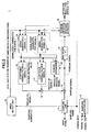
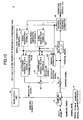
- FIG. 2 is a block diagram of a signal separator 1 according to the first embodiment of the invention.
- the signal separator 1 is suitably used in a wireless communication system in which multiple wireless transmitters using different symbol rates of transmission signals and multiple wireless receivers coexist and communicate with each other at the same frequency band.
- the signal separator 1 is installed in wireless receivers, regardless of whether in mobile stations or fixed stations.
- the signal separator 1 includes a sampling unit 11, a sampling controller 12, an index output unit 13, a first signal generator 14, a second signal generator 15, a first coefficient-variable filter 16, a second coefficient-variable filter 17, an adder 18, a subtractor 19, a channel estimator 20, a multiplier 21, and a maximum likelihood sequence estimator 22.
- the signal input to the signal separator 1 is a baseband signal, which has been subjected to bandlimiting at rolloff filters or the like.
- a baseband signal which has been subjected to bandlimiting at rolloff filters or the like.
- signals 1 and signal 2 contained in the received signal are illustrated.
- the signal input to the signal separator 1 is first supplied to the sampling unit 11.
- the input signal is sampled according to the sampling timing designated by the sampling controller 12, and output as discrete time signals.
- the sampling controller 12 outputs sampling timing information to the sampling unit 11, in accordance with the symbol rates of the multiple signals in the received signal (symbol rate f s1 of signal 1 and symbol rate f s2 of signal 2).
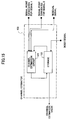
- FIG. 3 is a block diagram of the sampling unit 11 used in the signal separator 1.
- the sampling unit 11 includes a first sampling processor 31, a second sampling processor 32, a switching controller 33, and a switch 34.
- the signal input to the sampling unit 11 is supplied to the first sampling processor 31 and the second sampling processor 32 in parallel, and sampled at the sampling timing designated by the sampling controller 12 according to the symbol rate of the signal.
- the sampled signals are supplied to the switch 34.
- the switching controller 33 controls the switch 34 based on the sampling timing information supplied from the sampling controller 12 based on the symbol rate, such that the sample values are output from the switch 34 in order of time. Consequently, the input signal is sampled at uneven intervals and output to the next component.
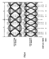
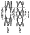
- FIG. 4 is a diagram illustrating the eye patterns of signal 1 and signal 2 sampled at uneven intervals by the sampling unit 11, together with the sampling timing and index given to each of the sampled signals.
- the signal is ideally sampled at the center or the widest point of the eye pattern (at the eye opening timing) for simplification purposes, and that the ratio of the symbol rate of signal 1 to signal 2 is 2/3.
- the relation between the sampling timing and the index given to each of the sampled signal is described below.
- the sampling controller 12 controls the sampling unit 11 such that the received signals are sampled at the associated sampling timing according to the symbol rates of the received signals, and that the sampled signals are output in time series.
- This arrangement allows the signal points of the received signals to be distributed in the signal space so as to easily separate the received signals from each other.
- the signals can be sampled at a prescribed sampling frequency, as illustrated in the flowchart of FIG. 5 .
- the least common multiple (LCM) of the symbol rates of multiple signals is determined, and a sampling frequency is selected so as to sample the signals at a rate of an integral multiple of the LCM. Since the signals are sampled at even intervals, this method is referred to as an even-interval sampling method.
- step S1 the least common multiple f LCM of the symbol rates of multiple signals is determined. Then, in step S2, each of the symbol rates of the multiple signals is compared with the LCM rate f LCM , according to formula f LM ⁇ f sk for k ⁇ ? where k is an integer greater than or equal to 1, and ⁇ denotes all the symbol rates of the multiple signals.
- each of the symbol rates (f s1 , f s2 , ...) is compared with f LCM , and it is determined whether the formula is satisfied. If the least common multiple f LCM agrees with the highest symbol rate among the multiple signals (NO in step S2), the process proceeds to step S4, and the sampling frequency is set to ⁇ times f LCM (where ⁇ is an integer greater than or equal to 2). In this case, the sampling controller 12 instructs the sampling unit 11 to sample the input signal at a rate of ⁇ *f LCM . Because the input signal is sampled at a sampling frequency greater than or equal to twice the symbol rate of any received signal, the signal waveform can be reproduced accurately even under the environment in which synchronization is not guaranteed.
- step S2 If it is determined that the least common multiple f LCM of the symbol rate does not agree with any of the symbol rates of the multiple signals (YES in step S2), the process proceeds to step S3, and the sampling frequency is set to f LCM .
- a single sampling unit is sufficient to carry out the even-interval sampling method, and therefore, the structure of the signal separator can be simplified.
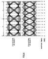
- FIG. 6 is a diagram illustrating the eye patterns of signal 1 and signal 2, together with the sampling timing and the index given to each of the sampled signals, obtained using the even-interval sampling method. Similar to the example shown in FIG. 4 , the ratio f s1 /f s2 of the symbol rate of signal 1 to that of signal 2 is 2/3. The sampling frequency becomes 3f s1 , which equals 2f s2 . The index is given to each of the signals sampled at even intervals.
- the sampling controller 12 outputs a sampling control signal so as to cause the sampling unit 11 to sample the received signal according to a rate equal to a common multiple of the symbol rates of multiple received signals.
- the sampling rate is determined in a simple manner, and sampling of the received signal is implemented with the sample structure.
- the sampling unit 11 supplies the sampling counts n1 to the index output unit 13 when sampling the input signal, while it supplies the sampled signal to the subtractor 19. Even if the same symbols are received, it is improper for the sampled signals output from the sampling unit 11 to be treated equally because the signal point (or constellation point) varies due to the inter-symbol interference under the influence of the bandlimiting filter, depending on the sampling timing.
- the index output unit 13 is configured to group the sampled signals into multiple categories, based on the sampling counts, such that the sampled signals grouped in the same category have similar signal characteristics according to the sampling timing.
- the operation of the index output unit 13 is explained in conjunction with FIG. 4 . Since in this example the symbol rate ratio of signal 1 to signal 2 is 2/3, time required for two symbols of signal 1 is equal to time required for three symbols of signal 2. This time span is denoted as T.
- the received signal which is a combination of signal 1 and signal 2, will have the same characteristic every time period T.
- signals sampled at sampling timing 0 and sampling timing 0' are separate from each other by time T, and these two sampled signals can be treated as the signals with similar characteristics belonging to the same group.
- signals sampled at time 1 and time 1' are treated as the same group.
- the index output unit 13 gives the same index to the same group, and outputs the index signals representing the signal groups.
- the calculated index is output as index signals, and supplied to the signal generators 14 and 15, and to the maximum likelihood sequence estimator 22.
- Each of the signal generators 14 and 15 outputs a signal point (constellation point) corresponding to the index signal for every possible candidate of symbol sequence.
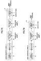
- FIG. 7A and FIG. 7B are examples of the signal generator 14. Since the signal generator 14 and signal generator 15 operate in the same manner with the same structure, explanation is made of only the signal generator 14 for signal 1.
- the signal generator 14 may have either structure shown in FIG. 7A or FIG. 7B .
- the symbol generator 41 generates all possible candidates of symbol sequence.
- the modulator 42 modulates each of the symbol sequence candidates.
- the modulated symbol sequences are subjected to bandlimiting at the root rolloff filters 43 or 44, and sampled at the sampling circuit 45 according to the sampling timing designated by the sampling controller 12. Then the sampling result is output from the signal generator 14.
- the symbol generator 51 generates all possible candidates of symbol sequence.
- the modulator 52 modulates each of the symbol sequence candidates.
- the modulated symbol sequences are subjected to bandlimiting at the bandlimiting filter 53, and sampled at the sampling circuit 54 according to the sampling timing designated by the sampling controller 12.
- the sampling result is output from the signal generator 14.
- bandlimiting filtering is performed at the receiving end for each of the symbol rates.
- the filter used at the transmitting end and the filter used at the receiving end are cascaded, as illustrated in FIG. 7A , and sampling is performed after the filtering.
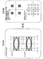
- FIG. 8B illustrates the signal point candidates output from the signal generator 14 shown in FIG. 7A , on the condition that the limiting band of the transmission filter and that of the receiving filter are different from each other, and that the limiting bandwidth of the transmission filter is narrower than that of the receiving filter.
- FIG. 8A illustrates the signal waveforms (eye patterns) having passed through the second root rolloff filter 44 on I channel (top) and Q channel (bottom).
- the sampling rate is three times as high as the symbol rate, and sampling is performed at timing indicated by the dashed line.
- the post-sampling constellation of the signal point candidates becomes one shown in FIG. 8B .
- FIG. 9A illustrates the signal waveforms (eye patterns) having passed through the bandlimiting filter 53 of the signal generator 14 shown in FIG. 7B .
- FIG. 9B illustrates the constellation of the signal point candidates output from the sampling circuit 54.
- the signal generator 14 produces signal waveforms that are not influenced by noise or fading for all the symbol sequence candidates, samples the signal waveforms at prescribed sampling timing designated by the sampling controller 12, and outputs a set of signal point candidates on the signal space.
- the signal point candidates generated by the signal generator 14 are input to the coefficient-variable filter 16 for signal 1.
- the signal point candidates generated by the signal generator 15 are input to the coefficient-variable filter 17 for signal 2. Since the basic structures of the coefficient-variable filters 16 and 17 are the same, explanation is made using the coefficient-variable filter 16 as an example.
- a filter coefficient is set according to the instruction from the channel estimator 20 so as to reproduce the level fluctuation and phase rotation due to the influence of fading or the like in each of multiple signals.
- the coefficient-variable filter 16 has multiple taps for inputting the coefficients, and generates a replica of a delayed wave.
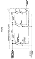
- FIG. 10 is a block diagram of the coefficient-variable filter 16.
- the coefficient-variable filter 16 has 1-symbol delay circuits 61 1 through 61 n , through which a sequence of signal point candidates including the signal point candidates for 1-symbol delayed wave is input. Phase and level adjustment is performed on the signal point candidate sequence by a set of variable phase shifters 62 1 through 62 n and a set of variable amplifiers 63 1 through 63 n . The phase and level adjusted signal points are summed up at the adder 64 to generate the replica of signal 1 containing the 1-symbol delayed wave.
- variable phase shifters 62 1 through 62 n and the variable amplifiers 63 1 through 63 n are controlled by the estimated channel value output from the channel estimator 20. Similarly, a replica of signal 2 is generated by the coefficient-variable filter 17.
- replicas of multiple signals When the replicas of multiple signals are generated, these replicas are added to each other to produce a replica of the received signal that is a combination of the multiple signals.
- the coefficient-variable filter 16 is furnished with multiple taps for inputting coefficients so as to deal with the signal containing the delayed wave arriving in a time-spread manner, and outputs a replica of the received signal containing the delayed wave. Since the delayed wave is taken into account when producing the replica of the received signal, a more accurate replica of the received signal can be produced.
- the replica of the received signal is supplied to the subtractor 19, which subtracts the replica of the received signal from the input and sampled received signal to produce a residual signal.
- the residual signal is supplied to the multiplier 21 and the channel estimator 20.
- the multiplier 21 multiplies the input residual signal by itself (or by the complex conjugate if the input residual signal is a complex number), and outputs the multiplication result to the maximum likelihood sequence estimator 22.
- the maximum likelihood sequence estimator 22 estimates the transmitted symbol sequences of the multiple signals simultaneously, using a state transition diagram, on the basis of the multiplication result of the residual signal supplied from the multiplier 21, and outputs the estimation result.
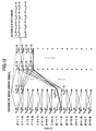
- An example of the state transition diagram is shown in FIG. 11 .
- FIG. 11 is a trellis diagram created based on the state transition diagram representing the operation of the maximum likelihood sequence estimator 22.
- the example shown in FIG. 11 is on the assumption that there is no delay wave and BPSK modulation is employed.
- the symbol rate ratio of signal 1 to signal 2 is 1/3, which means that three symbols of signal 2 are transmitted, while a symbol of signal 1 is transmitted.
- the symbols in the bracket shown in FIG. 11 represent [(the state of the desired wave); (the state of the interference wave)]..
- signal 2 can be ideally sampled at timing without inter-symbol interference, as illustrated in FIG. 19B , the state of signal 2 becomes noncorrelated with the previous and next symbols at sampling timing, and therefore, the state with inter-symbol interference does not have to be considered for signal 2.
- one-symbol time of signal 1 is longer, as compared with signal 2. Accordingly, if signal 1 is sampled in accordance with a high-symbolrate signal, such as signal 2, signal points containing inter-symbol interference components, as illustrated in FIG. 19A , have to be taken into account. In this case, signal 1 is subjected to inter-symbol interference from the previous and next symbols along the time axis (not only past symbols, but also future symbols with respect to the current symbol), as illustrated in FIG. 20 . For this reason, it is desired to define the state of signal 1 using past symbols, the present symbol, and future symbols.
- the total of five symbols including two past symbols, one current symbol, and two future symbols, are considered.
- one-symbol time of signal 1 agrees with three-symbol time of signal 2. Accordingly, signal 2 changes its state three times, while signal 1 changes the state once. Since state transition of signal 1 takes the inter-symbol interference into account, only those state transition taking into account the past and future symbols are considered. For example, the state changes from "001" only to "010" and "011". To sum up, if only signal 2 changes its state, without state transition of signal 1, the relation a ⁇ 1 a 2 a 3 * ⁇ 01 02 a 3 * * stands, where symbols "*" and "**" are either 0 or 1.
- next state that can possibly occur is limited depending on the previous state and time, and accordingly, the trellis diagram shown in FIG. 11 can be created based on the state transition diagram.
- the arrows depicted in FIG. 11 to indicate the availability of state transition are called "paths".
- the output of the multiplier 21, which is the absolute square of the residual signal input to the multiplier 21, is stored as the state transition reference, in association with each state (each symbol candidate), in the maximum likelihood sequence estimator 22.
- the maximum likelihood sequence estimator 22 adds this residual signal to the accumulations of the past errors in all possible paths, and sums them up. For example, if the error in state [n, m] at time k is w n,m (k), as illustrated in FIG.
- the accumulated error in state [111, 1] at time (k+3) becomes w 1 , 1 k + w 1 , 1 ⁇ k + 1 + w 1 , 1 ⁇ k + 2 + w 1 , 1 ⁇ k + 3 w 1 , 1 k + w 1 , 1 ⁇ k + 1 + w 1 , 0 ⁇ k + 2 + w 1 , 1 ⁇ k + 3 ⁇ w 5 , 0 k + w 5 , 0 ⁇ k + 1 + w 1 , 1 ⁇ k + 2 + w 1 , 1 ⁇ k + 3
- This calculation is made for all the states, and a path with the minimum accumulated error is determined.
- the maximum likelihood sequence estimator estimates that the symbol sequence that defines the path with the minimum accumulated error is transmitted, and outputs the estimation result for each of the multiple signals contained in the received signal.
- the output timings of the estimation results for signal 1 and signal 2 are designated by the indexes supplied from the index output unit 13.
- the timing for outputting the estimation result may be determined based on the buffer size of the maximum likelihood sequence estimator 22.
- the maximum likelihood sequence estimator 22 supplies symbols that give the replica signals closest to the received signal to the signal generators 14 and 15, respectively.
- Each of the signal generators 14 and 15 supplies the signal point corresponding to the input symbol to the channel estimator 20.
- the channel estimator 20 uses the signal point and the residual signal supplied from the subtractor 19 to estimate the channel of the received signal, including its delay components, based on the adaptive algorithm, and controls the filter coefficient of each of the coefficient-variable filters 16 and 17.
- the sampled signals are classified by the indexes output from the index output unit 13, and candidates of the signal point are generated according to the classification to separate signals.
- index signals are used to classify the signals and remove interference signals from the received signal.
- the signal separator 1 can prevent degradation of accuracy in generating the replica due to variation in possible signal point candidates due to difference in sampling timing, and accordingly, multiple signals with different symbol rates can be transmitted in the same frequency band in the system using the signal separator of the first embodiment. In other words, even if multiple systems coexist in the same frequency band, the frequency utilization efficiency can be improved by employing the signal separator of the first embodiment.
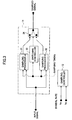
- FIG. 13 is a block diagram of the signal separator 2 according to the second embodiment.
- the operation of the channel estimator differs, and the other functions are the same. Focusing is made mainly on the difference, that is, the operations and structures of the signal generator and the channel estimator, and explanation for the unchanged parts is omitted.
- the same components as those in the first embodiment are denoted by the same reference numbers.
- FIG. 14 is a block diagram of the signal generator 101 used in the signal separator 2, which is a conventional signal generator including a symbol generator 111 and a modulator 112.
- the symbol generator 111 generates a set of symbol candidates.
- the modulator 112 modulates each of the symbol candidates, and outputs signal point candidates without inter-symbol interference, like a conventional interference canceller.
- the signal generator 14 outputs the signal point candidates on the signal space, corresponding to the indexes supplied from the index output unit 13.
- the indexes are supplied from the index output unit 13 to the channel estimator 103, and the channel estimator 103 estimates the inter-symbol interference generated at sampling timing when estimating the level fluctuation and phase rotation in the channel.
- the channel estimator 103 of the second embodiment has a storage 122 and a channel estimation circuit 121, as illustrated in FIG. 15 .
- the storage is configured to store estimated channel values (i.e., the estimation results made by the channel estimator 103) in association with the corresponding indexes.
- estimated channel value is produced independently for each of the indexes.
- the channel estimator 103 Upon receiving an index signal from the index output unit 13, the channel estimator 103 searches in the storage 122 for the estimated channel value corresponding to the input index for each signal, and supplies the searched out estimate as a filter coefficient to each of the coefficient-variable filters 16 and 17 provided for signal 1 and signal 2, respectively.
- the coefficient-variable filters 16 and 17 generate replicas of signal 1 and signal 2, respectively, based on the estimated channel values.
- An residual signal representing the difference between the generated replica and the actually input signal, as well as the signal points of signal 1 and signal 2 that minimize the residual signal, are input to the channel estimation circuit 121 of the channel estimator 103.
- the channel estimation circuit 121 updates the estimated channel value based on the signal points and the residual signal, using the adaptive algorithm, and stores the updated channel value in association with the index. By repeating this operation at the channel estimator 103, multiple signals with different symbol rates can be separated from the received signal, as in the first embodiment.
- the sample signals are classified according to the indexes supplied from the index output unit 13, and the level fluctuation and the phase rotation of the received signal are estimated according to the classification.
- the inter-symbol interference due to difference in sampling timing can be determined as the influence of the delay waves in the channel, and accordingly, multiple signals with different symbol rates can be separated from the received signal.
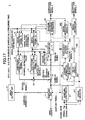
- FIG. 16 is a block diagram of a signal separator 3 according to the third embodiment of the invention.
- the signal separator 1 of the third embodiment includes a signal selector 201 for designating a selected signal, a third signal generator 202 for outputting a signal point based on the estimated signal, a channel estimation value storing unit (buffer) 204 for storing the past channel estimation values, a third coefficient-variable filter 203 using a value representing the level fluctuation and the phase rotation stored in the channel estimation value storing unit 204 as the filter coefficient, a delay circuit 205 for dallying the received signal, a subtractor 206, and a signal estimator 207, in addition to the components of the signal separator 1 of the first embodiment.
- a signal selector 201 for designating a selected signal
- a third signal generator 202 for outputting a signal point based on the estimated signal
- a channel estimation value storing unit (buffer) 204 for storing the past channel estimation values
- signal separator 3 makes use of the structure of signal separator 1 of the first embodiment, it may be applied to signal separator 2 of the second embodiment.
- the signal separator 3 estimates multiple signals, as in the first embodiment.
- the signal selector 201 selects a signal with a high reception quality based on, for example, the signal power level, the CNR, the SNR, or the bit error rate, among the multiple signals included in the received signal.
- signal 1 is selected as one having a high reception quality (or a high power level).
- the selection result is supplied to the maximum likelihood sequence estimator 22, and the estimation result of signal 1 is then supplied from the maximum likelihood sequence estimator 22 to the third signal generator 202 for the selected signal.
- the power levels of the multiple signals may be compared using the receiving power levels of the control signals transmitted from the multiple signals.
- the power levels may be measured using difference sequences of PN codes as the identification signals.
- the channel estimation value storing unit 204 stores the selection result, as well as the estimated channel value of the selected signal.
- the signal generator 202 outputs the signal point corresponding to the channel estimation result of the selected signal to the coefficient-variable filter 203. Since the maximum likelihood sequence estimator 22 implements maximum likelihood estimation for the signal sequence using the state transition diagram, the signal output operation delays by a few symbols. For this reason, the coefficient-variable filter 203 determines the filter coefficient using a past channel estimation value tracing back by a delay time generated at the maximum likelihood sequence estimator 22, and adds the level fluctuation, the phase rotation, and the delay component to the signal point supplied from the signal generator 202. In this manner, a replica of the past signal can be generated using the estimation result of the maximum likelihood sequence estimator 22.
- the sampled input signal (received signal) is delayed by the delay circuit 205 by a delay time generated at the maximum likelihood sequence estimator 22.
- the replica signal generated from the delayed received signal is subtracted from the delayed received signal at the subtractor 206.
- the remaining signal is obtained by removing the selected signal from the received signal.
- a signal estimated by the maximum likelihood sequence estimator 22 at low estimation error is used as a selected signal, and a replica of the selected signal is generated at high accuracy, while reducing the estimation error in the non-selected signal represented by the subtraction result.
- the arrangement of the third embodiment is advantageous in the circumstances where the estimation result of one signal includes a lot of errors, while the other estimated signals include less error, among the multiple signals. Even under such a situation, a high-quality signal (with a high power level) with less error is selected from the received signal, and the replica of the selected signal is subtracted from the received signal to extract the signal waveform of the low-power signal containing errors. Consequently, bit error rate can be reduced as a whole.
- FIG. 17 is a block diagram of a signal separator 4 according to the fourth embodiment of the invention.
- the signal selection is performed based on the symbol rates of the signals, and the other functions and structures are the same as those of the signal separator 3 of the third embodiment. Accordingly, explanation is made only of the different portion, that is, the operation of the signal selector.
- the same components as those in the third embodiment are denoted by the same reference numbers.
- the signal selector 211 selects a signal with a low symbol rate. Since a low-symbol-rate signal, which is likely to lead to a low estimation error at the maximum likelihood sequence estimator 22, is selected, the errors can be reduced as the entirety of the multiple signals.
- a replica of the selected signal with a low estimation error is generated, and the replica is subtracted from the received signal.
- the remaining signals are estimated using the subtraction result, and consequently, estimation error can be reduced as a whole.
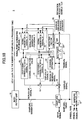
- FIG. 18 is a block diagram of a signal separator 5 according to the fifth embodiment of the invention.
- the signal separator 5 has a weighting factor controller 220, in addition to the components of signal separator 1 of the first embodiment.
- the weighting factor controller 220 of the fifth embodiment may be applied to any of signal separators 2, 3, and 4 of the second through fourth embodiments.
- the maximum likelihood sequence estimator 22 if a lot of replica signal points exist in the signal space, located close to each other, the maximum likelihood sequence estimator 22 is likely to produce signal estimation error. In contrast, if the number of replica signal points in the signal space is small, with sufficient separation from each other, then the maximum likelihood sequence estimator 22 can perform signal estimation at high accuracy.
- This arrangement can improve the signal estimation accuracy at the maximum likelihood sequence estimator 22.
- the channel estimator 20 supplies the channel estimation value to the weighting factor controller 220. If the signal point separation calculated from the estimated channel value is small, the weighting factor controller 220 adjusts the weighting factor to be smaller. If the signal point separation is large, the weighting factor is set greater. As an actual example of the weighting factor determination method, a weighing factor given to the minimum separation between the replica signal points is determined in advance, and that weighting factor is stored in the database in association with the minimum separation. The weighting factor controller 220 uses the database as a reference when determining a weighting factor corresponding to a signal point separation. This arrangement can achieve accurate separation of multiple signals.
- the weighting factor applied to the residual signal is made smaller to reduce the contribution to the signal estimation.
- the weighting factor applied to the residual signal is increased to enhance the contribution to the signal estimation. In this manner, the received signal sequence can be estimated accurately.
- the signal separator is assembled in a wireless receiver, it may be used independently.
Landscapes
- Engineering & Computer Science (AREA)
- Power Engineering (AREA)
- Computer Networks & Wireless Communication (AREA)
- Signal Processing (AREA)
- Cable Transmission Systems, Equalization Of Radio And Reduction Of Echo (AREA)
- Noise Elimination (AREA)
Claims (12)
- Signaltrenner (1), um Mehrfachsignale, die in einem empfangenen Signal enthalten sind, auf der Basis einer Kopie des empfangenen Signals voneinander zu trennen, Folgendes umfassend:eine Abtasteinheit (11), konfiguriert zum Abtasten des empfangenen Signals an vorgegebenen Abtast-Timings in jeder Einheitszeitperiode;eine Indexausgabeeinheit (13), die dazu konfiguriert ist, von der Abtasteinheit empfangene Abtastzählungen (n1) zu überwachen und ein Indexsignal auszugeben, das Indizes einschließt, die Gruppen von Abtastwerten des empfangenen Signals kennzeichnen, worin die Indexausgabeeinheit jeden der Indizes (n2) dadurch erhält, dass sie einen Rest der Division einer Abtastzählung am entsprechenden Abtast-Timing durch die Anzahl von Abtast-Timings in der Einheitszeitperiode so berechnet, dass die abgetasteten Signale in mehrfache Kategorien auf der Basis der Indizes (n2) gruppiert werden, sodass die abgetasteten Signale, die in derselben Kategorie gruppiert sind, gemäß dem Abtast-Timing ähnliche Signalcharakteristiken haben;ein Filter mit variablen Koeffizienten (16, 17), konfiguriert zum Erzeugen und Ausgeben der Kopie des empfangenen Signals für jede Gruppe von Abtastwerten, auf einem Kanalschätzwert und einem Signalpunktkandidaten basierend, wobei mindestens eins des Kanalschätzwerts und des Signalpunktkandidaten gemäß dem Indexsignal erzeugt wird;einen Subtrahierer (19), konfiguriert zum Subtrahieren der Kopie vom abgetasteten Signal und zum Ausgeben eines Subtraktionsergebnisses als einem Restsignal; undeinen Maximum Likelihood Sequenz-Schätzer (22), konfiguriert zum Schätzen einer Sequenz für jedes der Mehrfachsignale auf der Basis des Restsignals, wobei der Signalstatusübergang berücksichtigt wird, und zum Ausgeben des Schätzergebnisses an einem Signalausgabe-Timing, das durch das Indexsignal bestimmt wird.
- Signaltrenner nach Anspruch 1, außerdem umfassend:einen Kanalschätzer (20), konfiguriert zum Schätzen von Pegelfluktuation und Phasendrehung für jedes der Mehrfachsignale im empfangenen Signal, um den Kanalschätzwert herzustellen; undeinen Signalgenerator (14, 15), der für jedes der Mehrfachsignale bereitgestellt ist und dazu konfiguriert ist, den Signalpunktkandidaten der assoziierten Mehrfachsignale in einem Signalraum entsprechend einem Wert des Indexsignals auszugeben.
- Signaltrenner nach Anspruch 1, außerdem umfassend:einen Kanalschätzer (20), konfiguriert zum Schätzen von Pegelfluktuation und Phasendrehung für jedes der Mehrfachsignale im empfangenen Signal, um den Kanalschätzwert gemäß einem Wert des Indexsignals herzustellen; undeinen Signalgenerator (14, 15), der für jedes der Mehrfachsignale bereitgestellt ist und dazu konfiguriert ist, die Signalpunktkandidaten der assoziierten Mehrfachsignale in einem Signalraum auszugeben.
- Signaltrenner nach einem der Ansprüche 1 bis 3, außerdem umfassend:einen Signalselektor, konfiguriert zum Auswählen von einem der Mehrfachsignale;einen Speicher, konfiguriert zum Speichern des Kanalschätzwerts des ausgewählten Signals für eine vorgegebene Zeit;einen Signalgenerator, für das ausgewählte Signal bereitgestellt und dazu konfiguriert, den Signalpunkt auszugeben, der dem Schätzergebnis des ausgewählten Signals entspricht, das vom Maximum Likelihood Sequenz-Schätzer bereitgestellt wird;ein zweites Filter mit variablen Koeffizienten, konfiguriert zum Einstellen eines Filterkoeffizienten mit Bezug auf den gespeicherten Kanalschätzwert und zum Ausgeben einer Kopie des ausgewählten Signals unter Verwendung des Signalpunkts des ausgewählten Signals, der vom Signalgenerator bereitgestellt wird;eine Verzögerungseinheit, konfiguriert zum Verzögern des empfangenen Signals für die vorgegebene Zeit; undeinen zweiten Subtrahierer, konfiguriert zum Subtrahieren der Kopie des ausgewählten Signals vom verzögerten Signal.
- Signaltrenner nach Anspruch 4, worin der Signalselektor Signale mit einer Empfangsqualität auswählt, die höher ist als ein vorgegebenes Qualitätsniveau.
- Signaltrenner nach Anspruch 4, worin der Signalselektor Signale mit einer Symbolrate auswählt, die niedriger ist als ein vorgegebenes Niveau.
- Signaltrenner nach Anspruch 1, außerdem umfassend:einen Signalgenerator, konfiguriert zum Erzeugen einer Signalwellenform für jeden der Symbolsequenzkandidaten des empfangenen Signals und zum Abtasten der Signalwellenform am vorgegebenen Abtast-Timing, um den Signalpunktkandidaten für jedes der Mehrfachsignale im Signalraum auszugeben.
- Signaltrenner nach Anspruch 1, außerdem umfassend:einen Multiplizierer, konfiguriert zum Multiplizieren des Restsignals mit sich selbst und zum Weiterleiten des Multiplikationsergebnisses an den Maximum Likelihood Sequenz-Schätzer.
- Signaltrenner nach Anspruch 8, außerdem umfassend:eine Gewichtungsfaktorsteuerung, konfiguriert zum Einstellen eines Gewichtungsfaktors gemäß jedem Wert des Indexsignals und zum Anwenden des Gewichtungsfaktors auf das Multiplikationsergebnis, bevor das Multiplikationsergebnis in den Maximum Likelihood Sequenz-Schätzer eingegeben wird.
- Signaltrenner nach Anspruch 1, außerdem umfassend:eine Abtast-Timing-Steuerung (12), konfiguriert zum Bestimmen des vorgegebenen Abtast-Timing, um die Abtasteinheit zu veranlassen, das empfangene Signal gemäß den Symbolraten der Mehrfachsignale abzutasten und die abgetasteten Signale als Zeitreihe auszugeben.
- Signaltrenner nach Anspruch 1, außerdem umfassend:eine Abtast-Timing-Steuerung (12), konfiguriert zum Bestimmen des vorgegebenen Abtast-Timing, um die Abtasteinheit zu veranlassen, das empfangene Signal gemäß einem gemeinsamen Vielfachen von Symbolraten der Mehrfachsignale abzutasten.
- Signaltrenner nach Anspruch 1, worin das Filter mit variablen Koeffizienten (16, 17) eine Vielzahl von Eingangs-Abgriffen für das assoziierte Signal hat, das mit einer zeitgespreizten Verzögerungswelle ankommt, und die Kopie des assoziierten Signals einschließlich der Verzögerungswelle ausgibt.
Applications Claiming Priority (4)
| Application Number | Priority Date | Filing Date | Title |
|---|---|---|---|
| JP2004027279 | 2004-02-03 | ||
| JP2004027279 | 2004-02-03 | ||
| JP2004136663A JP4403010B2 (ja) | 2004-02-03 | 2004-04-30 | 信号分離装置 |
| JP2004136663 | 2004-04-30 |
Publications (2)
| Publication Number | Publication Date |
|---|---|
| EP1562303A1 EP1562303A1 (de) | 2005-08-10 |
| EP1562303B1 true EP1562303B1 (de) | 2015-08-12 |
Family
ID=34680679
Family Applications (1)
| Application Number | Title | Priority Date | Filing Date |
|---|---|---|---|
| EP05250559.1A Expired - Lifetime EP1562303B1 (de) | 2004-02-03 | 2005-02-02 | Signaltrenner |
Country Status (4)
| Country | Link |
|---|---|
| US (1) | US7409017B2 (de) |
| EP (1) | EP1562303B1 (de) |
| JP (1) | JP4403010B2 (de) |
| CN (1) | CN100375396C (de) |
Families Citing this family (17)
| Publication number | Priority date | Publication date | Assignee | Title |
|---|---|---|---|---|
| TWI294236B (en) * | 2005-06-16 | 2008-03-01 | Realtek Semiconductor Corp | Method and apparatus for correcting symbol timing |
| US7773733B2 (en) * | 2005-06-23 | 2010-08-10 | Agere Systems Inc. | Single-transformer digital isolation barrier |
| US8213489B2 (en) * | 2005-06-23 | 2012-07-03 | Agere Systems Inc. | Serial protocol for agile sample rate switching |
| US7587170B1 (en) * | 2005-10-14 | 2009-09-08 | Marvell Semiconductor, Inc. | Digital radio data system receiver methods and apparatus |
| CN101449502B (zh) * | 2006-05-19 | 2012-11-07 | 松下电器产业株式会社 | 无线通信设备和无线通信方法 |
| GB0724416D0 (en) * | 2007-12-14 | 2008-01-30 | Icera Inc | Generating channel estimates in a radio receiver |
| CN101471640B (zh) * | 2007-12-27 | 2011-08-17 | 中国科学院声学研究所 | 一种窄带滤波器组件 |
| JP5108794B2 (ja) * | 2009-01-07 | 2012-12-26 | 株式会社エヌ・ティ・ティ・ドコモ | 無線基地局装置及び無線通信方法 |
| US9338031B2 (en) * | 2009-08-17 | 2016-05-10 | Qualcomm Incorporated | Methods and apparatus for interference decrease/cancellation on downlink acquisition signals |
| US9270304B2 (en) * | 2012-11-07 | 2016-02-23 | Datum Systems, Inc. | Method and apparatus for nonlinear-channel identification and estimation of nonlinear-distorted signals |
| KR102301031B1 (ko) | 2014-12-31 | 2021-09-13 | 삼성전자주식회사 | 모바일 기기에서 신호를 처리하는 방법 및 장치 |
| US9590673B2 (en) * | 2015-01-20 | 2017-03-07 | Qualcomm Incorporated | Switched, simultaneous and cascaded interference cancellation |
| US10623986B2 (en) | 2015-10-22 | 2020-04-14 | Photonic Systems, Inc. | RF signal separation and suppression system and method |
| US10158432B2 (en) * | 2015-10-22 | 2018-12-18 | Photonic Systems, Inc. | RF signal separation and suppression system and method |
| CN108415012A (zh) * | 2018-02-06 | 2018-08-17 | 中国人民解放军战略支援部队信息工程大学 | 一种单通道跳频信号分选方法与装置 |
| DE102019209801A1 (de) * | 2019-07-03 | 2021-01-07 | Innovationszentrum für Telekommunikationstechnik GmbH IZT | Empfänger zum Empfangen eines Kombinationssignals mit Berücksichtigung einer Inter-Symbol-Interferenz und niedriger Komplexität, Verfahren zum Empfangen eines Kombinationssignals und Computerprogramm |
| JP7221191B2 (ja) * | 2019-10-23 | 2023-02-13 | 株式会社Kddi総合研究所 | 受信装置、受信方法及びコンピュータプログラム |
Family Cites Families (10)
| Publication number | Priority date | Publication date | Assignee | Title |
|---|---|---|---|---|
| EP0449327B1 (de) * | 1990-03-30 | 1998-07-15 | Nec Corporation | Störungsunempfindlicher Raumdiversityempfänger |
| US6028901A (en) * | 1994-05-19 | 2000-02-22 | Hughes Electronics Corporation | Receiver selection based on delay spread estimation |
| JP3424724B2 (ja) | 1996-12-18 | 2003-07-07 | 株式会社エヌ・ティ・ティ・ドコモ | 干渉キャンセラ |
| CN1127228C (zh) * | 1997-06-03 | 2003-11-05 | Ntt移动通信网株式会社 | 自适应阵列收发射机 |
| US6108517A (en) * | 1997-07-28 | 2000-08-22 | Ericsson Inc. | Methods and apparatus for joint demodulation of adjacent channel signals in digital communications systems |
| JPH11251959A (ja) | 1998-03-05 | 1999-09-17 | Fujitsu Ltd | 干渉キャンセラ装置及び無線通信装置 |
| US7218666B2 (en) * | 2000-12-29 | 2007-05-15 | Motorola, Inc. | Method and system for transmission and frequency domain equalization for wideband CDMA system |
| US6975672B2 (en) * | 2001-01-08 | 2005-12-13 | Ericsson Inc. | Apparatus and methods for intersymbol interference compensation in spread spectrum communications |
| US6977977B1 (en) * | 2001-02-20 | 2005-12-20 | Comsys Communication & Signal Processing Ltd. | Compensation of I/Q gain mismatch in a communications receiver |
| EP1554798B1 (de) * | 2002-07-24 | 2018-05-30 | Collision Communications, Inc. | Cokanal-störungsempfänger |
-
2004
- 2004-04-30 JP JP2004136663A patent/JP4403010B2/ja not_active Expired - Fee Related
-
2005
- 2005-02-01 US US11/046,841 patent/US7409017B2/en not_active Expired - Fee Related
- 2005-02-02 EP EP05250559.1A patent/EP1562303B1/de not_active Expired - Lifetime
- 2005-02-03 CN CNB2005100016354A patent/CN100375396C/zh not_active Expired - Fee Related
Also Published As
| Publication number | Publication date |
|---|---|
| CN1652472A (zh) | 2005-08-10 |
| CN100375396C (zh) | 2008-03-12 |
| US20050195922A1 (en) | 2005-09-08 |
| US7409017B2 (en) | 2008-08-05 |
| JP4403010B2 (ja) | 2010-01-20 |
| JP2005253032A (ja) | 2005-09-15 |
| EP1562303A1 (de) | 2005-08-10 |
Similar Documents
| Publication | Publication Date | Title |
|---|---|---|
| EP1562303B1 (de) | Signaltrenner | |
| US6944245B2 (en) | Multi-pass interference reduction in a GSM communication system | |
| KR100982929B1 (ko) | 무선 통신 시스템용 적응형 파일럿 필터의 선택 | |
| CN100385817C (zh) | 滑动相关器 | |
| JP5346074B2 (ja) | 共分散ルート処理を伴う逐次干渉除去のための方法及び装置 | |
| EP1224780B1 (de) | Basisbandprozessor mit vorausschau der parameterschätzungsfähigkeiten | |
| US6580772B2 (en) | Method of forming channel estimate, and receiver | |
| EP1552641B1 (de) | Optimales interpolatorverfahren und vorrichtung zur digitalen timing-einstellung | |
| JP3443113B2 (ja) | 無線受信装置及び無線受信方法 | |
| US7167529B2 (en) | Method and device for radio signal reception | |
| US7599426B2 (en) | Use of adaptive filters in multiple access wireless systems employing predictable signals | |
| US7636407B2 (en) | Signal detector used in wireless communication system | |
| EP2087606B1 (de) | Verfahren und vorrichtung für effiziente signalinterpolierung | |
| US7508870B2 (en) | Method and apparatus for channel estimation in radio systems by MMSE-based recursive filtering | |
| US20020181554A1 (en) | Adaptive rake receiving apparatus constrained with at least one constraint for use in mobile communication system and method therefor | |
| US20040097204A1 (en) | Multi-subscriber detection using a rake receiver structure | |
| CN100556011C (zh) | 自适应滤波器 | |
| US8743910B2 (en) | Method and apparatus for selecting a channel filter for a communication system | |
| JP5001427B2 (ja) | ルックアップテーブルによる共分散の効率的な算出 | |
| US20050036539A1 (en) | Adaptive channel estimation by means of variation of the integration length during the despreading of spread-coded training symbol sequences | |
| Łopatka | Recognition of narrowband radio signals using autoregressive models and pattern comparison approach | |
| Ye | Zero-based blind channel estimation and equalization |
Legal Events
| Date | Code | Title | Description |
|---|---|---|---|
| PUAI | Public reference made under article 153(3) epc to a published international application that has entered the european phase |
Free format text: ORIGINAL CODE: 0009012 |
|
| 17P | Request for examination filed |
Effective date: 20050222 |
|
| AK | Designated contracting states |
Kind code of ref document: A1 Designated state(s): AT BE BG CH CY CZ DE DK EE ES FI FR GB GR HU IE IS IT LI LT LU MC NL PL PT RO SE SI SK TR |
|
| AX | Request for extension of the european patent |
Extension state: AL BA HR LV MK YU |
|
| AKX | Designation fees paid |
Designated state(s): DE GB |
|
| 17Q | First examination report despatched |
Effective date: 20070511 |
|
| GRAP | Despatch of communication of intention to grant a patent |
Free format text: ORIGINAL CODE: EPIDOSNIGR1 |
|
| INTG | Intention to grant announced |
Effective date: 20150226 |
|
| GRAS | Grant fee paid |
Free format text: ORIGINAL CODE: EPIDOSNIGR3 |
|
| GRAA | (expected) grant |
Free format text: ORIGINAL CODE: 0009210 |
|
| RAP1 | Party data changed (applicant data changed or rights of an application transferred) |
Owner name: NTT DOCOMO, INC. |
|
| AK | Designated contracting states |
Kind code of ref document: B1 Designated state(s): DE GB |
|
| REG | Reference to a national code |
Ref country code: GB Ref legal event code: FG4D |
|
| REG | Reference to a national code |
Ref country code: DE Ref legal event code: R096 Ref document number: 602005047198 Country of ref document: DE |
|
| REG | Reference to a national code |
Ref country code: DE Ref legal event code: R097 Ref document number: 602005047198 Country of ref document: DE |
|
| PLBE | No opposition filed within time limit |
Free format text: ORIGINAL CODE: 0009261 |
|
| STAA | Information on the status of an ep patent application or granted ep patent |
Free format text: STATUS: NO OPPOSITION FILED WITHIN TIME LIMIT |
|
| 26N | No opposition filed |
Effective date: 20160513 |
|
| PGFP | Annual fee paid to national office [announced via postgrant information from national office to epo] |
Ref country code: DE Payment date: 20190122 Year of fee payment: 15 Ref country code: GB Payment date: 20190130 Year of fee payment: 15 |
|
| REG | Reference to a national code |
Ref country code: DE Ref legal event code: R119 Ref document number: 602005047198 Country of ref document: DE |
|
| GBPC | Gb: european patent ceased through non-payment of renewal fee |
Effective date: 20200202 |
|
| PG25 | Lapsed in a contracting state [announced via postgrant information from national office to epo] |
Ref country code: GB Free format text: LAPSE BECAUSE OF NON-PAYMENT OF DUE FEES Effective date: 20200202 Ref country code: DE Free format text: LAPSE BECAUSE OF NON-PAYMENT OF DUE FEES Effective date: 20200901 |