EP1562272A2 - Anordnung zur Zustandskontrolle und Protokollierung von Überspannungsschutz-Geräten, insbesondere bei deren Einsatz in Niederspannungsnetzen oder der Informationstechnik - Google Patents
Anordnung zur Zustandskontrolle und Protokollierung von Überspannungsschutz-Geräten, insbesondere bei deren Einsatz in Niederspannungsnetzen oder der Informationstechnik Download PDFInfo
- Publication number
- EP1562272A2 EP1562272A2 EP04029191A EP04029191A EP1562272A2 EP 1562272 A2 EP1562272 A2 EP 1562272A2 EP 04029191 A EP04029191 A EP 04029191A EP 04029191 A EP04029191 A EP 04029191A EP 1562272 A2 EP1562272 A2 EP 1562272A2
- Authority
- EP
- European Patent Office
- Prior art keywords
- transponder
- overvoltage protection
- arrangement according
- protection device
- circuit board
- Prior art date
- Legal status (The legal status is an assumption and is not a legal conclusion. Google has not performed a legal analysis and makes no representation as to the accuracy of the status listed.)
- Granted
Links
Images


Classifications
-
- H—ELECTRICITY
- H01—ELECTRIC ELEMENTS
- H01T—SPARK GAPS; OVERVOLTAGE ARRESTERS USING SPARK GAPS; SPARKING PLUGS; CORONA DEVICES; GENERATING IONS TO BE INTRODUCED INTO NON-ENCLOSED GASES
- H01T1/00—Details of spark gaps
- H01T1/12—Means structurally associated with spark gap for recording operation thereof
-
- H—ELECTRICITY
- H02—GENERATION; CONVERSION OR DISTRIBUTION OF ELECTRIC POWER
- H02H—EMERGENCY PROTECTIVE CIRCUIT ARRANGEMENTS
- H02H3/00—Emergency protective circuit arrangements for automatic disconnection directly responsive to an undesired change from normal electric working condition with or without subsequent reconnection ; integrated protection
- H02H3/02—Details
- H02H3/04—Details with warning or supervision in addition to disconnection, e.g. for indicating that protective apparatus has functioned
- H02H3/048—Checking overvoltage diverters
Definitions
- the invention relates to an arrangement for condition control and logging of overvoltage protection devices, especially when used in Low-voltage networks or information technology, comprising at least one, with the overvoltage protection device in a housing structurally combined Error detection unit, according to the preamble of patent claim 1.
- a major disadvantage of the described prior art is that the circuit of the signaler circuit in the surge protection device must be introduced. This in turn requires measures for Separation of the circuits of the overvoltage protection and the signal generator circuit. However, such a measure requires a lot of space in the housing of the surge protection device and leads to a high Effort in the installation and wiring of the signaling device circuit.
- the z. B. may be a temperature-dependent switching device, via an RFID transponder read out and queried.
- the RFID transponder is located in the same housing as the actual overvoltage protection elements, which form the overvoltage protection device.
- RFID Radio Frequency Identification
- an RFID system consists of the components transponder, which is attached to the objects to be identified, and a detection or reading device, which is available depending on the design and technology used as a read or write / read unit.
- the transponder which represents the actual data carrier of the RFID system, usually consists of a coupling element and a microchip. Passive transponders do not have their own power supply. All power to drive a passive transponder is taken from the reader's electrical or magnetic field.
- One-bit transponders are able to display two system states, on the one hand the state transponder in the response area or on the other hand the state no transponder in the response region.
- LC resonant circuits which are adjusted to a defined resonant frequency.
- z. B the natural frequency of the alternating field of the transponder resonant circuit of the resonant frequency of the Sendeschwing Vietnamesees, this creates a resonant oscillation, which extracts the magnetic alternating field energy.
- the initial oscillation process can be detected as a voltage or current change.
- an RFID transponder as a one-bit transponder is in the event of a fault of the overvoltage protection device on the Error detection unit changes the resonance frequency of the transponder or the resonant circuit of the transponder is interrupted.
- the RFID transponder as a passive transponder with inductive coupled power supply and existing identification circuit with memory function, which manufacture and application-specific Information as well as test and characteristic data contains, in the case of error of the Overvoltage protection device causes the error detection unit, the Short circuit or interrupt the transponder antenna circuit.
- the Short circuit or interrupt the transponder antenna circuit alternative can be switched on or off by antenna coil windings or Resonance circuit capacitances the resonant circuit frequency can be changed specifically.
- the error detection unit can be at least one temperature-dependent Switching device, in particular comprise a thermal fuse, which the respective overvoltage protection element of the overvoltage protection device, thermally in contact, is assigned.
- the identification circuit the transponder a device for protection against such Fields on, so the impact of ordinary surge currents on the Monitoring function module can be reduced.
- a protection circuit can be used as a voltage limiting module or as a blocking filter be executed.
- the RFID transponder arranged on a circuit board and it becomes the antenna of the transponder as a loop antenna along the outer edge regions of the circuit board executed.
- the RFID transponder circuit board adjacent is a support for receiving the overvoltage protection elements, for. B. in shape located by gas discharge arresters.
- the overvoltage protection elements on the carrier are in thermal contact with the thermal switching device (s) on the transponder circuit board.
- the transponder circuit board fulfills an insulation and shielding function with respect to the carrier with the overvoltage protection elements.
- the transponder circuit board and the carrier for receiving the overvoltage protection elements in parallel side by side in the housing of the surge protection device as interchangeable, separate functional modules are located.
- the carrier for receiving the Surge protection elements can also be made up as a printed circuit board a copper-clad material.
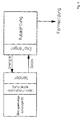
- the state control device configured as described above and logging of overvoltage protection devices is over Handheld readers queried. If necessary, in the transponder memory chip stored data is read and depending on the state control result is a Replacement of the respective surge protection device made.
- the Reader error messages generated optically and / or acoustically and remote query data about the condition of the respective overvoltage protection devices ready.
- the RFID transponder as inductively coupled Transponder with an additional sensor for detecting physical Sizes are designed for the state of the or the surge protection elements are relevant in the overvoltage protection device.
- the sensor as a temperature sensor for detecting the temperature and thus the load of the or overvoltage protection elements designed.
- the inventively proposed interruption or shorting the antenna of the transponder can turn on / off by simple means the identification circuit.
- detuning the antenna circuit by turning on or off of Windings of a loop antenna.
- This change in the resonant frequency is recognizable by the reader, so that a change of state of the to be monitored device can be concluded.
- the temperature-dependent switching device detected while the temperature of the monitored elements of the surge protective device. Due to the relationship between the energy input and the heating of the respective component can exceed the maximum permissible power loss a safe triggering of the temperature-dependent Switching done.
- the transponder assembly 6 is shown in FIG. 2 on a Printed circuit board 1 realized that an identification circuit 2, an antenna. 3 and temperature-dependent switching devices 4 and a circuit with Protection circuit 5 receives.
- the antenna 3 is designed according to the embodiment as a loop antenna. The contacting of the antenna 3 to the identification circuit 2 via at least one temperature-dependent switching device 4 and associated Interconnects.
- the special protection circuit 5 to the Terminals of the identification circuit 2 is provided (see also Fig. 5).
- the connection between identification circuit 2 and the Frame antenna 3 is interrupted, so that the transponder is no longer inductive can be stimulated. This no longer possible suggestion then corresponds a fault condition of the surge protection device, allowing an exchange is to be made.
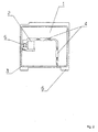
- Fig. 3 makes it clear that the circuit board 1 of the transponder assembly 6 in a housing part 7 is received, for which, for example, in the housing part. 7 groove-shaped guide receptacles are provided.
- overvoltage protection 9 z. B. gas discharge tube
- a support 8 which also be a circuit board can.
- the arrangement of the temperature-dependent switching devices 4, z. B. from Thermal fuses, takes place in a corresponding position relative to the monitoring components 9, in such a way that thermal energy of the Transfer components 9 as unhindered as possible to the respective thermal fuse can be.
- the circuit board 1 the transponder assembly 6 in the region of the position of the switching device 4 a Recess has, as Fig. 4 makes clear. This recess allows improved, intimate contact of the switching device 4 with the respective component 9 to be monitored.
- the circuit board 1 is according to the embodiment of FIG. 3 in substantially parallel to the carrier 8, which the overvoltage protection elements receives.
- An upper housing part 7.1 encloses the arrangement Transponder assembly and the actual overvoltage protection device, formed by the carrier 8 with the components provided there or Elements 9.
- the circuit board 1 additionally fulfills the function an electrical insulation and shielding, in particular with a view to the Properties of the identification circuit 2.
- an overvoltage protection device mounted transponder in the reading area of the reader is checked. This review is both in the mounted as well as disassembled possible.
- Over a Query routine that starts with the reader starts the investigation of the transponder state. If no transponder is detected, takes place an error message related to the overvoltage protection device. Will, however a transponder is recognized, the data stored in the transponder record transferred, processed in the reader and logged. Beyond that the important parameters for the documentation, eg. As test data displayed and stored for further processing.
- a fixed reader can be used to monitor several Surge protection devices are used. In particular, come here Readers are used, which have a greater reading range. Alone Reading range located transponder are continuously queried. Becomes If a transponder detects that it is no longer responding, an error message appears generated. About this error message will be the faulty overvoltage protection device identified and the user this information via a local Display or an error message.
- the transponder Due to the possibility of the transponder additionally in a housing of a Integrating overvoltage protection device is a possible upgrade given.
- the overvoltage protection devices are manufactured and assembled in the identification circuit of the respective transponder a record is saved.
- This record contains information like type, date of manufacture, test and / or characteristic values, which at a later Error detection or for documentation purposes, but also to gain insight used in the field of technical development can.
- the Protection circuit should here have the lowest possible capacity and the Transmission signal or not influence only to a small extent.
Abstract
Description
Den vorstehend beschriebenen Anordnungen ist gemeinsam, dass grundsätzlich eine Signalgeberschaltung notwendig ist, um einen erkannten Fehler mit Hilfe von optischen oder akustischen Signalen anzuzeigen.
Überspannungsschutz-Geräte, die keine Meldevorrichtung bezüglich ihres aktuellen Funktionsstatus besitzen, müssen demontiert werden und sind diskret mit einem Messgerät zu untersuchen.
Zur Dokumentation der Revision in Anlagen mit hohen Sicherheitsanforderungen, z. B. in Kraftwerken oder im Bereich der Petrochemie, ist darüber hinaus eine Protokollierung der Überprüfung mit Darstellung der einzelnen Überprüfungsschritte und -ergebnisse erforderlich.
Auch ist diejenige Energie, die zur Überlastung eines Überspannungsschutz-Geräts führen kann, in der Informationstechnik wesentlich geringer als in Niederspannungsnetzen.
Der Transponder, der den eigentlichen Datenträger des RFID-Systems darstellt, besteht üblicherweise aus einem Koppelelement sowie einem Mikrochip. Passive Transponder beinhalten keine eigene Energieversorgung. Die gesamte Energie zum Betrieb eines passiven Transponders wird dem elektrischen oder magnetischen Feld des Lesegeräts entnommen.
Ein-Bit-Transponder sind in der Lage, zwei Systemzustände darzustellen, und zwar einerseits den Zustand Transponder im Ansprechbereich oder andererseits den Zustand kein Transponder im Ansprechbereich. Bei weitverbreiteten Radiofrequenz-Verfahren zum Auslesen von RFID-Transpondern wird mit sogenannten L-C-Schwingkreisen gearbeitet, welche auf eine definierte Resonanzfrequenz abgeglichen sind. Entspricht z. B. die Eigenfrequenz des Wechselfeldes des Transponder-Schwingkreises der Resonanzfrequenz des Sendeschwingkreises, so entsteht eine Resonanzschwingung, die dem magnetischen Wechselfeld Energie entzieht. Der hier entstehende Anschwingvorgang kann als Spannungs- oder Stromänderung erfasst werden.
Die Transponder-Leiterplatte erfüllt gleichzeitig eine Isolations- und Schirmungsfunktion gegenüber dem Träger mit den Überspannungsschutz-Elementen.
- Fig. 1
- eine Prinzipdarstellung des berührungslosen Auslesens von Funktionseigenschaften eines Überspannungsschutz-Geräts;
- Fig. 2
- eine Seitenansicht einer realisierten Transponder-Baugruppe auf einer Leiterplatte mit Thermosicherungen;
- Fig. 3
- eine Zusammenstellungszeichnung eines Überspannungsschutz-Geräts mit den Funktionsbaugruppen Überspannungsschutz und Überwachung;
- Fig. 4
- eine Querschnittsdarstellung durch ein montiertes Überspannungsschutz-Gerät gemäß Fig. 3 mit erkennbarer thermischer Lagezuordnung zwischen den Überspannungsschutz-Elementen einerseits und den Thermosicherungen als Schaltelement andererseits und
- Fig. 5
- eine beispielhafte Transponder-Schutzschaltung.
Claims (16)
- Anordnung zur Zustandskontolle und Protokollierung von Überspannungsschutz-Geräten, insbesondere bei deren Einsatz in Niederspannungsnetzen oder der Informationstechnik, umfassend mindestens eine, mit dem Überspannungsschutz-Gerät in einem Gehäuse baulich vereinte Fehlererkennungseinheit,
dadurch gekennzeichnet, dass
die Fehlererkennungseinheit über einen im Gehäuse befindlichen RFID-Transponder ausles- und abfragbar ist. - Anordnung nach Anspruch 1,
dadurch gekennzeichnet, dass
der RFID-Transponder als Ein-Bit-Transponder ausgeführt ist, um den Zustand "Transponder im elektromagnetischen Lesefeld ermittelbar oder nicht" zu erkennen, wobei im Fehlerfall des Überspannungsschutz-Geräts die Fehlererkennungseinheit die Resonanzfrequenz des Transponders verändert oder den Schwingkreis des Transponders unterbricht. - Anordnung nach Anspruch 1,
dadurch gekennzeichnet, dass
der RFID-Transponder als passiver Transponder mit induktiv gekoppelter Spannungsversorgung ausgeführt ist und eine Identifikationsschaltung mit Speicherfunktion aufweist, welche herstellungs- und anwendungsspezifische Informationen sowie Prüf- und Kenndaten enthält, wobei im Fehlerfall des Überspannungsschutz-Geräts die Fehlererkennungseinheit den Transponder-Antennenkreis kurzschließt oder unterbricht oder durch Zu- oder Abschalten von Antennenspulenwindungen oder Schwingkreiskapazitäten den Schwingkreis gezielt verstimmt. - Anordnung nach Anspruch 2 oder 3,
dadurch gekennzeichnet, dass
die Fehlererkennungseinheit mindestens eine temperaturabhängige Schalteinrichtung, insbesondere eine Thermosicherung umfasst, welche dem jeweiligen Überspannungsschutz-Element des Überspannungsschutz-Geräts, thermisch in Kontakt stehend, zugeordnet ist. - Anordnung nach Anspruch 1 oder 3,
dadurch gekennzeichnet, dass
die Identifikationsschaltung des Transponders mit einer Einrichtung zum Schutz gegen starke elektromagnetische Felder aufgrund üblicher Stoßströme bei Überspannungsschutz-Geräten in Verbindung steht. - Anordnung nach Anspruch 4,
dadurch gekennzeichnet, dass
für das Erkennen eines Fehlerzustands auf die Erwärmung der Überspannungsschutz-Elemente bei maximal zulässiger Verlustleistung abgestellt wird. - Anordnung nach einem der vorangegangenen Ansprüche,
dadurch gekennzeichnet, dass
der RFID-Transponder auf einer Leiterplatte angeordnet und die Antenne des Transponders als Rahmenantenne entlang der Außenrandbereiche der Leiterplatte ausgeführt ist. - Anordnung nach Anspruch 7,
dadurch gekennzeichnet, dass
zwischen den Antennenspulen-Anschlussenden oder zwischen einem Antennenspulen-Anschlussende und dem zugehörigen Eingang der Identifikationsschaltung die Fehlererkennungseinheit auf der Leiterplatte in Form mindestens einer temperaturabhängigen Schalteinrichtung angeschlossen ist. - Anordnung nach Anspruch 7 und 8,
dadurch gekennzeichnet, dass
der RFID-Transponder-Leiterplatte benachbart ein Träger zur Aufnahme der Überspannungsschutz-Elemente befindlich ist. - Anordnung nach Anspruch 8 und 9,
dadurch gekennzeichnet, dass
die Überspannungsschutz-Elemente auf dem Träger in thermischem Kontakt zu der oder den thermischen Schalteinrichtungen auf der Transponder-Leiterplatte stehen. - Anordnung nach Anspruch 10,
dadurch gekennzeichnet, dass
die Transponder-Leiterplatte eine Isolation und/oder Schirmung gegenüber dem Träger mit den Überspannungsschutz-Elementen aufweist. - Anordnung nach Anspruch 7 bis 11,
dadurch gekennzeichnet, dass
die Transponder-Leiterplatte und der Träger zur Aufnahme der Überspannungsschutz-Elemente parallel nebeneinander im Gehäuse des Überspannungsschutz-Geräts als austauschbare, getrennte Funktionsbaugruppen befindlich sind. - Anordnung nach mindestens einem der vorangegangenen Ansprüche,
dadurch gekennzeichnet, dass
über ein Handlesegerät die Funktion des RFID-Transponders abgefragt, gegebenenfalls im Transponderspeicherchip abgelegte Daten ausgelesen und je nach Zustandskontrollergebnis ein Austausch des jeweiligen Überspannungsschutz-Geräts erfolgt. - Anordnung nach mindestens einem der Ansprüche 1 bis 12,
dadurch gekennzeichnet, dass
fest in der jeweilige Überspannungsschutz-Geräte enthaltenden Anlage ein oder mehrere Lesegeräte zur zyklischen Überwachung vorgesehen sind, wobei das Lesegerät Fehlermeldungen optisch und/oder akustisch erzeugt und Fernabfragedaten über den Zustand der jeweiligen Überspannungsschutz-Geräte bereit stellt. - Anordnung nach Anspruch 1,
dadurch gekennzeichnet, dass
der RFID-Transponder als induktiv gekoppelter Transponder mit zusätzlichem Sensor zur Erfassung physikalischer Größen, die für den Zustand des oder der Überspannungsschutz-Elemente im Überspannungsschutz-Gerät relevant sind, ausgeführt ist. - Anordnung nach Anspruch 15,
dadurch gekennzeichnet, dass
der Transponder einen Temperatursensor zur Erfassung der Temperatur und damit der Belastung des oder der Überspannungsschutz-Elemente umfasst.
Applications Claiming Priority (4)
| Application Number | Priority Date | Filing Date | Title |
|---|---|---|---|
| DE102004002022 | 2004-01-14 | ||
| DE102004002022 | 2004-01-14 | ||
| DE102004006987A DE102004006987B3 (de) | 2004-01-14 | 2004-02-12 | Anordnung zur Zustandskontrolle und Protokollierung von Überspannungsschutz-Geräten, insbesondere bei deren Einsatz in Niederspannungsnetzen oder der Informationstechnik |
| DE102004006987 | 2004-02-12 |
Publications (3)
| Publication Number | Publication Date |
|---|---|
| EP1562272A2 true EP1562272A2 (de) | 2005-08-10 |
| EP1562272A3 EP1562272A3 (de) | 2009-03-04 |
| EP1562272B1 EP1562272B1 (de) | 2016-09-07 |
Family
ID=34680164
Family Applications (1)
| Application Number | Title | Priority Date | Filing Date |
|---|---|---|---|
| EP04029191.6A Not-in-force EP1562272B1 (de) | 2004-01-14 | 2004-12-09 | Anordnung zur Zustandskontrolle und Protokollierung von Überspannungsschutz-Geräten, insbesondere bei deren Einsatz in Niederspannungsnetzen oder der Informationstechnik |
Country Status (1)
| Country | Link |
|---|---|
| EP (1) | EP1562272B1 (de) |
Cited By (8)
| Publication number | Priority date | Publication date | Assignee | Title |
|---|---|---|---|---|
| WO2010079132A3 (de) * | 2009-01-12 | 2010-10-07 | Phoenix Contact Gmbh & Co.Kg | Überspannungsschutzelement |
| EP2286426A1 (de) * | 2008-05-09 | 2011-02-23 | Weidmüller Interface GmbH & Co. KG | Einrichtung und verfahren zur überwachung einer schutzvorrichtung |
| WO2014055042A1 (en) * | 2012-10-04 | 2014-04-10 | Strip's D.O.O. | Wireless and batteryless module for detecting operating mode of electric devices |
| WO2015000705A1 (en) * | 2013-07-02 | 2015-01-08 | Koninklijke Philips N.V. | Problem monitoring in cable system with fuses |
| WO2015001455A1 (en) * | 2013-07-02 | 2015-01-08 | Koninklijke Philips N.V. | Cable system problem detection via characteristic frequency |
| WO2015050506A1 (en) * | 2013-10-02 | 2015-04-09 | Strip's D.O.O. | Wireless and batteryless module for detecting operating mode of electric devices |
| CN105914726A (zh) * | 2015-02-23 | 2016-08-31 | 菲尼克斯电气公司 | 安装在印刷电路板上的过电压保护器装置 |
| CN106841888A (zh) * | 2016-10-17 | 2017-06-13 | 垂德尔塔麦登沙有限公司 | 电涌抑制器监控装置和包括监控装置的监控系统 |
Citations (5)
| Publication number | Priority date | Publication date | Assignee | Title |
|---|---|---|---|---|
| EP0350477A2 (de) * | 1988-07-06 | 1990-01-10 | Felten & Guilleaume Fabrik elektrischer Apparate Aktiengesellschaft | Abtrennvorrichtung für Überspannungsableiter |
| EP0915345A2 (de) * | 1997-11-08 | 1999-05-12 | Asea Brown Boveri AG | Elektrischer Apparat, insbesondere Ueberspannungsableiter, mit einer Vorrichtung zur Anzeige eines Fehlerstroms |
| WO1999035691A1 (en) * | 1998-01-09 | 1999-07-15 | Microchip Technology Incorporated | An integrated circuit (ic) package including accompanying ic chip and coil and a method of production therefor |
| EP1022837A2 (de) * | 1999-01-22 | 2000-07-26 | Zymax International Limited | Überspannungsschutz |
| EP1179827A1 (de) * | 2000-08-08 | 2002-02-13 | Schneider Electric Industries SA | Elektrisches Gerät mit Kontrollvorrichtung, Stütz- und Überwachungseinrichtung für ein solches Gerät, und elektrische Installation, die sie enthält |
-
2004
- 2004-12-09 EP EP04029191.6A patent/EP1562272B1/de not_active Not-in-force
Patent Citations (5)
| Publication number | Priority date | Publication date | Assignee | Title |
|---|---|---|---|---|
| EP0350477A2 (de) * | 1988-07-06 | 1990-01-10 | Felten & Guilleaume Fabrik elektrischer Apparate Aktiengesellschaft | Abtrennvorrichtung für Überspannungsableiter |
| EP0915345A2 (de) * | 1997-11-08 | 1999-05-12 | Asea Brown Boveri AG | Elektrischer Apparat, insbesondere Ueberspannungsableiter, mit einer Vorrichtung zur Anzeige eines Fehlerstroms |
| WO1999035691A1 (en) * | 1998-01-09 | 1999-07-15 | Microchip Technology Incorporated | An integrated circuit (ic) package including accompanying ic chip and coil and a method of production therefor |
| EP1022837A2 (de) * | 1999-01-22 | 2000-07-26 | Zymax International Limited | Überspannungsschutz |
| EP1179827A1 (de) * | 2000-08-08 | 2002-02-13 | Schneider Electric Industries SA | Elektrisches Gerät mit Kontrollvorrichtung, Stütz- und Überwachungseinrichtung für ein solches Gerät, und elektrische Installation, die sie enthält |
Cited By (12)
| Publication number | Priority date | Publication date | Assignee | Title |
|---|---|---|---|---|
| EP2286426A1 (de) * | 2008-05-09 | 2011-02-23 | Weidmüller Interface GmbH & Co. KG | Einrichtung und verfahren zur überwachung einer schutzvorrichtung |
| WO2010079132A3 (de) * | 2009-01-12 | 2010-10-07 | Phoenix Contact Gmbh & Co.Kg | Überspannungsschutzelement |
| EP2675031A1 (de) * | 2009-01-12 | 2013-12-18 | PHOENIX CONTACT GmbH & Co. KG | Überspannungsschutzelement |
| US8634176B2 (en) | 2009-01-12 | 2014-01-21 | Phoenix Contact GmbH Co. KG | Overvoltage protector |
| US9118175B2 (en) | 2009-01-12 | 2015-08-25 | Phoenix Contact Gmbh & Co. Kg | Overvoltage protector |
| WO2014055042A1 (en) * | 2012-10-04 | 2014-04-10 | Strip's D.O.O. | Wireless and batteryless module for detecting operating mode of electric devices |
| WO2015000705A1 (en) * | 2013-07-02 | 2015-01-08 | Koninklijke Philips N.V. | Problem monitoring in cable system with fuses |
| WO2015001455A1 (en) * | 2013-07-02 | 2015-01-08 | Koninklijke Philips N.V. | Cable system problem detection via characteristic frequency |
| WO2015050506A1 (en) * | 2013-10-02 | 2015-04-09 | Strip's D.O.O. | Wireless and batteryless module for detecting operating mode of electric devices |
| CN105914726A (zh) * | 2015-02-23 | 2016-08-31 | 菲尼克斯电气公司 | 安装在印刷电路板上的过电压保护器装置 |
| CN105914726B (zh) * | 2015-02-23 | 2019-01-15 | 菲尼克斯电气公司 | 安装在印刷电路板上的过电压保护器装置 |
| CN106841888A (zh) * | 2016-10-17 | 2017-06-13 | 垂德尔塔麦登沙有限公司 | 电涌抑制器监控装置和包括监控装置的监控系统 |
Also Published As
| Publication number | Publication date |
|---|---|
| EP1562272B1 (de) | 2016-09-07 |
| EP1562272A3 (de) | 2009-03-04 |
Similar Documents
| Publication | Publication Date | Title |
|---|---|---|
| DE102004006987B3 (de) | Anordnung zur Zustandskontrolle und Protokollierung von Überspannungsschutz-Geräten, insbesondere bei deren Einsatz in Niederspannungsnetzen oder der Informationstechnik | |
| EP1737091B1 (de) | Überspannungsableiter, umfassend ein schienenmontierbares Basisteil mit elektrischer Anschlussklemmen sowie ein auswechselbares Einsteckteil | |
| EP2724436B1 (de) | Zustandskontroll- oder diagnosesystem | |
| DE102012004716B4 (de) | Schaltungsanordnung zur Zustandskontrolle und Protokollierung von Überspannungsschutzgeräten oder Überspannungsschutzanlagen | |
| EP2675031B1 (de) | Überspannungsschutzelement | |
| DE102008008072A1 (de) | Sensor | |
| EP3469224A1 (de) | Gleitlager, kunststoffgleitelement, system und verfahren zur verschleisserkennung | |
| DE10138261A1 (de) | Sensorvorrichtung zur Überwachung der für eine kraftschlüssige Verbindung zwischen Werkstücken vorzusehenden entscheidenden Kraft | |
| EP1094418A2 (de) | Chipkarte | |
| DE102009005100B4 (de) | Transpondervorrichtung zur Speicherung von Daten, Transponderetikett und Verfahren zum Feststellen eines Zustands einer Transpondervorrichtung | |
| EP1562272B1 (de) | Anordnung zur Zustandskontrolle und Protokollierung von Überspannungsschutz-Geräten, insbesondere bei deren Einsatz in Niederspannungsnetzen oder der Informationstechnik | |
| WO2007019993A1 (de) | Sensorvorrichtung mit schwingkreisortungssystem und übertragung kodierter informationen | |
| WO2008092469A1 (de) | Schmelzsicherung, auswertevorrichtung und system mit mindestens einer schmelzsicherung und mindestens einer auswertevorrichtung | |
| EP1914694A1 (de) | Selbstbedienungsgerät mit Überwachungsvorrichtung | |
| DE212009000026U1 (de) | Verbindungssensor zur Identifikation einer Anschlussstelle in einer Schalttafel | |
| DE102006037364A1 (de) | Sensorvorrichtung | |
| EP0513952B1 (de) | Schaltung zur Störungserfassung für eine elektronische Baugruppe | |
| EP0596584B1 (de) | Einrichtung zur Störungserfassung | |
| DE102008014521A1 (de) | System zur Fernerkennung von Strukturschäden technischer Objekte | |
| DE102020000494A1 (de) | Mechanisch aktivierbarer RFID Transponder und Montagebauteil mit einem mechanisch aktivierbaren RFID Transponder | |
| DE102017110990B4 (de) | Kondensator | |
| EP1687751B2 (de) | Chipkartenlesevorrichtung und eine chipkarte zum betreiben an einer derartigen lesevorrichtung | |
| DE102015000443B4 (de) | Anordnung zur Erkennung der Anwesenheit von Werkzeugen/Instrumenten in einer zugehörigen Sammelablage | |
| DE202019005381U1 (de) | Elektrisches Gerät mit zumindest einer elektrischen Komponente | |
| DE202012012287U1 (de) | Überspannungsschutzelement |
Legal Events
| Date | Code | Title | Description |
|---|---|---|---|
| PUAI | Public reference made under article 153(3) epc to a published international application that has entered the european phase |
Free format text: ORIGINAL CODE: 0009012 |
|
| 17P | Request for examination filed |
Effective date: 20041209 |
|
| AK | Designated contracting states |
Kind code of ref document: A2 Designated state(s): AT BE BG CH CY CZ DE DK EE ES FI FR GB GR HU IE IS IT LI LT LU MC NL PL PT RO SE SI SK TR |
|
| AX | Request for extension of the european patent |
Extension state: AL BA HR LV MK YU |
|
| PUAL | Search report despatched |
Free format text: ORIGINAL CODE: 0009013 |
|
| AK | Designated contracting states |
Kind code of ref document: A3 Designated state(s): AT BE BG CH CY CZ DE DK EE ES FI FR GB GR HU IE IS IT LI LT LU MC NL PL PT RO SE SI SK TR |
|
| AX | Request for extension of the european patent |
Extension state: AL BA HR LV MK YU |
|
| 17Q | First examination report despatched |
Effective date: 20090519 |
|
| AKX | Designation fees paid |
Designated state(s): AT BE BG CH CY CZ DE DK EE ES FI FR GB GR HU IE IS IT LI LT LU MC NL PL PT RO SE SI SK TR |
|
| GRAP | Despatch of communication of intention to grant a patent |
Free format text: ORIGINAL CODE: EPIDOSNIGR1 |
|
| INTG | Intention to grant announced |
Effective date: 20160601 |
|
| GRAS | Grant fee paid |
Free format text: ORIGINAL CODE: EPIDOSNIGR3 |
|
| GRAA | (expected) grant |
Free format text: ORIGINAL CODE: 0009210 |
|
| AK | Designated contracting states |
Kind code of ref document: B1 Designated state(s): AT BE BG CH CY CZ DE DK EE ES FI FR GB GR HU IE IS IT LI LT LU MC NL PL PT RO SE SI SK TR |
|
| REG | Reference to a national code |
Ref country code: GB Ref legal event code: FG4D Free format text: NOT ENGLISH |
|
| REG | Reference to a national code |
Ref country code: CH Ref legal event code: EP |
|
| REG | Reference to a national code |
Ref country code: IE Ref legal event code: FG4D Free format text: LANGUAGE OF EP DOCUMENT: GERMAN |
|
| REG | Reference to a national code |
Ref country code: AT Ref legal event code: REF Ref document number: 827614 Country of ref document: AT Kind code of ref document: T Effective date: 20161015 |
|
| REG | Reference to a national code |
Ref country code: DE Ref legal event code: R096 Ref document number: 502004015303 Country of ref document: DE |
|
| REG | Reference to a national code |
Ref country code: LT Ref legal event code: MG4D |
|
| REG | Reference to a national code |
Ref country code: NL Ref legal event code: MP Effective date: 20160907 |
|
| PG25 | Lapsed in a contracting state [announced via postgrant information from national office to epo] |
Ref country code: LT Free format text: LAPSE BECAUSE OF FAILURE TO SUBMIT A TRANSLATION OF THE DESCRIPTION OR TO PAY THE FEE WITHIN THE PRESCRIBED TIME-LIMIT Effective date: 20160907 Ref country code: FI Free format text: LAPSE BECAUSE OF FAILURE TO SUBMIT A TRANSLATION OF THE DESCRIPTION OR TO PAY THE FEE WITHIN THE PRESCRIBED TIME-LIMIT Effective date: 20160907 |
|
| PG25 | Lapsed in a contracting state [announced via postgrant information from national office to epo] |
Ref country code: SE Free format text: LAPSE BECAUSE OF FAILURE TO SUBMIT A TRANSLATION OF THE DESCRIPTION OR TO PAY THE FEE WITHIN THE PRESCRIBED TIME-LIMIT Effective date: 20160907 Ref country code: ES Free format text: LAPSE BECAUSE OF FAILURE TO SUBMIT A TRANSLATION OF THE DESCRIPTION OR TO PAY THE FEE WITHIN THE PRESCRIBED TIME-LIMIT Effective date: 20160907 Ref country code: NL Free format text: LAPSE BECAUSE OF FAILURE TO SUBMIT A TRANSLATION OF THE DESCRIPTION OR TO PAY THE FEE WITHIN THE PRESCRIBED TIME-LIMIT Effective date: 20160907 Ref country code: GR Free format text: LAPSE BECAUSE OF FAILURE TO SUBMIT A TRANSLATION OF THE DESCRIPTION OR TO PAY THE FEE WITHIN THE PRESCRIBED TIME-LIMIT Effective date: 20161208 |
|
| PG25 | Lapsed in a contracting state [announced via postgrant information from national office to epo] |
Ref country code: RO Free format text: LAPSE BECAUSE OF FAILURE TO SUBMIT A TRANSLATION OF THE DESCRIPTION OR TO PAY THE FEE WITHIN THE PRESCRIBED TIME-LIMIT Effective date: 20160907 Ref country code: EE Free format text: LAPSE BECAUSE OF FAILURE TO SUBMIT A TRANSLATION OF THE DESCRIPTION OR TO PAY THE FEE WITHIN THE PRESCRIBED TIME-LIMIT Effective date: 20160907 |
|
| PG25 | Lapsed in a contracting state [announced via postgrant information from national office to epo] |
Ref country code: IS Free format text: LAPSE BECAUSE OF FAILURE TO SUBMIT A TRANSLATION OF THE DESCRIPTION OR TO PAY THE FEE WITHIN THE PRESCRIBED TIME-LIMIT Effective date: 20170107 Ref country code: CZ Free format text: LAPSE BECAUSE OF FAILURE TO SUBMIT A TRANSLATION OF THE DESCRIPTION OR TO PAY THE FEE WITHIN THE PRESCRIBED TIME-LIMIT Effective date: 20160907 Ref country code: PL Free format text: LAPSE BECAUSE OF FAILURE TO SUBMIT A TRANSLATION OF THE DESCRIPTION OR TO PAY THE FEE WITHIN THE PRESCRIBED TIME-LIMIT Effective date: 20160907 Ref country code: SK Free format text: LAPSE BECAUSE OF FAILURE TO SUBMIT A TRANSLATION OF THE DESCRIPTION OR TO PAY THE FEE WITHIN THE PRESCRIBED TIME-LIMIT Effective date: 20160907 Ref country code: BG Free format text: LAPSE BECAUSE OF FAILURE TO SUBMIT A TRANSLATION OF THE DESCRIPTION OR TO PAY THE FEE WITHIN THE PRESCRIBED TIME-LIMIT Effective date: 20161207 Ref country code: PT Free format text: LAPSE BECAUSE OF FAILURE TO SUBMIT A TRANSLATION OF THE DESCRIPTION OR TO PAY THE FEE WITHIN THE PRESCRIBED TIME-LIMIT Effective date: 20170109 Ref country code: BE Free format text: LAPSE BECAUSE OF NON-PAYMENT OF DUE FEES Effective date: 20161231 |
|
| REG | Reference to a national code |
Ref country code: DE Ref legal event code: R097 Ref document number: 502004015303 Country of ref document: DE |
|
| REG | Reference to a national code |
Ref country code: DE Ref legal event code: R119 Ref document number: 502004015303 Country of ref document: DE |
|
| PLBE | No opposition filed within time limit |
Free format text: ORIGINAL CODE: 0009261 |
|
| STAA | Information on the status of an ep patent application or granted ep patent |
Free format text: STATUS: NO OPPOSITION FILED WITHIN TIME LIMIT |
|
| PG25 | Lapsed in a contracting state [announced via postgrant information from national office to epo] |
Ref country code: DK Free format text: LAPSE BECAUSE OF FAILURE TO SUBMIT A TRANSLATION OF THE DESCRIPTION OR TO PAY THE FEE WITHIN THE PRESCRIBED TIME-LIMIT Effective date: 20160907 |
|
| REG | Reference to a national code |
Ref country code: CH Ref legal event code: PL |
|
| 26N | No opposition filed |
Effective date: 20170608 |
|
| GBPC | Gb: european patent ceased through non-payment of renewal fee |
Effective date: 20161209 |
|
| PG25 | Lapsed in a contracting state [announced via postgrant information from national office to epo] |
Ref country code: SI Free format text: LAPSE BECAUSE OF FAILURE TO SUBMIT A TRANSLATION OF THE DESCRIPTION OR TO PAY THE FEE WITHIN THE PRESCRIBED TIME-LIMIT Effective date: 20160907 |
|
| PG25 | Lapsed in a contracting state [announced via postgrant information from national office to epo] |
Ref country code: MC Free format text: LAPSE BECAUSE OF FAILURE TO SUBMIT A TRANSLATION OF THE DESCRIPTION OR TO PAY THE FEE WITHIN THE PRESCRIBED TIME-LIMIT Effective date: 20160907 |
|
| REG | Reference to a national code |
Ref country code: FR Ref legal event code: ST Effective date: 20170831 |
|
| REG | Reference to a national code |
Ref country code: IE Ref legal event code: MM4A |
|
| PG25 | Lapsed in a contracting state [announced via postgrant information from national office to epo] |
Ref country code: LI Free format text: LAPSE BECAUSE OF NON-PAYMENT OF DUE FEES Effective date: 20161231 Ref country code: LU Free format text: LAPSE BECAUSE OF NON-PAYMENT OF DUE FEES Effective date: 20161209 Ref country code: IT Free format text: LAPSE BECAUSE OF NON-PAYMENT OF DUE FEES Effective date: 20161209 Ref country code: CH Free format text: LAPSE BECAUSE OF NON-PAYMENT OF DUE FEES Effective date: 20161231 Ref country code: FR Free format text: LAPSE BECAUSE OF NON-PAYMENT OF DUE FEES Effective date: 20170102 |
|
| PG25 | Lapsed in a contracting state [announced via postgrant information from national office to epo] |
Ref country code: DE Free format text: LAPSE BECAUSE OF NON-PAYMENT OF DUE FEES Effective date: 20170701 Ref country code: GB Free format text: LAPSE BECAUSE OF NON-PAYMENT OF DUE FEES Effective date: 20161209 Ref country code: IE Free format text: LAPSE BECAUSE OF NON-PAYMENT OF DUE FEES Effective date: 20161209 |
|
| REG | Reference to a national code |
Ref country code: BE Ref legal event code: MM Effective date: 20161231 |
|
| REG | Reference to a national code |
Ref country code: AT Ref legal event code: MM01 Ref document number: 827614 Country of ref document: AT Kind code of ref document: T Effective date: 20161209 |
|
| PG25 | Lapsed in a contracting state [announced via postgrant information from national office to epo] |
Ref country code: HU Free format text: LAPSE BECAUSE OF FAILURE TO SUBMIT A TRANSLATION OF THE DESCRIPTION OR TO PAY THE FEE WITHIN THE PRESCRIBED TIME-LIMIT; INVALID AB INITIO Effective date: 20041209 Ref country code: CY Free format text: LAPSE BECAUSE OF FAILURE TO SUBMIT A TRANSLATION OF THE DESCRIPTION OR TO PAY THE FEE WITHIN THE PRESCRIBED TIME-LIMIT Effective date: 20160907 Ref country code: AT Free format text: LAPSE BECAUSE OF NON-PAYMENT OF DUE FEES Effective date: 20161209 |
|
| PG25 | Lapsed in a contracting state [announced via postgrant information from national office to epo] |
Ref country code: TR Free format text: LAPSE BECAUSE OF FAILURE TO SUBMIT A TRANSLATION OF THE DESCRIPTION OR TO PAY THE FEE WITHIN THE PRESCRIBED TIME-LIMIT Effective date: 20160907 |