EP1562162A1 - Tire monitoring system and its monitor receiver, monitor and sensor - Google Patents
Tire monitoring system and its monitor receiver, monitor and sensor Download PDFInfo
- Publication number
- EP1562162A1 EP1562162A1 EP03754036A EP03754036A EP1562162A1 EP 1562162 A1 EP1562162 A1 EP 1562162A1 EP 03754036 A EP03754036 A EP 03754036A EP 03754036 A EP03754036 A EP 03754036A EP 1562162 A1 EP1562162 A1 EP 1562162A1
- Authority
- EP
- European Patent Office
- Prior art keywords
- sensor
- monitor
- transmission method
- tire
- monitoring system
- Prior art date
- Legal status (The legal status is an assumption and is not a legal conclusion. Google has not performed a legal analysis and makes no representation as to the accuracy of the status listed.)
- Withdrawn
Links
Images


Classifications
-
- B—PERFORMING OPERATIONS; TRANSPORTING
- B60—VEHICLES IN GENERAL
- B60C—VEHICLE TYRES; TYRE INFLATION; TYRE CHANGING; CONNECTING VALVES TO INFLATABLE ELASTIC BODIES IN GENERAL; DEVICES OR ARRANGEMENTS RELATED TO TYRES
- B60C23/00—Devices for measuring, signalling, controlling, or distributing tyre pressure or temperature, specially adapted for mounting on vehicles; Arrangement of tyre inflating devices on vehicles, e.g. of pumps or of tanks; Tyre cooling arrangements
- B60C23/02—Signalling devices actuated by tyre pressure
- B60C23/04—Signalling devices actuated by tyre pressure mounted on the wheel or tyre
- B60C23/0408—Signalling devices actuated by tyre pressure mounted on the wheel or tyre transmitting the signals by non-mechanical means from the wheel or tyre to a vehicle body mounted receiver
- B60C23/041—Means for supplying power to the signal- transmitting means on the wheel
- B60C23/0413—Wireless charging of active radio frequency circuits
-
- B—PERFORMING OPERATIONS; TRANSPORTING
- B60—VEHICLES IN GENERAL
- B60C—VEHICLE TYRES; TYRE INFLATION; TYRE CHANGING; CONNECTING VALVES TO INFLATABLE ELASTIC BODIES IN GENERAL; DEVICES OR ARRANGEMENTS RELATED TO TYRES
- B60C23/00—Devices for measuring, signalling, controlling, or distributing tyre pressure or temperature, specially adapted for mounting on vehicles; Arrangement of tyre inflating devices on vehicles, e.g. of pumps or of tanks; Tyre cooling arrangements
- B60C23/02—Signalling devices actuated by tyre pressure
- B60C23/04—Signalling devices actuated by tyre pressure mounted on the wheel or tyre
- B60C23/0408—Signalling devices actuated by tyre pressure mounted on the wheel or tyre transmitting the signals by non-mechanical means from the wheel or tyre to a vehicle body mounted receiver
- B60C23/0422—Signalling devices actuated by tyre pressure mounted on the wheel or tyre transmitting the signals by non-mechanical means from the wheel or tyre to a vehicle body mounted receiver characterised by the type of signal transmission means
- B60C23/0433—Radio signals
- B60C23/0435—Vehicle body mounted circuits, e.g. transceiver or antenna fixed to central console, door, roof, mirror or fender
- B60C23/0438—Vehicle body mounted circuits, e.g. transceiver or antenna fixed to central console, door, roof, mirror or fender comprising signal transmission means, e.g. for a bidirectional communication with a corresponding wheel mounted receiver
- B60C23/0442—Vehicle body mounted circuits, e.g. transceiver or antenna fixed to central console, door, roof, mirror or fender comprising signal transmission means, e.g. for a bidirectional communication with a corresponding wheel mounted receiver the transmitted signal comprises further information, e.g. instruction codes, sensor characteristics or identification data
-
- B—PERFORMING OPERATIONS; TRANSPORTING
- B60—VEHICLES IN GENERAL
- B60C—VEHICLE TYRES; TYRE INFLATION; TYRE CHANGING; CONNECTING VALVES TO INFLATABLE ELASTIC BODIES IN GENERAL; DEVICES OR ARRANGEMENTS RELATED TO TYRES
- B60C23/00—Devices for measuring, signalling, controlling, or distributing tyre pressure or temperature, specially adapted for mounting on vehicles; Arrangement of tyre inflating devices on vehicles, e.g. of pumps or of tanks; Tyre cooling arrangements
- B60C23/02—Signalling devices actuated by tyre pressure
- B60C23/04—Signalling devices actuated by tyre pressure mounted on the wheel or tyre
- B60C23/0408—Signalling devices actuated by tyre pressure mounted on the wheel or tyre transmitting the signals by non-mechanical means from the wheel or tyre to a vehicle body mounted receiver
- B60C23/0422—Signalling devices actuated by tyre pressure mounted on the wheel or tyre transmitting the signals by non-mechanical means from the wheel or tyre to a vehicle body mounted receiver characterised by the type of signal transmission means
- B60C23/0433—Radio signals
- B60C23/0435—Vehicle body mounted circuits, e.g. transceiver or antenna fixed to central console, door, roof, mirror or fender
- B60C23/0444—Antenna structures, control or arrangements thereof, e.g. for directional antennas, diversity antenna, antenna multiplexing or antennas integrated in fenders
-
- B—PERFORMING OPERATIONS; TRANSPORTING
- B60—VEHICLES IN GENERAL
- B60C—VEHICLE TYRES; TYRE INFLATION; TYRE CHANGING; CONNECTING VALVES TO INFLATABLE ELASTIC BODIES IN GENERAL; DEVICES OR ARRANGEMENTS RELATED TO TYRES
- B60C23/00—Devices for measuring, signalling, controlling, or distributing tyre pressure or temperature, specially adapted for mounting on vehicles; Arrangement of tyre inflating devices on vehicles, e.g. of pumps or of tanks; Tyre cooling arrangements
- B60C23/02—Signalling devices actuated by tyre pressure
- B60C23/04—Signalling devices actuated by tyre pressure mounted on the wheel or tyre
- B60C23/0408—Signalling devices actuated by tyre pressure mounted on the wheel or tyre transmitting the signals by non-mechanical means from the wheel or tyre to a vehicle body mounted receiver
- B60C23/0422—Signalling devices actuated by tyre pressure mounted on the wheel or tyre transmitting the signals by non-mechanical means from the wheel or tyre to a vehicle body mounted receiver characterised by the type of signal transmission means
- B60C23/0433—Radio signals
- B60C23/0447—Wheel or tyre mounted circuits
- B60C23/0455—Transmission control of wireless signals
- B60C23/0462—Structure of transmission protocol
Definitions
- the present invention relates to a tire monitoring system and its monitor receiver, a monitor and a sensor for detecting conditions of tire including an air pressure.
- Physical conditions of a tire including an air pressure in a tire have to be checked for safety traveling of a vehicle. It takes time and effort for a man to check tires.
- a tire monitoring system for automatically detecting physical conditions of a tire including an air pressure in a tire has been developed and become available for passenger vehicles.
- the tire monitoring system includes a sensor generally fixed to a tire for detecting physical conditions of the tire and transmitting the detected result wirelessly, and a monitor for receiving the data sent from the sensor.
- the sensor is generally provided inside a tire usually by being fixed to the rim of the tire or built in the tire.
- a sensor with a function of storing historical information including manufacturing or repairing of a tire is also known. This type of sensor is usually built in a tire to avoid tampering of stored information.
- a tire monitoring system that can be used for automating stability control in traveling of a vehicle has also been developed.
- a tire is provided with a sensor having a sensor unit for detecting physical conditions other than an air pressure, such as distortion, the number of revolutions, and rotation angle speed of a tire during the traveling.
- the TREAD law stipulates outlines of a safe vehicle including more duty to inform a recall or more stringent penalties of negligence of the duty, more detailed items in a quality label of a tire, duty to be equipped with a tire air pressure alarm and improvement of child seats.
- various manufacturers are manufacturing and selling sensors and tire monitoring systems.
- the remote tire pressure monitoring system disclosed in National Publication of International Patent Application No. 8-505939 is a system for displaying a low tire pressure in a vehicle, wherein each tire has a transmitter with its own code, and wherein a central receiver in the vehicle identifies a code of each transmitter.
- the system is revised so that it restudies the position of a transmitter when a tire is changed while a vehicle is on the way to a destination or getting serviced.
- an ASIC encoder in each transmitter is manufactured, it is programmed to send the information with different periods according to its own code in order to avoid crashing wireless frequencies between more than two transmitters on a vehicle.
- an identification code of a transmitter is 12 bits, 20 bits or 24 bits in conventional systems.
- a receiving process at the receiving side also differs.
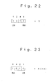
- Transmitted data 10 in a sensor from company A shown in Figure 20 includes binary 13 bits including header information 11 consisting of four bits 11a - 11d, equipment code 12 consisting of one bit, identification code 13 consisting of three bits 13a - 13c, air pressure information 14 consisting of one bit, temperature information 15 consisting of one bit, battery voltage information 16 consisting of one bit, status information 17 consisting of one bit, and control code 18 consisting of one bit.
- Transmitted data 20 in a sensor from company B shown in Figure 21 includes binary 20 bits including header information 21 consisting of four bits 21a - 21d, a control code 22 consisting of one bit, an equipment code 23 consisting of one bit, an identification code 24 consisting of four bits 24a - 24d, air pressure information 25 consisting of three bits 25a - 25c, temperature information 26 consisting of three bits 26a - 26c, battery voltage information 27 consisting of three bits 27a - 27c, and status information 28 consisting of one bit.
- Positions of LSB and MSB may reverse in multiple bits of data of arbitrary information for some manufacturers.
- the top bit of four bits binary data is LSB and the fourth bit from the top represents MSB in transmitted data employed by company C.
- binary data when binary data is "1010", its hexadecimal value is "5".
- the top bit of four bits binary data is MSB and the fourth bit from the top represents LSB in transmitted data employed by company D.
- binary data when binary data is "1010", its hexadecimal value is "A (decimal value: 10)".
- the different modulation method is used when the transmission involves radio waves.
- a transmission method between a sensor and a monitor varies among manufacturers as stated above. This made a problem when a tire is replaced with another tire embedded with a sensor from a manufacturer different from that embedded in the first tire in such a case as a flat tire. The sensor in the tire to be used is unable to communicate with a monitor used to communicate till then. This required replacement of the entire system.
- the object of the present invention is to provide a tire monitoring system, its monitor receiver, a monitor and a sensor for monitoring conditions of a tire even when a tire is replaced with another tire fixed with a sensor employing a transmission method different from that employed by a monitor.
- the present invention provides a tire monitoring system including sensors, each of which is provided for each of the tires equipped to a vehicle and detects conditions of the tire and wirelessly sends the detected result, and a monitor with a monitor receiver, which receives the detected result sent from each of said sensors, for monitoring conditions of each of said tires on the basis of said detected result received by the monitor receiver; wherein at least either said sensor or said monitor includes: a storage unit for storing more than two types of transmission method information for a data communication between said sensor and said monitor; and switch means for selecting one type of transmission method information from said stored transmission method information and setting a data communication with a transmission method on the basis of the selected transmission method information available.
- the tire monitoring system has a storage unit and switch means provided with either or both of the sensors and the monitor.
- the switch means enables the same transmission method to be set for sensors and a monitor.
- the switch means selects a transmission method from multiple types of transmission methods stored in the storage unit and sets a data communication with this transmission method available.
- the switch means switches a transmission method to what is common to all the sensors fixed to respective tires or to a transmission method individually for each sensor.
- the present invention provides the abovementioned tire monitoring system, including means for carrying out a data communication by using radio waves between said sensors and said monitor, wherein said switch means has means for switching frequencies of radio waves used in said data communication.
- the tire monitoring system carries out a data communication by using radio waves between sensors and a monitor, wherein a switch means can switch frequencies of radio waves used in a data communication. This enables a data communication to be carried out after replacement of a tire in the same way as before the replacement even if a tire is replaced with another tire fixed with a sensor using a transmission frequency different from that used in the sensor fixed to the tire before the replacement.
- the present invention provides the abovementioned tire monitoring system, wherein said transmission method information includes at least one type of information of communication protocol information, modulation method information, and demodulation method information.
- the tire monitoring system includes at least one type of information of communication protocol information, modulation method information, and demodulation method information as said transmission method information, it can switch transmission methods on the basis of these types of information. For example, when the tire monitoring system has information on communication protocols as communication protocol information, information on modulation methods as modulation method information, and information on demodulation methods as demodulation method information, it can set multiple transmission methods by combining them. If the tire monitoring system requires no modulation method information or no demodulation method information, it needs not store the unnecessary information.
- the present invention provides the abovementioned tire monitoring system, wherein said transmission method information includes data transfer bit rate information and transferred data format information.
- the tire monitoring system includes data transfer bit rate information and transferred data format information as said transmission method information, it can respond to a situation and establish a data communication even if data transfer bit rate or a transferred data format changes.
- the present invention provides the abovementioned tire monitoring system, wherein said monitor is provided inside said vehicle.
- a monitor provided inside a vehicle carries out a data communication with a sensor in each tire and detects conditions of each tire.
- the present invention provides the abovementioned tire monitoring system, wherein said sensor includes means for detecting an air pressure in a tire and sending the detected result.
- a sensor in each tire detects an air pressure in the tire and sends the detected result to a monitor.
- the present invention provides a monitor receiver in a tire monitoring system including sensors, each of which is provided for each of the tires equipped to a vehicle and detects conditions of the tire and wirelessly sends the detected result, and a monitor with said monitor receiver, which receives the detected result sent from each of said sensors, for monitoring conditions of said tires on the basis of said detected result received by the monitor receiver; wherein said monitor receiver includes:
- the monitor receiver in the tire monitoring system is provided with a storage unit and switch means.
- the switch means can set a transmission method for receiving data sent from a sensor.
- switch means selects a transmission method from multiple types of transmission methods stored in the storage unit and sets the transmission method to be used for receiving data sent from a sensor.
- the switch means switches a transmission method to what is common to all the sensors fixed to respective tires or to a transmission method individually for each sensor.
- the present invention provides the monitor receiver in the abovementioned tire monitoring system, including means for carrying out a data communication by using radio waves with said sensors, wherein said switch means has means for switching frequencies of radio waves used in said data communication.
- the monitor receiver in the tire monitoring system receives data including a detected result sent from a sensor by using radio waves.
- the switch means can switch frequencies of radio waves to be used in a data communication. This enables data to be received after replacement of a tire in the same way as before the replacement even if a tire is replaced with another tire fixed with a sensor using a transmission frequency different from that used in the sensor fixed to the tire before the replacement.
- the present invention provides the monitor receiver in the abovementioned tire monitoring system, wherein said transmission method information includes at least either communication protocol information or demodulation method information.
- the monitor receiver in the tire monitoring system includes at least either of communication protocol information and demodulation method information for said transmission method information, it can switch transmission methods on the basis of these types of information. For example, when the tire monitoring system has information on communication protocols as communication protocol information and information on demodulation methods as demodulation method information, it can set multiple transmission methods by combining them.
- the present invention provides the monitor receiver in the abovementioned tire monitoring system, wherein said transmission method information includes data transfer bit rate information and transferred data format information.
- the monitor of the tire monitoring system includes data transfer bit rate information and transferred data format information as said transmission method information, it can respond to a situation and receive data sent from a sensor even if data transfer bit rate or a transferred data format changes.
- the present invention provides the monitor receiver in the abovementioned tire monitoring system, wherein said switch means includes means for selecting one type of transmission method information from said more than two types of transmission method information and setting a data communication with a transmission method based on the selected transmission method information available, individually for each of the sensors.
- said switch means can set a transmission method individually for each sensor.
- the switch means selects one type of transmission method information from said more than two types of transmission method information individually for each of the sensors and sets a data communication with a transmission method based on the selected transmission method information available individually for each of the sensors.
- the present invention provides the monitor receiver in the tire monitoring system including communication means for carrying out a data communication in a time sharing method with each of said sensors, wherein said switch means includes means for setting one of said transmission methods available individually for a transmission time for each of said time-sharing sensors.
- the monitor receiver in the tire monitoring system receives data sent from each sensor in time sharing method and sets one of said transmission methods available individually for a transmission time for each of said time-sharing sensors.
- the present invention provides the monitor receiver in the abovementioned tire monitoring system; wherein said switch means includes:
- a data communication with a transmission method on the basis of transmission method information stored in said storage unit by a control unit is set available, and data sent from said sensor with any of more than two demodulation methods is received on the basis of an instruction from said control unit.
- said control unit is switched to the default state by said switch after a sensor is changed, data sent from a sensor is received by switching more than two demodulation methods one after the other by said control unit and an available transmission method is determined by automatically determining a transmission method corresponding to said sensor on the basis of predetermined information in the received data.
- the present invention provides the monitor receiver in the abovementioned tire monitoring system, wherein said storage unit stores information representing the type of a sensor and transmission method information in sensor's own identification information sent by the sensor in association with each other, wherein said control unit has means for automatically determining a transmission method corresponding to said sensor on the basis of sensor's identification information included in data received from said sensor.
- a control unit automatically determines a transmission method corresponding to a sensor on the basis of sensor's identification information included in data received from the sensor.
- the present invention provides the monitor receiver in the abovementioned tire monitoring system, including at least two or more of amplitude modulation (AM), amplitude shift keying (ASK), frequency modulation (FM), frequency shift keying (FSK), phase modulation (PM) and phase shift keying (PSK) as said demodulation method.
- AM amplitude modulation
- ASK amplitude shift keying
- FM frequency modulation
- FSK frequency shift keying
- PM phase modulation
- PSK phase shift keying
- the monitor receiver in the tire monitoring system can carry out demodulation in association with each of at least two or more of modulation methods of radio waves modulated by using amplitude modulation (AM), amplitude shift keying (ASK), frequency modulation (FM), frequency shift keying (FSK), phase modulation (PM) and phase shift keying (PSK) as said demodulation method.
- AM amplitude modulation
- ASK amplitude shift keying
- FM frequency modulation
- FSK frequency shift keying
- PM phase modulation
- PSK phase shift keying
- the present invention provides the monitor receiver in the abovementioned tire monitoring system including means for displaying at least a part of data received from said sensor.
- the monitor receiver in the tire monitoring system according to the present invention can display at least a part of data received from a sensor.
- the present invention provides a monitor of a tire monitoring system including sensors, each of which is provided for each of the tires equipped to a vehicle and detects conditions of the tire and wirelessly sends the detected result, and a monitor with a monitor receiver, which receives the detected result sent from each of said sensors, for monitoring conditions of said tires on the basis of said detected result received by the monitor receiver, wherein said monitor includes any of said monitor receivers.
- the monitor of the tire monitoring system includes said monitor receiver, it can switch transmission methods for receiving data sent from a sensor.
- the switch means switches a transmission method to what is common to all the sensors fixed to respective tires or to a transmission method individually for each sensor.
- the present invention provides the monitor of the abovementioned tire monitoring system including means for requesting from said sensor to send said detected result.
- a sensor In the monitor of the tire monitoring system according to the present invention, a sensor always sends a detected result when the sensor is required to send the detected result.
- the present invention provides a sensor of a tire monitoring system including sensors, each of which is provided for each of the tires equipped to a vehicle and detects conditions of the tire and wirelessly sends the detected result, and a monitor with a monitor receiver, which receives the detected result sent from each of said sensors, for monitoring conditions of said tires on the basis of said detected result received by the monitor receiver, wherein said sensors includes:
- the sensors of the tire monitoring system according to the present invention are provided with a storage unit and switch means.
- the switch means can set a transmission method for sending data from a sensor.
- the switch means selects a transmission method from multiple types of transmission methods stored in the storage unit and sets so that data including a detected result can be sent by using this transmission method.
- the present invention provides a sensor of the abovementioned tire monitoring system including means for carrying out a data communication with said monitor by using radio waves.
- the sensor of the tire monitoring system sends data including a detected result by using radio waves.
- switch means can switch frequencies of radio waves used in the data communication. This enables a data transfer to be carried out after replacement of a tire in the same way as before the replacement even if the sensor is used for a vehicle equipped with a monitor using a different frequency as a transmission frequency.
- the present invention provides the sensor of the abovementioned tire monitoring system, wherein said transmission method information includes at least either communication protocol information or modulation method information.
- the sensor of the tire monitoring system includes at least either communication protocol information or modulation method information as said transmission method information
- transmission methods can be switched on the basis of the information.
- the sensor of the tire monitoring system has information on communication protocols as communication protocol information and information on modulation methods as modulation method information, it can set multiple transmission methods by combining them.
- the present invention provides the sensor of the abovementioned tire monitoring system, wherein said transmission method information includes data transfer bit rate information and transferred data format information.
- the sensor of the tire monitoring system includes data transfer bit rate information and transferred data format information as said transmission method information, it can respond to changing of data transfer bit rate or a transferred data format.
- the present invention provides the sensor of the abovementioned tire monitoring system including means for detecting an air pressure in a tire and sending the detected result.
- the sensor of the tire monitoring system detects an air pressure in a tire and sends data including the detected result to a monitor.
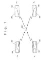
- Figure 1 is a block diagram illustrating a tire monitoring system of the first embodiment according to the present invention.
- Figure 2 is a block diagram illustrating an electric circuit of a sensor of the first embodiment according to the present invention.
- Figure 3 is a block diagram illustrating an electric circuit of a monitor of the first embodiment according to the present invention.
- the reference number 100 denotes a sensor
- 200 denotes a monitor
- 300 denotes a tire equipped to a vehicle.
- a sensor 100 is provided inside a tire 300, detects the air pressure in the tire 300 and wirelessly sends the detected result to a monitor 200.
- an electric circuit of the sensor 100 includes a sensor unit 110, a central processing unit 120, a buffer circuit 130, an oscillation unit 140, an antenna 150 and a battery 160.
- the sensor unit 110 includes an air pressure sensor 111 and an A/D converting circuit 112.
- the air pressure sensor 111 detects a pressure of air filling up the tire 300 and outputs this detected result in an analog electronic signal.
- a commercially available device can be used as the air pressure sensor 111.
- the A/D converting circuit 112 converts the analog electric signal output from the air pressure sensor 111 into a digital signal and outputs the digital signal to a CPU 121.
- the digital signal corresponds to a value of the air pressure in a tire 300.
- the central processing unit 120 includes a known CPU 121, a digital/analog (hereinafter referred to D/A) converting circuit 122 and a storage unit 123.
- D/A digital/analog
- the CPU 121 operates based on a program stored in semiconductor memory of the storage unit 123.
- the CPU 121 When the CPU 121 is supplied with electric energy and driven, it sends sensed data from the sensor unit 110 to the monitor 200 at every predetermined time (for example, five minuets).
- the storage unit 123 previously stores identification information specific to the sensor 100. The CPU 121 sends this identification information to the monitor 200 along with the sensed data.
- the storage unit 123 includes ROM recording a program for operating CPU 121 and electrically erasable programmable nonvolatile semiconductor memory such as EEPROM (electrically erasable programmable read-only memory).
- the storage unit 123 previously stores identification information specific to each sensor 100 (hereinafter referred to sensor ID) in the region specified as inerasable in the storage unit 123 when it is manufactured.
- the buffer circuit 130 includes a memory circuit using FIFO or the like.
- the buffer circuit 130 temporally accumulates binary serial sent data output from the D/A converting circuit 122 and outputs it to the oscillation unit 140.
- the oscillation unit 140 includes an oscillation circuit 141, a modulation circuit 142 and a high frequency amplification circuit 143.
- the oscillation unit 140 modulates carrier waves oscillated at the oscillation circuit 141 formed by a known PLL circuit or the like, for example, carrier waves of a frequency in 315 MHz band, at the modulation circuit 142 on the basis of sent data input from the buffer circuit 130, and supplies them as a high frequency current of a frequency in 315 MHz band to an antenna 150 via the high frequency amplification circuit 143.
- the Modulation circuit 142 amplitude-modulates (AM) carrier waves on the basis of sent data input from the buffer circuit 130 and outputs them to the high frequency amplification circuit 143.
- AM amplitude-modulates
- the modulation method in the modulation circuit 142 is not limited to amplitude-modulation (AM), and other modulation methods including amplitude shift keying (ASK), frequency modulation (FM), frequency shift keying (FSK), phase modulation (PM) and phase shift keying (PSK) may be used.
- AM amplitude-modulation
- ASK amplitude shift keying
- FM frequency modulation
- FSK frequency shift keying
- PM phase modulation
- PSK phase shift keying
- the antenna 150 is for communicating with the monitor 200 using radio waves.
- the antenna 150 is adjusted to a predetermined frequency in 315 MHz band in this embodiment.
- the battery 160 includes secondary battery or the like, and supplies electric energy necessary to drive the sensor 100 to each unit.
- a sensor 100 is embedded in a tire 300 when the tire 300 is manufactured, it is needless to say that an IC chip or other components are designed so as to bear the heat of vulcanization.
- the monitor 200 is placed near the driver seat of a vehicle.
- the monitor 200 includes antennas 201, 202, an FM receiving unit 203, an AM receiving unit 204, a receiving buffer 205, a central processing unit 206, memory 207, an operating unit 208, a switch 209, a display controlling unit 210, a display 211, and a power source unit 212.
- a monitor receiver includes the abovementioned antennas 201, 202, FM receiving unit 203, AM receiving unit 204, receiving buffer 205, central processing unit 206, memory 207, operating unit 208, switch 209 and power source 212.
- the antennas 201, 202 are adjusted to the same frequency as the sending frequency of the sensor 100.
- the antenna 201 is connected to an input side of the FM receiving unit 203 and the antenna 202 is connected to an input side of the AM receiving unit 204.
- the FM receiving unit 203 receives radio waves of a predetermined frequency that went through frequency modulation (FM) or frequency shift keying (FSK) via the antenna 201, demodulates the received signal into binary serial digital data, and outputs the received data to the receiving buffer 205.
- the FM receiving unit 203 switches demodulation methods, i.e., switches between receiving radio waves which went through frequency modulation (FM) or receiving radio waves which went through frequency shift keying (FSK), on the basis of a control signal from the central processing unit 206.
- the FM receiving unit 203 can scan a predetermined range of a receiving frequency on the basis of a control signal from the central processing unit 206 and lock a receiving frequency to any frequency within a predetermined range. It is needless to say that frequencies in 315 MHz band are included as a receivable frequency band in the FM receiving unit 203.
- the AM receiving unit 204 receives radio waves of a predetermined frequency that went through amplitude modulation (AM) or amplitude shift keying (ASK) via the antenna 202, demodulates the received signal into binary serial digital data, and outputs the received data to the receiving buffer 205.
- the AM receiving unit 204 switches demodulation methods, i.e., switches between receiving radio waves which went through amplitude modulation (AM) or receiving radio waves which went through amplitude shift keying (ASK), on the basis of a control signal from the central processing unit 206.
- the AM receiving unit 204 can scan a predetermined range of a receiving frequency on the basis of a control signal from the central processing unit 206 and lock a received frequency to any frequency within a predetermined range. It is needless to say that frequencies in 315 MHz band are included as a receivable frequency band in the AM receiving unit 204.
- the receiving buffer 205 temporally stores serial digital data output from the FM receiving unit 203 and the AM receiving unit 204, and outputs the data to the central processing unit 206 according to an instruction from the central processing unit 206.
- a main component of the central processing unit 206 is a known CPU.
- the central processing unit 206 operates on the basis of a program stored in the memory 207.
- the central processing unit 206 When the central processing unit 206 is supplied with electric energy and driven, it analyzes sensed data received from the sensor 100 and displays it on the display 211 via the display controlling unit 210.
- the central processing unit 206 inputs information or signals from the operating unit 208 and the switch 209, initializes the transmission method with the sensor 100, and communicates with each sensor 100 with the initialized transmission method.
- the memory 207 includes ROM recording a program for operating a CPU in the central processing unit 206 and electrically erasable programmable nonvolatile semiconductor memory such as EEPROM (electrically erasable programmable read-only memory).
- EEPROM electrically erasable programmable read-only memory
- the transmission methods table represents information including communication protocols, demodulation methods of received radio waves, transfer bit rate, data format and frequencies in association with the abovementioned sensor ID specific to each sensor 100.
- a sensor ID needs not be represented by the whole of the sensor ID. It may be represented by only a part of the information that can identify a transmission method in a data transfer or information representing the type of the product or the manufacturer's name. This may reduce processing time in extracting a transmission method.
- the transmission methods table enables data update including change, addition or deletion of data via the operating unit 208.
- the transmission methods table shown in Figure 4 is designed to identify the difference between transmission methods by the top two digits of a character string forming each sensor ID.
- Each transmission method is represented in association with a sensor ID as a combination of multiple types of protocol 1-n (n is a natural number of 2 or more), multiple types of demodulation methods (amplitude modulation (AM), amplitude shift keying (ASK), frequency modulation (FM), frequency shift keying (FSK), phase modulation (PM) and phase shift keying (PSK)), multiple types of transfer bit rate 1-n, multiple types of data format 1-n, multiple frequencies f1-fn.
- the abovementioned communication protocol is information representing a protocol of sending/receiving data with the sensor 100.
- the operating unit 208 includes a keyboard with multiple switches, for example.
- the operating unit 208 is for inputting information for initialization or the ID of the sensor 100.
- the switch 209 is for ordering the central processing unit 206 to start initialization.
- the display control unit 210 displays a value of the air pressure in each tire 300 in association with an equipped place of each tire 300 on the display 211 based on data input from the central processing unit 206.
- the power source unit 212 is supplied with power from a battery mounted on the vehicle, regulates this power to a right voltage for each unit forming the monitor 200 and supplies the power to each unit.
- the ID of the sensor 100 in each tire 300 needs to be previously input in the monitor 200 so that the monitor 200 can identify the type of the sensor 100 in each tire 300 in association with the equipped place of the tire 300.
- it is required to check the ID of the sensor 100 provided for each tire 300, turn on the switch 209 of the monitor 200, input the ID of each sensor 100 and turn off the switch 209 after the input, before the system is used.
- the central processing unit 206 of the monitor 200 determines whether the setting switch (switch 209) is turned on or not (SA1). If the switch 209 is turned off, the central processing unit 206 proceeds to a monitor process SA5 to be described later. If the switch 209 is turned on, the central processing unit 206 performs initialization.
- the central processing unit 206 performs a sensor place setting input for importing a sensor ID input from the operating unit 208 in association with an equipped place of the tire 300 (SA2). Then the central processing unit 206 extracts a transmission method corresponding to each sensor ID from a transmission methods table (SA3) and stores information on the extracted transmission method in memory 207 in association with the sensor ID (SA4).
- SA3 transmission methods table
- the central processing unit 206 performs the monitor process.
- the central processing unit 206 analyzes the received data received from each sensor 100 and stored in the receiving buffer 205. With this analysis, the central processing unit 206 determines a sensor ID included in the received data, obtains detected data, i.e., the air pressure in the tire 300 and displays this on the display 211 via the display control unit 210.
- the monitor 200 has a transmission methods table and the central processing unit 206 can set a transmission method so that the same transmission method is used by each sensor 100 and the monitor 200.
- the central processing unit 206 can set a transmission method for each of the sensors fixed to the respective tires. For example, as shown in Figure 6, even if only the rear right tire of a vehicle is replaced with a tire 300A provided with another type of sensor 100A, a data communication in the transmission method for the sensor 100A can be made available.
- the monitor 200 may be adapted to switch transmission methods in common with all the sensors 100 fixed to the respective tires 300. In other words, the monitor 200 may be adapted to switch transmission methods only when the sensors 100 in all the tires 300 are the same type.
- the system is adapted to have the sensor 100 only including the air pressure sensor 111 in this embodiment, the system may have the sensor 100 provided with the sensor unit 100, which detects the temperature, the humidity, distortion and the acceleration of the tire 300, for sending the detected value.
- the system can respond to the transmission by providing the monitor 200 with a receiving unit supporting different transmission frequency bands and by adding information on a used frequency to the abovementioned transmission methods table.
- the system may switch or branch off a single antenna to be shared for the purpose of the antenna 201 for the FM receiving unit 203 and the antenna 202 for the AM receiving unit 204.
- the system can be adapted to include a sending unit or a receiving unit adjusted to modulation methods and demodulation methods other than the abovementioned ones, for example, phase modulation (PM) or phase shift keying (PSK) and switch with a sending unit or a receiving unit for other modulation methods or demodulation methods.
- a sending unit or a receiving unit adjusted to modulation methods and demodulation methods other than the abovementioned ones, for example, phase modulation (PM) or phase shift keying (PSK) and switch with a sending unit or a receiving unit for other modulation methods or demodulation methods.
- PM phase modulation
- PSK phase shift keying
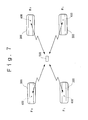
- Figure 7 is a block diagram illustrating a tire monitoring system of the second embodiment according to the present invention.
- Figure 8 is a block diagram illustrating an electric circuit of a sensor of the second embodiment according to the present invention.
- Figure 9 is a block diagram illustrating an electric circuit of a monitor of the second embodiment according to the present invention.
- the same components as those in the abovementioned first embodiment are denoted by the same reference numbers and omitted from the following description. Differences between the second embodiment and the first embodiment are that the second embodiment includes a monitor 500 that enables transmission of radio waves and a passive sensor 400 that receives radio waves sent from monitor 500 and operates on the energy.
- the tire monitoring system of the second embodiment includes the sensor 400 provided for each tire 300 and the monitor 500.
- the senor 400 includes a sensor unit 110, a central processing unit 120, a buffer circuit 130, an oscillation unit 140, an antenna 150, an antenna switch 170, a rectification circuit 180 and a detector 190.
- the second embodiment is provided with the antenna switch 170, the rectification circuit 180 and the detector 190 in addition to the configuration of the first embodiment.
- the antenna switch 170 includes an electronic switch or the like, for example.
- the antenna switch 170 switches between a connection of the antenna 150 with the rectification circuit 180 and the detector 190 and a connection of the antenna 150 with the oscillation unit 140 under the control of the central processing unit 120.
- the rectification circuit 180 including diodes 181, 182, a condenser 183 for smoothing or storage, and a register 184, forms a known full-wave rectification circuit.
- the antenna 150 is connected to the input side of the rectification circuit 180 via the antenna switch 170.
- the rectification circuit 180 rectifies a high frequency current induced at the antenna 150 into a direct current and outputs this current as a driving power source of the central processing unit 120, the detector 190, the oscillation unit 140 and the sensor unit 110.
- a program stored in the storage unit 123 of the central processing unit 120 is also different from that of the first embodiment.
- a CPU 121 of the central processing unit 120 sends a detected result only when a sending request instruction designating its own sensor ID is input from the detector 190.
- the monitor 500 includes receiving antennas 201, 202, an FM receiving unit 203, an AM receiving unit 204, a receiving buffer 205, a central processing unit 206, memory 207, an operating unit 208, a switch 209, a display control unit 210, a display 211, a power source unit 212, a sending buffer 213, an FM sending unit 214, an AM sending unit 215 and sending antennas 216, 217.
- the second embodiment is provided with the sending buffer 213, the FM sending unit 214, the AM sending unit 215 and the sending antennas 216, 217 in addition to the configuration of the first embodiment.
- the sending buffer 213 is connected between the central processing unit 206 and the FM sending unit 214, the AM sending unit 215.
- the sending buffer 213 temporally stores serial digital data representing the abovementioned sending request instruction output from the central processing unit 206 and outputs the data to the FM sending unit 214 or the AM sending unit 215 according to an instruction from the central processing unit 206.
- the FM sending unit 214 inputs sending data from the sending buffer 213 according to an instruction from the central processing unit 206 and sends the data in the frequency and the modulation method indicated by the central processing unit 206.
- the AM sending unit 215 inputs sending data from the sending buffer 213 according to an instruction from the central processing unit 206 and sends the data in the frequency and the modulation method indicated by the central processing unit 206.
- the central processing unit 206 indicates a demodulation method in a transmission methods table as a modulation method to the FM sending unit 214 and the AM sending unit 215.
- Data format information in a transmission methods table stored in the memory 207 includes information on data format to be sent by the sensor 400 and received data format that can be received by the sensor 400.
- a program stored in the memory 207 for operating the central processing unit 206 is also different from that of the first embodiment.
- the central processing unit 206 sends the abovementioned sending request instruction by designating each sensor 400 with a sensor ID in a transmission method corresponding to each sensor 400.
- the central processing unit 206 generates sending data in a data transfer rate and a data format corresponding to each sensor 400 and outputs the data to the sending buffer 213.
- the ID of the sensor 400 in each tire 300 needs to be previously input in the monitor 500 so that the monitor 500 can identify the type of the sensor 400 in each tire 300 in association with the equipped place of the tire 300.
- it is required to check the ID of the sensor 400 provided for each tire 300, turn on the switch 209 of the monitor 500, input the ID of each sensor 400 and turn off the switch 209 after the input, before the system is used.
- the monitor 500 communicates with the sensors 400 starting at the first sensor and through to the fourth sensor in order.
- Transmission time t1 from the monitor 500 to the sensor 400 is set to a time for supplying energy enough for driving the sensor 400 and for completely sending the sending request instruction.
- Receiving time t2 is set to a time for completely receiving data sent from the sensor 400.
- the monitor 500 has a transmission methods table and the central processing unit 206 can set a transmission method so that the same transmission method is used by each sensor 400 and the monitor 500.
- the central processing unit 206 can set a transmission method for each of the sensors fixed to the respective tires. If a tire is replaced with the tire 300 provided with another type of sensor 400, a data communication in the transmission method for the sensor 400 can be made available.
- the senor 400 needs no battery. This saves time and effort for servicing such as battery change.
- each sensor 400 is previously input to the monitor 500 in association with the equipped place of the tire 300 in the abovementioned second embodiment, the ID of each sensor 400 may be input without being associated with the equipped place of the tire 300 in order only to detect an abnormal event of air pressure without identifying the tire 300.
- the monitor 500 may also be adapted to automatically detect the ID of each sensor 400.
- a program of the sensor 400 is set to send predetermined information including its own sensor ID when it receives a sending request instruction with no ID designated.
- a program of the monitor 500 is set to send a sending request instruction in each transmission method included in a transmission methods table and obtain the sensor ID of each sensor 400 when the switch 209 is turned on or the monitor 500 starts.
- Figure 11 is a block diagram illustrating a tire monitoring system of the third embodiment according to the present invention.
- Figure 12 is a block diagram illustrating an electric circuit of a monitor of the third embodiment according to the present invention.
- the same components as those in the abovementioned first embodiment are denoted by the same reference numbers and omitted from the following description. Differences between the third embodiment and the first embodiment are that the third embodiment has a monitor 600 including a main monitor 610 and detecting units 620A-620D provided in association with the respective sensors 100.
- Each of detecting units 620A-620D is provided near each tire 300, for example inside a wheel house, and connected to the main monitor 610 via a cable.
- the main monitor 610 is placed near the driver seat of the vehicle.
- the main monitor 610 includes a central processing unit 206, memory 207, an operating unit 208, a switch 209, a display controlling unit 210, a display 211 and a power source unit 212.
- Each of detecting units 620A-620D includes antennas 201, 202, an FM receiving unit 203, an AM receiving unit 204 and a receiving buffer 205.
- the central processing unit 206 of the main monitor 610 is adapted to output a control signal to each of the detecting units 620A-620D.
- the switch 209 on the monitor 600 is formed by a momentary switch.
- a program of the central processing unit 206 stored in the memory 207 which is also different from that of the first embodiment, is adapted to recognize the correspondence between each of the detecting units 620A-620D and the tire 300 equipped to each place of the vehicle.
- Transmitting power of the sensor 100 is set to a minimum value for radio waves to reach the detecting units 620A-620D provided in association with each sensor 100. Therefore, each of the detecting units 620A-620D receives only radio waves sent from the sensor 100 associated with the unit without receiving any radio wave sent from other sensors 100.
- the tire monitoring system in this embodiment does not require the ID of each sensor 100 to be checked and input in the monitor 600.
- the sensor ID of each sensor 400 is imported in the monitor 600 when a driver turns on the switch 209 to start to use the monitor 600 or after changing the tire 300.
- the monitor 600 when the monitor 600 is supplied with driving power and starts operating, it keeps monitoring whether the switch 209 is turned on or not (SB1). If the monitor 600 does not detects that the switch 209 is tuned on, it proceeds to SB5 to be described later and performs a monitor process. If the monitor 600 detect that the switch 209 is turned on, it scans all the frequencies that can be received by the FM receiving unit 203 and the AM receiving unit 204 in each of the detecting units 620A-620D, detects radio waves sent form the sensor 100, and determines the transmission method of the sensor 100 corresponding to each of the detecting units 620A-620D.
- the central processing unit 206 scans by changing demodulation methods in the FM receiving unit 203 and the AM receiving unit 204, sequentially analyzes data stored in the receiving buffer 205. The central processing unit 206 repeats this process until it detects the sensor 100 (SB2, SB3).
- the central processing unit 206 stores the ID and the transmission method of the detected sensor 100 in the memory 207 in association with the place where the tire 300 is equipped (SB4).
- the central processing unit 206 in the monitor 600 performs a monitor process (SB5) .
- the central processing unit 206 obtains detected data, i.e., an air pressure value in the tire 300, included in received data received from each sensor 100 and stored in the receiving buffer 205 in each of the detecting units 620A-602D and displays the data on the display 211 via the display control unit 210.
- the monitor 600 has a transmission methods table and the central processing unit 206 can set a transmission method so that the same transmission method is used by each sensor 100 and each of the detecting units 620A-620D in the monitor 600.
- the central processing unit 206 automatically sets a transmission method individually for each sensor 100 fixed to each tire 300. If any tire 300 is replaced with another tire 300 provided with a sensor 100 of different type, a data communication with a transmission method of this sensor 100 is automatically made available.
- the third embodiment is adapted to set a transmission method by detecting the ID of the sensor 100 when a driver or the like turns on the switch 209
- the switch 209 may be geared with the starter switch of the vehicle.
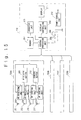
- Figure 14 is a block diagram illustrating a tire monitoring system of the fourth embodiment according to the present invention.
- Figure 15 is a block diagram illustrating an electric circuit of a monitor of the fourth embodiment according to the present invention.
- the same components as those in the abovementioned second embodiment are denoted by the same reference numbers and omitted from the following description. Differences between the fourth embodiment and the second embodiment are that the fourth embodiment has the monitor 700 including the main monitor 710 and the detecting units 720A-720D provided in association with the respective sensors 400.
- Each of the detecting units 720A-720D is provided near each tire 300, for example inside a wheel house, and connected to the main monitor 710 via a cable.
- the main monitor 710 is placed near the driver seat of the vehicle.
- the main monitor 710 includes a central processing unit 206, memory 207, an operating unit 208, a switch 209, a display controlling unit 210, a display 211 and a power source unit 212.
- Each of the detecting units 720A-720D includes receiving antennas 201, 202, an FM receiving unit 203, an AM receiving unit 204, a receiving buffer 205, an FM sending unit 214, an AM sending unit 215 and sending antennas 216, 217.
- the central processing unit 206 of the main monitor 710 is adapted to output a control signal to each of the detecting units 720A-720D.
- the switch 209 of the monitor 700 is formed by a momentary switch.
- a program of the central processing unit 206 stored in the memory 207 which is also different from that of the second embodiment, is adapted to recognize the correspondence between each of the detecting units 720A-720D and the tire 300 equipped to each place of the vehicle.
- Transmitting power of the sensor 400 is set to a minimum value for radio waves to reach the detecting units 720A-720D provided in association with each sensor 400. Therefore, each of the detecting units 720A-720D receives only radio waves sent from the sensor 400 associated with the unit without receiving any radio wave sent from other sensors 400.
- the sensor ID of each sensor 400 is imported in the monitor 700 when a driver turns on the switch 209 to start to use the monitor 700 or after changing the tire 300.
- the monitor 700 When the monitor 700 is supplied with driving power and starts operating, it keeps monitoring whether the switch 209 is turned on or not. If the monitor 700 does not detect that the switch 209 is tuned on, it performs a monitor process to be described later.
- the central processing unit 206 sends the abovementioned sending request instruction by scanning all the frequencies listed in a transmission methods table by the FM sending unit 214 and the AM sending unit 215 in each of the detecting units 720A-720D, while receiving radio waves of the frequencies sent by the FM receiving unit 203 and the AM receiving unit 204, detecting radio waves sent from the sensor 400 and determining the transmission method of the sensor 400 corresponding to each of the detecting units 720A-720D.
- the central processing unit 206 scans by changing modulation methods in the FM sending unit 214 and the AM sending unit 215 and demodulation methods in the FM receiving unit 203 and the AM receiving unit 204, sequentially analyzes data stored in the receiving buffer 205. The central processing unit 206 repeats this process until it detects the sensor 400.
- the monitor 700 communicates with the sensors 400 starting at the first sensor and through to the fourth sensor in order.
- Transmission time t1 from the monitor 700 to the sensor 400 is set to a time for supplying energy enough for driving the sensor 400 and for completely sending the sending request instruction.
- Receiving time t2 is set to a time for completely receiving data sent from the sensor 400.
- the central processing unit 206 stores the ID and the transmission method of the detected sensor 400 in the memory 207 in association with the place where the tire 300 is equipped.
- the central processing unit 206 in the monitor 700 performs a monitor process.
- the central processing unit 206 obtains detected data, i.e. , an air pressure value in the tire 300, included in received data received from each sensor 400 and stored in the receiving buffer 205 in each of the detecting units 620A-620D and displays the data on the display 211 via the display control unit 210.
- the monitor 700 has a transmission methods table and the central processing unit 206 automatically sets a transmission method so that the same transmission method is used by each sensor 400 and the monitor 700.
- the central processing unit 206 individually sets a transmission method for each sensor 400 fixed to each tire 300. If a tire is replaced with the tire 300 provided with another type of sensor 400, a data communication with the transmission method for the sensor 400 is automatically made available.
- the senor 400 needs no battery. This saves time and effort in servicing such as battery change.
- the switch 209 may be geared with the starter switch of a vehicle and automatically set when the vehicle starts.
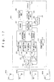
- Figure 16 is a block diagram illustrating a tire monitoring system of the fifth embodiment according to the present invention.
- Figure 17 is a block diagram illustrating an electric circuit of a monitor of the fifth embodiment according to the present invention.
- the same components as those in the abovementioned second embodiment are denoted by the same reference numbers and omitted from the following description. Differences between the fifth embodiment and the second embodiment are that the fifth embodiment has a monitor 800 including a main monitor 810 and antenna units 820A-820D provided in association with respective sensors 400.
- Each of the antenna units 820A-820D includes an antenna 821 adjusted to a frequency of radio waves that is available for the main monitor 810 to send and receive.
- Each of the antenna units 820A-820D is provided near each tire 300, for example inside a wheel house, and connected to the main monitor 810 via a coaxial cable for high frequency.
- the main monitor 810 includes an FM receiving unit 203, an AM receiving unit 204, a receiving buffer 205, a central processing unit 206, memory 207, an operating unit 208, a switch 209, a display controlling unit 210, a display 211, a power source unit 212, a sending buffer 213, an FM sending unit 214, an AM sending unit 215 and electronic switches 221-224.
- each terminal is connected so that the antenna 821 of any one unit of the antenna units 820A-820D can be connected with any one of the FM receiving unit 203, the AM receiving unit 204, the FM sending unit 214 and the AM sending unit 215 on the basis of a control signal from the central processing unit 206.
- the antenna 821 of any one of the antenna units 820A-820D is selected by an electronic switch 224 with four contacts for each circuit and connected with an armature of an electronic switch 223 with two contacts for each circuit.
- a contact of the electronic switch 223 is connected with an armature of the electronic switch 221 for switching between connections to the FM receiving unit 203 and the AM receiving unit 204.
- the other contact of the electronic switch 223 is connected with an armature of the electronic switch 222 for switching between connections to the FM sending unit 214 and the AM sending unit 215.
- the central processing unit 206 of the main monitor 810 is adapted to output a switch control signal of the electronic switches 221-224 .
- a program of the central processing unit 206 stored in the memory 207 is a program different from that of the second embodiment and adapted to recognize the correspondence between each of the antenna units 820A-820D and the tire 300 equipped to each place of the vehicle.
- the sensor ID of each sensor 400 is imported in the monitor 800 when a driver turns on the switch 209 to start to use the monitor 800 or after changing tire 300.
- monitor 800 When the monitor 800 is supplied with driving power and starts operating, it keeps monitoring whether the witch 209 is turned on or not. If the monitor 800 does not detect that the switch 209 is tuned on, it performs a monitor process to be described later.
- the central processing unit 206 sends the abovementioned sending request instruction by switching the electronic switches 221-224 and scanning all the frequencies listed in a transmission methods table by the FM sending unit 214 and the AM sending unit 215 and receives radio waves of the abovementioned frequency by the FM receiving unit 203 and the AM receiving unit 204.
- the central processing unit 206 scans by changing modulation methods in the FM sending unit 214 and the AM sending unit 215 and demodulation methods in the FM receiving unit 203 and the AM receiving unit 204, sequentially analyzes data stored in the receiving buffer 205. The central processing unit 206 repeats this process until it detects the sensor 400.
- the central processing unit 206 detects radio waves sent from the sensor 400 and determines the transmission method of the sensor 400 corresponding to each of the antenna units 820A-820D.
- the monitor 800 communicates with the sensor 400 starting at the first sensor and through to the fourth sensor in order.
- Transmission time t1 from the monitor 800 to the sensor 400 is set to a time for supplying energy enough for driving the sensor 400 and for completely sending the sending request instruction.
- Receiving time t2 is set to a time for completely receiving data sent from the sensor 400.
- the monitor 800 has a transmission methods table and the central processing unit 206 automatically sets a transmission method so that the same transmission method is used by each sensor 400 and the monitor 800.
- the central processing unit 206 individually sets a transmission method for each sensor 400 fixed to each tire 300. If a tire is replaced with a tire 300 provided with another type of sensor 400, a data communication with the transmission method for sensor 400 is automatically made available.
- the senor 400 needs no battery. This saves time and effort in servicing such as battery change.
- the fifth embodiment is adapted to set a transmission method by detecting the ID of the sensor 400 when a driver or the like turns on the switch 209
- the switch 209 may be geared with the starter switch of a vehicle and automatically set when the vehicle starts.
- FIG. 18 is a block diagram illustrating an electric circuit of a sensor of the sixth embodiment according to the present invention.
- a sensor of the sixth embodiment is the sensor of the abovementioned first embodiment added with a transmission methods switch function included in a monitor of the first or fifth embodiment.
- the sensor 900 in the sixth embodiment includes a sensor unit 110, a central processing unit 901, an operating unit 902, a buffer circuit 130, an AM submitting unit 903, an FM submitting unit 904, sending antennas 905, 906 and a battery 160.
- the central processing unit 901 is configured as the central processing unit 120 of the first embodiment. Differences between the central processing unit 901 and that of the first embodiment are that the central processing unit 901 is adapted to output a control signal to the AM submitting unit 903 and the FM submitting unit 904 on the basis of a switch setting in the operating unit 902 including a small dip switch or a rotary switch, and that the central processing unit 901 has a different program for operating a CPU, and that a transmission methods table is stored in a storage unit in the central processing unit 901.
- a transmission methods table stored in the central processing unit 901 includes information such as a modulation method, a sending frequency, a data transfer bit rate and a transferred data format in association with a set value for a switch of the operating unit 902.
- the central processing unit 901 switches sending frequencies and modulation methods by inputting detected data by the sensor 110 from the sensor 110 at every predetermined time and outputting a control signal to the AM submitting unit 903 and the FM submitting unit 904 on the basis of a switch setting in operating unit 902 and the abovementioned transmission methods table, generates sending data including the detected data and sends the sending data to a monitor.
- the AM submitting unit 903 has the same function as that of AM sending unit 215 of the second embodiment.
- AM submitting unit 903 When AM submitting unit 903 is permitted to send on the basis of a control signal input from the central processing unit 901, it sends sending data input from the buffer circuit 130 in a frequency and a modulation method designated by the central processing unit 901 via the antenna 905.
- the FM submitting unit 904 has the same function as that of the FM sending unit 214 of the second embodiment.
- the FM submitting unit 904 is permitted to send on the basis of a control signal input from the central processing unit 901, it sends sending data input from the buffer circuit 130 in a frequency and a modulation method designated by the central processing unit 901 via the antenna 906.
- the sensor 900 with the abovementioned configuration enables a transmission with a monitor using any of transmission methods listed in the transmission methods table in the abovementioned central processing unit 901, if a switch setting of the operating unit 902 is changed so as to use the same transmission method as that of a monitor mounted on a vehicle when a tire provided with this sensor 900 is equipped to the vehicle or when the tire is manufactured.
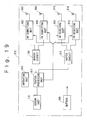
- Figure 19 is a block diagram illustrating an electric circuit of a sensor of the seventh embodiment according to the present invention.
- a sensor of the seventh embodiment is the sensor of the abovementioned sixth embodiment added with a function for receiving data sent from a monitor.
- the sensor 910 in the seventh embodiment includes a sensor unit 110, a central processing unit 911, an operating unit 902, a buffer circuit for sending 130, an AM submitting unit 903, an FM submitting unit 904, sending antennas 905, 906, a buffer circuit for receiving 912, an AM receiving unit 913, an FM receiving unit 914, receiving antennas 915, 916 and a battery 160.
- the central processing unit 911 is configured as the central processing unit 901 of the sixth embodiment. Differences between the central processing unit 911 and that of the sixth embodiment are that the central processing unit 911 is adapted to output a control signal to the AM submitting unit 903, the FM submitting unit 904, the AM receiving unit 913 and the FM receiving unit 914 on the basis of a switch setting in the operating unit 902 including a small dip switch or a rotary switch, and that the central processing unit 911 has a different program for operating a CPU.
- the central processing unit 911 sends its own sensor ID on the basis of data input from the buffer circuit for receiving 912, i.e., an instruction received from a monitor by outputting a control signal to the AM submitting unit 903, the FM submitting unit 904, the AM receiving unit 913 and the FM receiving unit 914 on the basis of a switch setting of the operating unit 902 and the abovementioned transmission methods table and switching frequencies for sending and receiving or modulation methods and demodulation methods, and sends sending data including detected data by the sensor unit 110 by inputting the detected data from the sensor 110.
- the AM receiving unit 913 has the same function as that of the AM receiving unit 204 of the first embodiment and receives radio waves via the antenna 915. At this moment, the AM receiving unit 913 outputs data received in a frequency and a demodulation method designated by the central processing unit 911 to the buffer circuit 912 on the basis of a control signal input from the central processing unit 911.
- the FM receiving unit 914 has the same function as that of FM receiving unit 203 of the first embodiment and receives radio waves via the antenna 916. At this moment, the FM receiving unit 914 outputs data received in a frequency and a demodulation method designated by the central processing unit 911 to the buffer circuit 912 on the basis of a control signal input from the central processing unit 911.
- the sensor 910 with the abovementioned configuration enables a transmission with a monitor using any of transmission methods listed in the transmission methods table in the abovementioned central processing unit 911, if a switch setting of the operating unit 902 is changed so as to use the same transmission method as that of a monitor mounted on a vehicle when a tire provided with this sensor 910 is equipped to the vehicle or when the tire is manufactured.
- the senor 910 operates on energy from battery 160 in the seventh embodiment, the sensor 910 may operate on electric energy by converting radio wave energy received from a monitor into an electric energy as the sensor 400 does in the second embodiment.
- the present invention is not limited to the abovementioned embodiments from the first to the seventh. It is needless to say that systems and devices that are the combinations of the embodiments are also included in the present invention.
- radio waves are used for a wireless communication between a sensor and a monitor in each of the abovementioned embodiments, the wireless communication is not limited to use radio waves and an optical or supersonic wireless communication is possible.
- the present invention enables conditions of a tire to be monitored if a tire is replaced with another tire fixed with a sensor whose transmission method with the monitor is different from that of the earlier one when the tire is replaced with another tire due to a flat tire or the like.
Landscapes
- Engineering & Computer Science (AREA)
- Mechanical Engineering (AREA)
- Computer Networks & Wireless Communication (AREA)
- Arrangements For Transmission Of Measured Signals (AREA)
- Measuring Fluid Pressure (AREA)
- Mobile Radio Communication Systems (AREA)
Abstract
The present invention provides a tire monitoring system, its
monitor receiver, a monitor and a sensor for monitoring conditions
of a tire even when a tire is replaced with another tire fixed with
a sensor employing a transmission method different from that employed
by a monitor. In other words, the present invention has a communication
methods table listing more than two types of transmission method
information for a data communication between a sensor 100 and a monitor
200 stored in a monitor 200 and enables to set a data communication
with any transmission method selected from the transmission methods
table available in a tire monitoring system including sensors 100,
each of which is provided for each of the tires 300 equipped to a vehicle
and wirelessly sends the detected results about conditions of tires
300, and a monitor 200 for monitoring conditions of each of said tires
300 by receiving the detected result sent from each of sensors 100.
Description
The present invention relates to a tire monitoring system and
its monitor receiver, a monitor and a sensor for detecting conditions
of tire including an air pressure.
Physical conditions of a tire including an air pressure in a tire
have to be checked for safety traveling of a vehicle. It takes time
and effort for a man to check tires. A tire monitoring system for
automatically detecting physical conditions of a tire including an
air pressure in a tire has been developed and become available for
passenger vehicles.
The tire monitoring system includes a sensor generally fixed to
a tire for detecting physical conditions of the tire and transmitting
the detected result wirelessly, and a monitor for receiving the data
sent from the sensor.
The sensor is generally provided inside a tire usually by being
fixed to the rim of the tire or built in the tire.
A sensor with a function of storing historical information
including manufacturing or repairing of a tire is also known. This
type of sensor is usually built in a tire to avoid tampering of stored
information.
A tire monitoring system that can be used for automating stability
control in traveling of a vehicle has also been developed. In this
tire monitoring system, a tire is provided with a sensor having a sensor
unit for detecting physical conditions other than an air pressure,
such as distortion, the number of revolutions, and rotation angle speed
of a tire during the traveling.
"TREAD law (Transportation Recall Enhancement, Accountability
and Document Act)" came into effect on November, 2000 in the United
States, and "a partial amendment of Road Trucking Vehicle Law (amended
Road Trucking Vehicle Law)" came into effect on July, 2002 in Japan.
The TREAD law stipulates outlines of a safe vehicle including
more duty to inform a recall or more stringent penalties of negligence
of the duty, more detailed items in a quality label of a tire, duty
to be equipped with a tire air pressure alarm and improvement of child
seats. To meet the duty to be equipped with a tire air pressure alarm
stipulated by TREAD law, various manufacturers are manufacturing and
selling sensors and tire monitoring systems.
The sensor disclosed in National Publication of International
Patent Application No. 8-505939 is known as a conventional example
of sensor.
The remote tire pressure monitoring system disclosed in National
Publication of International Patent Application No. 8-505939 is a
system for displaying a low tire pressure in a vehicle, wherein each
tire has a transmitter with its own code, and wherein a central receiver
in the vehicle identifies a code of each transmitter. The system is
revised so that it restudies the position of a transmitter when a tire
is changed while a vehicle is on the way to a destination or getting
serviced. When an ASIC encoder in each transmitter is manufactured,
it is programmed to send the information with different periods
according to its own code in order to avoid crashing wireless
frequencies between more than two transmitters on a vehicle.
However, as tire monitoring systems have not had a unified
technical standard, the specification of the system varies among
manufacturers.
For example, an identification code of a transmitter is 12 bits,
20 bits or 24 bits in conventional systems. For a different
identification code, a receiving process at the receiving side also
differs.
As another example, a format of transmitted data also varies among
manufacturers as shown in Figures 20 and 21. Transmitted data 10 in
a sensor from company A shown in Figure 20 includes binary 13 bits
including header information 11 consisting of four bits 11a - 11d,
equipment code 12 consisting of one bit, identification code 13
consisting of three bits 13a - 13c, air pressure information 14
consisting of one bit, temperature information 15 consisting of one
bit, battery voltage information 16 consisting of one bit, status
information 17 consisting of one bit, and control code 18 consisting
of one bit.
Transmitted data 20 in a sensor from company B shown in Figure
21 includes binary 20 bits including header information 21 consisting
of four bits 21a - 21d, a control code 22 consisting of one bit, an
equipment code 23 consisting of one bit, an identification code 24
consisting of four bits 24a - 24d, air pressure information 25
consisting of three bits 25a - 25c, temperature information 26
consisting of three bits 26a - 26c, battery voltage information 27
consisting of three bits 27a - 27c, and status information 28 consisting
of one bit.
Positions of LSB and MSB may reverse in multiple bits of data
of arbitrary information for some manufacturers.
For example, as shown in Figure 22, the top bit of four bits binary
data is LSB and the fourth bit from the top represents MSB in transmitted
data employed by company C. In this case, when binary data is "1010",
its hexadecimal value is "5".
On the other hand, as shown in Figure 23, the top bit of four
bits binary data is MSB and the fourth bit from the top represents
LSB in transmitted data employed by company D. In this case, when
binary data is "1010", its hexadecimal value is "A (decimal value:
10)".
Moreover, the different modulation method is used when the
transmission involves radio waves.
A transmission method between a sensor and a monitor varies among
manufacturers as stated above. This made a problem when a tire is
replaced with another tire embedded with a sensor from a manufacturer
different from that embedded in the first tire in such a case as a
flat tire. The sensor in the tire to be used is unable to communicate
with a monitor used to communicate till then. This required
replacement of the entire system.
In view of the above problem, the object of the present invention
is to provide a tire monitoring system, its monitor receiver, a monitor
and a sensor for monitoring conditions of a tire even when a tire is
replaced with another tire fixed with a sensor employing a transmission
method different from that employed by a monitor.
In order to achieve the abovementioned object, the present
invention provides a tire monitoring system including sensors, each
of which is provided for each of the tires equipped to a vehicle and
detects conditions of the tire and wirelessly sends the detected result,
and a monitor with a monitor receiver, which receives the detected
result sent from each of said sensors, for monitoring conditions of
each of said tires on the basis of said detected result received by
the monitor receiver; wherein at least either said sensor or said
monitor includes: a storage unit for storing more than two types of
transmission method information for a data communication between said
sensor and said monitor; and switch means for selecting one type of
transmission method information from said stored transmission method
information and setting a data communication with a transmission
method on the basis of the selected transmission method information
available.
The tire monitoring system according to the present invention
has a storage unit and switch means provided with either or both of
the sensors and the monitor. The switch means enables the same
transmission method to be set for sensors and a monitor. In other words,
in the present invention, the switch means selects a transmission
method from multiple types of transmission methods stored in the
storage unit and sets a data communication with this transmission
method available. At the monitor, the switch means switches a
transmission method to what is common to all the sensors fixed to
respective tires or to a transmission method individually for each
sensor.
The present invention provides the abovementioned tire
monitoring system, including means for carrying out a data
communication by using radio waves between said sensors and said
monitor, wherein said switch means has means for switching frequencies
of radio waves used in said data communication.
The tire monitoring system according to the present invention
carries out a data communication by using radio waves between sensors
and a monitor, wherein a switch means can switch frequencies of radio
waves used in a data communication. This enables a data communication
to be carried out after replacement of a tire in the same way as before
the replacement even if a tire is replaced with another tire fixed
with a sensor using a transmission frequency different from that used
in the sensor fixed to the tire before the replacement.
The present invention provides the abovementioned tire
monitoring system, wherein said transmission method information
includes at least one type of information of communication protocol
information, modulation method information, and demodulation method
information.
As the tire monitoring system according the present invention
includes at least one type of information of communication protocol
information, modulation method information, and demodulation method
information as said transmission method information, it can switch
transmission methods on the basis of these types of information. For
example, when the tire monitoring system has information on
communication protocols as communication protocol information,
information on modulation methods as modulation method information,
and information on demodulation methods as demodulation method
information, it can set multiple transmission methods by combining
them. If the tire monitoring system requires no modulation method
information or no demodulation method information, it needs not store
the unnecessary information.
The present invention provides the abovementioned tire
monitoring system, wherein said transmission method information
includes data transfer bit rate information and transferred data
format information.
As the tire monitoring system according to the present invention
includes data transfer bit rate information and transferred data
format information as said transmission method information, it can
respond to a situation and establish a data communication even if data
transfer bit rate or a transferred data format changes.
The present invention provides the abovementioned tire
monitoring system, wherein said monitor is provided inside said
vehicle.
In the tire monitoring system according to the present invention,
a monitor provided inside a vehicle carries out a data communication
with a sensor in each tire and detects conditions of each tire.
The present invention provides the abovementioned tire
monitoring system, wherein said sensor includes means for detecting
an air pressure in a tire and sending the detected result.
In the tire monitoring system according to the present invention,
a sensor in each tire detects an air pressure in the tire and sends
the detected result to a monitor.
In order to achieve the abovementioned object, the present
invention provides a monitor receiver in a tire monitoring system
including sensors, each of which is provided for each of the tires
equipped to a vehicle and detects conditions of the tire and wirelessly
sends the detected result, and a monitor with said monitor receiver,
which receives the detected result sent from each of said sensors,
for monitoring conditions of said tires on the basis of said detected
result received by the monitor receiver; wherein said monitor receiver
includes:
The monitor receiver in the tire monitoring system according to
the present invention is provided with a storage unit and switch means.
The switch means can set a transmission method for receiving data sent
from a sensor. In other words, in the present invention, switch means
selects a transmission method from multiple types of transmission
methods stored in the storage unit and sets the transmission method
to be used for receiving data sent from a sensor. In the monitor
receiver, the switch means switches a transmission method to what is
common to all the sensors fixed to respective tires or to a transmission
method individually for each sensor.
The present invention provides the monitor receiver in the
abovementioned tire monitoring system, including means for carrying
out a data communication by using radio waves with said sensors, wherein
said switch means has means for switching frequencies of radio waves
used in said data communication.
The monitor receiver in the tire monitoring system according to
the present invention receives data including a detected result sent
from a sensor by using radio waves. On receiving the data, the switch
means can switch frequencies of radio waves to be used in a data
communication. This enables data to be received after replacement of
a tire in the same way as before the replacement even if a tire is
replaced with another tire fixed with a sensor using a transmission
frequency different from that used in the sensor fixed to the tire
before the replacement.
The present invention provides the monitor receiver in the
abovementioned tire monitoring system, wherein said transmission
method information includes at least either communication protocol
information or demodulation method information.
As the monitor receiver in the tire monitoring system according
the present invention includes at least either of communication
protocol information and demodulation method information for said
transmission method information, it can switch transmission methods
on the basis of these types of information. For example, when the tire
monitoring system has information on communication protocols as
communication protocol information and information on demodulation
methods as demodulation method information, it can set multiple
transmission methods by combining them.
The present invention provides the monitor receiver in the
abovementioned tire monitoring system, wherein said transmission
method information includes data transfer bit rate information and
transferred data format information.
As the monitor of the tire monitoring system according to the
present invention includes data transfer bit rate information and
transferred data format information as said transmission method
information, it can respond to a situation and receive data sent from
a sensor even if data transfer bit rate or a transferred data format
changes.
The present invention provides the monitor receiver in the
abovementioned tire monitoring system, wherein said switch means
includes means for selecting one type of transmission method
information from said more than two types of transmission method
information and setting a data communication with a transmission
method based on the selected transmission method information available,
individually for each of the sensors.
In the monitor receiver in the tire monitoring system according
to the present invention, said switch means can set a transmission
method individually for each sensor. In other words, the switch means
selects one type of transmission method information from said more
than two types of transmission method information individually for
each of the sensors and sets a data communication with a transmission
method based on the selected transmission method information available
individually for each of the sensors.
The present invention provides the monitor receiver in the tire
monitoring system including communication means for carrying out a
data communication in a time sharing method with each of said sensors,
wherein said switch means includes means for setting one of said transmission methods available individually for a transmission time for each of said time-sharing sensors.
wherein said switch means includes means for setting one of said transmission methods available individually for a transmission time for each of said time-sharing sensors.
The monitor receiver in the tire monitoring system according to
the present invention receives data sent from each sensor in time
sharing method and sets one of said transmission methods available
individually for a transmission time for each of said time-sharing
sensors.
The present invention provides the monitor receiver in the
abovementioned tire monitoring system;
wherein said switch means includes:
wherein said switch means includes:
In the monitor receiver in the tire monitoring system according
to the present invention, a data communication with a transmission
method on the basis of transmission method information stored in said
storage unit by a control unit is set available, and data sent from
said sensor with any of more than two demodulation methods is received
on the basis of an instruction from said control unit. In addition,
when said control unit is switched to the default state by said switch
after a sensor is changed, data sent from a sensor is received by
switching more than two demodulation methods one after the other by
said control unit and an available transmission method is determined
by automatically determining a transmission method corresponding to
said sensor on the basis of predetermined information in the received
data.
Therefore, if a tire is changed with another tire with different
sensor, a data communication is established with a transmission method
with a sensor being automatically selected only by switching a control
unit to the default state by said switch.
The present invention provides the monitor receiver in the
abovementioned tire monitoring system, wherein said storage unit
stores information representing the type of a sensor and transmission
method information in sensor's own identification information sent
by the sensor in association with each other, wherein said control
unit has means for automatically determining a transmission method
corresponding to said sensor on the basis of sensor's identification
information included in data received from said sensor.
In the monitor receiver in the tire monitoring system according
to the present invention, a control unit automatically determines a
transmission method corresponding to a sensor on the basis of sensor's
identification information included in data received from the sensor.
The present invention provides the monitor receiver in the
abovementioned tire monitoring system, including at least two or more
of amplitude modulation (AM), amplitude shift keying (ASK), frequency
modulation (FM), frequency shift keying (FSK), phase modulation (PM)
and phase shift keying (PSK) as said demodulation method.
The monitor receiver in the tire monitoring system according to
the present invention can carry out demodulation in association with
each of at least two or more of modulation methods of radio waves
modulated by using amplitude modulation (AM), amplitude shift keying
(ASK), frequency modulation (FM), frequency shift keying (FSK), phase
modulation (PM) and phase shift keying (PSK) as said demodulation
method.
The present invention provides the monitor receiver in the
abovementioned tire monitoring system including means for displaying
at least a part of data received from said sensor.
The monitor receiver in the tire monitoring system according to
the present invention can display at least a part of data received
from a sensor.
In order to achieve the abovementioned object, the present
invention provides a monitor of a tire monitoring system including
sensors, each of which is provided for each of the tires equipped to
a vehicle and detects conditions of the tire and wirelessly sends the
detected result, and a monitor with a monitor receiver, which receives
the detected result sent from each of said sensors, for monitoring
conditions of said tires on the basis of said detected result received
by the monitor receiver, wherein said monitor includes any of said
monitor receivers.
As the monitor of the tire monitoring system according to the
present invention includes said monitor receiver, it can switch
transmission methods for receiving data sent from a sensor. At the
monitor receiver, the switch means switches a transmission method to
what is common to all the sensors fixed to respective tires or to a
transmission method individually for each sensor.
The present invention provides the monitor of the abovementioned
tire monitoring system including means for requesting from said sensor
to send said detected result.
In the monitor of the tire monitoring system according to the
present invention, a sensor always sends a detected result when the
sensor is required to send the detected result.
In order to achieve the abovementioned object, the present
invention provides a sensor of a tire monitoring system including
sensors, each of which is provided for each of the tires equipped to
a vehicle and detects conditions of the tire and wirelessly sends the
detected result, and a monitor with a monitor receiver, which receives
the detected result sent from each of said sensors, for monitoring
conditions of said tires on the basis of said detected result received
by the monitor receiver, wherein said sensors includes:
The sensors of the tire monitoring system according to the present
invention are provided with a storage unit and switch means. The switch
means can set a transmission method for sending data from a sensor.
In other words, in the present invention, the switch means selects
a transmission method from multiple types of transmission methods
stored in the storage unit and sets so that data including a detected
result can be sent by using this transmission method.
The present invention provides a sensor of the abovementioned
tire monitoring system including means for carrying out a data
communication with said monitor by using radio waves.
The sensor of the tire monitoring system according to the present
invention sends data including a detected result by using radio waves.
In sending this data, switch means can switch frequencies of radio
waves used in the data communication. This enables a data transfer
to be carried out after replacement of a tire in the same way as before
the replacement even if the sensor is used for a vehicle equipped with
a monitor using a different frequency as a transmission frequency.
The present invention provides the sensor of the abovementioned
tire monitoring system, wherein said transmission method information
includes at least either communication protocol information or
modulation method information.
As the sensor of the tire monitoring system according to the
present invention includes at least either communication protocol
information or modulation method information as said transmission
method information, transmission methods can be switched on the basis
of the information. For example, when the sensor of the tire monitoring
system has information on communication protocols as communication
protocol information and information on modulation methods as
modulation method information, it can set multiple transmission
methods by combining them.
The present invention provides the sensor of the abovementioned
tire monitoring system, wherein said transmission method information
includes data transfer bit rate information and transferred data
format information.
As the sensor of the tire monitoring system according to the
present invention includes data transfer bit rate information and
transferred data format information as said transmission method
information, it can respond to changing of data transfer bit rate or
a transferred data format.
The present invention provides the sensor of the abovementioned
tire monitoring system including means for detecting an air pressure
in a tire and sending the detected result.
The sensor of the tire monitoring system according to the present
invention detects an air pressure in a tire and sends data including
the detected result to a monitor.
The first embodiment according to the present invention will be
described with reference to figures.
Figure 1 is a block diagram illustrating a tire monitoring system
of the first embodiment according to the present invention. Figure
2 is a block diagram illustrating an electric circuit of a sensor of
the first embodiment according to the present invention. Figure 3 is
a block diagram illustrating an electric circuit of a monitor of the
first embodiment according to the present invention.
In the figures, the reference number 100 denotes a sensor, 200
denotes a monitor, and 300 denotes a tire equipped to a vehicle.
A sensor 100 is provided inside a tire 300, detects the air
pressure in the tire 300 and wirelessly sends the detected result to
a monitor 200.
As shown in Figure 2, an electric circuit of the sensor 100
includes a sensor unit 110, a central processing unit 120, a buffer
circuit 130, an oscillation unit 140, an antenna 150 and a battery
160.
The sensor unit 110 includes an air pressure sensor 111 and an
A/D converting circuit 112.
The air pressure sensor 111 detects a pressure of air filling
up the tire 300 and outputs this detected result in an analog electronic
signal. As the air pressure sensor 111, a commercially available
device can be used.
The A/D converting circuit 112 converts the analog electric
signal output from the air pressure sensor 111 into a digital signal
and outputs the digital signal to a CPU 121. The digital signal
corresponds to a value of the air pressure in a tire 300.
The central processing unit 120 includes a known CPU 121, a
digital/analog (hereinafter referred to D/A) converting circuit 122
and a storage unit 123.
The CPU 121 operates based on a program stored in semiconductor
memory of the storage unit 123. When the CPU 121 is supplied with
electric energy and driven, it sends sensed data from the sensor unit
110 to the monitor 200 at every predetermined time (for example, five
minuets). The storage unit 123 previously stores identification
information specific to the sensor 100. The CPU 121 sends this
identification information to the monitor 200 along with the sensed
data.
The storage unit 123 includes ROM recording a program for
operating CPU 121 and electrically erasable programmable nonvolatile
semiconductor memory such as EEPROM (electrically erasable
programmable read-only memory). The storage unit 123 previously
stores identification information specific to each sensor 100
(hereinafter referred to sensor ID) in the region specified as
inerasable in the storage unit 123 when it is manufactured.
The buffer circuit 130 includes a memory circuit using FIFO or
the like. The buffer circuit 130 temporally accumulates binary serial
sent data output from the D/A converting circuit 122 and outputs it
to the oscillation unit 140.
The oscillation unit 140 includes an oscillation circuit 141,
a modulation circuit 142 and a high frequency amplification circuit
143. The oscillation unit 140 modulates carrier waves oscillated at
the oscillation circuit 141 formed by a known PLL circuit or the like,
for example, carrier waves of a frequency in 315 MHz band, at the
modulation circuit 142 on the basis of sent data input from the buffer
circuit 130, and supplies them as a high frequency current of a
frequency in 315 MHz band to an antenna 150 via the high frequency
amplification circuit 143.
The Modulation circuit 142 amplitude-modulates (AM) carrier
waves on the basis of sent data input from the buffer circuit 130 and
outputs them to the high frequency amplification circuit 143.
Although said frequency is set to frequency in 315 MHz band in
this embodiment, the frequency may be different from this. The
modulation method in the modulation circuit 142 is not limited to
amplitude-modulation (AM), and other modulation methods including
amplitude shift keying (ASK), frequency modulation (FM), frequency
shift keying (FSK), phase modulation (PM) and phase shift keying (PSK)
may be used.
The antenna 150 is for communicating with the monitor 200 using
radio waves. The antenna 150 is adjusted to a predetermined frequency
in 315 MHz band in this embodiment.
The battery 160 includes secondary battery or the like, and
supplies electric energy necessary to drive the sensor 100 to each
unit.
If a sensor 100 is embedded in a tire 300 when the tire 300 is
manufactured, it is needless to say that an IC chip or other components
are designed so as to bear the heat of vulcanization.
The monitor 200 is placed near the driver seat of a vehicle. The
monitor 200 includes antennas 201, 202, an FM receiving unit 203, an
AM receiving unit 204, a receiving buffer 205, a central processing
unit 206, memory 207, an operating unit 208, a switch 209, a display
controlling unit 210, a display 211, and a power source unit 212.
In the first embodiment, a monitor receiver according to the
present invention includes the abovementioned antennas 201, 202, FM
receiving unit 203, AM receiving unit 204, receiving buffer 205,
central processing unit 206, memory 207, operating unit 208, switch
209 and power source 212.
The antennas 201, 202 are adjusted to the same frequency as the
sending frequency of the sensor 100. The antenna 201 is connected to
an input side of the FM receiving unit 203 and the antenna 202 is
connected to an input side of the AM receiving unit 204.
The FM receiving unit 203 receives radio waves of a predetermined
frequency that went through frequency modulation (FM) or frequency
shift keying (FSK) via the antenna 201, demodulates the received signal
into binary serial digital data, and outputs the received data to the
receiving buffer 205. The FM receiving unit 203 switches demodulation
methods, i.e., switches between receiving radio waves which went
through frequency modulation (FM) or receiving radio waves which went
through frequency shift keying (FSK), on the basis of a control signal
from the central processing unit 206. The FM receiving unit 203 can
scan a predetermined range of a receiving frequency on the basis of
a control signal from the central processing unit 206 and lock a
receiving frequency to any frequency within a predetermined range.
It is needless to say that frequencies in 315 MHz band are included
as a receivable frequency band in the FM receiving unit 203.
The AM receiving unit 204 receives radio waves of a predetermined
frequency that went through amplitude modulation (AM) or amplitude
shift keying (ASK) via the antenna 202, demodulates the received signal
into binary serial digital data, and outputs the received data to the
receiving buffer 205. The AM receiving unit 204 switches demodulation
methods, i.e., switches between receiving radio waves which went
through amplitude modulation (AM) or receiving radio waves which went
through amplitude shift keying (ASK), on the basis of a control signal
from the central processing unit 206. The AM receiving unit 204 can
scan a predetermined range of a receiving frequency on the basis of
a control signal from the central processing unit 206 and lock a
received frequency to any frequency within a predetermined range. It
is needless to say that frequencies in 315 MHz band are included as
a receivable frequency band in the AM receiving unit 204.
The receiving buffer 205 temporally stores serial digital data
output from the FM receiving unit 203 and the AM receiving unit 204,
and outputs the data to the central processing unit 206 according to
an instruction from the central processing unit 206.
A main component of the central processing unit 206 is a known
CPU. The central processing unit 206 operates on the basis of a program
stored in the memory 207. When the central processing unit 206 is
supplied with electric energy and driven, it analyzes sensed data
received from the sensor 100 and displays it on the display 211 via
the display controlling unit 210.
The central processing unit 206 inputs information or signals
from the operating unit 208 and the switch 209, initializes the
transmission method with the sensor 100, and communicates with each
sensor 100 with the initialized transmission method.
The memory 207 includes ROM recording a program for operating
a CPU in the central processing unit 206 and electrically erasable
programmable nonvolatile semiconductor memory such as EEPROM
(electrically erasable programmable read-only memory). When the
erasable programmable semiconductor memory is manufactured, it stores
a transmission methods table as shown in Figure 4.
The transmission methods table represents information including
communication protocols, demodulation methods of received radio waves,
transfer bit rate, data format and frequencies in association with
the abovementioned sensor ID specific to each sensor 100. A sensor
ID needs not be represented by the whole of the sensor ID. It may be
represented by only a part of the information that can identify a
transmission method in a data transfer or information representing
the type of the product or the manufacturer's name. This may reduce
processing time in extracting a transmission method.
The transmission methods table enables data update including
change, addition or deletion of data via the operating unit 208.
The transmission methods table shown in Figure 4 is designed to
identify the difference between transmission methods by the top two
digits of a character string forming each sensor ID. Each transmission
method is represented in association with a sensor ID as a combination
of multiple types of protocol 1-n (n is a natural number of 2 or more),
multiple types of demodulation methods (amplitude modulation (AM),
amplitude shift keying (ASK), frequency modulation (FM), frequency
shift keying (FSK), phase modulation (PM) and phase shift keying (PSK)),
multiple types of transfer bit rate 1-n, multiple types of data format
1-n, multiple frequencies f1-fn. The abovementioned communication
protocol is information representing a protocol of sending/receiving
data with the sensor 100.
The operating unit 208 includes a keyboard with multiple switches,
for example. The operating unit 208 is for inputting information for
initialization or the ID of the sensor 100.
The switch 209 is for ordering the central processing unit 206
to start initialization.
The display control unit 210 displays a value of the air pressure
in each tire 300 in association with an equipped place of each tire
300 on the display 211 based on data input from the central processing
unit 206.
The power source unit 212 is supplied with power from a battery
mounted on the vehicle, regulates this power to a right voltage for
each unit forming the monitor 200 and supplies the power to each unit.
Next, an operation of a tire monitoring system with the
abovementioned configuration will be described with reference to a
flowchart shown in Figure 5.
In the tire monitoring system of the embodiment, the ID of the
sensor 100 in each tire 300 needs to be previously input in the monitor
200 so that the monitor 200 can identify the type of the sensor 100
in each tire 300 in association with the equipped place of the tire
300. For this purpose, it is required to check the ID of the sensor
100 provided for each tire 300, turn on the switch 209 of the monitor
200, input the ID of each sensor 100 and turn off the switch 209 after
the input, before the system is used.
In other words, when the central processing unit 206 of the monitor
200 is supplied with driving power and starts the operation, it
determines whether the setting switch (switch 209) is turned on or
not (SA1). If the switch 209 is turned off, the central processing
unit 206 proceeds to a monitor process SA5 to be described later. If
the switch 209 is turned on, the central processing unit 206 performs
initialization.
During the initialization, the central processing unit 206
performs a sensor place setting input for importing a sensor ID input
from the operating unit 208 in association with an equipped place of
the tire 300 (SA2). Then the central processing unit 206 extracts a
transmission method corresponding to each sensor ID from a
transmission methods table (SA3) and stores information on the
extracted transmission method in memory 207 in association with the
sensor ID (SA4).
Thereafter, the central processing unit 206 performs the monitor
process. In this monitor process, the central processing unit 206
analyzes the received data received from each sensor 100 and stored
in the receiving buffer 205. With this analysis, the central
processing unit 206 determines a sensor ID included in the received
data, obtains detected data, i.e., the air pressure in the tire 300
and displays this on the display 211 via the display control unit 210.
Therefore, in the tire monitoring system with the abovementioned
configuration, the monitor 200 has a transmission methods table and
the central processing unit 206 can set a transmission method so that
the same transmission method is used by each sensor 100 and the monitor
200. At the monitor 200, the central processing unit 206 can set a
transmission method for each of the sensors fixed to the respective
tires. For example, as shown in Figure 6, even if only the rear right
tire of a vehicle is replaced with a tire 300A provided with another
type of sensor 100A, a data communication in the transmission method
for the sensor 100A can be made available.
The monitor 200 may be adapted to switch transmission methods
in common with all the sensors 100 fixed to the respective tires 300.
In other words, the monitor 200 may be adapted to switch transmission
methods only when the sensors 100 in all the tires 300 are the same
type.
Although the system is adapted to have the sensor 100 only
including the air pressure sensor 111 in this embodiment, the system
may have the sensor 100 provided with the sensor unit 100, which detects
the temperature, the humidity, distortion and the acceleration of the
tire 300, for sending the detected value.
If the system employs sensors 100 using frequencies in a
completely different frequency bands for transmission as the sensors
100, for example, if the system employs the sensor 100 using a frequency
of 315 MHz band for transmission and the sensor 100 using a frequency
in 2.45 GHz band for transmission at the same time, the system can
respond to the transmission by providing the monitor 200 with a
receiving unit supporting different transmission frequency bands and
by adding information on a used frequency to the abovementioned
transmission methods table.
The system may switch or branch off a single antenna to be shared
for the purpose of the antenna 201 for the FM receiving unit 203 and
the antenna 202 for the AM receiving unit 204.
It is needles to say that the system can be adapted to include
a sending unit or a receiving unit adjusted to modulation methods and
demodulation methods other than the abovementioned ones, for example,
phase modulation (PM) or phase shift keying (PSK) and switch with a
sending unit or a receiving unit for other modulation methods or
demodulation methods.
Next, the second embodiment according to the present invention
will be described.
Figure 7 is a block diagram illustrating a tire monitoring system
of the second embodiment according to the present invention. Figure
8 is a block diagram illustrating an electric circuit of a sensor of
the second embodiment according to the present invention. Figure 9
is a block diagram illustrating an electric circuit of a monitor of
the second embodiment according to the present invention.
In the figures, the same components as those in the abovementioned
first embodiment are denoted by the same reference numbers and omitted
from the following description. Differences between the second
embodiment and the first embodiment are that the second embodiment
includes a monitor 500 that enables transmission of radio waves and
a passive sensor 400 that receives radio waves sent from monitor 500
and operates on the energy.
In other words, the tire monitoring system of the second
embodiment includes the sensor 400 provided for each tire 300 and the
monitor 500.
As shown in Figure 8, the sensor 400 includes a sensor unit 110,
a central processing unit 120, a buffer circuit 130, an oscillation
unit 140, an antenna 150, an antenna switch 170, a rectification circuit
180 and a detector 190.
The second embodiment is provided with the antenna switch 170,
the rectification circuit 180 and the detector 190 in addition to the
configuration of the first embodiment.
The antenna switch 170 includes an electronic switch or the like,
for example. The antenna switch 170 switches between a connection of
the antenna 150 with the rectification circuit 180 and the detector
190 and a connection of the antenna 150 with the oscillation unit 140
under the control of the central processing unit 120.
The rectification circuit 180, including diodes 181, 182, a
condenser 183 for smoothing or storage, and a register 184, forms a
known full-wave rectification circuit. The antenna 150 is connected
to the input side of the rectification circuit 180 via the antenna
switch 170. The rectification circuit 180 rectifies a high frequency
current induced at the antenna 150 into a direct current and outputs
this current as a driving power source of the central processing unit
120, the detector 190, the oscillation unit 140 and the sensor unit
110.
A program stored in the storage unit 123 of the central processing
unit 120 is also different from that of the first embodiment. With
this program, a CPU 121 of the central processing unit 120 sends a
detected result only when a sending request instruction designating
its own sensor ID is input from the detector 190.
As shown in Figure 9, the monitor 500 includes receiving antennas
201, 202, an FM receiving unit 203, an AM receiving unit 204, a receiving
buffer 205, a central processing unit 206, memory 207, an operating
unit 208, a switch 209, a display control unit 210, a display 211,
a power source unit 212, a sending buffer 213, an FM sending unit 214,
an AM sending unit 215 and sending antennas 216, 217.
The second embodiment is provided with the sending buffer 213,
the FM sending unit 214, the AM sending unit 215 and the sending antennas
216, 217 in addition to the configuration of the first embodiment.
The sending buffer 213 is connected between the central
processing unit 206 and the FM sending unit 214, the AM sending unit
215. The sending buffer 213 temporally stores serial digital data
representing the abovementioned sending request instruction output
from the central processing unit 206 and outputs the data to the FM
sending unit 214 or the AM sending unit 215 according to an instruction
from the central processing unit 206.
The FM sending unit 214 inputs sending data from the sending buffer
213 according to an instruction from the central processing unit 206
and sends the data in the frequency and the modulation method indicated
by the central processing unit 206.
The AM sending unit 215 inputs sending data from the sending buffer
213 according to an instruction from the central processing unit 206
and sends the data in the frequency and the modulation method indicated
by the central processing unit 206.
Here, the central processing unit 206 indicates a demodulation
method in a transmission methods table as a modulation method to the
FM sending unit 214 and the AM sending unit 215.
Data format information in a transmission methods table stored
in the memory 207 includes information on data format to be sent by
the sensor 400 and received data format that can be received by the
sensor 400.
A program stored in the memory 207 for operating the central
processing unit 206 is also different from that of the first embodiment.
With this program, the central processing unit 206 sends the
abovementioned sending request instruction by designating each sensor
400 with a sensor ID in a transmission method corresponding to each
sensor 400. Here, the central processing unit 206 generates sending
data in a data transfer rate and a data format corresponding to each
sensor 400 and outputs the data to the sending buffer 213.
Next, the operation of a tire monitoring system with the
abovementioned configuration will be described.
In the tire monitoring system of the second embodiment, the ID
of the sensor 400 in each tire 300 needs to be previously input in
the monitor 500 so that the monitor 500 can identify the type of the
sensor 400 in each tire 300 in association with the equipped place
of the tire 300. For this purpose, it is required to check the ID of
the sensor 400 provided for each tire 300, turn on the switch 209 of
the monitor 500, input the ID of each sensor 400 and turn off the switch
209 after the input, before the system is used.
In a monitor process, as shown in Figure 10, the monitor 500
communicates with the sensors 400 starting at the first sensor and
through to the fourth sensor in order. Transmission time t1 from the
monitor 500 to the sensor 400 is set to a time for supplying energy
enough for driving the sensor 400 and for completely sending the sending
request instruction. Receiving time t2 is set to a time for completely
receiving data sent from the sensor 400.
Therefore, in the tire monitoring system of the second embodiment,
the monitor 500 has a transmission methods table and the central
processing unit 206 can set a transmission method so that the same
transmission method is used by each sensor 400 and the monitor 500.
At the monitor 500, the central processing unit 206 can set a
transmission method for each of the sensors fixed to the respective
tires. If a tire is replaced with the tire 300 provided with another
type of sensor 400, a data communication in the transmission method
for the sensor 400 can be made available.
Moreover, the sensor 400 needs no battery. This saves time and
effort for servicing such as battery change.
Although the ID of each sensor 400 is previously input to the
monitor 500 in association with the equipped place of the tire 300
in the abovementioned second embodiment, the ID of each sensor 400
may be input without being associated with the equipped place of the
tire 300 in order only to detect an abnormal event of air pressure
without identifying the tire 300.
If only an abnormal event of air pressure needs to be detected,
the monitor 500 may also be adapted to automatically detect the ID
of each sensor 400. In this case, a program of the sensor 400 is set
to send predetermined information including its own sensor ID when
it receives a sending request instruction with no ID designated. A
program of the monitor 500 is set to send a sending request instruction
in each transmission method included in a transmission methods table
and obtain the sensor ID of each sensor 400 when the switch 209 is
turned on or the monitor 500 starts.
Next, the third embodiment according to the present invention
will be described.
Figure 11 is a block diagram illustrating a tire monitoring system
of the third embodiment according to the present invention. Figure
12 is a block diagram illustrating an electric circuit of a monitor
of the third embodiment according to the present invention.
In the figures, the same components as those in the abovementioned
first embodiment are denoted by the same reference numbers and omitted
from the following description. Differences between the third
embodiment and the first embodiment are that the third embodiment has
a monitor 600 including a main monitor 610 and detecting units 620A-620D
provided in association with the respective sensors 100.
Each of detecting units 620A-620D is provided near each tire 300,
for example inside a wheel house, and connected to the main monitor
610 via a cable.
The main monitor 610 is placed near the driver seat of the vehicle.
The main monitor 610 includes a central processing unit 206, memory
207, an operating unit 208, a switch 209, a display controlling unit
210, a display 211 and a power source unit 212.
Each of detecting units 620A-620D includes antennas 201, 202,
an FM receiving unit 203, an AM receiving unit 204 and a receiving
buffer 205.
The central processing unit 206 of the main monitor 610 is adapted
to output a control signal to each of the detecting units 620A-620D.
The switch 209 on the monitor 600 is formed by a momentary switch.
As mentioned later, a program of the central processing unit 206 stored
in the memory 207, which is also different from that of the first
embodiment, is adapted to recognize the correspondence between each
of the detecting units 620A-620D and the tire 300 equipped to each
place of the vehicle.
Transmitting power of the sensor 100 is set to a minimum value
for radio waves to reach the detecting units 620A-620D provided in
association with each sensor 100. Therefore, each of the detecting
units 620A-620D receives only radio waves sent from the sensor 100
associated with the unit without receiving any radio wave sent from
other sensors 100.
Next, the operation of a tire monitoring system with the
abovementioned configuration will be described with reference to a
flowchart shown in Figure 13.
Unlike the tire monitoring system according to the first
embodiment, the tire monitoring system in this embodiment does not
require the ID of each sensor 100 to be checked and input in the monitor
600. The sensor ID of each sensor 400 is imported in the monitor 600
when a driver turns on the switch 209 to start to use the monitor 600
or after changing the tire 300.
In other words, when the monitor 600 is supplied with driving
power and starts operating, it keeps monitoring whether the switch
209 is turned on or not (SB1). If the monitor 600 does not detects
that the switch 209 is tuned on, it proceeds to SB5 to be described
later and performs a monitor process. If the monitor 600 detect that
the switch 209 is turned on, it scans all the frequencies that can
be received by the FM receiving unit 203 and the AM receiving unit
204 in each of the detecting units 620A-620D, detects radio waves sent
form the sensor 100, and determines the transmission method of the
sensor 100 corresponding to each of the detecting units 620A-620D.
Here, the central processing unit 206 scans by changing demodulation
methods in the FM receiving unit 203 and the AM receiving unit 204,
sequentially analyzes data stored in the receiving buffer 205. The
central processing unit 206 repeats this process until it detects the
sensor 100 (SB2, SB3).
Next, the central processing unit 206 stores the ID and the
transmission method of the detected sensor 100 in the memory 207 in
association with the place where the tire 300 is equipped (SB4).
Thereafter, the central processing unit 206 in the monitor 600
performs a monitor process (SB5) . In this monitor process, the central
processing unit 206 obtains detected data, i.e., an air pressure value
in the tire 300, included in received data received from each sensor
100 and stored in the receiving buffer 205 in each of the detecting
units 620A-602D and displays the data on the display 211 via the display
control unit 210.
Therefore, in the tire monitoring system of the third embodiment,
the monitor 600 has a transmission methods table and the central
processing unit 206 can set a transmission method so that the same
transmission method is used by each sensor 100 and each of the detecting
units 620A-620D in the monitor 600.
At the main monitor 610, the central processing unit 206
automatically sets a transmission method individually for each sensor
100 fixed to each tire 300. If any tire 300 is replaced with another
tire 300 provided with a sensor 100 of different type, a data
communication with a transmission method of this sensor 100 is
automatically made available.
Although the third embodiment is adapted to set a transmission
method by detecting the ID of the sensor 100 when a driver or the like
turns on the switch 209, the switch 209 may be geared with the starter
switch of the vehicle.
Next, the fourth embodiment according to the present invention
will be described.
Figure 14 is a block diagram illustrating a tire monitoring system
of the fourth embodiment according to the present invention. Figure
15 is a block diagram illustrating an electric circuit of a monitor
of the fourth embodiment according to the present invention.
In the figures, the same components as those in the abovementioned
second embodiment are denoted by the same reference numbers and omitted
from the following description. Differences between the fourth
embodiment and the second embodiment are that the fourth embodiment
has the monitor 700 including the main monitor 710 and the detecting
units 720A-720D provided in association with the respective sensors
400.
Each of the detecting units 720A-720D is provided near each tire
300, for example inside a wheel house, and connected to the main monitor
710 via a cable.
The main monitor 710 is placed near the driver seat of the vehicle.
The main monitor 710 includes a central processing unit 206, memory
207, an operating unit 208, a switch 209, a display controlling unit
210, a display 211 and a power source unit 212.
Each of the detecting units 720A-720D includes receiving antennas
201, 202, an FM receiving unit 203, an AM receiving unit 204, a receiving
buffer 205, an FM sending unit 214, an AM sending unit 215 and sending
antennas 216, 217.
The central processing unit 206 of the main monitor 710 is adapted
to output a control signal to each of the detecting units 720A-720D.
The switch 209 of the monitor 700 is formed by a momentary switch.
As mentioned later, a program of the central processing unit 206 stored
in the memory 207, which is also different from that of the second
embodiment, is adapted to recognize the correspondence between each
of the detecting units 720A-720D and the tire 300 equipped to each
place of the vehicle.
Transmitting power of the sensor 400 is set to a minimum value
for radio waves to reach the detecting units 720A-720D provided in
association with each sensor 400. Therefore, each of the detecting
units 720A-720D receives only radio waves sent from the sensor 400
associated with the unit without receiving any radio wave sent from
other sensors 400.
Next, the operation of a tire monitoring system of the fourth
embodiment will be described.
In the tire monitoring system of the fourth embodiment, the sensor
ID of each sensor 400 is imported in the monitor 700 when a driver
turns on the switch 209 to start to use the monitor 700 or after changing
the tire 300.
When the monitor 700 is supplied with driving power and starts
operating, it keeps monitoring whether the switch 209 is turned on
or not. If the monitor 700 does not detect that the switch 209 is tuned
on, it performs a monitor process to be described later.
In other words, if the monitor 700 detects that the switch 209
is turned on, the central processing unit 206 sends the abovementioned
sending request instruction by scanning all the frequencies listed
in a transmission methods table by the FM sending unit 214 and the
AM sending unit 215 in each of the detecting units 720A-720D, while
receiving radio waves of the frequencies sent by the FM receiving unit
203 and the AM receiving unit 204, detecting radio waves sent from
the sensor 400 and determining the transmission method of the sensor
400 corresponding to each of the detecting units 720A-720D. Here, the
central processing unit 206 scans by changing modulation methods in
the FM sending unit 214 and the AM sending unit 215 and demodulation
methods in the FM receiving unit 203 and the AM receiving unit 204,
sequentially analyzes data stored in the receiving buffer 205. The
central processing unit 206 repeats this process until it detects the
sensor 400.
Similarly to the monitor process shown in Figure 10, the monitor
700 communicates with the sensors 400 starting at the first sensor
and through to the fourth sensor in order. Transmission time t1 from
the monitor 700 to the sensor 400 is set to a time for supplying energy
enough for driving the sensor 400 and for completely sending the sending
request instruction. Receiving time t2 is set to a time for completely
receiving data sent from the sensor 400.
The central processing unit 206 stores the ID and the transmission
method of the detected sensor 400 in the memory 207 in association
with the place where the tire 300 is equipped.
Thereafter, the central processing unit 206 in the monitor 700
performs a monitor process. In this monitor process, the central
processing unit 206 obtains detected data, i.e. , an air pressure value
in the tire 300, included in received data received from each sensor
400 and stored in the receiving buffer 205 in each of the detecting
units 620A-620D and displays the data on the display 211 via the display
control unit 210.
Therefore, in the tire monitoring system of the fourth embodiment,
the monitor 700 has a transmission methods table and the central
processing unit 206 automatically sets a transmission method so that
the same transmission method is used by each sensor 400 and the monitor
700. At the monitor 700, the central processing unit 206 individually
sets a transmission method for each sensor 400 fixed to each tire 300.
If a tire is replaced with the tire 300 provided with another type
of sensor 400, a data communication with the transmission method for
the sensor 400 is automatically made available.
Moreover, the sensor 400 needs no battery. This saves time and
effort in servicing such as battery change.
Although the abovementioned fourth embodiment is adapted to set
a transmission method by detecting the ID of the sensor 400 when a
driver or the like turns on the switch 209, the switch 209 may be geared
with the starter switch of a vehicle and automatically set when the
vehicle starts.
Next, the fifth embodiment according to the present invention
will be described.
Figure 16 is a block diagram illustrating a tire monitoring system
of the fifth embodiment according to the present invention. Figure
17 is a block diagram illustrating an electric circuit of a monitor
of the fifth embodiment according to the present invention.
In the figures, the same components as those in the abovementioned
second embodiment are denoted by the same reference numbers and omitted
from the following description. Differences between the fifth
embodiment and the second embodiment are that the fifth embodiment
has a monitor 800 including a main monitor 810 and antenna units
820A-820D provided in association with respective sensors 400.
Each of the antenna units 820A-820D includes an antenna 821
adjusted to a frequency of radio waves that is available for the main
monitor 810 to send and receive. Each of the antenna units 820A-820D
is provided near each tire 300, for example inside a wheel house, and
connected to the main monitor 810 via a coaxial cable for high
frequency.
The main monitor 810 includes an FM receiving unit 203, an AM
receiving unit 204, a receiving buffer 205, a central processing unit
206, memory 207, an operating unit 208, a switch 209, a display
controlling unit 210, a display 211, a power source unit 212, a sending
buffer 213, an FM sending unit 214, an AM sending unit 215 and electronic
switches 221-224.
In the electronic switches 221-224, each terminal is connected
so that the antenna 821 of any one unit of the antenna units 820A-820D
can be connected with any one of the FM receiving unit 203, the AM
receiving unit 204, the FM sending unit 214 and the AM sending unit
215 on the basis of a control signal from the central processing unit
206.
In other words, the antenna 821 of any one of the antenna units
820A-820D is selected by an electronic switch 224 with four contacts
for each circuit and connected with an armature of an electronic switch
223 with two contacts for each circuit. A contact of the electronic
switch 223 is connected with an armature of the electronic switch 221
for switching between connections to the FM receiving unit 203 and
the AM receiving unit 204. The other contact of the electronic switch
223 is connected with an armature of the electronic switch 222 for
switching between connections to the FM sending unit 214 and the AM
sending unit 215.
The central processing unit 206 of the main monitor 810 is adapted
to output a switch control signal of the electronic switches 221-224
. A program of the central processing unit 206 stored in the memory
207 is a program different from that of the second embodiment and
adapted to recognize the correspondence between each of the antenna
units 820A-820D and the tire 300 equipped to each place of the vehicle.
Next, the operation of a tire monitoring system of the fifth
embodiment will be described.
In the tire monitoring system of the fifth embodiment, the sensor
ID of each sensor 400 is imported in the monitor 800 when a driver
turns on the switch 209 to start to use the monitor 800 or after changing
tire 300.
When the monitor 800 is supplied with driving power and starts
operating, it keeps monitoring whether the witch 209 is turned on or
not. If the monitor 800 does not detect that the switch 209 is tuned
on, it performs a monitor process to be described later.
In other words, if the monitor 800 detects that the switch 209
is turned on, the central processing unit 206 sends the abovementioned
sending request instruction by switching the electronic switches
221-224 and scanning all the frequencies listed in a transmission
methods table by the FM sending unit 214 and the AM sending unit 215
and receives radio waves of the abovementioned frequency by the FM
receiving unit 203 and the AM receiving unit 204.
Here, the central processing unit 206 scans by changing
modulation methods in the FM sending unit 214 and the AM sending unit
215 and demodulation methods in the FM receiving unit 203 and the AM
receiving unit 204, sequentially analyzes data stored in the receiving
buffer 205. The central processing unit 206 repeats this process until
it detects the sensor 400.
In this manner, the central processing unit 206 detects radio
waves sent from the sensor 400 and determines the transmission method
of the sensor 400 corresponding to each of the antenna units 820A-820D.
Similarly to the monitor process shown in Figure 10, the monitor
800 communicates with the sensor 400 starting at the first sensor and
through to the fourth sensor in order. Transmission time t1 from the
monitor 800 to the sensor 400 is set to a time for supplying energy
enough for driving the sensor 400 and for completely sending the sending
request instruction. Receiving time t2 is set to a time for completely
receiving data sent from the sensor 400.
Therefore, in the tire monitoring system of the fifth embodiment,
the monitor 800 has a transmission methods table and the central
processing unit 206 automatically sets a transmission method so that
the same transmission method is used by each sensor 400 and the monitor
800. At the monitor 800, the central processing unit 206 individually
sets a transmission method for each sensor 400 fixed to each tire 300.
If a tire is replaced with a tire 300 provided with another type of
sensor 400, a data communication with the transmission method for
sensor 400 is automatically made available.
Moreover, the sensor 400 needs no battery. This saves time and
effort in servicing such as battery change.
Although the fifth embodiment is adapted to set a transmission
method by detecting the ID of the sensor 400 when a driver or the like
turns on the switch 209, the switch 209 may be geared with the starter
switch of a vehicle and automatically set when the vehicle starts.
Next, the sixth embodiment according to the present invention
will be described.
Figure 18 is a block diagram illustrating an electric circuit
of a sensor of the sixth embodiment according to the present invention.
A sensor of the sixth embodiment is the sensor of the abovementioned
first embodiment added with a transmission methods switch function
included in a monitor of the first or fifth embodiment.
In Figure 18, where the reference number 900 denotes a sensor,
the same components as those in the sensor 100 of the abovementioned
first embodiment are denoted by the same reference numbers and omitted
from the following description.
The sensor 900 in the sixth embodiment includes a sensor unit
110, a central processing unit 901, an operating unit 902, a buffer
circuit 130, an AM submitting unit 903, an FM submitting unit 904,
sending antennas 905, 906 and a battery 160.
The central processing unit 901 is configured as the central
processing unit 120 of the first embodiment. Differences between the
central processing unit 901 and that of the first embodiment are that
the central processing unit 901 is adapted to output a control signal
to the AM submitting unit 903 and the FM submitting unit 904 on the
basis of a switch setting in the operating unit 902 including a small
dip switch or a rotary switch, and that the central processing unit
901 has a different program for operating a CPU, and that a transmission
methods table is stored in a storage unit in the central processing
unit 901.
A transmission methods table stored in the central processing
unit 901 includes information such as a modulation method, a sending
frequency, a data transfer bit rate and a transferred data format in
association with a set value for a switch of the operating unit 902.
The central processing unit 901 switches sending frequencies and
modulation methods by inputting detected data by the sensor 110 from
the sensor 110 at every predetermined time and outputting a control
signal to the AM submitting unit 903 and the FM submitting unit 904
on the basis of a switch setting in operating unit 902 and the
abovementioned transmission methods table, generates sending data
including the detected data and sends the sending data to a monitor.
The AM submitting unit 903 has the same function as that of AM
sending unit 215 of the second embodiment. When AM submitting unit
903 is permitted to send on the basis of a control signal input from
the central processing unit 901, it sends sending data input from the
buffer circuit 130 in a frequency and a modulation method designated
by the central processing unit 901 via the antenna 905.
The FM submitting unit 904 has the same function as that of the
FM sending unit 214 of the second embodiment. When the FM submitting
unit 904 is permitted to send on the basis of a control signal input
from the central processing unit 901, it sends sending data input from
the buffer circuit 130 in a frequency and a modulation method designated
by the central processing unit 901 via the antenna 906.
The sensor 900 with the abovementioned configuration enables a
transmission with a monitor using any of transmission methods listed
in the transmission methods table in the abovementioned central
processing unit 901, if a switch setting of the operating unit 902
is changed so as to use the same transmission method as that of a monitor
mounted on a vehicle when a tire provided with this sensor 900 is
equipped to the vehicle or when the tire is manufactured.
Next, the seventh embodiment according to the present invention
will be described.
Figure 19 is a block diagram illustrating an electric circuit
of a sensor of the seventh embodiment according to the present invention.
A sensor of the seventh embodiment is the sensor of the abovementioned
sixth embodiment added with a function for receiving data sent from
a monitor.
In Figure 19, where the reference number 910 denotes a sensor,
the same components as those in the sensor 900 of the abovementioned
sixth embodiment are denoted by the same reference numbers and omitted
from the following description.
The sensor 910 in the seventh embodiment includes a sensor unit
110, a central processing unit 911, an operating unit 902, a buffer
circuit for sending 130, an AM submitting unit 903, an FM submitting
unit 904, sending antennas 905, 906, a buffer circuit for receiving
912, an AM receiving unit 913, an FM receiving unit 914, receiving
antennas 915, 916 and a battery 160.
The central processing unit 911 is configured as the central
processing unit 901 of the sixth embodiment. Differences between the
central processing unit 911 and that of the sixth embodiment are that
the central processing unit 911 is adapted to output a control signal
to the AM submitting unit 903, the FM submitting unit 904, the AM
receiving unit 913 and the FM receiving unit 914 on the basis of a
switch setting in the operating unit 902 including a small dip switch
or a rotary switch, and that the central processing unit 911 has a
different program for operating a CPU.
The central processing unit 911 sends its own sensor ID on the
basis of data input from the buffer circuit for receiving 912, i.e.,
an instruction received from a monitor by outputting a control signal
to the AM submitting unit 903, the FM submitting unit 904, the AM
receiving unit 913 and the FM receiving unit 914 on the basis of a
switch setting of the operating unit 902 and the abovementioned
transmission methods table and switching frequencies for sending and
receiving or modulation methods and demodulation methods, and sends
sending data including detected data by the sensor unit 110 by inputting
the detected data from the sensor 110.
The AM receiving unit 913 has the same function as that of the
AM receiving unit 204 of the first embodiment and receives radio waves
via the antenna 915. At this moment, the AM receiving unit 913 outputs
data received in a frequency and a demodulation method designated by
the central processing unit 911 to the buffer circuit 912 on the basis
of a control signal input from the central processing unit 911.
The FM receiving unit 914 has the same function as that of FM
receiving unit 203 of the first embodiment and receives radio waves
via the antenna 916. At this moment, the FM receiving unit 914 outputs
data received in a frequency and a demodulation method designated by
the central processing unit 911 to the buffer circuit 912 on the basis
of a control signal input from the central processing unit 911.
The sensor 910 with the abovementioned configuration enables a
transmission with a monitor using any of transmission methods listed
in the transmission methods table in the abovementioned central
processing unit 911, if a switch setting of the operating unit 902
is changed so as to use the same transmission method as that of a monitor
mounted on a vehicle when a tire provided with this sensor 910 is
equipped to the vehicle or when the tire is manufactured.
Although the sensor 910 operates on energy from battery 160 in
the seventh embodiment, the sensor 910 may operate on electric energy
by converting radio wave energy received from a monitor into an electric
energy as the sensor 400 does in the second embodiment.
The present invention is not limited to the abovementioned
embodiments from the first to the seventh. It is needless to say that
systems and devices that are the combinations of the embodiments are
also included in the present invention.
Although radio waves are used for a wireless communication
between a sensor and a monitor in each of the abovementioned embodiments,
the wireless communication is not limited to use radio waves and an
optical or supersonic wireless communication is possible.
As mentioned above, the present invention enables conditions of
a tire to be monitored if a tire is replaced with another tire fixed
with a sensor whose transmission method with the monitor is different
from that of the earlier one when the tire is replaced with another
tire due to a flat tire or the like.
Claims (23)
- A tire monitoring system comprising sensors, each of which is provided for each of the tires equipped to a vehicle and detects conditions of the tire and wirelessly sends the detected result, and a monitor with a monitor receiver, which receives the detected result sent from each of said sensors, for monitoring conditions of each of said tires on the basis of said detected result received by the monitor receiver;
wherein at least either said sensor or said monitor comprises:a storage unit for storing more than two types of transmission method information for a data communication between said sensor and said monitor; andswitch means for selecting one type of transmission method information from said stored transmission method information and setting a data communication with a transmission method on the basis of the selected transmission method information available. - The tire monitoring system according to claim 1, comprising means for carrying out a data communication by using radio waves between said sensors and said monitor,
wherein said switch means has means for switching frequencies of radio waves used in said data communication. - The tire monitoring system according to claim 1, wherein said transmission method information comprises at least one type of information of communication protocol information, modulation method information, and demodulation method information.
- The tire monitoring system according to claim 1, wherein said transmission method information comprises data transfer bit rate information and transferred data format information.
- The tire monitoring system according to claim 1, wherein said monitor is provided inside said vehicle.
- The tire monitoring system according to claim 1, wherein said sensor comprises means for detecting an air pressure in a tire and sending the detected result.
- A monitor receiver in a tire monitoring system comprising sensors, each of which is provided for each of the tires equipped to a vehicle and detects conditions of the tire and wirelessly sends the detected result, and a monitor with said monitor receiver, which receives the detected result sent from each of said sensors, for monitoring conditions of said tires on the basis of said detected result received by the monitor receiver; wherein said monitor receiver comprises:a storage unit for storing more than two types of transmission method information for a data communication with said sensors; andswitch means for selecting one type of transmission method information from said stored transmission method information and setting a data communication with a transmission method on the basis of the selected transmission method information available.
- The monitor receiver in the tire monitoring system according to claim 7, comprising means for carrying out a data communication by using radio waves with said sensors,
wherein said switch means has means for switching frequencies of radio waves used in said data communication. - The monitor receiver in the tire monitoring system according to claim 7, wherein said transmission method information comprises at least either communication protocol information or demodulation method information.
- The monitor receiver in the tire monitoring system according to claim 7, wherein said transmission method information comprises data transfer bit rate information and transferred data format information.
- The monitor receiver in the tire monitoring system according to claim 7, wherein said switch means comprises means for selecting one type of transmission method information from said more than two types of transmission method information and setting a data communication with a transmission method based on the selected transmission method information available, individually for each of the sensors.
- The monitor receiver in the tire monitoring system according to claim 7, comprising communication means for carrying out a data communication in a time sharing method with each of said sensors,
wherein said switch means comprises means for setting one of said transmission methods available individually for a transmission time for each of said time-sharing sensors. - The monitor receiver in the tire monitoring system according to claim 7, wherein said switch means comprises:wherein said control unit comprises means for receiving data sent from said sensor by switching said more than two demodulation methods one after the other in said default state and for setting a transmission method available by automatically determining a transmission method corresponding to said sensor on the basis of predetermined information in the received data.a control unit for setting a data communication with a transmission method on the basis of transmission method information stored in said storage unit available;means for receiving data sent from said sensor with any of more than two types of demodulation methods on the basis of an instruction from said control unit; anda switch for switching said control unit to the default state when a sensor is changed,
- The monitor receiver in the tire monitoring system according to claim 13,
wherein said storage unit stores information representing the type of a sensor and transmission method information in sensor's own identification information sent by the sensor in association with each other,
wherein said control unit comprises means for automatically determining a transmission method corresponding to said sensor on the basis of sensor's identification information included in data received from said sensor. - The monitor receiver in the tire monitoring system according to claim 13, comprising at least two or more of amplitude modulation (AM), amplitude shift keying (ASK), frequency modulation (FM), frequency shift keying (FSK), phase modulation (PM) and phase shift keying (PSK) as said demodulation method.
- The monitor receiver in the tire monitoring system according to claim 7, comprising means for displaying at least a part of data received from said sensor.
- A monitor of a tire monitoring system comprising sensors, each of which is provided for each of the tires equipped to a vehicle and detects conditions of the tire and wirelessly sends the detected result, and a monitor with a monitor receiver, which receives the detected result sent from each of said sensors, for monitoring conditions of said tires on the basis of said detected result received by the monitor receiver,
wherein said monitor comprises a monitor receiver according to any of claims 7 to 16. - The monitor of the tire monitoring system according to claim 17, comprising means for requesting from said sensor to send said detected result.
- A sensor of a tire monitoring system comprising sensors, each of which is provided for each of the tires equipped to a vehicle and detects conditions of the tire and wirelessly sends the detected result, and a monitor with a monitor receiver, which receives the detected result sent from each of said sensors, for monitoring conditions of said tires on the basis of said detected result received by the monitor receiver, wherein said sensors comprises:a storage unit for storing more than two types of transmission method information for a data communication with said monitor; andswitch means for selecting one type of transmission method information from transmission method information stored in said storage unit and setting a data communication with a transmission method on the basis of the selected transmission method information available.
- The sensor of the tire monitoring system according to claim 19, comprising means for carrying out a data communication with said monitor by using radio waves.
- The sensor of the tire monitoring system according to claim 19,
wherein said transmission method information comprises at least either communication protocol information or modulation method information. - The sensor of the tire monitoring system according to claim 19,
wherein said transmission method information comprises data transfer bit rate information and transferred data format information. - The sensor of the tire monitoring system according to claim 19, comprising means for detecting an air pressure in a tire and sending the detected result.
Applications Claiming Priority (3)
| Application Number | Priority Date | Filing Date | Title |
|---|---|---|---|
| JP2002307465A JP2004145474A (en) | 2002-10-22 | 2002-10-22 | Tire-monitoring system, monitor receiver thereof, monitor device therefor and sensor device thereof |
| JP2002307465 | 2002-10-22 | ||
| PCT/JP2003/012900 WO2004038674A1 (en) | 2002-10-22 | 2003-10-08 | Tire monitoring system and its monitor receiver, monitor and sensor |
Publications (2)
| Publication Number | Publication Date |
|---|---|
| EP1562162A1 true EP1562162A1 (en) | 2005-08-10 |
| EP1562162A4 EP1562162A4 (en) | 2010-04-28 |
Family
ID=32170938
Family Applications (1)
| Application Number | Title | Priority Date | Filing Date |
|---|---|---|---|
| EP03754036A Withdrawn EP1562162A4 (en) | 2002-10-22 | 2003-10-08 | Tire monitoring system and its monitor receiver, monitor and sensor |
Country Status (5)
| Country | Link |
|---|---|
| US (1) | US7243535B2 (en) |
| EP (1) | EP1562162A4 (en) |
| JP (1) | JP2004145474A (en) |
| CN (1) | CN100390828C (en) |
| WO (1) | WO2004038674A1 (en) |
Cited By (20)
| Publication number | Priority date | Publication date | Assignee | Title |
|---|---|---|---|---|
| US7667584B2 (en) | 2005-02-17 | 2010-02-23 | Bridgestone Corporation | Tire administration system |
| WO2011061455A1 (en) | 2009-11-20 | 2011-05-26 | Ldl Technology | Method of replacing a detection housing placed inside the wheels of a vehicle, device and sensor allowing the implementation thereof |
| EP2314468A3 (en) * | 2005-03-18 | 2011-08-10 | Infineon Technologies AG | Smart time tire monitoring system |
| US8502655B2 (en) | 2011-08-09 | 2013-08-06 | Continental Automotive Systems, Inc. | Protocol misinterpretation avoidance apparatus and method for a tire pressure monitoring system |
| US8576060B2 (en) | 2011-08-09 | 2013-11-05 | Continental Automotive Systems, Inc. | Protocol arrangement in a tire pressure monitoring system |
| US8659412B2 (en) | 2009-12-10 | 2014-02-25 | Continental Automotive Systems, Inc. | Tire pressure monitoring apparatus and method |
| US8692661B2 (en) | 2007-07-03 | 2014-04-08 | Continental Automotive Systems, Inc. | Universal tire pressure monitoring sensor |
| US8742914B2 (en) | 2011-08-09 | 2014-06-03 | Continental Automotive Systems, Inc. | Tire pressure monitoring apparatus and method |
| US8751092B2 (en) | 2011-01-13 | 2014-06-10 | Continental Automotive Systems, Inc. | Protocol protection |
| US9024743B2 (en) | 2011-08-09 | 2015-05-05 | Continental Automotive System, Inc. | Apparatus and method for activating a localization process for a tire pressure monitor |
| DE102004052051B4 (en) * | 2003-11-18 | 2016-07-21 | Schrader Electronics Inc. (n.d.Ges.d. Staates Delaware) | Universal tire pressure monitoring device |
| US9446636B2 (en) | 2014-02-26 | 2016-09-20 | Continental Automotive Systems, Inc. | Pressure check tool and method of operating the same |
| US9517664B2 (en) | 2015-02-20 | 2016-12-13 | Continental Automotive Systems, Inc. | RF transmission method and apparatus in a tire pressure monitoring system |
| US9676238B2 (en) | 2011-08-09 | 2017-06-13 | Continental Automotive Systems, Inc. | Tire pressure monitor system apparatus and method |
| US10220660B2 (en) | 2015-08-03 | 2019-03-05 | Continental Automotive Systems, Inc. | Apparatus, system and method for configuring a tire information sensor with a transmission protocol based on vehicle trigger characteristics |
| DE102014110931B4 (en) | 2013-08-08 | 2019-03-07 | Orange Electronic Co., Ltd. | Signal transponder for transmitting and receiving signals using various communication protocols and methods for transmitting and receiving signals using various communication protocols |
| CN110281710A (en) * | 2019-06-18 | 2019-09-27 | 一汽解放汽车有限公司 | Identification method, device, equipment and storage medium of tire pressure sensor |
| DE102015121470B4 (en) * | 2014-12-31 | 2019-11-07 | Orange Electronic Co., Ltd. | Tire pressure monitoring system and method of resetting the same |
| DE102013109302B4 (en) * | 2012-09-07 | 2019-11-07 | Orange Electronic Co., Ltd. | Parameter setting method of a tire monitor |
| DE102013102175B4 (en) | 2013-03-05 | 2020-06-18 | Orange Electronic Co., Ltd. | Tire pressure monitoring device |
Families Citing this family (42)
| Publication number | Priority date | Publication date | Assignee | Title |
|---|---|---|---|---|
| US7429801B2 (en) * | 2002-05-10 | 2008-09-30 | Michelin Richerche Et Technique S.A. | System and method for generating electric power from a rotating tire's mechanical energy |
| DE102004004292A1 (en) * | 2004-01-28 | 2005-09-08 | Siemens Ag | Arrangement and method for bidirectionally transmitting signals in a motor vehicle |
| DE102004007486A1 (en) * | 2004-02-13 | 2005-10-27 | Micronas Gmbh | Sensor with multiplexed data output |
| JP2006076432A (en) | 2004-09-09 | 2006-03-23 | Alps Electric Co Ltd | Tire information sensing device |
| JP2006160189A (en) * | 2004-12-10 | 2006-06-22 | Bridgestone Corp | Tire information management system |
| JP5019839B2 (en) * | 2006-10-04 | 2012-09-05 | 株式会社ブリヂストン | Tire information management system |
| JP4654175B2 (en) * | 2006-12-05 | 2011-03-16 | 為升電装工業股▲分▼有限公司 | Programmable general-purpose tire pressure sensor system and installation method |
| KR100819070B1 (en) | 2007-05-04 | 2008-04-03 | 주식회사 만도 | Tire air pressure monitoring system |
| KR101403134B1 (en) | 2007-07-13 | 2014-06-03 | 엘지전자 주식회사 | Method of Transmitting Multi-User Data in Multiple Antenna System |
| JP5244353B2 (en) * | 2007-09-14 | 2013-07-24 | 株式会社ブリヂストン | Tire quantity management system |
| BRPI0722237B1 (en) * | 2007-11-30 | 2020-02-11 | Volvo Lastvagnar Ab | WHEEL MONITORING MODULE |
| IT1397584B1 (en) * | 2009-12-18 | 2013-01-16 | Eltek Spa | MONITORING DEVICE FOR A WHEEL OF A VEHICLE AND ITS COMMUNICATION METHOD. |
| US20110175715A1 (en) * | 2010-01-20 | 2011-07-21 | Steven Schondorf | Tire pressure monitoring system sensor association indicator |
| JP2012071755A (en) * | 2010-09-29 | 2012-04-12 | Tokai Rika Co Ltd | Receiver of tire pressure monitoring system |
| JP5685090B2 (en) * | 2011-01-07 | 2015-03-18 | 株式会社東海理化電機製作所 | Tire pressure monitoring system |
| US10682892B2 (en) * | 2012-06-22 | 2020-06-16 | Ldl Technology | Method for managing tyre identifiers |
| TWI492864B (en) * | 2013-01-03 | 2015-07-21 | Orange Electronic Co Ltd | Can be equipped with a variety of different communication protocols to receive the device |
| JP5808354B2 (en) * | 2013-03-14 | 2015-11-10 | 橙的電子股▲分▼有限公司 | Tire pressure monitoring device |
| CH709714A1 (en) * | 2014-05-22 | 2015-11-30 | Kistler Holding Ag | Measurement apparatus and method for telemetric transmission of measuring data from a measuring unit on a moving system to a base station. |
| US9340075B2 (en) * | 2014-06-24 | 2016-05-17 | Infineon Technologies Ag | Repeater for tire pressure monitoring system (TPMS) auto localization |
| CN105774425A (en) * | 2014-12-24 | 2016-07-20 | 车王电子(宁波)有限公司 | Tire pressure monitoring system capable of automatic definition of tire position and tire pressure monitoring method |
| US9579938B2 (en) | 2015-06-01 | 2017-02-28 | Continental Automotive Systems, Inc. | Apparatus and method to adjust LF sensitivity of TPM sensor |
| US9522579B1 (en) * | 2015-06-02 | 2016-12-20 | Continental Automotive Systems, Inc. | Tire pressure monitoring sensor |
| CN104999866A (en) * | 2015-07-30 | 2015-10-28 | 秦秀常 | Tire pressure monitoring system |
| TWI607896B (en) * | 2015-11-11 | 2017-12-11 | Tire pressure monitoring system and using method thereof | |
| US10857844B2 (en) * | 2016-01-15 | 2020-12-08 | Infineon Technologies Ag | Tire parameter monitoring system |
| US10113853B2 (en) * | 2016-03-30 | 2018-10-30 | Ford Global Technologies, Llc | Methods for positioning rechargeable tire pressure monitoring sensors |
| AU2017274420B2 (en) * | 2016-06-01 | 2022-06-09 | Anatrope, Inc. | Methods and apparatus for intercepting and analyzing signals emitted from vehicles |
| CN106080058A (en) * | 2016-08-29 | 2016-11-09 | 无锡卓信信息科技股份有限公司 | A kind of vehicle tyre intelligent monitor system |
| JP6713393B2 (en) * | 2016-09-29 | 2020-06-24 | 太平洋工業株式会社 | Tire condition detector |
| CN106696614A (en) * | 2017-03-03 | 2017-05-24 | 万通智控科技股份有限公司 | Tire pressure monitoring device and locking method |
| JP6743751B2 (en) * | 2017-04-20 | 2020-08-19 | 株式会社島津製作所 | Analytical instrument management system |
| CN107225920A (en) * | 2017-06-02 | 2017-10-03 | 国动物联网技术(上海)有限公司 | A kind of LoRa radio tire pressures monitoring system and monitoring method |
| US11509507B2 (en) * | 2017-10-18 | 2022-11-22 | Comcast Cable Communications, Llc | Reduced-complexity internet of things sensor |
| CN108173961B (en) * | 2018-01-16 | 2020-08-04 | 山东省科学院自动化研究所 | Multi-frequency ASK and FSK coexisting automobile wireless communication method and equipment |
| FR3077385B1 (en) * | 2018-01-30 | 2020-06-05 | Continental Automotive France | ELECTRONIC UNIT FOR MEASURING OPERATING PARAMETERS OF A VEHICLE WHEEL SUITABLE FOR POSITIONING ON THE INTERNAL FACE OF A TIRE TRACK |
| JP7012092B2 (en) * | 2018-10-01 | 2022-01-27 | 太平洋工業株式会社 | Tire condition monitoring system, transmitter and receiver |
| CN113169905B (en) * | 2018-12-13 | 2022-07-05 | 太平洋工业株式会社 | Transmitter and receiver |
| EP3898293B1 (en) * | 2018-12-21 | 2023-10-04 | Bridgestone Americas Tire Operations, LLC | Tire deflection sensing system |
| JP2020166626A (en) * | 2019-03-29 | 2020-10-08 | 三菱重工業株式会社 | Measuring system, rotating machine and measuring method |
| CN111740904B (en) * | 2020-06-27 | 2021-06-04 | 常州天正信息科技有限公司 | A kind of intelligent industrial gateway communication method and system |
| JP2022108484A (en) * | 2021-01-13 | 2022-07-26 | 株式会社東芝 | Program, information processing device and information processing method |
Family Cites Families (9)
| Publication number | Priority date | Publication date | Assignee | Title |
|---|---|---|---|---|
| ATE184240T1 (en) | 1993-03-11 | 1999-09-15 | Schrader Bridgeport Int Inc | REMOTE TIRE PRESSURE MONITORING SYSTEM USING CODED TIRE IDENTIFICATION AND RADIO FREQUENCY DATA TRANSMISSION WITH POSSIBILITY FOR RECALIBRATION AFTER TIRE CHANGE OR TIRE REPLACEMENT |
| US5661651A (en) | 1995-03-31 | 1997-08-26 | Prince Corporation | Wireless vehicle parameter monitoring system |
| JPH10302187A (en) * | 1997-04-25 | 1998-11-13 | Yokohama Rubber Co Ltd:The | Method and device for accessing information of transponder for tire |
| JP3518374B2 (en) | 1998-11-12 | 2004-04-12 | トヨタ自動車株式会社 | Tire pressure monitoring device |
| CN1213879C (en) * | 1999-12-20 | 2005-08-10 | 传感技术有限公司 | Tire Condition Monitoring System |
| AU8082301A (en) * | 2000-07-26 | 2002-02-05 | Bridgestone Firestone Inc | Electronic tire management system |
| EP1187346B1 (en) * | 2000-08-23 | 2005-04-20 | Siemens VDO Automotive Corporation | Remote signalling receiver with at least two modes of demodulation |
| JP3651385B2 (en) * | 2000-10-19 | 2005-05-25 | 日産自動車株式会社 | Tire pressure alarm device and receiver thereof |
| TW539627B (en) | 2001-12-17 | 2003-07-01 | Taiheiyo Kogyo Kk | Apparatus and method for monitoring tire condition |
-
2002
- 2002-10-22 JP JP2002307465A patent/JP2004145474A/en active Pending
-
2003
- 2003-10-08 WO PCT/JP2003/012900 patent/WO2004038674A1/en not_active Ceased
- 2003-10-08 EP EP03754036A patent/EP1562162A4/en not_active Withdrawn
- 2003-10-08 CN CNB2003801018178A patent/CN100390828C/en not_active Expired - Fee Related
- 2003-10-08 US US10/531,951 patent/US7243535B2/en not_active Expired - Fee Related
Cited By (23)
| Publication number | Priority date | Publication date | Assignee | Title |
|---|---|---|---|---|
| DE102004052051B4 (en) * | 2003-11-18 | 2016-07-21 | Schrader Electronics Inc. (n.d.Ges.d. Staates Delaware) | Universal tire pressure monitoring device |
| US7667584B2 (en) | 2005-02-17 | 2010-02-23 | Bridgestone Corporation | Tire administration system |
| EP2314468A3 (en) * | 2005-03-18 | 2011-08-10 | Infineon Technologies AG | Smart time tire monitoring system |
| US8692661B2 (en) | 2007-07-03 | 2014-04-08 | Continental Automotive Systems, Inc. | Universal tire pressure monitoring sensor |
| US8742913B2 (en) | 2007-07-03 | 2014-06-03 | Continental Automotive Systems, Inc. | Method of preparing a universal tire pressure monitoring sensor |
| WO2011061455A1 (en) | 2009-11-20 | 2011-05-26 | Ldl Technology | Method of replacing a detection housing placed inside the wheels of a vehicle, device and sensor allowing the implementation thereof |
| US8659412B2 (en) | 2009-12-10 | 2014-02-25 | Continental Automotive Systems, Inc. | Tire pressure monitoring apparatus and method |
| US8751092B2 (en) | 2011-01-13 | 2014-06-10 | Continental Automotive Systems, Inc. | Protocol protection |
| US9024743B2 (en) | 2011-08-09 | 2015-05-05 | Continental Automotive System, Inc. | Apparatus and method for activating a localization process for a tire pressure monitor |
| US9676238B2 (en) | 2011-08-09 | 2017-06-13 | Continental Automotive Systems, Inc. | Tire pressure monitor system apparatus and method |
| US8576060B2 (en) | 2011-08-09 | 2013-11-05 | Continental Automotive Systems, Inc. | Protocol arrangement in a tire pressure monitoring system |
| US9259980B2 (en) | 2011-08-09 | 2016-02-16 | Continental Automotive Systems, Inc. | Apparatus and method for data transmissions in a tire pressure monitor |
| US8502655B2 (en) | 2011-08-09 | 2013-08-06 | Continental Automotive Systems, Inc. | Protocol misinterpretation avoidance apparatus and method for a tire pressure monitoring system |
| US9776463B2 (en) | 2011-08-09 | 2017-10-03 | Continental Automotive Systems, Inc. | Apparatus and method for data transmissions in a tire pressure monitor |
| US8742914B2 (en) | 2011-08-09 | 2014-06-03 | Continental Automotive Systems, Inc. | Tire pressure monitoring apparatus and method |
| DE102013109302B4 (en) * | 2012-09-07 | 2019-11-07 | Orange Electronic Co., Ltd. | Parameter setting method of a tire monitor |
| DE102013102175B4 (en) | 2013-03-05 | 2020-06-18 | Orange Electronic Co., Ltd. | Tire pressure monitoring device |
| DE102014110931B4 (en) | 2013-08-08 | 2019-03-07 | Orange Electronic Co., Ltd. | Signal transponder for transmitting and receiving signals using various communication protocols and methods for transmitting and receiving signals using various communication protocols |
| US9446636B2 (en) | 2014-02-26 | 2016-09-20 | Continental Automotive Systems, Inc. | Pressure check tool and method of operating the same |
| DE102015121470B4 (en) * | 2014-12-31 | 2019-11-07 | Orange Electronic Co., Ltd. | Tire pressure monitoring system and method of resetting the same |
| US9517664B2 (en) | 2015-02-20 | 2016-12-13 | Continental Automotive Systems, Inc. | RF transmission method and apparatus in a tire pressure monitoring system |
| US10220660B2 (en) | 2015-08-03 | 2019-03-05 | Continental Automotive Systems, Inc. | Apparatus, system and method for configuring a tire information sensor with a transmission protocol based on vehicle trigger characteristics |
| CN110281710A (en) * | 2019-06-18 | 2019-09-27 | 一汽解放汽车有限公司 | Identification method, device, equipment and storage medium of tire pressure sensor |
Also Published As
| Publication number | Publication date |
|---|---|
| WO2004038674A1 (en) | 2004-05-06 |
| US7243535B2 (en) | 2007-07-17 |
| EP1562162A4 (en) | 2010-04-28 |
| CN1705964A (en) | 2005-12-07 |
| JP2004145474A (en) | 2004-05-20 |
| CN100390828C (en) | 2008-05-28 |
| US20060048567A1 (en) | 2006-03-09 |
Similar Documents
| Publication | Publication Date | Title |
|---|---|---|
| US7243535B2 (en) | Tire monitoring system and its monitor receiver, monitor and sensor | |
| US7518495B2 (en) | Universal tire pressure monitor | |
| US7577500B2 (en) | Wheel information-acquiring system and wheel installation position information-setting device | |
| US8736435B2 (en) | Tire information monitoring system and setting method for a tire information monitoring system | |
| US7636035B2 (en) | Tire pressure control system for a motor vehicle | |
| US6438467B1 (en) | Remote control convenience and information conveyance system associated with a vehicle | |
| US6469621B1 (en) | Tire monitor compatible with multiple data protocols | |
| US7202777B2 (en) | Tire condition monitoring system | |
| US6112585A (en) | Tire pressure monitoring device | |
| US6804999B2 (en) | Tire condition monitoring apparatus | |
| US7701326B2 (en) | Tire information transmitter and tire information acquisition system using the transmitter | |
| US7154414B2 (en) | System and method for remote tire pressure monitoring | |
| US20170036499A1 (en) | Apparatus, system and method for configuring a tire information sensor with a transmission protocol based on vehicle trigger characteristics | |
| US20020084895A1 (en) | Tire condition sensor communication with tire location provided via manually inputted update | |
| KR100363146B1 (en) | Tire inflation pressure monitor and monitoring method | |
| CN109720156A (en) | Tire sensor localization method and device | |
| KR101025894B1 (en) | Tire condition monitoring system | |
| US20080150712A1 (en) | Tire pressure monitoring (tpm) and remote keyless entry (rke) system | |
| US20180312020A1 (en) | Monitoring device and tire pressure monitoring system | |
| JP2004216930A (en) | Sensor identification registration method of tire air pressure monitoring device | |
| US8026803B2 (en) | Apparatus and process for monitoring a vehicle condition | |
| US6948360B2 (en) | Tire parameter sensing system having alternating frequency transmission and two channel reception and associated method | |
| US20030164760A1 (en) | System and method for tire pressure monitoring using vehicle radio | |
| EP1431080A2 (en) | Tire pressure detecting apparatus | |
| JP2004301680A (en) | Sensor device to be mounted on tire and tire mounted with sensor |
Legal Events
| Date | Code | Title | Description |
|---|---|---|---|
| PUAI | Public reference made under article 153(3) epc to a published international application that has entered the european phase |
Free format text: ORIGINAL CODE: 0009012 |
|
| 17P | Request for examination filed |
Effective date: 20050513 |
|
| AK | Designated contracting states |
Kind code of ref document: A1 Designated state(s): AT BE BG CH CY CZ DE DK EE ES FI FR GB GR HU IE IT LI LU MC NL PT RO SE SI SK TR |
|
| RBV | Designated contracting states (corrected) |
Designated state(s): DE FR GB |
|
| A4 | Supplementary search report drawn up and despatched |
Effective date: 20100331 |
|
| 17Q | First examination report despatched |
Effective date: 20100618 |
|
| STAA | Information on the status of an ep patent application or granted ep patent |
Free format text: STATUS: THE APPLICATION IS DEEMED TO BE WITHDRAWN |
|
| 18D | Application deemed to be withdrawn |
Effective date: 20150501 |