EP1562011A2 - Régulateur digital pour une unité de condensation avec compresseur à spirales - Google Patents
Régulateur digital pour une unité de condensation avec compresseur à spirales Download PDFInfo
- Publication number
- EP1562011A2 EP1562011A2 EP05006892A EP05006892A EP1562011A2 EP 1562011 A2 EP1562011 A2 EP 1562011A2 EP 05006892 A EP05006892 A EP 05006892A EP 05006892 A EP05006892 A EP 05006892A EP 1562011 A2 EP1562011 A2 EP 1562011A2
- Authority
- EP
- European Patent Office
- Prior art keywords
- compressor
- temperature
- controller
- capacity
- evaporator
- Prior art date
- Legal status (The legal status is an assumption and is not a legal conclusion. Google has not performed a legal analysis and makes no representation as to the accuracy of the status listed.)
- Granted
Links
Images


Classifications
-
- F—MECHANICAL ENGINEERING; LIGHTING; HEATING; WEAPONS; BLASTING
- F04—POSITIVE - DISPLACEMENT MACHINES FOR LIQUIDS; PUMPS FOR LIQUIDS OR ELASTIC FLUIDS
- F04C—ROTARY-PISTON, OR OSCILLATING-PISTON, POSITIVE-DISPLACEMENT MACHINES FOR LIQUIDS; ROTARY-PISTON, OR OSCILLATING-PISTON, POSITIVE-DISPLACEMENT PUMPS
- F04C28/00—Control of, monitoring of, or safety arrangements for, pumps or pumping installations specially adapted for elastic fluids
- F04C28/18—Control of, monitoring of, or safety arrangements for, pumps or pumping installations specially adapted for elastic fluids characterised by varying the volume of the working chamber
-
- F—MECHANICAL ENGINEERING; LIGHTING; HEATING; WEAPONS; BLASTING
- F04—POSITIVE - DISPLACEMENT MACHINES FOR LIQUIDS; PUMPS FOR LIQUIDS OR ELASTIC FLUIDS
- F04C—ROTARY-PISTON, OR OSCILLATING-PISTON, POSITIVE-DISPLACEMENT MACHINES FOR LIQUIDS; ROTARY-PISTON, OR OSCILLATING-PISTON, POSITIVE-DISPLACEMENT PUMPS
- F04C28/00—Control of, monitoring of, or safety arrangements for, pumps or pumping installations specially adapted for elastic fluids
-
- F—MECHANICAL ENGINEERING; LIGHTING; HEATING; WEAPONS; BLASTING
- F04—POSITIVE - DISPLACEMENT MACHINES FOR LIQUIDS; PUMPS FOR LIQUIDS OR ELASTIC FLUIDS
- F04C—ROTARY-PISTON, OR OSCILLATING-PISTON, POSITIVE-DISPLACEMENT MACHINES FOR LIQUIDS; ROTARY-PISTON, OR OSCILLATING-PISTON, POSITIVE-DISPLACEMENT PUMPS
- F04C23/00—Combinations of two or more pumps, each being of rotary-piston or oscillating-piston type, specially adapted for elastic fluids; Pumping installations specially adapted for elastic fluids; Multi-stage pumps specially adapted for elastic fluids
- F04C23/008—Hermetic pumps
-
- F—MECHANICAL ENGINEERING; LIGHTING; HEATING; WEAPONS; BLASTING
- F04—POSITIVE - DISPLACEMENT MACHINES FOR LIQUIDS; PUMPS FOR LIQUIDS OR ELASTIC FLUIDS
- F04C—ROTARY-PISTON, OR OSCILLATING-PISTON, POSITIVE-DISPLACEMENT MACHINES FOR LIQUIDS; ROTARY-PISTON, OR OSCILLATING-PISTON, POSITIVE-DISPLACEMENT PUMPS
- F04C27/00—Sealing arrangements in rotary-piston pumps specially adapted for elastic fluids
- F04C27/005—Axial sealings for working fluid
-
- F—MECHANICAL ENGINEERING; LIGHTING; HEATING; WEAPONS; BLASTING
- F04—POSITIVE - DISPLACEMENT MACHINES FOR LIQUIDS; PUMPS FOR LIQUIDS OR ELASTIC FLUIDS
- F04C—ROTARY-PISTON, OR OSCILLATING-PISTON, POSITIVE-DISPLACEMENT MACHINES FOR LIQUIDS; ROTARY-PISTON, OR OSCILLATING-PISTON, POSITIVE-DISPLACEMENT PUMPS
- F04C28/00—Control of, monitoring of, or safety arrangements for, pumps or pumping installations specially adapted for elastic fluids
- F04C28/24—Control of, monitoring of, or safety arrangements for, pumps or pumping installations specially adapted for elastic fluids characterised by using valves controlling pressure or flow rate, e.g. discharge valves or unloading valves
- F04C28/26—Control of, monitoring of, or safety arrangements for, pumps or pumping installations specially adapted for elastic fluids characterised by using valves controlling pressure or flow rate, e.g. discharge valves or unloading valves using bypass channels
- F04C28/265—Control of, monitoring of, or safety arrangements for, pumps or pumping installations specially adapted for elastic fluids characterised by using valves controlling pressure or flow rate, e.g. discharge valves or unloading valves using bypass channels being obtained by displacing a lateral sealing face
-
- F—MECHANICAL ENGINEERING; LIGHTING; HEATING; WEAPONS; BLASTING
- F04—POSITIVE - DISPLACEMENT MACHINES FOR LIQUIDS; PUMPS FOR LIQUIDS OR ELASTIC FLUIDS
- F04C—ROTARY-PISTON, OR OSCILLATING-PISTON, POSITIVE-DISPLACEMENT MACHINES FOR LIQUIDS; ROTARY-PISTON, OR OSCILLATING-PISTON, POSITIVE-DISPLACEMENT PUMPS
- F04C28/00—Control of, monitoring of, or safety arrangements for, pumps or pumping installations specially adapted for elastic fluids
- F04C28/28—Safety arrangements; Monitoring
-
- F—MECHANICAL ENGINEERING; LIGHTING; HEATING; WEAPONS; BLASTING
- F04—POSITIVE - DISPLACEMENT MACHINES FOR LIQUIDS; PUMPS FOR LIQUIDS OR ELASTIC FLUIDS
- F04C—ROTARY-PISTON, OR OSCILLATING-PISTON, POSITIVE-DISPLACEMENT MACHINES FOR LIQUIDS; ROTARY-PISTON, OR OSCILLATING-PISTON, POSITIVE-DISPLACEMENT PUMPS
- F04C29/00—Component parts, details or accessories of pumps or pumping installations, not provided for in groups F04C18/00 - F04C28/00
- F04C29/04—Heating; Cooling; Heat insulation
- F04C29/042—Heating; Cooling; Heat insulation by injecting a fluid
-
- F—MECHANICAL ENGINEERING; LIGHTING; HEATING; WEAPONS; BLASTING
- F25—REFRIGERATION OR COOLING; COMBINED HEATING AND REFRIGERATION SYSTEMS; HEAT PUMP SYSTEMS; MANUFACTURE OR STORAGE OF ICE; LIQUEFACTION SOLIDIFICATION OF GASES
- F25B—REFRIGERATION MACHINES, PLANTS OR SYSTEMS; COMBINED HEATING AND REFRIGERATION SYSTEMS; HEAT PUMP SYSTEMS
- F25B1/00—Compression machines, plants or systems with non-reversible cycle
- F25B1/04—Compression machines, plants or systems with non-reversible cycle with compressor of rotary type
-
- F—MECHANICAL ENGINEERING; LIGHTING; HEATING; WEAPONS; BLASTING
- F25—REFRIGERATION OR COOLING; COMBINED HEATING AND REFRIGERATION SYSTEMS; HEAT PUMP SYSTEMS; MANUFACTURE OR STORAGE OF ICE; LIQUEFACTION SOLIDIFICATION OF GASES
- F25B—REFRIGERATION MACHINES, PLANTS OR SYSTEMS; COMBINED HEATING AND REFRIGERATION SYSTEMS; HEAT PUMP SYSTEMS
- F25B49/00—Arrangement or mounting of control or safety devices
- F25B49/02—Arrangement or mounting of control or safety devices for compression type machines, plants or systems
- F25B49/022—Compressor control arrangements
-
- F—MECHANICAL ENGINEERING; LIGHTING; HEATING; WEAPONS; BLASTING
- F04—POSITIVE - DISPLACEMENT MACHINES FOR LIQUIDS; PUMPS FOR LIQUIDS OR ELASTIC FLUIDS
- F04C—ROTARY-PISTON, OR OSCILLATING-PISTON, POSITIVE-DISPLACEMENT MACHINES FOR LIQUIDS; ROTARY-PISTON, OR OSCILLATING-PISTON, POSITIVE-DISPLACEMENT PUMPS
- F04C18/00—Rotary-piston pumps specially adapted for elastic fluids
- F04C18/02—Rotary-piston pumps specially adapted for elastic fluids of arcuate-engagement type, i.e. with circular translatory movement of co-operating members, each member having the same number of teeth or tooth-equivalents
- F04C18/0207—Rotary-piston pumps specially adapted for elastic fluids of arcuate-engagement type, i.e. with circular translatory movement of co-operating members, each member having the same number of teeth or tooth-equivalents both members having co-operating elements in spiral form
- F04C18/0215—Rotary-piston pumps specially adapted for elastic fluids of arcuate-engagement type, i.e. with circular translatory movement of co-operating members, each member having the same number of teeth or tooth-equivalents both members having co-operating elements in spiral form where only one member is moving
-
- F—MECHANICAL ENGINEERING; LIGHTING; HEATING; WEAPONS; BLASTING
- F25—REFRIGERATION OR COOLING; COMBINED HEATING AND REFRIGERATION SYSTEMS; HEAT PUMP SYSTEMS; MANUFACTURE OR STORAGE OF ICE; LIQUEFACTION SOLIDIFICATION OF GASES
- F25B—REFRIGERATION MACHINES, PLANTS OR SYSTEMS; COMBINED HEATING AND REFRIGERATION SYSTEMS; HEAT PUMP SYSTEMS
- F25B2400/00—General features or devices for refrigeration machines, plants or systems, combined heating and refrigeration systems or heat-pump systems, i.e. not limited to a particular subgroup of F25B
- F25B2400/07—Details of compressors or related parts
- F25B2400/075—Details of compressors or related parts with parallel compressors
-
- F—MECHANICAL ENGINEERING; LIGHTING; HEATING; WEAPONS; BLASTING
- F25—REFRIGERATION OR COOLING; COMBINED HEATING AND REFRIGERATION SYSTEMS; HEAT PUMP SYSTEMS; MANUFACTURE OR STORAGE OF ICE; LIQUEFACTION SOLIDIFICATION OF GASES
- F25B—REFRIGERATION MACHINES, PLANTS OR SYSTEMS; COMBINED HEATING AND REFRIGERATION SYSTEMS; HEAT PUMP SYSTEMS
- F25B2400/00—General features or devices for refrigeration machines, plants or systems, combined heating and refrigeration systems or heat-pump systems, i.e. not limited to a particular subgroup of F25B
- F25B2400/13—Economisers
-
- F—MECHANICAL ENGINEERING; LIGHTING; HEATING; WEAPONS; BLASTING
- F25—REFRIGERATION OR COOLING; COMBINED HEATING AND REFRIGERATION SYSTEMS; HEAT PUMP SYSTEMS; MANUFACTURE OR STORAGE OF ICE; LIQUEFACTION SOLIDIFICATION OF GASES
- F25B—REFRIGERATION MACHINES, PLANTS OR SYSTEMS; COMBINED HEATING AND REFRIGERATION SYSTEMS; HEAT PUMP SYSTEMS
- F25B2400/00—General features or devices for refrigeration machines, plants or systems, combined heating and refrigeration systems or heat-pump systems, i.e. not limited to a particular subgroup of F25B
- F25B2400/22—Refrigeration systems for supermarkets
-
- F—MECHANICAL ENGINEERING; LIGHTING; HEATING; WEAPONS; BLASTING
- F25—REFRIGERATION OR COOLING; COMBINED HEATING AND REFRIGERATION SYSTEMS; HEAT PUMP SYSTEMS; MANUFACTURE OR STORAGE OF ICE; LIQUEFACTION SOLIDIFICATION OF GASES
- F25B—REFRIGERATION MACHINES, PLANTS OR SYSTEMS; COMBINED HEATING AND REFRIGERATION SYSTEMS; HEAT PUMP SYSTEMS
- F25B2400/00—General features or devices for refrigeration machines, plants or systems, combined heating and refrigeration systems or heat-pump systems, i.e. not limited to a particular subgroup of F25B
- F25B2400/23—Separators
-
- F—MECHANICAL ENGINEERING; LIGHTING; HEATING; WEAPONS; BLASTING
- F25—REFRIGERATION OR COOLING; COMBINED HEATING AND REFRIGERATION SYSTEMS; HEAT PUMP SYSTEMS; MANUFACTURE OR STORAGE OF ICE; LIQUEFACTION SOLIDIFICATION OF GASES
- F25B—REFRIGERATION MACHINES, PLANTS OR SYSTEMS; COMBINED HEATING AND REFRIGERATION SYSTEMS; HEAT PUMP SYSTEMS
- F25B2600/00—Control issues
- F25B2600/02—Compressor control
- F25B2600/026—Compressor control by controlling unloaders
-
- F—MECHANICAL ENGINEERING; LIGHTING; HEATING; WEAPONS; BLASTING
- F25—REFRIGERATION OR COOLING; COMBINED HEATING AND REFRIGERATION SYSTEMS; HEAT PUMP SYSTEMS; MANUFACTURE OR STORAGE OF ICE; LIQUEFACTION SOLIDIFICATION OF GASES
- F25B—REFRIGERATION MACHINES, PLANTS OR SYSTEMS; COMBINED HEATING AND REFRIGERATION SYSTEMS; HEAT PUMP SYSTEMS
- F25B2600/00—Control issues
- F25B2600/11—Fan speed control
- F25B2600/111—Fan speed control of condenser fans
-
- F—MECHANICAL ENGINEERING; LIGHTING; HEATING; WEAPONS; BLASTING
- F25—REFRIGERATION OR COOLING; COMBINED HEATING AND REFRIGERATION SYSTEMS; HEAT PUMP SYSTEMS; MANUFACTURE OR STORAGE OF ICE; LIQUEFACTION SOLIDIFICATION OF GASES
- F25B—REFRIGERATION MACHINES, PLANTS OR SYSTEMS; COMBINED HEATING AND REFRIGERATION SYSTEMS; HEAT PUMP SYSTEMS
- F25B2700/00—Sensing or detecting of parameters; Sensors therefor
- F25B2700/19—Pressures
- F25B2700/193—Pressures of the compressor
- F25B2700/1933—Suction pressures
-
- F—MECHANICAL ENGINEERING; LIGHTING; HEATING; WEAPONS; BLASTING
- F25—REFRIGERATION OR COOLING; COMBINED HEATING AND REFRIGERATION SYSTEMS; HEAT PUMP SYSTEMS; MANUFACTURE OR STORAGE OF ICE; LIQUEFACTION SOLIDIFICATION OF GASES
- F25B—REFRIGERATION MACHINES, PLANTS OR SYSTEMS; COMBINED HEATING AND REFRIGERATION SYSTEMS; HEAT PUMP SYSTEMS
- F25B2700/00—Sensing or detecting of parameters; Sensors therefor
- F25B2700/21—Temperatures
- F25B2700/2115—Temperatures of a compressor or the drive means therefor
- F25B2700/21152—Temperatures of a compressor or the drive means therefor at the discharge side of the compressor
-
- F—MECHANICAL ENGINEERING; LIGHTING; HEATING; WEAPONS; BLASTING
- F25—REFRIGERATION OR COOLING; COMBINED HEATING AND REFRIGERATION SYSTEMS; HEAT PUMP SYSTEMS; MANUFACTURE OR STORAGE OF ICE; LIQUEFACTION SOLIDIFICATION OF GASES
- F25B—REFRIGERATION MACHINES, PLANTS OR SYSTEMS; COMBINED HEATING AND REFRIGERATION SYSTEMS; HEAT PUMP SYSTEMS
- F25B2700/00—Sensing or detecting of parameters; Sensors therefor
- F25B2700/21—Temperatures
- F25B2700/2117—Temperatures of an evaporator
-
- F—MECHANICAL ENGINEERING; LIGHTING; HEATING; WEAPONS; BLASTING
- F25—REFRIGERATION OR COOLING; COMBINED HEATING AND REFRIGERATION SYSTEMS; HEAT PUMP SYSTEMS; MANUFACTURE OR STORAGE OF ICE; LIQUEFACTION SOLIDIFICATION OF GASES
- F25B—REFRIGERATION MACHINES, PLANTS OR SYSTEMS; COMBINED HEATING AND REFRIGERATION SYSTEMS; HEAT PUMP SYSTEMS
- F25B5/00—Compression machines, plants or systems, with several evaporator circuits, e.g. for varying refrigerating capacity
- F25B5/02—Compression machines, plants or systems, with several evaporator circuits, e.g. for varying refrigerating capacity arranged in parallel
-
- Y—GENERAL TAGGING OF NEW TECHNOLOGICAL DEVELOPMENTS; GENERAL TAGGING OF CROSS-SECTIONAL TECHNOLOGIES SPANNING OVER SEVERAL SECTIONS OF THE IPC; TECHNICAL SUBJECTS COVERED BY FORMER USPC CROSS-REFERENCE ART COLLECTIONS [XRACs] AND DIGESTS
- Y02—TECHNOLOGIES OR APPLICATIONS FOR MITIGATION OR ADAPTATION AGAINST CLIMATE CHANGE
- Y02B—CLIMATE CHANGE MITIGATION TECHNOLOGIES RELATED TO BUILDINGS, e.g. HOUSING, HOUSE APPLIANCES OR RELATED END-USER APPLICATIONS
- Y02B30/00—Energy efficient heating, ventilation or air conditioning [HVAC]
- Y02B30/70—Efficient control or regulation technologies, e.g. for control of refrigerant flow, motor or heating
Definitions
- the present invention relates generally to a controller for a condensing unit for a refrigeration system or for other cooling systems. More particularly, the present invention relates to a condensing unit employing a variable capacity compressor which is controlled by pulse width modulation using a variable duty cycle signal derived from one or more system sensors.
- the condensing unit controller is capable of controlling a single evaporator or multiple evaporators of similar or mixed temperatures.
- the present invention is being described associated with a refrigeration system. It is to be understood that the condensing unit of the present invention could be utilized for any other cooling system if desired.
- refrigeration systems for refrigeration cases have employed air-cooled or water-cooled condensers fed by a rack of compressors.
- the compressors are coupled in parallel so that they may be switched on and off in stages to adjust the system cooling capacity to the demands of the load.
- the compressors and condensers are located outside of the building on the roof or in a machine room adjacent the area where the refrigeration cases are located.
- each refrigeration case is an evaporator fed by refrigerant lines from the condensers through which the expanded refrigerant circulates to cool the case.
- a closed-loop control system regulates refrigerant flow through the evaporators to maintain the desired case temperatures.
- Proportional-Integral-Derivative (PID) closed loop control systems are popular for this purpose, with temperature and/or pressure sensors providing the sensed condition inputs.
- the present invention provides a cooling system according to claims 1 and 2.
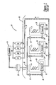
- Figure 1 is a system block diagram of a prior art refrigeration system configuration
- FIG. 2 is a system block diagram of a condensing unit or cooling system in accordance with the present invention
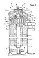
- Figure 3 is a cross-sectional view of an embodiment of a pulse-width modulated compressor shown in the loaded state
- Figure 4 is a cross-sectional view of the compressor of Figure 3, shown in the unloaded state;
- Figure 5 is a vertical cross-sectional view of the piston assembly shown in Figures 3 and 4;
- Figure 6 is a cross-sectional top view of the non-orbiting scroll shown in Figures 3 and 4;
- Figure 7 is another embodiment of a condensing unit or cooling system in accordance with the present invention.
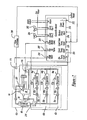
- Figure 8 is a schematic view illustrating the controller shown in Figure 7;
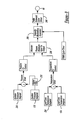
- FIG. 9 is a flow diagram for the control system of the present invention.
- Figure 10 is a plan view of the controls for the controller shown in Figures 7 and 8;
- Figure 11 is a schematic view illustrating a case controller and system controller in accordance with the present invention.
- Figure 12 is a system block diagram of a condensing unit or cooling system in accordance with an alternative embodiment of the present invention.
- Refrigeration system 10 includes a plurality of compressors 12 and a condenser 14 located remote from a plurality of refrigeration cases 16.
- compressors 12 are configured in a parallel bank located in a machine room or on a roof 18 of a building.
- Compressors 12 supply condenser 14 that may be air cooled or water cooled.
- Condenser 14 supplies liquid refrigerant to a receiver 20.
- Receiver 20 in turn, supplies refrigerant to the individual refrigeration cases 16, which are connected in parallel, as illustrated.
- a liquid line solenoid valve 22 is used to regulate the flow of refrigerant to the associated evaporator 24.
- the refrigerant is supplied to evaporator 24 through a suitable expansion device such as expansion valve 26.
- Expansion valve 26 provides a restricted orifice that causes the liquid refrigerant to atomize into liquid droplets that are introduced into the inlet side of evaporator 24.
- Evaporator 24, located within refrigerant case 16, extracts heat from case 16 and its contents by vaporization of the liquid droplets into a gas. Compressors 12 extract this gas by suction and compress the gas. The high-temperature compressed gas is then cooled by condenser 14 back into the liquid state and returned to receiver 20, whereupon the cycle continues.
- compressors 12 may be switched on and off individually or in groups as required.
- a liquid line 28 and a suction line 30 may each need to be quite lengthy (e.g., up to 150 feet) to span the distance from refrigeration cases 16 to a machine room or roof 18.
- Cooling system 40 includes a refrigeration case 42, a compressor 44, a condenser 46, a first expansion valve 48, an economizer 50, a second expansion valve 52 and an evaporator 54. While cooling system 40 is being illustrated in conjunction with refrigeration case 42, it is within the scope of the present invention to use cooling system 40 in conjunction with other cooling devices if desired.
- Condenser 46 and compressor 44 are both disposed within case 42 or attached thereto.
- Evaporator 54 and the associated expansion valves 48 and 52 are likewise disposed within case 42.
- Condenser 46 includes a heat removal mechanism 56 by which heat is transferred to ambient.
- Heat removal mechanism 56 can be a water jacket connected to suitable plumbing for carrying waste heat to a water cooling tower located on the building roof or elsewhere exterior to the building. Alternately, heat removal mechanism 56 can be a forced-air cooling system or a passive convection-air cooling system.
- Cooling system 40 also uses a liquid-line shut off valve 58 for controlling the flow of refrigerant to evaporator 54. Valve 58 communicates with control sensors to supply the refrigerant to evaporator 54 on demand.
- Cooling system 240 includes a series of refrigeration cases 242a, 242b and 242c, as well as a group of compressors 244a, 244b, 244c and 244d.
- the group of compressors 244a-d includes at least one pulse-width modulated compressor 244d.
- Cooling system 240 is a split system wherein compressors 244a-d are on a roof or in a machine room 18 of a building, while refrigeration cases 242a-c are disposed in a retail area of the building.
- cooling system 240 In machine room 18 along with compressors 244a-d are a condenser 246, a first expansion valve 248, and an economizer 250.
- cooling system 240 includes a second expansion valve 252 and an evaporator 254. While cooling system 240 is illustrated in Figure 12 in conjunction with refrigeration cases 242a-c, it is within the scope of the present invention to use cooling system 240 in conjunction with other cooling devices it desired.
- Condenser 246 includes a heat removal mechanism 256 by which heat is transferred to ambient.
- Heat removal mechanism 256 can be a water jacket connected to suitable plumbing for carrying waste heat to a water cooling tower located on the building roof or elsewhere exterior to the building.
- heat removal mechanism 256 can be a forced-air cooling system or a passive convection-air cooling system.
- Cooling system 240 also uses a liquid-lined shut-off valve 258 for controlling the flow of refrigerant to each evaporator 254. Valve 258 communicates with control sensors to supply the refrigerant to evaporator 254 on demand.
- Cooling system 240 like cooling system 40, employs the compressor controller 60 to supply a pulse-width modulated control signal on a capacity signal line 62 to a capacity solenoid valve 64 for compressor 244d. Again, controller 60 adjusts the pulse width of the control signal for valve 64 using an algorithm described below. While only one pulse-width modulated compressor 244d is shown in Figure 12, more compressors can include a capacity solenoid valve 64 for pulse-width modulation by controller 60. Further, while not shown in Figure 12, controller 60 may also supply a pulse-width modulated vapor-injection signal on an injection signal line to an injection solenoid valve for any of compressors 244a-d. Controller 60 adjusts the pulse width of the control signal for the injection solenoid valve using an algorithm described below.
- Cooling system 40 employs a condensing unit or system controller 60 that supplies a pulse-width modulated control signal on a capacity signal line 62 to a capacity solenoid valve 64 for compressor 44. Controller 60 adjusts the pulse width of the control signal for valve 64 using an algorithm described below. Controller 60 also supplies a pulse-width modulated vapor-injection signal on an injection signal line 66 to an injection solenoid valve 68 for compressor 44. Controller 60 adjusts the pulse width of the control signal for valve 68 using an algorithm described below.
- Scroll compressor 44 comprises an outer shell 70 within which is disposed a driving motor including a stator 72 and a rotor 74, a crankshaft 76 to which rotor 74 is secured, an upper bearing housing 78 and a lower bearing housing 80 for rotatably supporting crankshaft 76 and a compressor assembly 82.
- a driving motor including a stator 72 and a rotor 74, a crankshaft 76 to which rotor 74 is secured, an upper bearing housing 78 and a lower bearing housing 80 for rotatably supporting crankshaft 76 and a compressor assembly 82.
- Compressor assembly 82 includes an orbiting scroll member 84 supported on upper bearing housing 78 and drivingly connected to crankshaft 76 via a crankpin 86 and a drive bushing 88.
- a non-orbiting scroll member 90 is positioned in meshing engagement with orbiting scroll member 84 and is axially movably secured to upper bearing housing 78 by means of a plurality of bolts (not shown) and associated sleeve members (not shown).
- An Oldham coupling 92 cooperates with scroll members 84 and 90 to prevent relative rotation therebetween.
- a partition plate 94 is provided adjacent the upper end of shell 70 and serves to divide the interior of shell 70 into a discharge chamber 96 at the upper end thereof and a suction chamber 98 at the lower end thereof.
- suction gas is drawn into suction chamber 98 of shell 70 via a suction fitting 100. From suction chamber 98, suction gas is sucked into compressor 82 through an inlet 102 provided in non-orbiting scroll member 90.
- the intermeshing scroll wraps provided on scroll members 84 and 90 define moving pockets of gas that progressively decrease in size as they move radially inwardly as a result of the orbiting motion of scroll member 84, thus compressing the suction gas entering via inlet 102.
- the compressed gas is then discharged into discharge chamber 96 via a discharge port 104 provided in non-orbiting scroll member 90 and a passage 106 formed in partition 94.
- a pressure responsive discharge valve 108 is preferably seated within discharge port 104.
- Non-orbiting scroll member 90 is also provided with an annular recess 110 formed in the upper surface thereof.
- a floating seal 112 is disposed within recess 110 and is biased by intermediate pressurized gas against partition 94 to seal suction chamber 98 from discharge chamber 96.
- a passage 114 extends through non-orbiting scroll member 90 to supply the intermediate pressurized gas to recess 110.
- a capacity control system 120 is shown in association with compressor 44.
- Control system 120 includes a discharge fitting 122, a piston 124, a shell fitting 126 and solenoid valve 64.
- Discharge fitting 122 is threadingly received or otherwise secured within discharge port 104.
- Discharge fitting 122 defines an internal cavity 130 and a plurality of discharge passages 132.
- Discharge valve 108 is disposed below fitting 122 and below cavity 130.
- Discharge fitting 122 defines an annular flange 134. Seated against flange 134 is a lip seal 136 and a floating retainer 138. Piston 124 is press fit or otherwise secured to discharge fitting 122 and piston 124 defines an annular flange 140 that sandwiches seal 136 and retainer 138 between flange 140 and flange 134. Discharge fitting 122 defines a passageway 142 and an orifice 144 that extends through discharge fitting 122 to fluidically connect discharge chamber 96 with a pressure chamber 146 defined by discharge fitting 122, piston 124, seal 136, retainer 138 and shell 70.
- Shell fitting 126 is secured within a bore defined by shell 70 and slidingly receives the assembly of discharge fitting 122, piston 124, seal 136 and retainer 138.
- Pressure chamber 146 is fluidically connected to solenoid 64 by a tube 148 and with suction fitting 100 and thus suction chamber 98 through a tube 150.
- the combination of piston 124, seal 136 and floating retainer 138 provides a self-centering sealing system to provide accurate alignment with the internal bore of shell fitting 126.
- Seal 136 and floating retainer 138 include sufficient radial compliance such that any misalignment between the internal bore of fitting 126 and the internal bore of discharge port 104 within which discharge fitting 122 is secured is accommodated by seal 136 and floating retainer 138.
- solenoid valve 64 is deactivated (or it is activated) by controller 60 to block fluid flow between tube 148 and tube 150.
- chamber 146 is in communication with discharge chamber 96 through passageway 142 and orifice 144.
- the pressurized fluid at discharge pressure within chambers 96 and 146 will act against opposite sides of piston 124, thus allowing for the normal biasing of non-orbiting scroll member 90 towards orbiting scroll member 84 to sealingly engage the axial ends of each scroll member with the respective end plate of the opposite scroll member.
- the axial sealing of the two scroll members 84 and 90 causes compressor 44 to operate at 100% capacity.
- solenoid valve 64 In order to unload compressor 44, solenoid valve 64 will be actuated (or it will be deactuated) by controller 60 to the position shown in Figure 4. In this position, suction chamber 98 is in direct communication with chamber 146 through suction fitting 100, tube 150, solenoid valve 64 and tube 148. With the discharge pressure pressurized fluid released to suction from chamber 146, the pressure difference on opposite sides of piston 124 will move non-orbiting scroll member 90 upward to separate the axial end of the tips of each scroll member with its respective end plate and the higher pressurized pockets will bleed to the lower pressurized pockets and eventually to suction chamber 98. Orifice 144 is incorporated to control the flow of discharge gas between discharge chamber 96 and chamber 146.
- solenoid valve 64 When compression of the suction gas is to be resumed, solenoid valve 64 will be deactuated (or it will be actuated) to again block fluid flow between tubes 148 and 150 allowing chamber 146 to be pressurized by discharge chamber 96 through passageway 142 and orifice 144.
- Compressor 44 includes the capability of having fluid injected into the intermediate pressurized moving chambers at a point intermediate suction chamber 98 and discharge chamber 96.
- a fluid-injection fitting 160 extends through shell 70 and is fluidically connected to an injection tube 162, which is in turn fluidically connected to an injection fitting 164 secured to non-orbiting scroll member 90.
- Non-orbiting scroll member 90 defines a pair of radial passages 166, each of which extend between injection fitting 164 and a pair of axial passages 168.
- Axial passages 168 are open to the moving chambers on opposite sides of non-orbiting scroll member 90 of compressor assembly 82 to inject the fluid into these moving chambers as required by controller 60.
- FIG. 2 illustrates vapor injection system 158, which provides the fluid for the fluid injection system of compressor 44.
- Compressor 44 is shown in a cooling system including condenser 46, first expansion valve or throttle 48, economizer 50, a second expansion valve or throttle 52, an evaporator 54 and a series of piping interconnecting the components as shown in Figure 2.
- Compressor 44 is operated by the motor to compress the refrigerant gas.
- the compressed gas is then liquefied by condenser 46.
- the economizer 50 can be a flash-tank or heat-exchanger type economizer.
- the liquefied refrigerant passes through expansion valve 48 to flash-tank type economizer 50 where it is separated into gas and liquid.
- the gaseous refrigerant further passes through additional piping to be introduced into compressor 44 through fitting 160.
- the remaining liquid refrigerant further expands in expansion valve 52, is then vaporized in evaporator 54 and is again taken into compressor 44.
- the incorporation of flash-tank economizer 50 and the remainder of the vapor injection system allows the capacity of the compressor 44 to increase above the fixed capacity of compressor 44.
- the capacity of the compressor 44 can be increased by approximately 30% to provide a compressor with 130% of its capacity.
- solenoid valve 68 is positioned between economizer 50 and fitting 160.
- the increased capacity of compressor 44 can be controlled by controller 60, which operates solenoid valve 68 either in a pulse width injection or continuous injection mode.
- Solenoid valve 68 when operated in a pulse width modulation mode, in combination with capacity control system 120 of compressor 44 allows the capacity of compressor 44 to be positioned anywhere between 0% and 130% of its fixed capacity to accommodate faster load pull down.
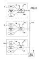
- a single compressor 44 and condenser 46 can service several distributed refrigeration cases or several distributed cooling units in a heating and cooling (HVAC) system.
- HVAC heating and cooling
- the refrigeration cases or cooling system housings are shown as dashed boxes designated 42a, 42b and 42c.
- compressor 44 and condenser 46 may be disposed within or attached to one of the refrigeration cases or housings, such as refrigerant case or housing 42a or disposed remotely, such as in a split system as shown in Figure 12, wherein the compressor 46 and condenser 44 are in a machine room or in a building roof 18.
- Each refrigeration case or housing has its own evaporator and associated second expansion valve as illustrated at 54 (a, b, c) and 52 (a, b, c) as well as a liquid line shut off valve 58 (a, b, c) and a thermostat 172 (a, b, c), which controls a respective liquid line shut off valve 58 (a, b, c).
- one of the refrigeration cases or housings typically the lowest temperature case or housing, may have a temperature sensor 174 as illustrated for refrigeration case or housing 42a. When temperature sensor 174 is included, it supplies output information to controller 60 as described below.
- a pressure sensor 176 can be included which monitors the pressure of the refrigerant entering suction fitting 100. Pressure sensor 176 supplies this information to controller 60 as described below.
- each evaporator 54 can have its own case controller 300 to perform defrost, fan, and electronic expansion valve control based on the case temperature and case outlet pressure, as shown in Figures 2, 7 and 11.
- a group of refrigeration cases 42a, 42b, 42c each included a case controller 300a, 300b, 300c, respectively.
- Temperature sensors 174a, 174b and 174c and pressure sensors 176a, 176b and 176c provide temperature and case outlet pressure measurements to the respective case controllers 300a, 300b and 300c.
- the case controllers 300a, 300b and 300c are connected via a digital two-way communication path 310 to the system controller 60, whereby temperature and pressure sensor values and case demand loading state (1 or 0) can be provided to system controller 60 by case controllers 300a, 300b and 300c. Further, each case controller 300a, 300b and 300c performs defrost, electronic expansion valve, and fan control locally based on the receive temperature and pressure sensor values.
- the multiple case or multiple cooling unit embodiment of Figure 7 shows how a single compressor 44 can be pulse-width modulated for capacity control and vapor injection by controller 60 to supply the instantaneous demand for cooling.
- Temperature sensor 174 and/or pressure sensor 176 provide an indication of the load on the system.
- Controller 60 adjusts the pulse width modulation of both the capacity control system 120 and the vapor injection system to modulate the compressor between its high capacity and low capacity states to meet the instantaneous demand for refrigerant as described below.
- Controller 60 is capable of controlling the capacity of compressor 44 by using pulse width modulation of solenoid valve 64.
- the capacity of compressor 44 can be controlled from 0% to 100% but for this embodiment, the capacity is modulated from 10% to 100% by pulse width modulation operation.
- the capacity of compressor 44 can be increased anywhere from 100% to approximately 130% by pulse width modulation of solenoid valve 68, which controls the vapor injection system of the present invention. It is also possible for controller 60 to operate solenoid valve 68 in an on/off manner if desired.
- the operational characteristics and algorithms incorporated into controller 60 are detailed below.
- Controller 60 is capable of controlling either single-evaporator (Figure 2) or multi-evaporator ( Figure 7) refrigeration systems.
- the multi-evaporator systems could have evaporators at similar temperatures or at mixed temperatures by employing electronic pressure regulators in the higher temperature evaporators.
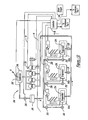
- Controller 60 controls an alarm output 200 that will remain on during any alarm condition. Alarm output 200 will reset itself when all alarm conditions are gone.
- Controller 60 controls the operation of a first condenser fan 202 and a second condenser fan 204.
- Cooling system 40 includes two condenser fan motors and fans for condenser 46.
- Controller 60 controls the operation of the motor for compressor 44 as shown at 206, it controls the operation of vapor injection solenoid valve 68 as shown at 208 and it controls the operation of capacity control solenoid valve 64 as shown at 210.
- controller 60 Various inputs are provided to controller 60. These inputs include control power at 212, an optional suction pressure input from pressure sensor 176 at 214, an optional load case temperature input from temperature sensor 174 at 216, the temperature of refrigerant at the mid-coil or the coil return of condenser 46 from a temperature sensor 218 at 220 and the temperature of the discharge gas of compressor 44 from a temperature sensor 222 at 224.
- controller 60 can control the capacity of compressor 44 based on either case air temperature, compressor suction pressure, or both as detailed below. Controller 60 and the various terminal blocks are housed in an enclosure (not shown) suitable for mounting on cooling system 40.
- cooling system 40 also includes a low pressure cutout electromechanical switch to stop compressor 44 at very low suction pressure for vacuum protection; and a high head pressure cutout electromechanical switch to stop compressor 44 at very high discharge pressure, if such protection is required.
- each evaporator 54 (a, b, c) has associated with it their own liquid line solenoid valve 58 (a, b, c), their own temperature sensors 172 (a, b, c) and their own thermostatic expansion valve 52 (a, b, c). None of these valves or sensors are in communication with controller 60. The only communication with controller 60 is through lead case temperature sensor 174 and/or suction pressure sensor 176.
- controller 60 is capable of being switched between refrigerants, including, but not limited to, R-404A, R-407C, R-22, R-134a and R-410A as detailed below.
- Controller 60 modulates the capacity of compressor 44 through pulse width modulation control of solenoid valve 64 and/or solenoid valve 68.
- Controller 60 can be set to use suction pressure control using sensor 176, lead case temperature control using sensor 174 or a combination of lead case temperature control with suction control backup using sensors 174 and 176. Each will be described in turn.
- Suction Pressure Control During suction pressure control, compressor 44 will be operated with the loading time adjusted to maintain an average suction pressure at a suction pressure set point 230. Determining the average suction pressure will be done by taking many samples of suction pressure during each load/unload cycle time of compressor 44 and then filtering this suction pressure data using a digital filter 232.
- the digital filter will produce a useful average pressure for control purposes by removing almost all of the pressure fluctuations caused by the loading and unloading of compressor 44.
- the sampling rate of the digital filter will be inversely proportional to the pulse-width-modulation (PWM) cycle time so that regardless of the PWM cycle time selected, the digital filter will operate with twenty samples during each PWM cycle.
- PWM pulse-width-modulation
- the filtering thus achieved will have appropriate timing to match the PWM cycle time selected.
- Control of the suction pressure is by PID algorithm.
- the suction pressure set point is settable at controller 60 as described below.
- the signal from suction pressure sensor 176 is first routed through the digital filter and then to the suction pressure PID algorithm. If suction pressure control is chosen, then the lead case temperature PID algorithm is ignored.
- Lead Case Temperature Control During lead case temperature control, compressor 44 will be operated with the loading duty cycle percentage adjusted to maintain the temperature of air in the chosen lead case at a lead case temperature set point 234. Control of this lead case temperature will be by PID algorithm.
- the lead case temperature set point will be settable on controller 60 as described below. The signal from temperature sensor 174 will go directly to the lead case temperature PID algorithm. If lead case temperature control is chosen, the suction pressure PID algorithm will be ignored.
- Combination Control During combination control, compressor 44 will be operated to achieve both suction pressure set point 230 and lead case temperature set point 234. The capacity of compressor 44 will be increased until both of these set points are satisfied.
- the combination control is accomplished by allowing both suction pressure PID control and lead case temperature PID control to function simultaneously. Controller 60 gives dominance to whichever PID control calls for the lowest compressor capacity. The determination of which one controls will be recalculated during each unloaded cycle for compressor 44.
- the preferred intent of this combination control is that lead case temperature will be the dominant control most of the time, so it must require the lesser compressor capacity.
- the lead case temperature set point will usually be set to a slightly higher refrigeration temperature than the suction pressure set point by itself would achieve.
- the outputs of the two PID control functions (one for suction pressure and one for lead case temperature) will be combined in a selector 236 that will pass on the lesser of the two.
- the selector will supply the signal to a capacity modulation generator 238.
- the capacity modulation generator generates the timing of PWM solenoid valve 64 which is provided to a solenoid driver 240.
- the reason for preferring dominance of the lead case temperature is that if the suction pressure set point were set to achieve a lower temperature than the lead case temperature set point, then the suction pressure control would dominate and the temperature of the lead case would be held at a temperature lower than the lead case temperature set point. Such settings essentially disable the usefulness of the lead case temperature measurement.
- suction pressure control during a dominant lead temperature control is useful during defrosts of the lead case because the suction pressure is lower than the lead case temperature during defrost.
- the pressure of suction pressure sensor 176 enables better condenser control and better protection against short cycling the compressor motor when suction pressure goes too low.
- the combination control mode will have no inner loop and no outer loop.
- the two PID control paths are equals, both active, with selector 236 determining which has controlling effect at the moment.
- the output of the selector algorithm of selector 236 will be converted to a duty cycle value of a repeating pulse by capacity modulation generator 238.
- the output of capacity modulation generator 238 will control solenoid valve 64 of compressor 44. More capacity will cause solenoid valve 64 to be energized (or de-energized) during a smaller proportion of the cycle time to increase compressor 44's capacity.
- e(t) is the error signal between the sensed value and the set point
- K p is the proportional constant
- K d is the derivative constant
- K i / ⁇ is the integral constant.
- the two PID (Proportional-Integral-Derivative) algorithms may be simplified to PI (Proportional-Integral) algorithms with no derivative function. In relation to the output equation above, the proportional and integral constants are divided by 100 to arrive at P and I as used here.
- PID (or PI) constants for the suction pressure control will be adjustable and they will have default values. There will also be minimum and maximum values, beyond which they cannot be set.
- These PI constants for the lead case temperature control will be adjustable and they will have default values. There will also be minimum and maximum values, beyond which they cannot be set.
- the PWM maximum cycle time will be user selectable as described below. Preferably the default value will be 20 seconds, the minimum value will be 10 seconds and the maximum value will be 60 seconds.
- a low compressor capacity limit is also provided. Even though the capacity of compressor 44 can be reduced to 0%, controller 60 will turn off the motor of compressor 44 if the required compressor capacity value goes below 10%. Restarting of the motor will be governed by the capacity requirement rising to 10% or more and by the motor start logic.
- Control for low capacity with short PWM cycle time is also provided.
- the loaded time for compressor 44 will be controlled to be no less than two seconds. For a PWM maximum cycle time setting of twenty seconds (the default value) or more, this condition is met by the minimum loaded duty cycle of 10%. For a PWM maximum cycle time setting of less than twenty seconds (ten-twenty seconds), the PWM cycle time will be increased when the capacity is at a low value so that the minimum loaded time condition of two seconds is maintained. If the PWM maximum cycle time is set to ten seconds, then while PWM is 20% or more, the minimum loaded time of two seconds is satisfied. If the capacity decreased to 15%, then to maintain the minimum loaded time of two seconds, the PWM cycle time will increase automatically to thirteen and one-third seconds.
- Controller 60 is programmed to operate injection solenoid valve 68. This will increase the capacity of compressor 44 to approximately 130%. Controller 60 will only operate solenoid valve 68 when capacity solenoid valve 64 is de-energized. Thus, before vapor injection by controller 60 can proceed, the capacity of compressor 44 must be at 100%. Controller 60 will then operate solenoid valve 68 using pulse width modulation to increase the capacity of compressor 44 from 100% up to approximately 130% depending on the requirements determined by controller 60.
- Delay - Controller 60 includes motor start logic which prohibits the compressor motor from being started until after an appropriate time delay.
- the time delay will begin at the most recent moment that the compressor motor was stopped.
- the compressor motor will have a start delay of two minutes and this delay time is not adjustable. This prevents more than thirty motor starts in any given hour.
- Start Unloaded - Controller 60 includes additional motor start logic which unloads compressor 44 at the time of starting by energizing (or de-energizing) solenoid valve 64.
- the unloaded starting of the motor will reduce motor inrush current and enable more motor starts without excessive wear on the motor contactor.
- solenoid valve 64 will be energized (or de-energized) one second before energizing the motor contactor to unload compressor 44 and it will remain energized (or de-energized) for three seconds after the motor starts keeping compressor 44 unloaded. After this unloaded running, control of solenoid valve 64 is returned to the normal PID control algorithms assuming controller 60 is operating.
- controller 60 If controller 60 has failed or is not powered, then application of power to the rest of cooling system 40 will cause all motors and vapor injection to run without delay.
- the PWM output will be off and compressor 44 will operate at 100% capacity with the vapor injection increasing the capacity to approximately 130%.
- Controller 60 may include suction pressure sensor 176.
- suction pressure sensor 176 When sensor 176 is included, pump down when an individual case 42 goes into defrost (stopping refrigerant flow) will generally not occur because the pressure control algorithm will reduce compressor capacity to maintain the suction pressure at set point 230. However, suction pressure sensor 176 is positioned in front of digital filter 232 and thus pressure sensor 176 can monitor excessively low suction pressure. Preferably, if instantaneous suction pressure goes below five PSIG, the compressor motor will be stopped immediately, and restart logic will be invoked. Preferably, the electromechanical low pressure cutout switch should be set to zero PSIG. In this manner, it will prevent vacuum but it will also allow suction pressure sensor 176 to prevent low pressure conditions. The electromechanical switch then becomes a backup control. When suction pressure sensor 176 is not included with controller 60, then controller 60 cannot prevent pump down. The external electromechanical low pressure cutout switch must control compressor 44 under such conditions. Restart logic (the delay) within controller 60 cannot be invoked.
- cooling system 40 includes temperature sensor 222 which monitors the discharge temperature for compressor 44.
- Controller 60 includes two set points for the discharge gas temperature of compressor 44.
- VHDTC Very High Discharge Temperature Condition
- HDTC High Discharge Temperature Condition
- the compressor motor will be turned off.
- Vapor Injection During High Discharge Temperature If the compressor motor is running and the HDTC is true but the VHDTC is false, the capacity for compressor 44 will be forced to 100% by ending the pulse width modulation for solenoid valve 64 and vapor injection solenoid 68 will be energized (or de-energized) to provide full vapor injection. Then, if the compressor motor is running and the HDTC returns to false (and the VHDTC remains false), the compressor capacity will return to normal control and vapor injection solenoid 68 will be de-energized (or energized) to end vapor injection. The ending of vapor injection assumes the compressor capacity is below 100%.
- Controller 60 allows for an automatic restart but this automatic restart may be locked out, requiring a manual reset as detailed below.
- controller 60 keeps a count of these High Discharge Temperature Shutdown Events (HDTSE).
- HDTSE High Discharge Temperature Shutdown Events
- the HDTSE counter will be at zero until a HDTSE occurs.
- the counter will increment by one each time a HDTSE occurs at the time the condition is detected.
- a thirty minute high discharge temperature restart delay timer will be started each time a HDTSE occurs.
- Manual Reset The counter for the high discharge temperature events may be reset to zero any time, even if its count is less than four. Manual reset of the counter will clear both the count and any time remaining on the thirty minute delay timer. After a manual reset, the motor will restart only if (or after) the temperature of the discharge gas has decreased as sensed by sensor 222. This arrangement will allow factory test of the high temperature shutdown feature without undue time loss for delays and without wasting allowed automatic restarts.
- controller 60 will include a separate push-button 250 ( Figure 10) for Manual Reset and push-button 250 must be pressed and held for two seconds to achieve manual restart. A yellow LED 252 beside push-button 250 indicates the need for a manual restart. LED 252 will be turned on when E14 is being displayed and LED 252 will turn off when the manual restart process has begun.
- Condenser Fan Control Algorithm - controller 60 operates two condenser fans 202 and 204.
- Fans 202 and 204 will be operated in a lead and lag fashion, with control based primarily on condensing temperature and partially upon the running capacity of compressor 44 and partially upon Saturated Suction Temperature (SST).
- SST Saturated Suction Temperature
- the condenser fan control algorithm will use the following six test control fans 202 and 204. These values are chosen to preferably maintain at least seventy-five PSI pressure difference across compressor 44 to ensure good performance even at very low outdoor ambient and condensing temperatures.
- the condenser control algorithms do not have adjustable set points other than the type of refrigerant. In the tests below, SCT is Saturated Condenser Temperature, SST is Saturated Suction Temperature and CapC is the capacity of the compressor within limits for condenser 46.
- Condenser Fan Alternation which condenser fan leads and which one lags in the above described control scheme is alternated by a fan alternation timer.
- the lead/lag fan is alternated about once every twenty hours. If at the time for alternation and only one fan is on, the alternation will not occur.
- the fan alternation timer will wait until the next time both fans are on or both fans are off to make the change. However, if the alternation favorable condition (both on or off) does not occur after a long period of time, then the change of lead and lag fans will be forced to happen.
- an alternation suspend timer will run for five hours before forcing the change. The timer is started by timeout of the fan alternation timer (twenty hours) and it is reset by successful alternation of lead and lag fans. This alternation method reduces wear stress by evening out run time for each fan.
- Normal condenser fan operation depends upon signals from two sensors. Normal condenser fan operation will be suspended and a backup control algorithm will take over if failure of a sensor used by the condenser control is detected. When there is a sensor failure affecting the condenser control, the lead fan will be on any time the compressor is running. The lag fan will turn on any time the compressor capacity exceeds 35% and turn off when the compressor capacity is below 25%.
- Suction Pressure Sensor Failure If suction pressure set point 230 is not 99 and suction pressure sensor 176 appears to controller 60 to be disconnected, this will constitute a detection of a failed sensor 176 and an error code E01 will be displayed and alarm 200 will be turned on.
- the compressor capacity will be set at 100% and vapor injection solenoid 68 will be energized (or de-energized) to increase the capacity above 100%. Compressor 44 will remain in this state until the failed sensor condition is no longer detected. If suction pressure set point 230 is set to 99, this signals controller 60 that suction pressure control is not to be used and alarm 200 will not be turned on.
- Lead Case Temperature Sensor Failure If lead case temperature set point 234 is not 99 and lead case temperature sensor 174 appears to controller 60 to be either disconnected or shortened out, this will constitute a detection of a failed sensor 174 and an error code E02 will be displayed and alarm 200 will be turned on.
- the compressor capacity will be set at 100% and vapor injection solenoid 68 will be energized (or de-energized) to increase the capacity above 100%. Compressor 44 will remain in this state until the failed sensor condition is no longer detected. If lead case temperature set point 234 is set to 99, this signals controller 60 that lead case temperature control is not to be used and alarm 200 will not be turned on.
- Condenser Temperature Sensor Failure If condenser temperature sensor 218 appears to controller 60 to be disconnected or shorted out, this will constitute a detection of a failed sensor 218 and an error code E03 will be displayed and alarm 200 will be turned on.
- the display will comprise three seven segment digits 254, 256 and 258; four push-buttons 250, 260, 262 and 264; and seventeen point lights 252 and 266-296, all Light Emitting Diodes as shown in Figure 10.
- Digits - Controller 60 displays the various set points and error codes discussed above using "seven segment" digits 254, 256 and 258.
- the illuminated part of digits 254-258 is preferably three-tenths of an inch high.
- the various error codes discussed above (E01 through E14) will be indicated on the display briefly along with the operating values. This display of error codes and values will continue to repeat if alarm 200 is turned on. Preferably, if there is one alarm condition, the error code will be shown for one-half second and the selected operating value will be shown for 1.95 seconds. If there are multiple alarm conditions, they will be shown in numerical order for 0.45 seconds each with the selected operating valve being shown for two seconds each. Each alarm code display time will be surrounded by a blank display for one-half second. This will achieve a flash effect to call attention to the alarm.
- LED Point Lights
- the seventeen point lights are either green, red or yellow in color. Each output will have a point light associated with it. Green point lights indicate that the item is display-only. Red point lights indicate that the item has a set point that can be changed. Yellow lights indicate manual mode and alarm.
- LED 252 is a yellow point light which indicates manual reset of the counter for auto restarts must be manually set.
- LED 266 is a red point light which indicates a combination control of suction pressure and lead case temperature control is being used.
- LED 268 is a red point light which indicates that LEAD case temperature control is being used.
- LED 270 is a red point light that indicates that suction pressure control is being used. (Only one of LEDs 266-270 will be lit at one time).
- LED 272 is a green point light which indicates that the display is showing the suction pressure directly from suction pressure sensor 176.
- LED 274 is a red point light which indicates that the display is showing the average suction pressure from digital filter 232.
- LED 276 is a red point light which indicates that the display is showing the calculated saturation temperature (SST) of the refrigerant.
- LED 278 is a red point light which indicates that the display is showing the lead case temperature.
- LED 280 is a green point light which indicates that the display is showing the discharge temperature based on sensor 222.
- LED 282 is a yellow point light which indicates that the display is showing the current compressor capacity in the manual mode.
- LED 284 is a red point light which indicates that the display is showing the current compressor capacity in the automatic mode.
- LED 286 is a red point light which indicates the display is showing the total time for one PWM cycle of solenoid valve 64.
- LEDS 288-294 are each red point lights which indicate that the display is showing the four constants detailed above under "Compressor Capacity Control Algorithms”.
- LED 296 is a red point light which indicates that the display is showing the type of refrigerant being used.
- buttons 260-264 can be changed by operating push-buttons 260-264.
- the same push-buttons which select the display of operating values (262 and 264) will also select the underlying set points. Pushing these buttons will select the various set points and which set point is being displayed will be indicated by LEDS 272-296. The displayed value will be shown on digits 254-258.
- pressing and holding push-button 260 will then allow push-buttons 262 and 264 to decrease and increase, respectively, the value of the set point. If there is no associated set point with the operating value being displayed, then pushing push-button 260 will have no effect on buttons 262 and 264. All set points are maintained while power is off.
- the adjustable set points include Suction Pressure (LED 274), SST (LED 276), Lead Case Temperature (LED 278), Compressor Capacity (LEDs 282 and 284), PWM Cycle Time (LED 286), the four PID constants (LEDs 288-294) and the refrigerant type (LED 296).
- Suction Pressure This is the target average suction pressure to be achieved by the compressor. Setting this to 99 will disable the suction pressure control mode (LED 268 will lite) and controller 60 will assume pressure sensor 176 is not connected. Suction Pressure and SST are the views of the same set point assuming one adjusts the other.
- Lead Case Temperature This is the set point for lead case temperature. Setting it to 99 will disable the lead case temperature control mode (LED 270 will lite) and controller 60 will assume temperature sensor 174 is not connected. Setting both suction pressure and lead case temperature to lower values than 99 will cause the combination control mode to be used (LED 266 will lite).
- Compressor Capacity This allows for the manual mode of compressor 44 to be set. Merely selecting this item (LED 284) with buttons 262 or 264 will leave the control automatic under PID and the display will show the operating value of compressor capacity. Pressing and holding push-button 260 while this is selected (LED 284) will lock controller 60 at the capacity last calculated by the PID control loops and manual control of capacity will begin (LED 282 will lite, LED 284 will be turned off). The manual capacity may then be charged using push-buttons 262 or 264. Selecting a different set point using push-buttons 262 and 264 after releasing push-button 260 after changing the manual capacity allows observing of the operating values while in the manual PWM mode. Selecting a different set point and then pressing push-button 260 puts controller 60 back into the automatic mode.
- PWM Cycle Time - This allows for the setting of the total time for one PWM cycle of capacity solenoid valve 64.
- Refrigerant - This allows for the setting of the type of refrigerant being used in the system.
- these choices are R-404A, R-407C, R-22, R-134a and R-140. These will be shown in the display as 404, 407, 22, 134 and 410, respectively. These settings allow for the proper conversion between pressure and temperature. Controller 60 will include all five refrigerant settings even if compressor 44 is not qualified initially for all five refrigerants.
- Display Digits 254-258 on controller 60 can indicate any one of several operating values.
- Push-buttons 262 and 264 are used to scroll through the various operating values.
- LED 2778 This LED indicates that the current air temperature in the lead case is being displayed. This reading comes directly from temperature sensor 174.
- Compressor Capacity (LED 284) - This LED indicates that the current compressor running capacity is being displayed. This value is calculated by controller 60 and is used to operate capacity modulation generator 238, solenoid driver 240 and solenoid 64.
- PWM Cycle Time (LED 286) - This LED indicates the current value for the PWM cycle time set point.
- controller 60 has a manual operating mode and an automatic operating mode.
- controller 60 In the automatic mode, controller 60 will operate with capacity solenoid valve 64 controlled by the PID control loops.
- compressor 44 In the manual mode, compressor 44 will run with a constant fixed capacity. The capacity is set on controller 60 as detailed above. The condenser fan control and the compressor protection schemes will continue to operate in the manual mode just as in the automatic mode. The manual mode is intended for test purposes. Controller 60 will begin its operation in the automatic mode after a reset.
Priority Applications (1)
| Application Number | Priority Date | Filing Date | Title |
|---|---|---|---|
| EP10013134.1A EP2284463B1 (fr) | 2001-03-16 | 2002-01-15 | Régulateur digital pour une unité de condensation avec compresseur à spirales |
Applications Claiming Priority (3)
| Application Number | Priority Date | Filing Date | Title |
|---|---|---|---|
| US811092 | 2001-03-16 | ||
| US09/811,092 US6601397B2 (en) | 2001-03-16 | 2001-03-16 | Digital scroll condensing unit controller |
| EP02250266A EP1241417B1 (fr) | 2001-03-16 | 2002-01-15 | Régulateur digital pour une unité de condensation avec compresseur à spirales |
Related Parent Applications (1)
| Application Number | Title | Priority Date | Filing Date |
|---|---|---|---|
| EP02250266A Division EP1241417B1 (fr) | 2001-03-16 | 2002-01-15 | Régulateur digital pour une unité de condensation avec compresseur à spirales |
Related Child Applications (2)
| Application Number | Title | Priority Date | Filing Date |
|---|---|---|---|
| EP10013134.1A Division EP2284463B1 (fr) | 2001-03-16 | 2002-01-15 | Régulateur digital pour une unité de condensation avec compresseur à spirales |
| EP10013134.1A Division-Into EP2284463B1 (fr) | 2001-03-16 | 2002-01-15 | Régulateur digital pour une unité de condensation avec compresseur à spirales |
Publications (3)
| Publication Number | Publication Date |
|---|---|
| EP1562011A2 true EP1562011A2 (fr) | 2005-08-10 |
| EP1562011A3 EP1562011A3 (fr) | 2009-06-24 |
| EP1562011B1 EP1562011B1 (fr) | 2015-04-15 |
Family
ID=25205532
Family Applications (3)
| Application Number | Title | Priority Date | Filing Date |
|---|---|---|---|
| EP10013134.1A Expired - Lifetime EP2284463B1 (fr) | 2001-03-16 | 2002-01-15 | Régulateur digital pour une unité de condensation avec compresseur à spirales |
| EP05006892.3A Expired - Lifetime EP1562011B1 (fr) | 2001-03-16 | 2002-01-15 | Régulateur digital pour une unité de condensation avec compresseur à spirales |
| EP02250266A Expired - Lifetime EP1241417B1 (fr) | 2001-03-16 | 2002-01-15 | Régulateur digital pour une unité de condensation avec compresseur à spirales |
Family Applications Before (1)
| Application Number | Title | Priority Date | Filing Date |
|---|---|---|---|
| EP10013134.1A Expired - Lifetime EP2284463B1 (fr) | 2001-03-16 | 2002-01-15 | Régulateur digital pour une unité de condensation avec compresseur à spirales |
Family Applications After (1)
| Application Number | Title | Priority Date | Filing Date |
|---|---|---|---|
| EP02250266A Expired - Lifetime EP1241417B1 (fr) | 2001-03-16 | 2002-01-15 | Régulateur digital pour une unité de condensation avec compresseur à spirales |
Country Status (10)
| Country | Link |
|---|---|
| US (2) | US6601397B2 (fr) |
| EP (3) | EP2284463B1 (fr) |
| KR (1) | KR100847265B1 (fr) |
| CN (4) | CN100451497C (fr) |
| AT (1) | ATE300711T1 (fr) |
| AU (1) | AU782942B2 (fr) |
| BR (1) | BRPI0105774B8 (fr) |
| DE (1) | DE60205149T2 (fr) |
| ES (1) | ES2542331T3 (fr) |
| TW (1) | TW539836B (fr) |
Cited By (1)
| Publication number | Priority date | Publication date | Assignee | Title |
|---|---|---|---|---|
| WO2011112495A3 (fr) * | 2010-03-08 | 2013-07-04 | Carrier Corporation | Appareils et procédés de distribution de fluide frigorigène pour un système de transport réfrigéré |
Families Citing this family (144)
| Publication number | Priority date | Publication date | Assignee | Title |
|---|---|---|---|---|
| US6505475B1 (en) | 1999-08-20 | 2003-01-14 | Hudson Technologies Inc. | Method and apparatus for measuring and improving efficiency in refrigeration systems |
| CN1184440C (zh) * | 2001-02-16 | 2005-01-12 | 三星电子株式会社 | 空调设备及其控制方法 |
| US6892546B2 (en) | 2001-05-03 | 2005-05-17 | Emerson Retail Services, Inc. | System for remote refrigeration monitoring and diagnostics |
| US6668240B2 (en) | 2001-05-03 | 2003-12-23 | Emerson Retail Services Inc. | Food quality and safety model for refrigerated food |
| US6658373B2 (en) * | 2001-05-11 | 2003-12-02 | Field Diagnostic Services, Inc. | Apparatus and method for detecting faults and providing diagnostics in vapor compression cycle equipment |
| US20060041335A9 (en) * | 2001-05-11 | 2006-02-23 | Rossi Todd M | Apparatus and method for servicing vapor compression cycle equipment |
| US6687122B2 (en) * | 2001-08-30 | 2004-02-03 | Sun Microsystems, Inc. | Multiple compressor refrigeration heat sink module for cooling electronic components |
| US6973793B2 (en) * | 2002-07-08 | 2005-12-13 | Field Diagnostic Services, Inc. | Estimating evaporator airflow in vapor compression cycle cooling equipment |
| US6672090B1 (en) * | 2002-07-15 | 2004-01-06 | Copeland Corporation | Refrigeration control |
| US6889173B2 (en) | 2002-10-31 | 2005-05-03 | Emerson Retail Services Inc. | System for monitoring optimal equipment operating parameters |
| US20040084175A1 (en) * | 2002-10-31 | 2004-05-06 | Bruce Kranz | Multi-zone temperature control system |
| KR20040050477A (ko) * | 2002-12-10 | 2004-06-16 | 엘지전자 주식회사 | 공기조화시스템 |
| JP4614642B2 (ja) * | 2003-08-29 | 2011-01-19 | 三洋電機株式会社 | 冷凍システム |
| KR100511288B1 (ko) * | 2003-11-14 | 2005-08-31 | 엘지전자 주식회사 | 4대의 압축기를 구비한 공기조화기의 실외기 |
| US7299649B2 (en) * | 2003-12-09 | 2007-11-27 | Emerson Climate Technologies, Inc. | Vapor injection system |
| CN1894763B (zh) | 2003-12-12 | 2010-12-08 | 山米奎普公司 | 用于在离子植入中延长设备正常运行时间的方法及装置 |
| JP2005257237A (ja) * | 2004-03-15 | 2005-09-22 | Sanyo Electric Co Ltd | 冷凍装置 |
| JP2005257236A (ja) * | 2004-03-15 | 2005-09-22 | Sanyo Electric Co Ltd | 冷凍装置 |
| KR100642709B1 (ko) * | 2004-03-19 | 2006-11-10 | 산요덴키가부시키가이샤 | 냉동 장치 |
| US7412842B2 (en) | 2004-04-27 | 2008-08-19 | Emerson Climate Technologies, Inc. | Compressor diagnostic and protection system |
| US7918655B2 (en) * | 2004-04-30 | 2011-04-05 | Computer Process Controls, Inc. | Fixed and variable compressor system capacity control |
| US6973797B2 (en) * | 2004-05-10 | 2005-12-13 | York International Corporation | Capacity control for economizer refrigeration systems |
| WO2005119141A1 (fr) * | 2004-05-28 | 2005-12-15 | York International Corporation | Systeme et procede de commande d'un circuit economiseur |
| US7275377B2 (en) | 2004-08-11 | 2007-10-02 | Lawrence Kates | Method and apparatus for monitoring refrigerant-cycle systems |
| US7143594B2 (en) * | 2004-08-26 | 2006-12-05 | Thermo King Corporation | Control method for operating a refrigeration system |
| US7481627B2 (en) * | 2004-08-30 | 2009-01-27 | Mat Industries Llc | Air compressor tools that communicate with an air compressor |
| US20060045749A1 (en) * | 2004-08-30 | 2006-03-02 | Powermate Corporation | Air compressor utilizing an electronic control system |
| US20060045751A1 (en) * | 2004-08-30 | 2006-03-02 | Powermate Corporation | Air compressor with variable speed motor |
| JP4268931B2 (ja) | 2004-12-30 | 2009-05-27 | 中山エンジニヤリング株式会社 | 冷蔵・冷凍設備及びその制御方法 |
| EP1851959B1 (fr) | 2005-02-21 | 2012-04-11 | Computer Process Controls, Inc. | Systeme de surveillance et de commande d'entreprise |
| JP2006275495A (ja) * | 2005-03-30 | 2006-10-12 | Sanyo Electric Co Ltd | 冷凍装置及び冷蔵庫 |
| US8418486B2 (en) * | 2005-04-08 | 2013-04-16 | Carrier Corporation | Refrigerant system with variable speed compressor and reheat function |
| JP3995007B2 (ja) * | 2005-05-30 | 2007-10-24 | ダイキン工業株式会社 | 調湿装置 |
| US7895854B2 (en) * | 2005-06-01 | 2011-03-01 | Hewlett-Packard Development Company, L.P. | Refrigeration system with parallel evaporators and variable speed compressor |
| KR20070004245A (ko) * | 2005-07-04 | 2007-01-09 | 삼성전자주식회사 | 압축기 |
| US7275385B2 (en) * | 2005-08-22 | 2007-10-02 | Emerson Climate Technologies, Inc. | Compressor with vapor injection system |
| US8037710B2 (en) * | 2005-08-22 | 2011-10-18 | Emerson Climate Technologies, Inc. | Compressor with vapor injection system |
| EP1938027A4 (fr) * | 2005-09-29 | 2011-12-21 | Carrier Corp | Appareil et systeme pour compresseur a refrigerant avec echangeur thermique a aspiration liquide |
| US7665315B2 (en) | 2005-10-21 | 2010-02-23 | Emerson Retail Services, Inc. | Proofing a refrigeration system operating state |
| US7752853B2 (en) | 2005-10-21 | 2010-07-13 | Emerson Retail Services, Inc. | Monitoring refrigerant in a refrigeration system |
| US7752854B2 (en) | 2005-10-21 | 2010-07-13 | Emerson Retail Services, Inc. | Monitoring a condenser in a refrigeration system |
| CN101297168A (zh) * | 2005-10-26 | 2008-10-29 | 开利公司 | 具有受脉宽调制的部件和可变速压缩机的制冷系统 |
| US7322806B2 (en) * | 2006-01-04 | 2008-01-29 | Scroll Technologies | Scroll compressor with externally installed thermostat |
| US20070251256A1 (en) * | 2006-03-20 | 2007-11-01 | Pham Hung M | Flash tank design and control for heat pumps |
| DK2008036T3 (en) * | 2006-03-27 | 2016-01-18 | Carrier Corp | Cooling system with parallel incremental economizer circuits using multi-stage compression |
| US7861546B2 (en) * | 2006-04-03 | 2011-01-04 | Computer Process Controls, Inc. | Refrigeration system capacity controller and method |
| US8590325B2 (en) | 2006-07-19 | 2013-11-26 | Emerson Climate Technologies, Inc. | Protection and diagnostic module for a refrigeration system |
| WO2008016347A1 (fr) * | 2006-08-01 | 2008-02-07 | Carrier Corporation | Conception modulaire de soupape de compresseur pour système de fluide frigorigène |
| US8240161B2 (en) * | 2006-08-08 | 2012-08-14 | Carrier Corporation | Suction valve pulse width modulation control based on compressor temperature |
| US20080216494A1 (en) * | 2006-09-07 | 2008-09-11 | Pham Hung M | Compressor data module |
| DE202006020240U1 (de) * | 2006-09-19 | 2008-02-07 | Ne-Ma S.P.A. Pressostati | Schaltungsanordnung für einen elektromotorisch angetriebenen Kolbenkompressor |
| US8024938B2 (en) * | 2006-11-14 | 2011-09-27 | Field Diagnostic Services, Inc. | Method for determining evaporator airflow verification |
| US20080196425A1 (en) * | 2006-11-14 | 2008-08-21 | Temple Keith A | Method for evaluating refrigeration cycle performance |
| EP2126490B1 (fr) * | 2007-02-14 | 2018-11-21 | Carrier Corporation | Optimisation de fonctionnement de système de refroidisseur aéro-réfrigéré |
| US20080264080A1 (en) * | 2007-04-24 | 2008-10-30 | Hunter Manufacturing Co. | Environmental control unit for harsh conditions |
| US8485789B2 (en) * | 2007-05-18 | 2013-07-16 | Emerson Climate Technologies, Inc. | Capacity modulated scroll compressor system and method |
| US20090037142A1 (en) | 2007-07-30 | 2009-02-05 | Lawrence Kates | Portable method and apparatus for monitoring refrigerant-cycle systems |
| US20090050219A1 (en) * | 2007-08-21 | 2009-02-26 | Briggs And Stratton Corporation | Fluid compressor and control device for the same |
| US8393169B2 (en) | 2007-09-19 | 2013-03-12 | Emerson Climate Technologies, Inc. | Refrigeration monitoring system and method |
| US20100199715A1 (en) * | 2007-09-24 | 2010-08-12 | Alexander Lifson | Refrigerant system with bypass line and dedicated economized flow compression chamber |
| US8160827B2 (en) | 2007-11-02 | 2012-04-17 | Emerson Climate Technologies, Inc. | Compressor sensor module |
| US9140728B2 (en) | 2007-11-02 | 2015-09-22 | Emerson Climate Technologies, Inc. | Compressor sensor module |
| JP4780479B2 (ja) | 2008-02-13 | 2011-09-28 | 株式会社日立プラントテクノロジー | 電子機器の冷却システム |
| JP2011521195A (ja) * | 2008-05-14 | 2011-07-21 | キャリア コーポレイション | 輸送冷凍システムおよび運転方法 |
| CN101592388B (zh) * | 2008-05-27 | 2013-10-30 | 海尔集团公司 | 一种变容量多联机整机能力的控制方法及系统 |
| US8303278B2 (en) * | 2008-07-08 | 2012-11-06 | Tecumseh Products Company | Scroll compressor utilizing liquid or vapor injection |
| JP2010078191A (ja) * | 2008-09-24 | 2010-04-08 | Toshiba Carrier Corp | 空気調和機 |
| US20100082162A1 (en) * | 2008-09-29 | 2010-04-01 | Actron Air Pty Limited | Air conditioning system and method of control |
| US8082747B2 (en) * | 2008-12-09 | 2011-12-27 | Thermo King Corporation | Temperature control through pulse width modulation |
| US7988433B2 (en) | 2009-04-07 | 2011-08-02 | Emerson Climate Technologies, Inc. | Compressor having capacity modulation assembly |
| WO2010137120A1 (fr) * | 2009-05-26 | 2010-12-02 | 三菱電機株式会社 | Dispositif d'alimentation en eau chaude du type pompe à chaleur |
| MX2011012546A (es) | 2009-05-29 | 2012-10-03 | Emerson Retail Services Inc | Sistema y metodo para monitorear y evaluar modificaciones de parametros operativos de equipo. |
| CA2671914A1 (fr) * | 2009-07-13 | 2011-01-13 | Zine Aidoun | Systeme de pompe a jet pour gestion de la chaleur et du froid, appareillage, montage et methodes d'utilisation |
| US9207007B1 (en) * | 2009-10-05 | 2015-12-08 | Robert J. Mowris | Method for calculating target temperature split, target superheat, target enthalpy, and energy efficiency ratio improvements for air conditioners and heat pumps in cooling mode |
| US10107535B2 (en) | 2009-11-03 | 2018-10-23 | Carrier Corporation | Pressure spike reduction for refrigerant systems incorporating a microchannel heat exchanger |
| KR101280381B1 (ko) * | 2009-11-18 | 2013-07-01 | 엘지전자 주식회사 | 히트 펌프 |
| KR20110056061A (ko) * | 2009-11-20 | 2011-05-26 | 엘지전자 주식회사 | 히트 펌프식 급탕장치 |
| KR20110074109A (ko) | 2009-12-24 | 2011-06-30 | 엘지전자 주식회사 | 공기조화기 및 공기조화기의 제어방법 |
| WO2011113045A2 (fr) * | 2010-03-12 | 2011-09-15 | Biofuels Automation, Inc. | Procédés de transfert thermique et équipement pour applications industrielles |
| US8996141B1 (en) * | 2010-08-26 | 2015-03-31 | Dunan Microstaq, Inc. | Adaptive predictive functional controller |
| JP5761960B2 (ja) * | 2010-10-29 | 2015-08-12 | 三菱重工業株式会社 | 熱源装置 |
| AU2012223466B2 (en) | 2011-02-28 | 2015-08-13 | Emerson Electric Co. | Residential solutions HVAC monitoring and diagnosis |
| JP5411209B2 (ja) * | 2011-06-17 | 2014-02-12 | 株式会社鷺宮製作所 | 電子膨張弁の制御装置 |
| JP5784121B2 (ja) * | 2011-06-29 | 2015-09-24 | 三菱電機株式会社 | 冷凍サイクル装置 |
| US9688116B2 (en) | 2011-09-23 | 2017-06-27 | Ford Global Technologies, Llc | Method for operating a vehicle climate control system |
| US9970698B2 (en) * | 2011-10-24 | 2018-05-15 | Whirlpool Corporation | Multiple evaporator control using PWM valve/compressor |
| US8964338B2 (en) | 2012-01-11 | 2015-02-24 | Emerson Climate Technologies, Inc. | System and method for compressor motor protection |
| US10209751B2 (en) | 2012-02-14 | 2019-02-19 | Emerson Electric Co. | Relay switch control and related methods |
| US9480177B2 (en) | 2012-07-27 | 2016-10-25 | Emerson Climate Technologies, Inc. | Compressor protection module |
| US9310439B2 (en) | 2012-09-25 | 2016-04-12 | Emerson Climate Technologies, Inc. | Compressor having a control and diagnostic module |
| US9249802B2 (en) | 2012-11-15 | 2016-02-02 | Emerson Climate Technologies, Inc. | Compressor |
| US9651043B2 (en) | 2012-11-15 | 2017-05-16 | Emerson Climate Technologies, Inc. | Compressor valve system and assembly |
| US9435340B2 (en) | 2012-11-30 | 2016-09-06 | Emerson Climate Technologies, Inc. | Scroll compressor with variable volume ratio port in orbiting scroll |
| US9127677B2 (en) | 2012-11-30 | 2015-09-08 | Emerson Climate Technologies, Inc. | Compressor with capacity modulation and variable volume ratio |
| WO2014144446A1 (fr) | 2013-03-15 | 2014-09-18 | Emerson Electric Co. | Diagnostic et système de télésurveillance de chauffage, de ventilation et de climatisation |
| US9803902B2 (en) | 2013-03-15 | 2017-10-31 | Emerson Climate Technologies, Inc. | System for refrigerant charge verification using two condenser coil temperatures |
| US9551504B2 (en) | 2013-03-15 | 2017-01-24 | Emerson Electric Co. | HVAC system remote monitoring and diagnosis |
| AU2014248049B2 (en) | 2013-04-05 | 2018-06-07 | Emerson Climate Technologies, Inc. | Heat-pump system with refrigerant charge diagnostics |
| US9353980B2 (en) * | 2013-05-02 | 2016-05-31 | Emerson Climate Technologies, Inc. | Climate-control system having multiple compressors |
| US9738137B2 (en) * | 2013-08-23 | 2017-08-22 | Halcore Group, Inc. | Air conditioning condenser system for a vehicle |
| JP6271195B2 (ja) * | 2013-09-18 | 2018-01-31 | サンデンホールディングス株式会社 | 車両用空気調和装置 |
| US9890977B2 (en) | 2013-10-03 | 2018-02-13 | Carrier Corporation | Flash tank economizer for two stage centrifugal water chillers |
| US10371426B2 (en) | 2014-04-01 | 2019-08-06 | Emerson Climate Technologies, Inc. | System and method of controlling a variable-capacity compressor |
| CN104976119B (zh) * | 2014-04-04 | 2017-01-18 | 艾默生环境优化技术有限公司 | 压缩机温度控制系统和方法 |
| WO2015149356A1 (fr) * | 2014-04-04 | 2015-10-08 | Emerson Climate Technologies, Inc. | Systèmes et procédés de commande de la température d'un compresseur |
| US9989057B2 (en) | 2014-06-03 | 2018-06-05 | Emerson Climate Technologies, Inc. | Variable volume ratio scroll compressor |
| WO2015191553A1 (fr) * | 2014-06-09 | 2015-12-17 | Emerson Climate Technologies, Inc. | Système et procédé de commande d'un compresseur à capacité variable |
| US10295236B2 (en) * | 2014-08-13 | 2019-05-21 | Trane International Inc. | Compressor heating system |
| US20160061207A1 (en) * | 2014-08-29 | 2016-03-03 | Emerson Climate Technologies, Inc. | Variable Speed Compressor Startup Control |
| US9790940B2 (en) | 2015-03-19 | 2017-10-17 | Emerson Climate Technologies, Inc. | Variable volume ratio compressor |
| US10197319B2 (en) | 2015-04-27 | 2019-02-05 | Emerson Climate Technologies, Inc. | System and method of controlling a variable-capacity compressor |
| US10488092B2 (en) | 2015-04-27 | 2019-11-26 | Emerson Climate Technologies, Inc. | System and method of controlling a variable-capacity compressor |
| US9709311B2 (en) | 2015-04-27 | 2017-07-18 | Emerson Climate Technologies, Inc. | System and method of controlling a variable-capacity compressor |
| US10378540B2 (en) | 2015-07-01 | 2019-08-13 | Emerson Climate Technologies, Inc. | Compressor with thermally-responsive modulation system |
| CN207377799U (zh) | 2015-10-29 | 2018-05-18 | 艾默生环境优化技术有限公司 | 压缩机 |
| WO2017130319A1 (fr) * | 2016-01-27 | 2017-08-03 | 三菱電機株式会社 | Dispositif à cycle de réfrigération |
| US10408517B2 (en) | 2016-03-16 | 2019-09-10 | Emerson Climate Technologies, Inc. | System and method of controlling a variable-capacity compressor and a variable speed fan using a two-stage thermostat |
| US10760814B2 (en) | 2016-05-27 | 2020-09-01 | Emerson Climate Technologies, Inc. | Variable-capacity compressor controller with two-wire configuration |
| WO2017205643A1 (fr) * | 2016-05-27 | 2017-11-30 | Emerson Climate Technologies, Inc. | Dispositif de commande de compresseur à capacité variable avec configuration à deux fils |
| US10801495B2 (en) | 2016-09-08 | 2020-10-13 | Emerson Climate Technologies, Inc. | Oil flow through the bearings of a scroll compressor |
| US10890186B2 (en) | 2016-09-08 | 2021-01-12 | Emerson Climate Technologies, Inc. | Compressor |
| US10753352B2 (en) | 2017-02-07 | 2020-08-25 | Emerson Climate Technologies, Inc. | Compressor discharge valve assembly |
| US10648713B2 (en) | 2017-02-08 | 2020-05-12 | Titan, Llc | Industrial heat transfer unit |
| US10978968B2 (en) | 2017-04-06 | 2021-04-13 | Carrier Corporation | Method for reducing the maximum inrush current of a compressor system comprising multiple asynchronous electrical motors and a compressor system for implementing this method |
| US10731903B2 (en) * | 2017-05-01 | 2020-08-04 | Temptronic Corporation | System and method for device under test cooling using digital scroll compressor |
| US11300341B2 (en) | 2017-06-08 | 2022-04-12 | Carrier Corporation | Method of control for economizer of transport refrigeration units |
| CN111263878A (zh) * | 2017-07-23 | 2020-06-09 | 祖达科尔有限公司 | 用于热交换的系统和方法 |
| US11022119B2 (en) | 2017-10-03 | 2021-06-01 | Emerson Climate Technologies, Inc. | Variable volume ratio compressor |
| WO2019075105A1 (fr) | 2017-10-10 | 2019-04-18 | Johnson Controls Technology Company | Système de refroidissement de moteur hermétique |
| US10962008B2 (en) | 2017-12-15 | 2021-03-30 | Emerson Climate Technologies, Inc. | Variable volume ratio compressor |
| US11585608B2 (en) | 2018-02-05 | 2023-02-21 | Emerson Climate Technologies, Inc. | Climate-control system having thermal storage tank |
| US11149971B2 (en) | 2018-02-23 | 2021-10-19 | Emerson Climate Technologies, Inc. | Climate-control system with thermal storage device |
| US11609033B2 (en) | 2018-04-26 | 2023-03-21 | Johnson Controls Tyco IP Holdings LLP | Condenser fan control system |
| WO2019222394A1 (fr) | 2018-05-15 | 2019-11-21 | Emerson Climate Technologies, Inc. | Système de climatisation avec boucle de mise à la terre |
| US10995753B2 (en) | 2018-05-17 | 2021-05-04 | Emerson Climate Technologies, Inc. | Compressor having capacity modulation assembly |
| FR3082568B1 (fr) | 2018-06-19 | 2021-08-27 | Danfoss Commercial Compressors | Compresseur a spirales muni d'un deflecteur d'enroulement de stator |
| US11346583B2 (en) | 2018-06-27 | 2022-05-31 | Emerson Climate Technologies, Inc. | Climate-control system having vapor-injection compressors |
| US11656003B2 (en) | 2019-03-11 | 2023-05-23 | Emerson Climate Technologies, Inc. | Climate-control system having valve assembly |
| US11209000B2 (en) | 2019-07-11 | 2021-12-28 | Emerson Climate Technologies, Inc. | Compressor having capacity modulation |
| KR102295222B1 (ko) * | 2019-12-30 | 2021-08-31 | 하이코주식회사 | 대상 기기의 직접 제어형 가변제어장치 |
| CN113137669A (zh) * | 2020-01-16 | 2021-07-20 | 日立江森自控空调有限公司 | 制冷循环系统、窗式空调器及操作窗式空调器的方法 |
| CN112617516B (zh) * | 2020-12-07 | 2022-02-11 | 珠海格力电器股份有限公司 | 灯光组件控制方法、陈列柜系统及设备 |
| US11655813B2 (en) | 2021-07-29 | 2023-05-23 | Emerson Climate Technologies, Inc. | Compressor modulation system with multi-way valve |
| US11846287B1 (en) | 2022-08-11 | 2023-12-19 | Copeland Lp | Scroll compressor with center hub |
Family Cites Families (76)
| Publication number | Priority date | Publication date | Assignee | Title |
|---|---|---|---|---|
| US2296822A (en) * | 1938-04-23 | 1942-09-22 | Westinghouse Electric & Mfg Co | Air conditioning apparatus |
| US3390539A (en) * | 1966-10-31 | 1968-07-02 | Trane Co | Apparatus for controlling refrigeration systems |
| US3513662A (en) * | 1968-11-12 | 1970-05-26 | Armour & Co | Feedback control system for sequencing motors |
| ZA765929B (en) * | 1975-10-28 | 1977-09-28 | Carrier Corp | Protection system for electric motor |
| US4102150A (en) | 1976-11-01 | 1978-07-25 | Borg-Warner Corporation | Control system for refrigeration apparatus |
| US4112703A (en) | 1976-12-27 | 1978-09-12 | Borg-Warner Corporation | Refrigeration control system |
| US4132086A (en) | 1977-03-01 | 1979-01-02 | Borg-Warner Corporation | Temperature control system for refrigeration apparatus |
| US4151725A (en) | 1977-05-09 | 1979-05-01 | Borg-Warner Corporation | Control system for regulating large capacity rotating machinery |
| US4831832A (en) * | 1979-07-31 | 1989-05-23 | Alsenz Richard H | Method and apparatus for controlling capacity of multiple compressors refrigeration system |
| US5265434A (en) * | 1979-07-31 | 1993-11-30 | Alsenz Richard H | Method and apparatus for controlling capacity of a multiple-stage cooling system |
| JPS588956A (ja) | 1981-07-10 | 1983-01-19 | 株式会社システム・ホ−ムズ | ヒ−トポンプ式冷暖房装置 |
| JPS58108361A (ja) * | 1981-12-21 | 1983-06-28 | サンデン株式会社 | 車輌用空調装置の制御装置 |
| JPS58110317A (ja) | 1981-12-23 | 1983-06-30 | Mitsubishi Heavy Ind Ltd | 車輌用空調装置 |
| US4467613A (en) | 1982-03-19 | 1984-08-28 | Emerson Electric Co. | Apparatus for and method of automatically adjusting the superheat setting of a thermostatic expansion valve |
| US4418744A (en) * | 1982-04-05 | 1983-12-06 | General Electric Company | Air conditioning control system with user power up mode selection |
| US4555910A (en) | 1984-01-23 | 1985-12-03 | Borg-Warner Corporation | Coolant/refrigerant temperature control system |
| US4575318A (en) * | 1984-08-16 | 1986-03-11 | Sundstrand Corporation | Unloading of scroll compressors |
| JPS61167498U (fr) * | 1985-04-05 | 1986-10-17 | ||
| DE3601817A1 (de) | 1986-01-22 | 1987-07-23 | Egelhof Fa Otto | Regelvorrichtung fuer den kaeltemittelzustrom zum verdampfer von kaelteanlagen oder waermepumpen sowie im kaeltemittelstrom angeordnete expansionsventile |
| US4646530A (en) * | 1986-07-02 | 1987-03-03 | Carrier Corporation | Automatic anti-surge control for dual centrifugal compressor system |
| DE3706152A1 (de) | 1987-02-26 | 1988-09-08 | Sueddeutsche Kuehler Behr | Verfahren zur steuerung einer kraftfahrzeugklimaanlage und kraftfahrzeugklimaanlage zur durchfuehrung des verfahrens |
| US4856286A (en) | 1987-12-02 | 1989-08-15 | American Standard Inc. | Refrigeration compressor driven by a DC motor |
| US4838037A (en) | 1988-08-24 | 1989-06-13 | American Standard Inc. | Solenoid valve with supply voltage variation compensation |
| US5018357A (en) | 1988-10-11 | 1991-05-28 | Helix Technology Corporation | Temperature control system for a cryogenic refrigeration |
| US4928750A (en) | 1988-10-14 | 1990-05-29 | American Standard Inc. | VaV valve with PWM hot water coil |
| JP2755469B2 (ja) | 1989-09-27 | 1998-05-20 | 株式会社日立製作所 | 空気調和機 |
| US4974427A (en) * | 1989-10-17 | 1990-12-04 | Copeland Corporation | Compressor system with demand cooling |
| US5138844A (en) * | 1990-04-03 | 1992-08-18 | American Standard Inc. | Condenser fan control system for use with variable capacity compressor |
| DE4010770C1 (fr) * | 1990-04-04 | 1991-11-21 | Danfoss A/S, Nordborg, Dk | |
| US5022234A (en) | 1990-06-04 | 1991-06-11 | General Motors Corporation | Control method for a variable displacement air conditioning system compressor |
| US5076067A (en) * | 1990-07-31 | 1991-12-31 | Copeland Corporation | Compressor with liquid injection |
| US5009074A (en) | 1990-08-02 | 1991-04-23 | General Motors Corporation | Low refrigerant charge protection method for a variable displacement compressor |
| US5199855A (en) * | 1990-09-27 | 1993-04-06 | Zexel Corporation | Variable capacity compressor having a capacity control system using an electromagnetic valve |
| US5423192A (en) | 1993-08-18 | 1995-06-13 | General Electric Company | Electronically commutated motor for driving a compressor |
| CH684965A5 (de) * | 1991-10-18 | 1995-02-15 | Linde Ag | Verfahren und Vorrichtung zur Erhöhung des Wirkungsgrades von Kompressionsvorrichtungen. |
| US5226472A (en) | 1991-11-15 | 1993-07-13 | Lab-Line Instruments, Inc. | Modulated temperature control for environmental chamber |
| US5519301A (en) | 1992-02-26 | 1996-05-21 | Matsushita Electric Industrial Co., Ltd. | Controlling/driving apparatus for an electrically-driven compressor in a car |
| US5203179A (en) | 1992-03-04 | 1993-04-20 | Ecoair Corporation | Control system for an air conditioning/refrigeration system |
| US5438844A (en) * | 1992-07-01 | 1995-08-08 | Gas Research Institute | Microprocessor-based controller |
| US5329788A (en) * | 1992-07-13 | 1994-07-19 | Copeland Corporation | Scroll compressor with liquid injection |
| JP3290481B2 (ja) | 1992-12-03 | 2002-06-10 | 東芝キヤリア株式会社 | 冷凍サイクル制御装置 |
| US5303562A (en) * | 1993-01-25 | 1994-04-19 | Copeland Corporation | Control system for heat pump/air-conditioning system for improved cyclic performance |
| AU702180B2 (en) | 1993-08-20 | 1999-02-18 | Woel Elektronik Hb | Circuit for speed control for a one-phase or three-phase motor |
| US5460008A (en) * | 1993-12-22 | 1995-10-24 | Novar Electronics Corporation | Method of refrigeration case synchronization for compressor optimization |
| US5415008A (en) | 1994-03-03 | 1995-05-16 | General Electric Company | Refrigerant flow rate control based on suction line temperature |
| US5431026A (en) | 1994-03-03 | 1995-07-11 | General Electric Company | Refrigerant flow rate control based on liquid level in dual evaporator two-stage refrigeration cycles |
| US5435145A (en) | 1994-03-03 | 1995-07-25 | General Electric Company | Refrigerant flow rate control based on liquid level in simple vapor compression refrigeration cycles |
| US5426952A (en) | 1994-03-03 | 1995-06-27 | General Electric Company | Refrigerant flow rate control based on evaporator exit dryness |
| US5469716A (en) * | 1994-05-03 | 1995-11-28 | Copeland Corporation | Scroll compressor with liquid injection |
| TW328190B (en) | 1994-06-14 | 1998-03-11 | Toshiba Co Ltd | Control device of brushless motor and method of fault detection and air conditioner |
| US5546757A (en) | 1994-09-07 | 1996-08-20 | General Electric Company | Refrigeration system with electrically controlled expansion valve |
| US5910161A (en) * | 1994-09-20 | 1999-06-08 | Fujita; Makoto | Refrigerating apparatus |
| US5546756A (en) | 1995-02-08 | 1996-08-20 | Eaton Corporation | Controlling an electrically actuated refrigerant expansion valve |
| US5655380A (en) | 1995-06-06 | 1997-08-12 | Engelhard/Icc | Step function inverter system |
| DE69635176T2 (de) * | 1995-06-07 | 2006-07-20 | Copeland Corp., Sidney | Verdrängungsregelbare Spiralmaschine |
| US6047557A (en) | 1995-06-07 | 2000-04-11 | Copeland Corporation | Adaptive control for a refrigeration system using pulse width modulated duty cycle scroll compressor |
| JPH0989389A (ja) * | 1995-09-21 | 1997-04-04 | Denso Corp | 冷凍サイクル装置 |
| US5655379A (en) | 1995-10-27 | 1997-08-12 | General Electric Company | Refrigerant level control in a refrigeration system |
| US5752385A (en) | 1995-11-29 | 1998-05-19 | Litton Systems, Inc. | Electronic controller for linear cryogenic coolers |
| KR0162459B1 (ko) * | 1995-12-31 | 1999-03-20 | 구자홍 | 디지탈 선형 압축기 제어장치 및 그의 제어방법 |
| KR0176909B1 (ko) | 1996-05-08 | 1999-10-01 | 구자홍 | 선형 압축기 구동장치 |
| US5692389A (en) * | 1996-06-28 | 1997-12-02 | Carrier Corporation | Flash tank economizer |
| US5715704A (en) | 1996-07-08 | 1998-02-10 | Ranco Incorporated Of Delaware | Refrigeration system flow control expansion valve |
| DK174114B1 (da) * | 1996-10-09 | 2002-06-24 | Danfoss Compressors Gmbh | Fremgangsmåde til hastighedsregulering af en kompressor samt styring, der gør brug af fremgangsmåden |
| US5904049A (en) | 1997-03-31 | 1999-05-18 | General Electric Company | Refrigeration expansion control |
| US6206652B1 (en) * | 1998-08-25 | 2001-03-27 | Copeland Corporation | Compressor capacity modulation |
| US6047556A (en) * | 1997-12-08 | 2000-04-11 | Carrier Corporation | Pulsed flow for capacity control |
| DE69914242T2 (de) | 1998-03-23 | 2004-11-04 | Hitachi, Ltd. | Steuervorrichtung für einen bürstenlosen Motor und Maschine mit bürstenlosem Motor |
| TW528847B (en) | 1998-06-18 | 2003-04-21 | Hitachi Ltd | Refrigerator |
| US5996364A (en) * | 1998-07-13 | 1999-12-07 | Carrier Corporation | Scroll compressor with unloader valve between economizer and suction |
| EP1008816B1 (fr) | 1998-11-23 | 2004-01-28 | Delphi Technologies, Inc. | Méthode de diagnostic d'un système de conditionnement d'air |
| US6038871A (en) | 1998-11-23 | 2000-03-21 | General Motors Corporation | Dual mode control of a variable displacement refrigerant compressor |
| US6176686B1 (en) * | 1999-02-19 | 2001-01-23 | Copeland Corporation | Scroll machine with capacity modulation |
| US6213731B1 (en) * | 1999-09-21 | 2001-04-10 | Copeland Corporation | Compressor pulse width modulation |
| US6290043B1 (en) | 1999-12-29 | 2001-09-18 | Visteon Global Technologies, Inc. | Soft start compressor clutch |
| US6266968B1 (en) | 2000-07-14 | 2001-07-31 | Robert Walter Redlich | Multiple evaporator refrigerator with expansion valve |
-
2001
- 2001-03-16 US US09/811,092 patent/US6601397B2/en not_active Expired - Lifetime
- 2001-12-11 TW TW090130659A patent/TW539836B/zh not_active IP Right Cessation
- 2001-12-13 KR KR1020010078805A patent/KR100847265B1/ko active IP Right Grant
- 2001-12-19 BR BRPI0105774A patent/BRPI0105774B8/pt not_active IP Right Cessation
-
2002
- 2002-01-15 EP EP10013134.1A patent/EP2284463B1/fr not_active Expired - Lifetime
- 2002-01-15 ES ES05006892.3T patent/ES2542331T3/es not_active Expired - Lifetime
- 2002-01-15 EP EP05006892.3A patent/EP1562011B1/fr not_active Expired - Lifetime
- 2002-01-15 EP EP02250266A patent/EP1241417B1/fr not_active Expired - Lifetime
- 2002-01-15 AT AT02250266T patent/ATE300711T1/de not_active IP Right Cessation
- 2002-01-15 DE DE60205149T patent/DE60205149T2/de not_active Expired - Lifetime
- 2002-01-21 CN CNB200510085943XA patent/CN100451497C/zh not_active Expired - Lifetime
- 2002-01-21 CN CN2010101416425A patent/CN101975167B/zh not_active Expired - Lifetime
- 2002-01-21 CN CN200810092139.8A patent/CN101275799B/zh not_active Expired - Lifetime
- 2002-01-21 CN CNB021024316A patent/CN100430674C/zh not_active Expired - Lifetime
- 2002-02-28 AU AU18837/02A patent/AU782942B2/en not_active Ceased
- 2002-10-15 US US10/270,972 patent/US6745584B2/en not_active Expired - Lifetime
Non-Patent Citations (1)
| Title |
|---|
| None |
Cited By (2)
| Publication number | Priority date | Publication date | Assignee | Title |
|---|---|---|---|---|
| WO2011112495A3 (fr) * | 2010-03-08 | 2013-07-04 | Carrier Corporation | Appareils et procédés de distribution de fluide frigorigène pour un système de transport réfrigéré |
| US9909786B2 (en) | 2010-03-08 | 2018-03-06 | Carrier Corporation | Refrigerant distribution apparatus and methods for transport refrigeration system |
Also Published As
| Publication number | Publication date |
|---|---|
| KR20020074055A (ko) | 2002-09-28 |
| AU782942B2 (en) | 2005-09-08 |
| ATE300711T1 (de) | 2005-08-15 |
| EP2284463B1 (fr) | 2018-08-08 |
| US6601397B2 (en) | 2003-08-05 |
| EP2284463A2 (fr) | 2011-02-16 |
| CN1715812A (zh) | 2006-01-04 |
| AU1883702A (en) | 2002-09-19 |
| DE60205149D1 (de) | 2005-09-01 |
| CN1385659A (zh) | 2002-12-18 |
| BRPI0105774B8 (pt) | 2017-03-21 |
| US20020157409A1 (en) | 2002-10-31 |
| CN101975167B (zh) | 2013-04-10 |
| KR100847265B1 (ko) | 2008-07-21 |
| EP1241417A1 (fr) | 2002-09-18 |
| US20030033823A1 (en) | 2003-02-20 |
| BR0105774A (pt) | 2002-12-10 |
| EP1562011A3 (fr) | 2009-06-24 |
| ES2542331T3 (es) | 2015-08-04 |
| EP2284463A3 (fr) | 2015-04-22 |
| BR0105774B1 (pt) | 2013-11-19 |
| US6745584B2 (en) | 2004-06-08 |
| CN100430674C (zh) | 2008-11-05 |
| CN101975167A (zh) | 2011-02-16 |
| DE60205149T2 (de) | 2006-05-24 |
| TW539836B (en) | 2003-07-01 |
| CN101275799A (zh) | 2008-10-01 |
| CN101275799B (zh) | 2015-09-23 |
| EP1241417B1 (fr) | 2005-07-27 |
| CN100451497C (zh) | 2009-01-14 |
| EP1562011B1 (fr) | 2015-04-15 |
Similar Documents
| Publication | Publication Date | Title |
|---|---|---|
| EP1241417B1 (fr) | Régulateur digital pour une unité de condensation avec compresseur à spirales | |
| US6467280B2 (en) | Adaptive control for a refrigeration system using pulse width modulated duty cycle scroll compressor | |
| EP1941219A1 (fr) | Systeme frigorifique avec composants a modulation de largeur d'impulsions et compresseur a vitesse variable | |
| AU1474402A (en) | Diagnostic system for a compressor controller | |
| AU2003248304B2 (en) | Diagnostic system for an electronic stepper regulator valve |
Legal Events
| Date | Code | Title | Description |
|---|---|---|---|
| PUAI | Public reference made under article 153(3) epc to a published international application that has entered the european phase |
Free format text: ORIGINAL CODE: 0009012 |
|
| AC | Divisional application: reference to earlier application |
Ref document number: 1241417 Country of ref document: EP Kind code of ref document: P |
|
| AK | Designated contracting states |
Kind code of ref document: A2 Designated state(s): AT BE CH CY DE DK ES FI FR GB GR IE IT LI LU MC NL PT SE TR |
|
| RIN1 | Information on inventor provided before grant (corrected) |
Inventor name: JAYANTH, NAGARAJ Inventor name: VOGH III, RICHARD P. Inventor name: PHAM, HUNG M. |
|
| RAP1 | Party data changed (applicant data changed or rights of an application transferred) |
Owner name: EMERSON CLIMATE TECHNOLOGIES, INC. |
|
| PUAL | Search report despatched |
Free format text: ORIGINAL CODE: 0009013 |
|
| AK | Designated contracting states |
Kind code of ref document: A3 Designated state(s): AT BE CH CY DE DK ES FI FR GB GR IE IT LI LU MC NL PT SE TR |
|
| 17P | Request for examination filed |
Effective date: 20091228 |
|
| AKX | Designation fees paid |
Designated state(s): AT BE CH CY DE DK ES FI FR GB GR IE IT LI LU MC NL PT SE TR |
|
| 17Q | First examination report despatched |
Effective date: 20120206 |
|
| GRAP | Despatch of communication of intention to grant a patent |
Free format text: ORIGINAL CODE: EPIDOSNIGR1 |
|
| INTG | Intention to grant announced |
Effective date: 20141111 |
|
| GRAS | Grant fee paid |
Free format text: ORIGINAL CODE: EPIDOSNIGR3 |
|
| GRAA | (expected) grant |
Free format text: ORIGINAL CODE: 0009210 |
|
| AC | Divisional application: reference to earlier application |
Ref document number: 1241417 Country of ref document: EP Kind code of ref document: P |
|
| AK | Designated contracting states |
Kind code of ref document: B1 Designated state(s): AT BE CH CY DE DK ES FI FR GB GR IE IT LI LU MC NL PT SE TR |
|
| REG | Reference to a national code |
Ref country code: GB Ref legal event code: FG4D Ref country code: CH Ref legal event code: EP |
|
| REG | Reference to a national code |
Ref country code: IE Ref legal event code: FG4D |
|
| REG | Reference to a national code |
Ref country code: AT Ref legal event code: REF Ref document number: 722221 Country of ref document: AT Kind code of ref document: T Effective date: 20150515 |
|
| REG | Reference to a national code |
Ref country code: DE Ref legal event code: R096 Ref document number: 60247125 Country of ref document: DE Effective date: 20150528 |
|
| REG | Reference to a national code |
Ref country code: ES Ref legal event code: FG2A Ref document number: 2542331 Country of ref document: ES Kind code of ref document: T3 Effective date: 20150804 |
|
| REG | Reference to a national code |
Ref country code: NL Ref legal event code: VDEP Effective date: 20150415 |
|
| REG | Reference to a national code |
Ref country code: AT Ref legal event code: MK05 Ref document number: 722221 Country of ref document: AT Kind code of ref document: T Effective date: 20150415 |
|
| PG25 | Lapsed in a contracting state [announced via postgrant information from national office to epo] |
Ref country code: NL Free format text: LAPSE BECAUSE OF FAILURE TO SUBMIT A TRANSLATION OF THE DESCRIPTION OR TO PAY THE FEE WITHIN THE PRESCRIBED TIME-LIMIT Effective date: 20150415 |
|
| PG25 | Lapsed in a contracting state [announced via postgrant information from national office to epo] |
Ref country code: FI Free format text: LAPSE BECAUSE OF FAILURE TO SUBMIT A TRANSLATION OF THE DESCRIPTION OR TO PAY THE FEE WITHIN THE PRESCRIBED TIME-LIMIT Effective date: 20150415 Ref country code: PT Free format text: LAPSE BECAUSE OF FAILURE TO SUBMIT A TRANSLATION OF THE DESCRIPTION OR TO PAY THE FEE WITHIN THE PRESCRIBED TIME-LIMIT Effective date: 20150817 |
|
| PG25 | Lapsed in a contracting state [announced via postgrant information from national office to epo] |
Ref country code: GR Free format text: LAPSE BECAUSE OF FAILURE TO SUBMIT A TRANSLATION OF THE DESCRIPTION OR TO PAY THE FEE WITHIN THE PRESCRIBED TIME-LIMIT Effective date: 20150716 Ref country code: AT Free format text: LAPSE BECAUSE OF FAILURE TO SUBMIT A TRANSLATION OF THE DESCRIPTION OR TO PAY THE FEE WITHIN THE PRESCRIBED TIME-LIMIT Effective date: 20150415 |
|
| REG | Reference to a national code |
Ref country code: DE Ref legal event code: R097 Ref document number: 60247125 Country of ref document: DE |
|
| REG | Reference to a national code |
Ref country code: FR Ref legal event code: PLFP Year of fee payment: 15 |
|
| PG25 | Lapsed in a contracting state [announced via postgrant information from national office to epo] |
Ref country code: DK Free format text: LAPSE BECAUSE OF FAILURE TO SUBMIT A TRANSLATION OF THE DESCRIPTION OR TO PAY THE FEE WITHIN THE PRESCRIBED TIME-LIMIT Effective date: 20150415 |
|
| PLBE | No opposition filed within time limit |
Free format text: ORIGINAL CODE: 0009261 |
|
| STAA | Information on the status of an ep patent application or granted ep patent |
Free format text: STATUS: NO OPPOSITION FILED WITHIN TIME LIMIT |
|
| 26N | No opposition filed |
Effective date: 20160118 |
|
| PG25 | Lapsed in a contracting state [announced via postgrant information from national office to epo] |
Ref country code: BE Free format text: LAPSE BECAUSE OF NON-PAYMENT OF DUE FEES Effective date: 20160131 |
|
| PG25 | Lapsed in a contracting state [announced via postgrant information from national office to epo] |
Ref country code: BE Free format text: LAPSE BECAUSE OF FAILURE TO SUBMIT A TRANSLATION OF THE DESCRIPTION OR TO PAY THE FEE WITHIN THE PRESCRIBED TIME-LIMIT Effective date: 20150415 Ref country code: LU Free format text: LAPSE BECAUSE OF FAILURE TO SUBMIT A TRANSLATION OF THE DESCRIPTION OR TO PAY THE FEE WITHIN THE PRESCRIBED TIME-LIMIT Effective date: 20160115 |
|
| REG | Reference to a national code |
Ref country code: CH Ref legal event code: PL |
|
| PG25 | Lapsed in a contracting state [announced via postgrant information from national office to epo] |
Ref country code: MC Free format text: LAPSE BECAUSE OF FAILURE TO SUBMIT A TRANSLATION OF THE DESCRIPTION OR TO PAY THE FEE WITHIN THE PRESCRIBED TIME-LIMIT Effective date: 20150415 |
|
| PG25 | Lapsed in a contracting state [announced via postgrant information from national office to epo] |
Ref country code: LI Free format text: LAPSE BECAUSE OF NON-PAYMENT OF DUE FEES Effective date: 20160131 Ref country code: CH Free format text: LAPSE BECAUSE OF NON-PAYMENT OF DUE FEES Effective date: 20160131 |
|
| REG | Reference to a national code |
Ref country code: IE Ref legal event code: MM4A |
|
| REG | Reference to a national code |
Ref country code: FR Ref legal event code: PLFP Year of fee payment: 16 |
|
| PG25 | Lapsed in a contracting state [announced via postgrant information from national office to epo] |
Ref country code: IE Free format text: LAPSE BECAUSE OF NON-PAYMENT OF DUE FEES Effective date: 20160115 |
|
| PG25 | Lapsed in a contracting state [announced via postgrant information from national office to epo] |
Ref country code: SE Free format text: LAPSE BECAUSE OF FAILURE TO SUBMIT A TRANSLATION OF THE DESCRIPTION OR TO PAY THE FEE WITHIN THE PRESCRIBED TIME-LIMIT Effective date: 20150415 |
|
| REG | Reference to a national code |
Ref country code: FR Ref legal event code: PLFP Year of fee payment: 17 |
|
| PG25 | Lapsed in a contracting state [announced via postgrant information from national office to epo] |
Ref country code: CY Free format text: LAPSE BECAUSE OF FAILURE TO SUBMIT A TRANSLATION OF THE DESCRIPTION OR TO PAY THE FEE WITHIN THE PRESCRIBED TIME-LIMIT Effective date: 20150415 |
|
| PG25 | Lapsed in a contracting state [announced via postgrant information from national office to epo] |
Ref country code: TR Free format text: LAPSE BECAUSE OF FAILURE TO SUBMIT A TRANSLATION OF THE DESCRIPTION OR TO PAY THE FEE WITHIN THE PRESCRIBED TIME-LIMIT Effective date: 20150415 |
|
| PGFP | Annual fee paid to national office [announced via postgrant information from national office to epo] |
Ref country code: GB Payment date: 20200127 Year of fee payment: 19 Ref country code: ES Payment date: 20200205 Year of fee payment: 19 |
|
| PGFP | Annual fee paid to national office [announced via postgrant information from national office to epo] |
Ref country code: FR Payment date: 20201217 Year of fee payment: 20 |
|
| PGFP | Annual fee paid to national office [announced via postgrant information from national office to epo] |
Ref country code: DE Payment date: 20201217 Year of fee payment: 20 |
|
| GBPC | Gb: european patent ceased through non-payment of renewal fee |
Effective date: 20210115 |
|
| PGFP | Annual fee paid to national office [announced via postgrant information from national office to epo] |
Ref country code: IT Payment date: 20210104 Year of fee payment: 20 |
|
| PG25 | Lapsed in a contracting state [announced via postgrant information from national office to epo] |
Ref country code: GB Free format text: LAPSE BECAUSE OF NON-PAYMENT OF DUE FEES Effective date: 20210115 |
|
| REG | Reference to a national code |
Ref country code: DE Ref legal event code: R071 Ref document number: 60247125 Country of ref document: DE |
|
| REG | Reference to a national code |
Ref country code: ES Ref legal event code: FD2A Effective date: 20220426 |
|
| PG25 | Lapsed in a contracting state [announced via postgrant information from national office to epo] |
Ref country code: ES Free format text: LAPSE BECAUSE OF NON-PAYMENT OF DUE FEES Effective date: 20210116 |