EP1561011B1 - Schwenkaktor-vorrichtung zur hubsteuerung eines gaswechselventils im zylinderkopf einer brennkraftmaschine - Google Patents
Schwenkaktor-vorrichtung zur hubsteuerung eines gaswechselventils im zylinderkopf einer brennkraftmaschine Download PDFInfo
- Publication number
- EP1561011B1 EP1561011B1 EP03750715A EP03750715A EP1561011B1 EP 1561011 B1 EP1561011 B1 EP 1561011B1 EP 03750715 A EP03750715 A EP 03750715A EP 03750715 A EP03750715 A EP 03750715A EP 1561011 B1 EP1561011 B1 EP 1561011B1
- Authority
- EP
- European Patent Office
- Prior art keywords
- stroke region
- stroke
- cam track
- actuating element
- gas change
- Prior art date
- Legal status (The legal status is an assumption and is not a legal conclusion. Google has not performed a legal analysis and makes no representation as to the accuracy of the status listed.)
- Expired - Lifetime
Links
- 238000002485 combustion reaction Methods 0.000 title claims abstract description 21
- 230000001133 acceleration Effects 0.000 claims description 8
- 239000000203 mixture Substances 0.000 abstract description 4
- 238000002360 preparation method Methods 0.000 abstract description 3
- 230000005540 biological transmission Effects 0.000 description 4
- 239000000446 fuel Substances 0.000 description 2
- 238000004519 manufacturing process Methods 0.000 description 2
- 241001433879 Camarea Species 0.000 description 1
- 230000001419 dependent effect Effects 0.000 description 1
- 230000000694 effects Effects 0.000 description 1
- 230000005284 excitation Effects 0.000 description 1
- 238000000034 method Methods 0.000 description 1
- 230000000737 periodic effect Effects 0.000 description 1
- 230000000750 progressive effect Effects 0.000 description 1
Images
Classifications
-
- F—MECHANICAL ENGINEERING; LIGHTING; HEATING; WEAPONS; BLASTING
- F01—MACHINES OR ENGINES IN GENERAL; ENGINE PLANTS IN GENERAL; STEAM ENGINES
- F01L—CYCLICALLY OPERATING VALVES FOR MACHINES OR ENGINES
- F01L1/00—Valve-gear or valve arrangements, e.g. lift-valve gear
- F01L1/02—Valve drive
- F01L1/04—Valve drive by means of cams, camshafts, cam discs, eccentrics or the like
- F01L1/08—Shape of cams
-
- F—MECHANICAL ENGINEERING; LIGHTING; HEATING; WEAPONS; BLASTING
- F01—MACHINES OR ENGINES IN GENERAL; ENGINE PLANTS IN GENERAL; STEAM ENGINES
- F01L—CYCLICALLY OPERATING VALVES FOR MACHINES OR ENGINES
- F01L13/00—Modifications of valve-gear to facilitate reversing, braking, starting, changing compression ratio, or other specific operations
- F01L13/0005—Deactivating valves
-
- F—MECHANICAL ENGINEERING; LIGHTING; HEATING; WEAPONS; BLASTING
- F01—MACHINES OR ENGINES IN GENERAL; ENGINE PLANTS IN GENERAL; STEAM ENGINES
- F01L—CYCLICALLY OPERATING VALVES FOR MACHINES OR ENGINES
- F01L9/00—Valve-gear or valve arrangements actuated non-mechanically
- F01L9/20—Valve-gear or valve arrangements actuated non-mechanically by electric means
- F01L9/22—Valve-gear or valve arrangements actuated non-mechanically by electric means actuated by rotary motors
-
- F—MECHANICAL ENGINEERING; LIGHTING; HEATING; WEAPONS; BLASTING
- F01—MACHINES OR ENGINES IN GENERAL; ENGINE PLANTS IN GENERAL; STEAM ENGINES
- F01L—CYCLICALLY OPERATING VALVES FOR MACHINES OR ENGINES
- F01L2820/00—Details on specific features characterising valve gear arrangements
- F01L2820/01—Absolute values
-
- Y—GENERAL TAGGING OF NEW TECHNOLOGICAL DEVELOPMENTS; GENERAL TAGGING OF CROSS-SECTIONAL TECHNOLOGIES SPANNING OVER SEVERAL SECTIONS OF THE IPC; TECHNICAL SUBJECTS COVERED BY FORMER USPC CROSS-REFERENCE ART COLLECTIONS [XRACs] AND DIGESTS
- Y10—TECHNICAL SUBJECTS COVERED BY FORMER USPC
- Y10T—TECHNICAL SUBJECTS COVERED BY FORMER US CLASSIFICATION
- Y10T74/00—Machine element or mechanism
- Y10T74/21—Elements
- Y10T74/2101—Cams
- Y10T74/2107—Follower
Definitions
- the invention relates to a Schwenkaktor device for stroke control of a gas exchange valve in a cylinder head of an internal combustion engine according to the features in the preamble of claim 1.
- a Schwenkaktor device for stroke control of a gas exchange valve in a cylinder head of an internal combustion engine comprising a pivot motor with a shaft to which an actuator is arranged with a control track is described.
- the actuating element is used to open a gas exchange valve, wherein a second actuating element with a second control path is arranged on the first actuating element.
- a disadvantage of the described Schwenkaktor device is that the gas exchange valve despite the o. G. Design, only with a Ventilhubverlauf is actuated.
- Object of the present invention is to further develop a generic Schwenkaktor device to the effect that for the gas exchange valve different Ventilhubverrise are possible.
- the invention extends the existing Schwenkaktor device by a second actuator in the opposite direction of rotation with a smaller stroke relative to the main cam.
- This second actuator does not fully open the valve and is used only for small strokes in the range of low engine speeds.
- the Schwenkaktor device is energized so that the shaft pivots only in the direction of the second actuating element, while at high speeds is pivoted exclusively in the direction of the first actuating element. Due to the low stroke, the Schwenkaktor device consumes less power at low speeds advantageously.
- the two actuators form a double cam, which is bumpless actuated in two directions.
- the production of such a designed double control track whose Nullhub Schemee are adjacent, simple and inexpensive.
- the current consumption at low speeds is low. Furthermore, valve noise generated by opening the gas exchange valve on the valve seat is reduced by the design according to the invention.
- the second actuator balances the moments of the spring element, an actuator spring, against the moments of the valve spring.
- the resulting torque on the camshaft is nearly zero, depending on tolerances, and thus the camshaft can be kept almost de-energized in any angular position of the second actuator.
- Such a system has a low dynamics, since this is built up solely by the moment structure of the swing motor (by energization).
- Another advantage is the improvement in the gas dynamics when changing the charge to name, as due to the small valve lift supersonic speeds in the valve gap can be generated, which contribute significantly to a good mixture preparation positive.
- system overshoots do not affect, since the valve is not changed in these areas.
- the second control track is configured.
- the Tax track divided into two areas.
- the first stroke range from zero lift or a defined value (eg from 0.6 mm to 1.5 mm lift height)
- the kinematics torque of the spring element is compensated only to a small extent so that a spring-induced acceleration is impressed on the swivel actuator device
- the second stroke range eg from 1.5 mm to approx. 3.5 mm
- the kinematics moment of the spring element is overcompensated, so that a spring-related deceleration is impressed on the pivoting actuator device over this stroke range.
- the two actuating elements either radially on the outer circumference of the shaft, whereby a plurality of gas exchange valves can be operated by a Schwenkaktor device or attach to the frontal surface of the shaft a slide track with which a single gas exchange valve is controlled.
- the Schwenkaktor device according to the invention can be arranged according to claim 13, both the inlet side and the exhaust side in the cylinder head of the internal combustion engine. This common part principle allows cost-effective production.
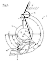
- Fig. 1 shows a schematic representation of a Schwenkaktor device 1 according to the invention in the installed position in a cylinder head 3.
- the Schwenkaktor device 1 consists essentially of a pivot motor 4 with a stator, not shown, and a rotor, not shown.
- the rotor is fixedly connected to a shaft 5 with a common axis of rotation 5a.
- the shaft 5 has radially at its periphery an actuating element 6 with a first control track 7, a half cam on.
- the first control path 7 is divided into three individual regions, a first zero-stroke region 7a, a first stroke region 7b and a full-stroke region 7c.
- a second actuating element 8 with a second control path 9 adjoins the first zero-stroke region 7a in the opposite direction of rotation.
- the second control track 9 is likewise subdivided into three areas, a second zero stroke area 9a, a second stroke area 9b and a partial lift area 9c.
- the second stroke region 9b is in turn divided into an acceleration stroke region 9b ', which adjoins the second zero stroke region 9a, followed by a delay stroke region 9b "The first zero stroke region 7a and the second zero stroke region 9a adjacent thereto have the same constant radius" R1 ".
- the distance between the first control track 7 in the first stroke region 7b increases in accordance with a cam contour via a rotation angle in the direction of the full stroke region 7c
- the full stroke region 7c following the first stroke region 7b in turn has a constant radius "R2" Radius difference between R2 and R1 corresponds to a height "h 1 ", corresponding to a maximum gas exchange valve lift
- the second stroke region 9b adjoining the second zero stroke region 9a also has a cam contour, that is, the distance of the control path 9 from the rotation axis 5a increases in the lifting area 9b via a twist angle in the direction Operahu b range 9c.
- the acceleration stroke region 9b ' has a degressive, the delay stroke region 9b "a progressive radius increase.
- the acceleration stroke range 9b compensates for the kinematics torque of the spring element only to a small extent and thus imposes spring-induced acceleration on the system
- the kinematic moment of the spring element 12 is overcompensated in the deceleration stroke range 9b "and thus the system is impressed with spring-induced deceleration over this stroke range 9b 'and the delay stroke 9b "can occupy different angular sections of the control track 9 depending on the internal combustion engine or omitted entirely in favor of a normal cam contour.
- the power transmission element 10 is based, on the one hand, on a clearance compensation element 14, a hydraulic valve clearance compensation element, which is arranged stationarily in the cylinder head 3 and, on the other hand, on a valve stem end of a gas exchange valve 2 which is held in the closed position by a valve spring 11.
- the swivel motor 4 pivots at high requested load or speed in the direction of the full-stroke range 7c and at a lower requested load or speed in the direction of the partial lift ranges 9c.
- the gas exchange valve 2 is opened in accordance with the control tracks 7 and 9, respectively.
- the pivoting movement of the swivel motor 4 is assisted during opening by the spring element 12 and the energy stored in the spring element 12 is delivered to the valve spring 11 during the opening process.
- the valve spring 11 is the stored energy in her largely to the spring element 12 from.
- Subsequent partial lifting area 9c is a torque-neutral cam area in which electroless holding of gas exchange valve 2 in the open position, at maximum partial lift, especially at low engine speeds and high loads, is made possible.
- the height h 2 of the Operahub Schemees 9c is designed according to internal combustion engine-dependent parameters.
- the acceleration stroke region 9b 'of the second actuating element 8 can be made smaller in magnitude than the region of the deceleration stroke region 9b.
- the load control of the internal combustion engine is simpler and allows more fuel-efficient operating points in the lower load range.
- Another advantage of the Schwenkaktor device 1 according to the invention is the lower power consumption at low speeds at small valve strokes against full valve lifts to mention. Due to the small air gap with a small valve lift of the inlet valve, it is possible to achieve supersonic inlet flow rates which improve the mixture preparation and thus reduce the emissions of the internal combustion engine. A further improvement results from opening the intake valve twice, a first time to draw in the combustion air and a second time to swirl the combustion air with fuel. This leads to a significantly improved mixing of air and fuel and thus to a more uniform combustion.
- the opening speed of the valve movement can be reduced if desired, and thus reduces the Vorlassauspat in the exhaust system become.
- the acoustic excitation of the exhaust system can be reduced and the overall noise level of the internal combustion engine can also be reduced.
Landscapes
- Engineering & Computer Science (AREA)
- Mechanical Engineering (AREA)
- General Engineering & Computer Science (AREA)
- Valve Device For Special Equipments (AREA)
Abstract
Description
- Die Erfindung betrifft eine Schwenkaktor-Vorrichtung zur Hubsteuerung eines Gaswechselventils in einem Zylinderkopf einer Brennkraftmaschine gemäß der Merkmale im Oberbegriff des Patentanspruchs 1.
- Sie geht von der US 5,873,335 aus. In dieser ist eine Schwenkaktor-Vorrichtung zur Hubsteuerung eines Gaswechselventils in einem Zylinderkopf einer Brennkraftmaschine, bestehend aus einem Schwenkmotor mit einer Welle, an die ein Betätigungselement mit einer Steuerbahn angeordnet ist, beschrieben. Das Betätigungselement dient zum Öffnen eines Gaswechselventils, wobei an das erste Betätigungselement ein zweites Betätigungselement mit einer zweiten Steuerbahn angeordnet ist.
- Nachteilig bei der beschriebenen Schwenkaktor-Vorrichtung ist es, dass das Gaswechselventil trotz der o. g. Ausgestaltung, nur mit einem Ventilhubverlauf betätigbar ist.
- Aufgabe der vorliegenden Erfindung ist es, eine gattungsgemäße Schwenkaktor-Vorrichtung dahingehend weiter auszubilden, dass für das Gaswechselventil unterschiedliche Ventilhubverläufe möglich sind.
- Diese Aufgabe wird durch die Merkmale im kennzeichnenden Teil des Patentanspruchs 1 gelöst.
- Die Erfindung erweitert die bestehende Schwenkaktor-Vorrichtung durch ein zweites Betätigungselement in gegenläufiger Drehrichtung mit einem geringeren Hub gegenüber der Hauptnocke. Dieses zweite Betätigungselement öffnet das Ventil nicht komplett und wird nur für kleine Hübe im Bereich niedriger Motordrehzahlen verwendet. Bei niedrigen Drehzahlen der Brennkraftmaschine wird die Schwenkaktor-Vorrichtung derart bestromt, dass die Welle nur in Richtung des zweiten Betätigungselementes schwenkt, während bei hohen Drehzahlen ausschließlich in Richtung des ersten Betätigungselementes geschwenkt wird. Durch den geringen Hub verbraucht die Schwenkaktor-Vorrichtung bei niedrigen Drehzahlen in vorteilhafter Weise weniger Strom.
- Durch die Ausgestaltung gemäß Patentanspruch 2 bilden die zwei Betätigungselemente einen Doppelnocken, der stoßfrei in zwei Richtungen betätigbar ist. Darüber hinaus ist die Fertigung einer derart gestalteten doppelten Steuerbahn, deren Nullhubbereiche aneinandergeordnet sind, einfach und kostengünstig.
- Mit einer Ausgestaltung gemäß der Patentansprüche 3 bis 6 ist die Stromaufnahme bei niedrigen Drehzahlen gering. Ferner werden durch Aufschlagen des Gaswechselventils auf dem Ventilsitz generierte Ventilgeräusche durch die erfindungsgemäße Ausgestaltung reduziert. Das zweite Betätigungselement gleicht die Momente des Federelementes, einer Aktorfeder, gegen die Momente der Ventilfeder aus. Damit ist das resultierende Moment an der Nockenwelle nahezu Null, abhängig von Toleranzen, und somit kann die Nockenwelle in jeder Winkelstellung des zweiten Betätigungselementes nahezu stromlos gehalten werden. Ein derartiges System hat eine geringe Dynamik, da diese allein von dem Momentaufbau des Schwenkmotors (durch Bestromung) aufgebaut wird. Als weiterer Vorteil ist die Verbesserung der Gasdynamik beim Ladungswechsel zu nennen, da aufgrund des kleinen Ventilhubs Überschallgeschwindigkeiten im Ventilspalt erzeugbar sind, die wesentlich zu einer guten Gemischaufbereitung positiv beitragen. Insbesondere bei einer Ausgestaltung gemäß Patentanspruch 5 wirken sich Systemüberschwinger nicht aus, da der Ventilhub in diesen Bereichen nicht verändert wird.
- Um die geringe Dynamik des zweiten Betätigungselementes zu verbessern, ist die zweite Steuerbahn gemäß der Patentansprüche 7 bis 9 ausgestaltet. Hierzu ist die Steuerbahn in zwei Bereiche aufgeteilt. Im ersten Hubbereich, ab Nullhub oder einem definierten Wert (z. B. ab 0,6 mm bis 1,5 mm Hubhöhe), wird das Kinematikmoment des Federelementes nur zu einem geringen Teil kompensiert, damit der Schwenkaktor-Vorrichtung eine federbedingte Beschleunigung aufgeprägt wird. Im zweiten Hubbereich (z. B. ab 1,5 mm bis ca. 3,5 mm) wird das Kinematikmoment des Federelementes überkompensiert, damit der Schwenkaktor-Vorrichtung eine federbedingte Abbremsung über diesen Hubbereich aufgeprägt wird. Durch diese Ausgestaltung ist es in einfacher Weise möglich, die Dynamik der Schwenkaktor-Vorrichtung, insbesondere für kleine Ventilhübe positiv zu beeinflussen.
- Gemäß Patentanspruch 10 ist es möglich, die zwei Betätigungselemente entweder radial am Außenumfang der Welle anzuordnen, wodurch von einer Schwenkaktor-Vorrichtung mehrere Gaswechselventile betrieben werden können bzw. an der stirnseitigen Fläche der Welle eine Kulissenbahn anzubringen, mit der ein einzelnes Gaswechselventil steuerbar ist.
- Bei Anordnung eines Kraftübertragungselementes zwischen Betätigungselement und Gaswechselventil gemäß Patentanspruch 11 und 12 wird die innere Reibung des Systems verringert.
- In vorteilhafter Weise kann die erfindungsgemäße Schwenkaktor-Vorrichtung gemäß Patentanspruch 13 sowohl einlassseitig als auch auslassseitig im Zylinderkopf der Brennkraftmaschine angeordnet werden. Dieses Gleichteileprinzip ermöglicht eine kostengünstige Fertigung.
- Im Folgenden ist ein bevorzugtes Ausführungsbeispiel anhand einer einzigen Figur näher erläutert.
- Fig. 1 zeigt eine schematische Darstellung einer erfindungsgemäßen Schwenkaktor-Vorrichtung 1 in Einbaulage in einem Zylinderkopf 3. Die Schwenkaktor-Vorrichtung 1 besteht im Wesentlichen aus einem Schwenkmotor 4 mit einem nicht dargestellten Stator und einem nicht dargestellten Rotor. Der Rotor ist mit einer Welle 5 mit einer gemeinsamen Drehachse 5a ortsfest verbunden. Die Welle 5 weist radial an ihrem Umfang ein Betätigungselement 6 mit einer ersten Steuerbahn 7, eine halbe Nocke, auf. Die erste Steuerbahn 7 teilt sich in drei Einzelbereiche, einen ersten Nullhubbereich 7a, einen ersten Hubbereich 7b und einen Vollhubbereich 7c auf. An den ersten Nullhubbereich 7a schließt sich in entgegengesetzter Drehrichtung ein zweites Betätigungselement 8 mit einer zweiten Steuerbahn 9 an. Die zweite Steuerbahn 9 ist ebenfalls in drei Bereiche, einen zweiten Nullhubbereich 9a, einen zweiten Hubbereich 9b und einen Teilhubbereich 9c unterteilt. Der zweite Hubbereich 9b ist wiederum unterteilt in einen Beschleunigungshubbereich 9b', der sich an den zweiten Nullhubbereich 9a anschließt, daran schließt sich ein Verzögerungshubbereich 9b" an. Der erste Nullhubereich 7a und der daran angrenzende zweite Nullhubbereich 9a weisen den selben konstanten Radius "R1" bezogen auf die Drehachse 5a auf. Der Abstand der ersten Steuerbahn 7 im ersten Hubbereich 7b nimmt entsprechend einer Nockenkontur über einen Verdrehwinkel in Richtung Vollhubbereich 7c zu. Der an den ersten Hubbereich 7b anschließende Vollhubbereich 7c weist wiederum einen konstanten Radius "R2" auf. Die Radiusdifferenz zwischen R2 und R1 entspricht einer Höhe "h1", entsprechend einem maximalen Gaswechsel-Ventilhub. Der an den zweiten Nullhubbereich 9a anschließende zweite Hubbereich 9b weist ebenfalls eine Nockenkontur auf, das heißt, der Abstand der Steuerbahn 9 von der Drehachse 5a vergrößert sich im Hubbereich 9b über einen Verdrehwinkel in Richtung Teilhubbereich 9c. Der Beschleunigungshubbereich 9b' weist eine degressive, der Verzögerungshubbereich 9b" eine progressive Radiuszunahme auf. Der an den Verzögerungshubbereich 9b" anschließende Teilhubbereich 9c weist einen konstanten Radius "R3" in Bezug auf die Drehachse 5a auf. Die Radiusdifferenz zwischen R3 und R1 entspricht einer Höhe "h2", einem mittleren Gaswechsel-Ventilhub. Der Beschleunigungshubbereich 9b' beginnt im vorliegenden Beispiel ab einem Hub von 0,6 mm und erstreckt sich bis zu einer Hubhöhe von 1,5 mm. Der Verzögerungshubbereich 9b" beginnt ab einer Hubhöhe von 1,5 mm und reicht bis zu einer Hubhöhe von 3,5 mm. Während der Beschleunigungshubbereich 9b' das Kinematikmoment des Federelementes nur zu einem geringen Teil kompensiert, und somit dem System eine federbedingte Beschleunigung aufprägt, wird im Verzögerungshubbereich 9b" das Kinematikmoment des Federelementes 12 überkompensiert und damit dem System eine federbedingte Abbremsung über diesen Hubbereich aufgeprägt. Der Beschleunigungshubbereich 9b' und der Verzögerungshubbereich 9b" können abhängig von der Brennkraftmaschine unterschiedliche Winkelabschnitte der Steuerbahn 9 einnehmen oder ganz entfallen zugunsten einer normalen Nockenkontur.
- In der Darstellung ist der zweite Nullhubbereich 9a mit einem Rollenelement 10a eines Kraftübertragungselementes 10, einem Rollenschlepphebel, in Wirkverbindung. Das Kraftübertragungselement 10 stützt sich einerseits auf einem Spielausgleichselement 14, einem hydraulischem Ventilspielausgleichselement, ab, das ortsfest im Zylinderkopf 3 angeordnet ist und andererseits an einem Ventilschaftende eines Gaswechselventils 2, das von einer Ventilfeder 11 in Schließstellung gehalten wird. Weiter ist an der Welle 5 ein ortsfestes Abstützelement 13, an dem ein Federelement 12, eine Schenkelfeder, einerseits abgestützt ist, während es andererseits am Zylinderkopf 3 lagefixiert ist.
- Beim Betrieb der Brennkraftmaschine schwenkt der Schwenkmotor 4 bei hoher angeforderter Last, bzw. Drehzahl in Richtung Vollhubbereich 7c und bei niedriger angeforderter Last, bzw. Drehzahl in Richtung Teilhubbereiche 9c. Bei der periodischen Schwenkbewegung in die eine oder andere Richtung wird entsprechend der Steuerbahnen 7 bzw. 9 das Gaswechselventil 2 geöffnet. Die Schwenkbewegung des Schwenkmotors 4 wird hierbei beim Öffnen vom Federelement 12 unterstützt und die im Federelement 12 gespeicherte Energie wird bei dem Öffnungsvorgang an die Ventilfeder 11 abgegeben. Beim Schließvorgang, beim Schwenken in Richtung ersten und zweiten Nullhubbereich 7a, 9a, gibt die Ventilfeder 11 die in ihr gespeicherte Energie weitestgehend an das Federelement 12 ab. Durch dieses Feder-Masse-Feder-Schwingsystem ist der Energiebedarf des Schwenkmotors 4, insbesondere bei kleinem Ventilhub, sehr gering.
- Der im Anschluss angeordnete Teilhubbereich 9c ist ein momentneutraler Nockenbereich, in dem ein stromloses Halten des Gaswechselventils 2 in der Offenstellung, bei maximalem Teilhub, besonders bei niedrigen Motordrehzahlen und hohen Lasten ermöglicht wird. Die Höhe h2 des Teilhubbereiches 9c wird entsprechend brennkraftmaschinenabhängiger Parameter ausgelegt. Für die Einlassseite einer Brennkraftmaschine kann der Beschleunigungshubbereich 9b' des zweiten Betätigungselementes 8 vom Betrag her kleiner ausgeführt werden, als der Bereich des Verzögerungshubbereiches 9b". Auf diese Weise kann eine Variabilität der zweiten Steuerbahn 9 und damit eine bessere Gemischsteuerung der Brennkraftmaschine erreicht werden. Für die Auslassseite einer Brennkraftmaschine können der Beschleunigungshubbereich 9b' und der Verzögerungshubbereich 9b" den gleichen Arbeitsbetrag haben, um eine möglichst hohe Dynamik der Teilhubbewegung zu erreichen, und damit den Betriebsbereich des Teilhubbetriebes vom Leerlauf bis zu möglichst hohen Drehzahlen zu erweitern.
- Durch die kleinen, variablen Hübe ist die Laststeuerung der Brennkraftmaschine einfacher und ermöglicht verbrauchsgünstigere Betriebspunkte im unteren Lastbereich. Als weiterer Vorteil der erfindungsgemäßen Schwenkaktor-Vorrichtung 1 ist der geringere Strombedarf bei niedrigen Drehzahlen bei kleinen Ventilhüben gegenüber vollen Ventilhüben zu erwähnen. Durch den kleinen Luftspalt bei geringem Ventilhub des Einlassventils lassen sich Überschalleinlassströmungsgeschwindigkeiten erreichen, welche die Gemischaufbereitung verbessern und somit die Emissionen der Brennkraftmaschine reduzieren. Eine weitere Verbesserung ergibt sich beim zweimaligen Öffnen des Einlassventils, ein erstes Mal zum Ansaugen der Verbrennungsluft und ein zweites Mal zum Verwirbeln der Verbrennungsluft mit Kraftstoff. Dies führt zu einer wesentlich verbesserten Vermischung von Luft und Treibstoff und somit zu einer gleichmäßigeren Verbrennung. Auf der Auslassseite der Brennkraftmaschine kann die Öffnungsgeschwindigkeit der Ventilbewegung auf Wunsch reduziert werden und damit der Vorlassausstoß in der Abgasanlage vermindert werden. Somit kann die akustische Anregung der Abgasanlage reduziert und der Gesamtgeräuschpegel der Brennkraftmaschine ebenfalls reduziert werden.
-
- 1
- Schwenkaktor-Vorrichtung
- 2
- Gaswechselventil
- 3
- Zylinderkopf
- 4
- Schwenkmotor
- 5
- Welle
- 5a
- Drehachse
- 6
- Betätigungselement
- 7
- erste Steuerbahn
- 7a
- erster Nullhubbereich
- 7b
- erster Hubbereich
- 7c
- Vollhubbereich
- 8
- Zweites Betätigungselement
- 9a
- Zweiter Nullhubbereich
- 9b
- Zweiter Hubbereich
- 9b'
- Beschleunigungshubbereich
- 9b"
- Verzögerungshubbereich
- 9c
- Teilhubbereich
- 10
- Kraftübertragungselement
- 10a
- Rollenelement
- 11
- Ventilfeder
- 12
- Federelement
- 13
- Abstützelement
- 14
- Spielausgleichselement
Claims (13)
- Schwenkaktor-Vorrichtung (1) zur Hubsteuerung eines Gaswechselventils (2) in einem Zylinderkopf (3) einer Brennkraftmaschine, bestehend aus einem Schwenkmotor (4) mit einer Welle (5), an die ein Betätigungselement (6) mit einer ersten Steuerbahn (7) zum Öffnen des Gaswechselventils (2) angeordnet ist, wobei die erste Steuerbahn (7) in einen ersten Nullhubbereich (7a) und einen ersten Hubbereich (7b) unterteilt ist,
dadurch gekennzeichnet, dass an das erste Betätigungselement (6) ein zweites Betätigungselement (8) mit einer zweiten Steuerbahn (9) zum Öffnen des Gaswechselventils (2) angeordnet ist und die zweite Steuerbahn (9) in zumindest einen zweiten Nullhubbereich (9a) und einen zweiten Hubbereich (9b) unterteilt ist. - Vorrichtung nach Patentanspruch 1,
dadurch gekennzeichnet, dass der zweite Nullhubbereich (9a) an den ersten Nullhubbereich (7a) der ersten Steuerbahn (7) angeordnet ist. - Vorrichtung nach Patentanspruch 1 oder 2,
dadurch gekennzeichnet, dass die erste Steuerbahn (7) einen Vollhubbereich (7c) und/oder die zweite Steuerbahn (9) einen Teilhubbereich (9c) aufweist. - Vorrichtung nach Patentanspruch 3,
dadurch gekennzeichnet, dass der Vollhubbereich (7c) an den ersten Hubbereich (7b) und der Teilhubbereich (9c) an den zweiten Hubbereich (9b) angeordnet ist. - Vorrichtung nach einem der zuvor genannten Patentansprüche,
dadurch gekennzeichnet, dass eine Hubhöhe (h2) des Teilhubbereichs (9c) kleiner als eine Hubhöhe (h1) des Vollhubbereichs (7c) ist. - Vorrichtung nach einem der zuvor genannten Patentansprüche,
dadurch gekennzeichnet, dass die Hubhöhe (h1) des Vollhubbereichs (7c) die maximale Hubhöhe des Gaswechselventils (2) ist. - Vorrichtung nach einem der zuvor genannten Patentansprüche,
dadurch gekennzeichnet, dass der zweite Hubbereich (9b) ausgehend von dem zweiten Nullhubbereich (9a) in einen Beschleunigungshubbereich (9b') und daran anschließend in einen Verzögerungshubbereich (9b") unterteilt ist. - Vorrichtung nach Patentanspruch 7, wobei die Welle (5) um eine Drehachse (5a) schwenkt,
dadurch gekennzeichnet, dass ein Abstand der Steuerbahn (9) im Beschleunigungshubbereich (9b') zur Drehachse (5a) über einen Verdrehwinkel in Richtung Teilhubbereich (9c) degressiv zunimmt. - Vorrichtung nach Patentanspruch 7,
dadurch gekennzeichnet, dass ein Abstand der Steuerbahn (9) im Verzögerungshubbereich (9b") zur Drehachse (5a) über einen Verdrehwinkel in Richtung Teilhubbereich (9c) progressiv zunimmt. - Vorrichtung nach Patentanspruch 5,
dadurch gekennzeichnet, dass das Betätigungselement (6) und das zweite Betätigungselement (8) radial oder axial an der Welle (5) angeordnet sind. - Vorrichtung nach einem der zuvor genannten Patentansprüche,
dadurch gekennzeichnet, dass zwischen dem Betätigungselement (6, 8) und dem Gaswechselventil (2) ein Kraftübertragungselement (10) angeordnet ist. - Vorrichtung nach Patentanspruch 11,
dadurch gekennzeichnet, dass das Kraftübertragungselement (10) ein Schlepphebel oder ein Rollenschtepphebel oder ein Kipphebel ist. - Vorrichtung nach einem der zuvor genannten Patentansprüche, wobei die Brennkraftmaschine Einlass-Gaswechselventile und Auslass-Gaswechselventile aufweist,
dadurch gekennzeichnet, dass die Schwenkaktor-Vorrichtung (1) an Einlass-Gaswechselventilen und/oder Auslass-Gaswechselventilen anordenbar ist.
Applications Claiming Priority (3)
| Application Number | Priority Date | Filing Date | Title |
|---|---|---|---|
| DE10252991A DE10252991A1 (de) | 2002-11-14 | 2002-11-14 | Schwenkaktor-Vorrichtung zur Hubsteuerung eines Gaswechselventils im Zylinderkopf einer Brennkraftmaschine |
| DE10252991 | 2002-11-14 | ||
| PCT/EP2003/011409 WO2004044392A1 (de) | 2002-11-14 | 2003-10-15 | Schwenkaktor-vorrichtung zur hubsteuerung eines gaswechselventils im zylinderkopf einer brennkraftmaschine |
Publications (2)
| Publication Number | Publication Date |
|---|---|
| EP1561011A1 EP1561011A1 (de) | 2005-08-10 |
| EP1561011B1 true EP1561011B1 (de) | 2006-12-13 |
Family
ID=32185627
Family Applications (1)
| Application Number | Title | Priority Date | Filing Date |
|---|---|---|---|
| EP03750715A Expired - Lifetime EP1561011B1 (de) | 2002-11-14 | 2003-10-15 | Schwenkaktor-vorrichtung zur hubsteuerung eines gaswechselventils im zylinderkopf einer brennkraftmaschine |
Country Status (4)
| Country | Link |
|---|---|
| US (1) | US7111598B2 (de) |
| EP (1) | EP1561011B1 (de) |
| DE (2) | DE10252991A1 (de) |
| WO (1) | WO2004044392A1 (de) |
Families Citing this family (19)
| Publication number | Priority date | Publication date | Assignee | Title |
|---|---|---|---|---|
| DE10311275A1 (de) * | 2003-03-14 | 2004-09-30 | Bayerische Motoren Werke Ag | Ventiltrieb für einen Verbrennungsmotor |
| JP4049092B2 (ja) * | 2003-12-12 | 2008-02-20 | トヨタ自動車株式会社 | 動弁装置 |
| DE102004054775B4 (de) * | 2004-11-12 | 2006-09-21 | Bayerische Motoren Werke Ag | Vorrichtung und Verfahren zur Regelung des Hubverlaufes eines Auslass-Gaswechselventils einer Brennkraftmaschine |
| DE102004054773B4 (de) * | 2004-11-12 | 2006-12-28 | Bayerische Motoren Werke Ag | Vorrichtung zur Regelung des Hubverlaufes eines Gaswechselventils einer Brennkraftmaschine |
| DE102004054759B4 (de) * | 2004-11-12 | 2006-08-10 | Bayerische Motoren Werke Ag | Verfahren zur Kalibrierung eines Wegsensors einer Drehaktuatorvorrichtung zur Ansteuerung eines Gaswechselventils einer Brennkraftmaschine |
| DE102004054776B3 (de) | 2004-11-12 | 2006-03-16 | Bayerische Motoren Werke Ag | Verfahren zur Kalibrierung eines Wegsensors einer Drehaktuatorvorrichtung zur Ansteuerung eines Gaswechselventils einer Brennkraftmaschine |
| DE102004054740B4 (de) * | 2004-11-12 | 2007-10-25 | Bayerische Motoren Werke Ag | Verfahren zur Erkennung eines Fehlers in einem Wegsignal eines Wegsensors einer Drehaktuatorvorrichtung |
| DE102006005944A1 (de) * | 2006-02-09 | 2007-08-23 | Bayerische Motoren Werke Ag | Verbrennungsmotor mit einem elektrischen Ventiltrieb |
| JP4412318B2 (ja) | 2006-03-20 | 2010-02-10 | トヨタ自動車株式会社 | 弁駆動装置 |
| US7708254B2 (en) | 2007-08-07 | 2010-05-04 | Warren Controls, Inc. | Actuator apparatus for operating and locking a control valve and a method for its use |
| GB0920152D0 (en) * | 2009-11-18 | 2009-12-30 | Camcon Ltd | Rotary electromagnetic actuator |
| ES2390400T3 (es) | 2009-12-16 | 2012-11-12 | Iveco Motorenforschung Ag | Sistema de accionamiento de válvula variable mecánico para funcionamientos de motor de 2 tiempos y de 4 tiempos |
| US8360387B2 (en) * | 2010-03-26 | 2013-01-29 | Bose Corporation | Actuator including mechanism for converting rotary motion to linear motion |
| KR101209736B1 (ko) * | 2010-09-30 | 2012-12-07 | 기아자동차주식회사 | 가변 밸브 리프트 장치 |
| US11353084B2 (en) | 2013-03-15 | 2022-06-07 | Clearmotion Acquisition I Llc | Rotary actuator driven vibration isolation |
| US9291300B2 (en) | 2013-03-15 | 2016-03-22 | Bose Corporation | Rotary actuator driven vibration isolation |
| GB201616956D0 (en) * | 2016-10-06 | 2016-11-23 | Jaguar Land Rover Limited | Method of controlling a valve train |
| GB2563064B (en) * | 2017-06-02 | 2022-05-18 | Camcon Auto Ltd | Valve actuators |
| US11401838B2 (en) | 2020-12-03 | 2022-08-02 | Jacobs Vehicle Systems, Inc. | Rotating actuator system for controlling valve actuation in an internal combustion engine |
Family Cites Families (8)
| Publication number | Priority date | Publication date | Assignee | Title |
|---|---|---|---|---|
| US3261338A (en) * | 1964-07-13 | 1966-07-19 | Automobile Racing Club Of Okla | Valve timing mechanism |
| US4723516A (en) * | 1985-11-25 | 1988-02-09 | Slagley Michael W | Valve open duration and timing controller |
| US4864984A (en) * | 1986-09-02 | 1989-09-12 | Blish Nelson A | Rotary valve internal combustion engine |
| US5253546A (en) * | 1990-05-29 | 1993-10-19 | Clemson University | Variable valve actuating apparatus |
| US5873335A (en) * | 1998-01-09 | 1999-02-23 | Siemens Automotive Corporation | Engine valve actuation control system |
| DE19913742A1 (de) * | 1999-03-26 | 2000-09-28 | Bayerische Motoren Werke Ag | Vorrichtung zur Hubverstellung eines Gaswechselventils im Zylinderkopf einer Brennkraftmaschine |
| DE10120449A1 (de) * | 2001-04-26 | 2002-10-31 | Ina Schaeffler Kg | Elektromotorisch verdrehbare Welle |
| DE10140461A1 (de) * | 2001-08-17 | 2003-02-27 | Bayerische Motoren Werke Ag | Drehaktor-Vorrichtung zur Hubsteuerung eines Gaswechselventils im Zylinderkopf einer Brennkraftmaschine |
-
2002
- 2002-11-14 DE DE10252991A patent/DE10252991A1/de not_active Withdrawn
-
2003
- 2003-10-15 EP EP03750715A patent/EP1561011B1/de not_active Expired - Lifetime
- 2003-10-15 DE DE50305989T patent/DE50305989D1/de not_active Expired - Lifetime
- 2003-10-15 WO PCT/EP2003/011409 patent/WO2004044392A1/de not_active Ceased
-
2005
- 2005-05-13 US US11/128,185 patent/US7111598B2/en not_active Expired - Fee Related
Also Published As
| Publication number | Publication date |
|---|---|
| DE50305989D1 (de) | 2007-01-25 |
| EP1561011A1 (de) | 2005-08-10 |
| US7111598B2 (en) | 2006-09-26 |
| US20060016408A1 (en) | 2006-01-26 |
| WO2004044392A1 (de) | 2004-05-27 |
| DE10252991A1 (de) | 2004-05-27 |
Similar Documents
| Publication | Publication Date | Title |
|---|---|---|
| EP1561011B1 (de) | Schwenkaktor-vorrichtung zur hubsteuerung eines gaswechselventils im zylinderkopf einer brennkraftmaschine | |
| DE10063997C2 (de) | Variable Ventilbetätigungsvorrichtung für Motoren mit innerer Verbrennung | |
| DE10140635B4 (de) | Vorrichtung zur variablen Ventilhubverstellung von Gaswechselventilen einer Verbrennungskraftmaschine | |
| DE19815112B4 (de) | Anordnung zur variablen Ventilzeitsteuerung und Ventilbetätigung | |
| DE19548389A1 (de) | Verstellvorrichtung für den Hubverlauf eines Gaswechselventils einer Brennkraftmaschine | |
| EP2118454B1 (de) | Ventiltrieb eines hubkolben-verbrennungsmotors | |
| DE102004008350A1 (de) | Motorventilbetätigungssystem | |
| DE10228022A1 (de) | Ventilhubvorrichtung zur Hubverstellung der Gaswechselventile einer Verbrennungskraftmaschine | |
| EP1853797B1 (de) | Variable mechanische ventilsteuerung einer brennkraftmaschine | |
| DE69303740T2 (de) | Ventilantrieb für eine Brennkraftmaschine | |
| EP0244878B1 (de) | Elektromagnetisch-hydraulischer Ventiltrieb für Verbrennungskraftmaschinen | |
| EP1760278A2 (de) | Hubvariabler Ventiltrieb für eine Brennkraftmaschine | |
| DE4410034B4 (de) | Ventilsteuersystem eines Motors | |
| EP1375843B1 (de) | Brennkraftmaschine mit innerer Verbrennung | |
| DE102007020129A1 (de) | Raumnockenventiltrieb mit modifizierter Raumnockengeometrie | |
| EP1608852B1 (de) | Vorrichtung zur variablen bet tigung der gaswechselventile v on verbrennungsmotoren und verfahren zum betreiben einer derartigen vorrichtung | |
| DE102018130428A1 (de) | Hubvariabler Ventiltrieb mit wenigstens zwei Arbeitslagen | |
| DE102020109260A1 (de) | Ventilsteuerung für eine Ventilabschaltung und Ventilhubumschaltung | |
| DE10251007B4 (de) | Mit fremdzündbaren Kraftstoff betriebene Brennkraftmaschine | |
| EP2716882B1 (de) | Mechanisch steuerbarer Ventiltrieb für eine Hubkolbenmaschine | |
| WO2021115711A1 (de) | Hubsteller für einen hubvariablen ventiltrieb mit zwei arbeitslagen | |
| DE102006002133B4 (de) | Ventiltrieb zur hubvariablen Betätigung eines Gaswechselventils einer Brennkraftmaschine | |
| WO2017174353A1 (de) | Ventiltrieb sowie motorbaugruppe | |
| DE10323665A1 (de) | Variable Ventilhubvorrichtung zur Hubverstellung der Gaswechselventile einer Verbrennungskraftmaschine | |
| DE102011116439A1 (de) | Ventiltriebvorrichtung mit vollvariabler Ventilhubumstellung für eine Brennkraftmaschine |
Legal Events
| Date | Code | Title | Description |
|---|---|---|---|
| PUAI | Public reference made under article 153(3) epc to a published international application that has entered the european phase |
Free format text: ORIGINAL CODE: 0009012 |
|
| 17P | Request for examination filed |
Effective date: 20050126 |
|
| AK | Designated contracting states |
Kind code of ref document: A1 Designated state(s): AT BE BG CH CY CZ DE DK EE ES FI FR GB GR HU IE IT LI LU MC NL PT RO SE SI SK TR |
|
| RBV | Designated contracting states (corrected) |
Designated state(s): DE FR GB IT |
|
| GRAP | Despatch of communication of intention to grant a patent |
Free format text: ORIGINAL CODE: EPIDOSNIGR1 |
|
| GRAS | Grant fee paid |
Free format text: ORIGINAL CODE: EPIDOSNIGR3 |
|
| GRAA | (expected) grant |
Free format text: ORIGINAL CODE: 0009210 |
|
| AK | Designated contracting states |
Kind code of ref document: B1 Designated state(s): DE FR GB IT |
|
| REG | Reference to a national code |
Ref country code: GB Ref legal event code: FG4D Free format text: NOT ENGLISH |
|
| REF | Corresponds to: |
Ref document number: 50305989 Country of ref document: DE Date of ref document: 20070125 Kind code of ref document: P |
|
| GBT | Gb: translation of ep patent filed (gb section 77(6)(a)/1977) |
Effective date: 20070123 |
|
| ET | Fr: translation filed | ||
| PLBE | No opposition filed within time limit |
Free format text: ORIGINAL CODE: 0009261 |
|
| STAA | Information on the status of an ep patent application or granted ep patent |
Free format text: STATUS: NO OPPOSITION FILED WITHIN TIME LIMIT |
|
| 26N | No opposition filed |
Effective date: 20070914 |
|
| PGFP | Annual fee paid to national office [announced via postgrant information from national office to epo] |
Ref country code: IT Payment date: 20081029 Year of fee payment: 6 |
|
| PGFP | Annual fee paid to national office [announced via postgrant information from national office to epo] |
Ref country code: GB Payment date: 20081029 Year of fee payment: 6 |
|
| PG25 | Lapsed in a contracting state [announced via postgrant information from national office to epo] |
Ref country code: GB Free format text: LAPSE BECAUSE OF NON-PAYMENT OF DUE FEES Effective date: 20091015 |
|
| PG25 | Lapsed in a contracting state [announced via postgrant information from national office to epo] |
Ref country code: IT Free format text: LAPSE BECAUSE OF NON-PAYMENT OF DUE FEES Effective date: 20091015 |
|
| REG | Reference to a national code |
Ref country code: FR Ref legal event code: PLFP Year of fee payment: 13 |
|
| PGFP | Annual fee paid to national office [announced via postgrant information from national office to epo] |
Ref country code: DE Payment date: 20151031 Year of fee payment: 13 |
|
| PGFP | Annual fee paid to national office [announced via postgrant information from national office to epo] |
Ref country code: FR Payment date: 20151029 Year of fee payment: 13 |
|
| REG | Reference to a national code |
Ref country code: DE Ref legal event code: R119 Ref document number: 50305989 Country of ref document: DE |
|
| REG | Reference to a national code |
Ref country code: FR Ref legal event code: ST Effective date: 20170630 |
|
| PG25 | Lapsed in a contracting state [announced via postgrant information from national office to epo] |
Ref country code: DE Free format text: LAPSE BECAUSE OF NON-PAYMENT OF DUE FEES Effective date: 20170503 Ref country code: FR Free format text: LAPSE BECAUSE OF NON-PAYMENT OF DUE FEES Effective date: 20161102 |