EP1561010B1 - Centrale electrique a turbines a gaz et procede pour l'exploiter - Google Patents
Centrale electrique a turbines a gaz et procede pour l'exploiter Download PDFInfo
- Publication number
- EP1561010B1 EP1561010B1 EP03795991A EP03795991A EP1561010B1 EP 1561010 B1 EP1561010 B1 EP 1561010B1 EP 03795991 A EP03795991 A EP 03795991A EP 03795991 A EP03795991 A EP 03795991A EP 1561010 B1 EP1561010 B1 EP 1561010B1
- Authority
- EP
- European Patent Office
- Prior art keywords
- membrane
- gas turbine
- partial oxidation
- power plant
- oxidation reactor
- Prior art date
- Legal status (The legal status is an assumption and is not a legal conclusion. Google has not performed a legal analysis and makes no representation as to the accuracy of the status listed.)
- Expired - Lifetime
Links
Images

Classifications
-
- F—MECHANICAL ENGINEERING; LIGHTING; HEATING; WEAPONS; BLASTING
- F02—COMBUSTION ENGINES; HOT-GAS OR COMBUSTION-PRODUCT ENGINE PLANTS
- F02C—GAS-TURBINE PLANTS; AIR INTAKES FOR JET-PROPULSION PLANTS; CONTROLLING FUEL SUPPLY IN AIR-BREATHING JET-PROPULSION PLANTS
- F02C3/00—Gas-turbine plants characterised by the use of combustion products as the working fluid
- F02C3/20—Gas-turbine plants characterised by the use of combustion products as the working fluid using a special fuel, oxidant, or dilution fluid to generate the combustion products
- F02C3/30—Adding water, steam or other fluids for influencing combustion, e.g. to obtain cleaner exhaust gases
-
- C—CHEMISTRY; METALLURGY
- C01—INORGANIC CHEMISTRY
- C01B—NON-METALLIC ELEMENTS; COMPOUNDS THEREOF; METALLOIDS OR COMPOUNDS THEREOF NOT COVERED BY SUBCLASS C01C
- C01B13/00—Oxygen; Ozone; Oxides or hydroxides in general
- C01B13/02—Preparation of oxygen
- C01B13/0229—Purification or separation processes
- C01B13/0248—Physical processing only
- C01B13/0251—Physical processing only by making use of membranes
-
- C—CHEMISTRY; METALLURGY
- C01—INORGANIC CHEMISTRY
- C01B—NON-METALLIC ELEMENTS; COMPOUNDS THEREOF; METALLOIDS OR COMPOUNDS THEREOF NOT COVERED BY SUBCLASS C01C
- C01B3/00—Hydrogen; Gaseous mixtures containing hydrogen; Separation of hydrogen from mixtures containing it; Purification of hydrogen; Reversible storage of hydrogen
- C01B3/02—Production of hydrogen; Production of gaseous mixtures containing hydrogen
- C01B3/32—Production of hydrogen; Production of gaseous mixtures containing hydrogen by reaction of gaseous or liquid organic compounds with gasifying agents, e.g. water, carbon dioxide or air
- C01B3/34—Production of hydrogen; Production of gaseous mixtures containing hydrogen by reaction of gaseous or liquid organic compounds with gasifying agents, e.g. water, carbon dioxide or air by reaction of hydrocarbons with gasifying agents
- C01B3/38—Production of hydrogen; Production of gaseous mixtures containing hydrogen by reaction of gaseous or liquid organic compounds with gasifying agents, e.g. water, carbon dioxide or air by reaction of hydrocarbons with gasifying agents using catalysts
- C01B3/386—Catalytic partial combustion
-
- C—CHEMISTRY; METALLURGY
- C01—INORGANIC CHEMISTRY
- C01B—NON-METALLIC ELEMENTS; COMPOUNDS THEREOF; METALLOIDS OR COMPOUNDS THEREOF NOT COVERED BY SUBCLASS C01C
- C01B3/00—Hydrogen; Gaseous mixtures containing hydrogen; Separation of hydrogen from mixtures containing it; Purification of hydrogen; Reversible storage of hydrogen
- C01B3/02—Production of hydrogen; Production of gaseous mixtures containing hydrogen
- C01B3/32—Production of hydrogen; Production of gaseous mixtures containing hydrogen by reaction of gaseous or liquid organic compounds with gasifying agents, e.g. water, carbon dioxide or air
- C01B3/34—Production of hydrogen; Production of gaseous mixtures containing hydrogen by reaction of gaseous or liquid organic compounds with gasifying agents, e.g. water, carbon dioxide or air by reaction of hydrocarbons with gasifying agents
- C01B3/48—Production of hydrogen; Production of gaseous mixtures containing hydrogen by reaction of gaseous or liquid organic compounds with gasifying agents, e.g. water, carbon dioxide or air by reaction of hydrocarbons with gasifying agents followed by reaction of water vapour with carbon monoxide
-
- F—MECHANICAL ENGINEERING; LIGHTING; HEATING; WEAPONS; BLASTING
- F01—MACHINES OR ENGINES IN GENERAL; ENGINE PLANTS IN GENERAL; STEAM ENGINES
- F01K—STEAM ENGINE PLANTS; STEAM ACCUMULATORS; ENGINE PLANTS NOT OTHERWISE PROVIDED FOR; ENGINES USING SPECIAL WORKING FLUIDS OR CYCLES
- F01K23/00—Plants characterised by more than one engine delivering power external to the plant, the engines being driven by different fluids
- F01K23/02—Plants characterised by more than one engine delivering power external to the plant, the engines being driven by different fluids the engine cycles being thermally coupled
- F01K23/06—Plants characterised by more than one engine delivering power external to the plant, the engines being driven by different fluids the engine cycles being thermally coupled combustion heat from one cycle heating the fluid in another cycle
- F01K23/10—Plants characterised by more than one engine delivering power external to the plant, the engines being driven by different fluids the engine cycles being thermally coupled combustion heat from one cycle heating the fluid in another cycle with exhaust fluid of one cycle heating the fluid in another cycle
-
- F—MECHANICAL ENGINEERING; LIGHTING; HEATING; WEAPONS; BLASTING
- F02—COMBUSTION ENGINES; HOT-GAS OR COMBUSTION-PRODUCT ENGINE PLANTS
- F02C—GAS-TURBINE PLANTS; AIR INTAKES FOR JET-PROPULSION PLANTS; CONTROLLING FUEL SUPPLY IN AIR-BREATHING JET-PROPULSION PLANTS
- F02C3/00—Gas-turbine plants characterised by the use of combustion products as the working fluid
- F02C3/20—Gas-turbine plants characterised by the use of combustion products as the working fluid using a special fuel, oxidant, or dilution fluid to generate the combustion products
- F02C3/22—Gas-turbine plants characterised by the use of combustion products as the working fluid using a special fuel, oxidant, or dilution fluid to generate the combustion products the fuel or oxidant being gaseous at standard temperature and pressure
-
- F—MECHANICAL ENGINEERING; LIGHTING; HEATING; WEAPONS; BLASTING
- F02—COMBUSTION ENGINES; HOT-GAS OR COMBUSTION-PRODUCT ENGINE PLANTS
- F02C—GAS-TURBINE PLANTS; AIR INTAKES FOR JET-PROPULSION PLANTS; CONTROLLING FUEL SUPPLY IN AIR-BREATHING JET-PROPULSION PLANTS
- F02C6/00—Plural gas-turbine plants; Combinations of gas-turbine plants with other apparatus; Adaptations of gas-turbine plants for special use
- F02C6/18—Plural gas-turbine plants; Combinations of gas-turbine plants with other apparatus; Adaptations of gas-turbine plants for special use using the waste heat of gas-turbine plants outside the plants themselves, e.g. gas-turbine power heat plants
-
- C—CHEMISTRY; METALLURGY
- C01—INORGANIC CHEMISTRY
- C01B—NON-METALLIC ELEMENTS; COMPOUNDS THEREOF; METALLOIDS OR COMPOUNDS THEREOF NOT COVERED BY SUBCLASS C01C
- C01B2203/00—Integrated processes for the production of hydrogen or synthesis gas
- C01B2203/02—Processes for making hydrogen or synthesis gas
- C01B2203/025—Processes for making hydrogen or synthesis gas containing a partial oxidation step
- C01B2203/0261—Processes for making hydrogen or synthesis gas containing a partial oxidation step containing a catalytic partial oxidation step [CPO]
-
- C—CHEMISTRY; METALLURGY
- C01—INORGANIC CHEMISTRY
- C01B—NON-METALLIC ELEMENTS; COMPOUNDS THEREOF; METALLOIDS OR COMPOUNDS THEREOF NOT COVERED BY SUBCLASS C01C
- C01B2203/00—Integrated processes for the production of hydrogen or synthesis gas
- C01B2203/02—Processes for making hydrogen or synthesis gas
- C01B2203/0283—Processes for making hydrogen or synthesis gas containing a CO-shift step, i.e. a water gas shift step
-
- C—CHEMISTRY; METALLURGY
- C01—INORGANIC CHEMISTRY
- C01B—NON-METALLIC ELEMENTS; COMPOUNDS THEREOF; METALLOIDS OR COMPOUNDS THEREOF NOT COVERED BY SUBCLASS C01C
- C01B2203/00—Integrated processes for the production of hydrogen or synthesis gas
- C01B2203/04—Integrated processes for the production of hydrogen or synthesis gas containing a purification step for the hydrogen or the synthesis gas
- C01B2203/0465—Composition of the impurity
- C01B2203/0475—Composition of the impurity the impurity being carbon dioxide
-
- C—CHEMISTRY; METALLURGY
- C01—INORGANIC CHEMISTRY
- C01B—NON-METALLIC ELEMENTS; COMPOUNDS THEREOF; METALLOIDS OR COMPOUNDS THEREOF NOT COVERED BY SUBCLASS C01C
- C01B2203/00—Integrated processes for the production of hydrogen or synthesis gas
- C01B2203/08—Methods of heating or cooling
- C01B2203/0805—Methods of heating the process for making hydrogen or synthesis gas
- C01B2203/0811—Methods of heating the process for making hydrogen or synthesis gas by combustion of fuel
- C01B2203/0827—Methods of heating the process for making hydrogen or synthesis gas by combustion of fuel at least part of the fuel being a recycle stream
-
- C—CHEMISTRY; METALLURGY
- C01—INORGANIC CHEMISTRY
- C01B—NON-METALLIC ELEMENTS; COMPOUNDS THEREOF; METALLOIDS OR COMPOUNDS THEREOF NOT COVERED BY SUBCLASS C01C
- C01B2203/00—Integrated processes for the production of hydrogen or synthesis gas
- C01B2203/08—Methods of heating or cooling
- C01B2203/0872—Methods of cooling
- C01B2203/0883—Methods of cooling by indirect heat exchange
-
- C—CHEMISTRY; METALLURGY
- C01—INORGANIC CHEMISTRY
- C01B—NON-METALLIC ELEMENTS; COMPOUNDS THEREOF; METALLOIDS OR COMPOUNDS THEREOF NOT COVERED BY SUBCLASS C01C
- C01B2203/00—Integrated processes for the production of hydrogen or synthesis gas
- C01B2203/80—Aspect of integrated processes for the production of hydrogen or synthesis gas not covered by groups C01B2203/02 - C01B2203/1695
- C01B2203/84—Energy production
-
- C—CHEMISTRY; METALLURGY
- C01—INORGANIC CHEMISTRY
- C01B—NON-METALLIC ELEMENTS; COMPOUNDS THEREOF; METALLOIDS OR COMPOUNDS THEREOF NOT COVERED BY SUBCLASS C01C
- C01B2203/00—Integrated processes for the production of hydrogen or synthesis gas
- C01B2203/80—Aspect of integrated processes for the production of hydrogen or synthesis gas not covered by groups C01B2203/02 - C01B2203/1695
- C01B2203/86—Carbon dioxide sequestration
-
- Y—GENERAL TAGGING OF NEW TECHNOLOGICAL DEVELOPMENTS; GENERAL TAGGING OF CROSS-SECTIONAL TECHNOLOGIES SPANNING OVER SEVERAL SECTIONS OF THE IPC; TECHNICAL SUBJECTS COVERED BY FORMER USPC CROSS-REFERENCE ART COLLECTIONS [XRACs] AND DIGESTS
- Y02—TECHNOLOGIES OR APPLICATIONS FOR MITIGATION OR ADAPTATION AGAINST CLIMATE CHANGE
- Y02P—CLIMATE CHANGE MITIGATION TECHNOLOGIES IN THE PRODUCTION OR PROCESSING OF GOODS
- Y02P20/00—Technologies relating to chemical industry
- Y02P20/10—Process efficiency
- Y02P20/129—Energy recovery, e.g. by cogeneration, H2recovery or pressure recovery turbines
-
- Y—GENERAL TAGGING OF NEW TECHNOLOGICAL DEVELOPMENTS; GENERAL TAGGING OF CROSS-SECTIONAL TECHNOLOGIES SPANNING OVER SEVERAL SECTIONS OF THE IPC; TECHNICAL SUBJECTS COVERED BY FORMER USPC CROSS-REFERENCE ART COLLECTIONS [XRACs] AND DIGESTS
- Y02—TECHNOLOGIES OR APPLICATIONS FOR MITIGATION OR ADAPTATION AGAINST CLIMATE CHANGE
- Y02P—CLIMATE CHANGE MITIGATION TECHNOLOGIES IN THE PRODUCTION OR PROCESSING OF GOODS
- Y02P30/00—Technologies relating to oil refining and petrochemical industry
Definitions
- the invention relates to a method of operating a gas turbine power plant according to claim 1 and a gas turbine power plant according to claim 9.
- This present invention is related to make use of so-called partial oxidation (POX) of the natural gas to syngas consisting of CO and H 2 .
- the oxygen required for this partial oxidation is provided by a ceramic, air separation membrane, thermally integrated into the process.
- This syngas would then be water gas shifted to produce even more hydrogen and convert the CO to CO 2 , and finally use the produced hydrogen as fuel in a gas turbine.
- MCM ixed Conducting Membrane
- the driving force is a difference in oxygen partial pressure between the permeate and retentate sides of the membrane.
- the transport process also requires high temperatures, i.e. > 700°C.
- the surfaces of the permeate side of the membrane that containing the syngas is coated with catalytic material to promote the formation of synthesis gas 17 1 and, in particular, hydrogen.
- Catalyst materials used for autothermal reforming are Rh, Ru, Co, Fe or bimetallic combinations thereof
- the air stream from the compressor can be lead to a catalytic burner where the air is heated by means of catalytic combustion.
- the fuel for the catalyst is either hydrogen or natural gas.
- hydrogen is preferred to avoid producing CO 2 .
- the reason for using a catalytic burner is to increase the average temperature in the membrane/POX reactor thereby increasing the oxygen flux through the membrane. Also, the temperature gradient in the reactor will be lower and thus the thermal stresses for the reactor will decrease.
- the syngas coming from the membrane/POX reactor consisting of hot steam, H 2 and CO can enter a low temperature heat exchanger, where the syngas mixture is cooled down by an incoming stream of the compressed air from the compressor.
- a medium temperature heat exchanger to raise the temperature of the mixture of steam and natural gas before the mixture enters the membrane/POX reactor. This would flatten out the temperature profile in the membrane/POX reactor and thus lower the temperature gradients in this.
- the hot flue gases of the gas turbine can be utilised in a heat recovery steam generator producing steam for the bottoming steam cycle and producing more power in a steam turbine and electricity in a generator.
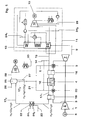
- Fig. 1 shows a syngas based low emission power according to the present invention.
- Air 1 is fed through a compressor 2 before the compressed air 3 is fed at least through a membrane/partial oxidation (POX) reactor 4.
- POX membrane/partial oxidation
- the membrane/POX reactor 4 After the membrane/POX reactor 4 the air is burned in a combustion chamber 5 together with hydrogen 6.
- the flue gases are then expanded in a turbine 7, which is driving the compressor 2 and producing electricity in a generator 8.
- the hot flue gases 9 are utilised in a heat recovery steam generator 10 producing steam for the bottoming steam cycle 11 and producing more power in a steam turbine 12 and electricity in a generator 13.
- natural gas 14 is being mixed with superheated intermediate pressure steam 15 and is then lead to the membrane/POX reactor 4.
- a medium temperature heat exchanger 16 to raise the temperature of the mixture of steam 15 and natural gas 14. This would flatten out the temperature profile in the membrane/POX reactor 4 and thus lower the temperature gradients in this. Since the temperature involved is not too high ( ⁇ 900°C), it might be possible to use a metal heat exchanger.
- oxygen is transferred through a membrane 18 from a first side to a second side and is partially oxidised (as well as reformed with steam) on the membrane 18 surface with the natural gas 14 by the following reactions: CH 4 + 0.5O 2 ⁇ 2H 2 + CO + 35.67 kJ/mol CH 4 + H 2 O ⁇ CO + 3H 2 - 205 kJ/mol CO + H 2 O ⁇ CO 2 +H 2 + 41.15 kJ/mol
- the three reactions combine to produce a mixture of H 2 , CO and CO 2 ; the overall heat balance and product mixture is dictated by the amount of oxygen (and endothermic reactions) that is present.
- the design of the membrane/POX reactor 4 is such that the overall process is autothermal, and the membrane temperature is of ca. 800 °C.
- the membrane/POX reactor 4 would be combined to both work as an oxygen transferring membrane and as well as doing the partial oxidation.
- One membrane type that can be used to separate the oxygen from the air is a so-called "Mixed Conducting Membrane” (MCM). These materials consist of complex crystalline structures, which incorporate oxygen ion vacancies (5-15%).
- the transport principle for oxygen transport through the membrane 18 is adsorption on the surface followed by decomposition into ions, which are transported through the membrane by sequentially occupying oxygen ion vacancies.
- the ion transport is counterbalanced by a flow of electrons in the opposite direction.
- the driving force is a difference in oxygen partial pressure between the permeate and retentate sides of the membrane 18.
- the transport process also requires high temperatures, i.e. > 700°C.
- the surfaces of the permeate side of the membrane 18 that containing the syngas 17 1
- catalytic material to promote the formation of synthesis gas 17 1 and, in particular, hydrogen.
- Catalyst materials used for autothermal reforming are Rh, Ru, Co, Fe or bimetallic combinations thereof (e.g. Co/Fe).
- the air stream from the low temperature heat exchanger 19 can then be lead to a catalytic burner 20 where the air is heated by means of catalytic combustion.
- the fuel for the catalytic burner 20 is either hydrogen 21 or natural gas 14. Use of hydrogen 21 is preferred to avoid producing CO 2 .
- the reason for using a catalytic burner 20 is to increase the average temperature in the membrane/POX reactor 4, increasing the oxygen flux through the membrane 18. Also, the temperature gradient in the reactor 4 will be lower and thus the thermal stresses for the reactor 4 will decrease.
- This catalytic burner 20 can also be used to help control process conditions within the MCM reactor during start up or to address instabilities within the membrane/POX reactor 4 associated with the autothermal reforming and potential catalyst deactivation.
- the temperature of the MCM reactor will be very sensitive to the amount of O 2 present and we could have some strange transients during start up. A quick reacting catalytic burner 4 running on H 2 could help for process control.
- the syngas 17 1 After the syngas 17 1 has been cooled down in the low temperature heat ex changer 19, the syngas 17 1 is then further cooled down in a CO shift reactor 22, lowering the temperature further to about 200-300°C. Depending on the chosen cooling temperature, water will condense out or not. Since a low temperature favours the CO shift reaction it might be wise to keep the temperature low. This will also lower the water consumption for the cycle since the condensed water 23 can be re-injected in the bottoming steam cycle 11.
- the medium used for the cooling is boiler feed water 24 1 , 24 2 from a bottoming steam and water cycle 11.
- the syngas 17 1 undergoes the following reaction: CO + H 2 O ⁇ H 2 + CO 2 + 41.15 kJ/mol
- the CO shift reactor 22 is in other words used to convert CO and water to CO 2 and more hydrogen. Also this reaction is mildly exothermic, leading to that some of the water condensed out during the cooling (or all water if the cooling temperature is high) is evaporated again, taking heat from the exothermic process described above.
- the syngas 17 2 consists ideally of H 2 , CO 2 and H 2 O. This syngas 17 2 is then lead to some kind of CO 2 absorption equipment 25, based on either chemical or physical absorption.
- the CO 2 removal rate in this kind of equipment is around 90 %.
- Low pressure steam 26 needed for the CO 2 removal is extracted from the steam turbine 12, and the condensed water 27 is lead back to the feed water tank of the steam cycle 11.
- the removed CO 2 28 is further compressed by means of inter-cooling in a compressor 29, producing liquid CO 2 30 that might be deposited or used in for instance enhanced oil recovery.
- the syngas 17 3 mainly consisting of H 2 , H 2 O and some remaining CO 2 is lead to a combustion chamber 5, to be burned together with air from the first side of the membrane/POX reactor 4.
- the water in the syngas 17 3 helps control the combustion temperature and thus lowers NO x formation.
- a part of the resulting syngas 17 3 comprising hydrogen 6 from the CO 2 removal equipment 25 can as well be burned in the catalytic burner 20.
Landscapes
- Chemical & Material Sciences (AREA)
- Engineering & Computer Science (AREA)
- Combustion & Propulsion (AREA)
- Organic Chemistry (AREA)
- Chemical Kinetics & Catalysis (AREA)
- General Engineering & Computer Science (AREA)
- Mechanical Engineering (AREA)
- Inorganic Chemistry (AREA)
- General Health & Medical Sciences (AREA)
- Health & Medical Sciences (AREA)
- Analytical Chemistry (AREA)
- Separation Using Semi-Permeable Membranes (AREA)
- Hydrogen, Water And Hydrids (AREA)
- Paper (AREA)
Claims (13)
- Procédé d'exploitation d'une centrale électrique à turbines à gaz comprenant les étapes suivantes:comprimer de l'air (1) dans au moins un compresseur (2),conduire l'air comprimé (3) dudit au moins un compresseur (2) à travers un premier côté d'un réacteur à membrane/oxydation partielle (4),conduire l'air en provenance du premier côté du réacteur à membrane/oxydation partielle (4) jusqu'à une chambre de combustion (5),brûler l'air avec de l'hydrogène (6), produisant de ce fait des gaz de fumée (9),dilater les gaz de fumée (9) dans une turbine à gaz (7) qui entraîne au moins un générateur (9),fournir du gaz naturel (14) mélangé avec de la vapeur (15) à un deuxième côté du réacteur à membrane/oxydation partielle (4), et convertir le gaz naturel (14) au moins en H2 et en CO, dans lequel l'oxygène est transféré à partir de l'air comprimé (3) à travers la membrane (18) du réacteur à membrane/oxydation partielle (4), et utiliser l'oxygène pour le procédé d'oxydation partielle du gaz naturel (14),fournir le gaz de synthèse obtenu (171) à un réacteur de conversion de CO (22), produisant de ce fait de l'H2 et convertissant une majeure partie du CO restant en CO2,fournir le gaz de synthèse obtenu (172) en provenance du réacteur de conversion de CO (22) à un équipement d'élimination de CO2 (25), éliminant de ce fait le CO2,conduire le gaz de synthèse obtenu (173) comprenant du H2 et de l'H2O en provenance de l'équipement d'élimination de CO2 (25) au moins jusqu'à la chambre de combustion (5).
- Procédé d'exploitation d'une centrale électrique à turbines à gaz selon la revendication 1, dans lequel le procédé comprend l'étape de combustion dans un brûleur catalytique (20) d'un combustible (6, 14) avec l'air comprimé (3) en provenance du compresseur (2), et de conduite des gaz obtenus du brûleur catalytique (20) au premier côté du réacteur à membrane/oxydation partielle (4).
- Procédé d'exploitation d'une centrale électrique à turbines à gaz selon la revendication 2, dans lequel le gaz naturel (14) et/ou une partie du gaz de synthèse obtenu (173) comprenant de l'hydrogène (6) en provenance de l'équipement d'élimination de CO2 (25) sont brûlés dans le brûleur catalytique (20).
- Procédé d'exploitation d'une centrale électrique à turbines à gaz selon la revendication 2, comprenant l'étape de combustion dans un brûleur catalytique (20) d'un combustible (6, 14) avec l'air comprimé (3) en provenance du compresseur (2), et de conduite des gaz obtenus du brûleur catalytique (20) au premier côté du réacteur à membrane/oxydation partielle (4) pendant le démarrage de la centrale électrique à turbines à gaz.
- Procédé d'exploitation d'une centrale électrique à turbines à gaz selon l'une quelconque des revendications 1 à 4, dans lequel le gaz de synthèse produit (171) qui arrive en provenance du deuxième côté du réacteur à membrane/oxydation partielle (4) est refroidi en utilisant l'air comprimé qui arrive en provenance du compresseur dans un échangeur de chaleur (19) avant que le gaz de synthèse (171) soit conduit au réacteur de conversion de CO (22).
- Procédé d'exploitation d'une centrale électrique à turbines à gaz selon l'une quelconque des revendications 1 à 4, dans lequel le gaz naturel (14) qui est mélangé à la vapeur (15) est chauffé en utilisant l'air comprimé qui arrive en provenance du premier côté du réacteur à membrane/oxydation partielle (4) dans un échangeur de chaleur (16) avant que le mélange soit conduit au réacteur à membrane/oxydation partielle (4).
- Procédé d'exploitation d'une centrale électrique à turbines à gaz selon l'une quelconque des revendications 1 à 6, dans lequel le CO2 extrait de l'équipement d'élimination de CO2 (25) est comprimé et liquéfié.
- Procédé d'exploitation d'une centrale électrique à turbines à gaz selon l'une quelconque des revendications 1 à 7, comprenant l'étape de conduite des gaz de fumée chauds (9) de la turbine à gaz (7) à un générateur de vapeur de récupération de chaleur (10), produisant de ce fait de la vapeur et dilatant la vapeur générée dans une turbine à vapeur (12).
- Centrale électrique à turbines à gaz, comprenant:au moins un compresseur (2),un réacteur à membrane/oxydation partielle (4) qui présente deux côtés de la membrane (18), le réacteur à membrane/oxydation partielle (4) étant connecté sur une extrémité du premier côté au compresseur (2),une chambre de combustion (5) qui est connectée sur la deuxième extrémité du premier côté au réacteur à membrane/oxydation partielle (4),une turbine à gaz (7) qui est connectée à la chambre de combustion (5),une ligne d'alimentation qui est connectée à une extrémité du deuxième côté du réacteur à membrane/oxydation partielle (4),un réacteur de conversion de CO (22) qui est connecté à une deuxième extrémité du deuxième côté du réacteur à membrane/oxydation partielle (4) par une ligne d'alimentation,un équipement d'élimination de CO2 qui est connecté au réacteur de conversion de CO (22), etune ligne d'alimentation au moins pour l'hydrogène (6) qui est connectée à la chambre de combustion (5).
- Centrale électrique à turbines à gaz selon la revendication 9, dans laquelle les surfaces de la membrane (18) qui sont connectées au deuxième côté du réacteur à membrane/oxydation partielle (4) sont revêtues d'un matériau catalytique.
- Centrale électrique à turbines à gaz selon la revendication 10, dans laquelle la membrane (18) est revêtue d'un matériau catalytique constitué de Rh, de Ru, de Co, de Fe ou de combinaisons bi-métalliques de ceux-ci.
- Centrale électrique à turbines à gaz selon l'une quelconque des revendications 9 à 11, dans laquelle, avant et/ou après le réacteur à membrane et/ou oxydation partielle (4), un échangeur de chaleur (16, 19) est agencé pour relier le conduit d'air après le compresseur (2) et/ou avant la chambre de combustion (5) sur le premier côté de la membrane (18) et la ligne d'alimentation avant et/ou après le deuxième côté de la membrane (18).
- Centrale électrique à turbines à gaz selon l'une quelconque des revendications 9 à 12, dans laquelle le brûleur catalytique (20) est disposé avant le réacteur à membrane/oxydation partielle (4) qui est connecté sur une extrémité du premier côté de la membrane (18) et est connecté au compresseur (2).
Priority Applications (1)
| Application Number | Priority Date | Filing Date | Title |
|---|---|---|---|
| EP03795991A EP1561010B1 (fr) | 2002-11-08 | 2003-11-03 | Centrale electrique a turbines a gaz et procede pour l'exploiter |
Applications Claiming Priority (6)
| Application Number | Priority Date | Filing Date | Title |
|---|---|---|---|
| US42468102P | 2002-11-08 | 2002-11-08 | |
| US424681P | 2002-11-08 | ||
| EP02405995 | 2002-11-19 | ||
| EP02405995 | 2002-11-19 | ||
| PCT/EP2003/050782 WO2004042200A1 (fr) | 2002-11-08 | 2003-11-03 | Centrale electrique a turbines a gaz et procede pour l'exploiter |
| EP03795991A EP1561010B1 (fr) | 2002-11-08 | 2003-11-03 | Centrale electrique a turbines a gaz et procede pour l'exploiter |
Publications (2)
| Publication Number | Publication Date |
|---|---|
| EP1561010A1 EP1561010A1 (fr) | 2005-08-10 |
| EP1561010B1 true EP1561010B1 (fr) | 2012-09-05 |
Family
ID=56290500
Family Applications (1)
| Application Number | Title | Priority Date | Filing Date |
|---|---|---|---|
| EP03795991A Expired - Lifetime EP1561010B1 (fr) | 2002-11-08 | 2003-11-03 | Centrale electrique a turbines a gaz et procede pour l'exploiter |
Country Status (6)
| Country | Link |
|---|---|
| US (1) | US7363764B2 (fr) |
| EP (1) | EP1561010B1 (fr) |
| AU (1) | AU2003298266A1 (fr) |
| CA (1) | CA2505354C (fr) |
| NO (1) | NO337677B1 (fr) |
| WO (1) | WO2004042200A1 (fr) |
Cited By (2)
| Publication number | Priority date | Publication date | Assignee | Title |
|---|---|---|---|---|
| DK178834B1 (en) * | 2016-03-15 | 2017-03-06 | Mogens Skou Nielsen | A system and method to generate power using dry ice |
| EP3428532A1 (fr) * | 2017-07-12 | 2019-01-16 | Linde Aktiengesellschaft | Procédé de fonctionnement d'un brûleur de claus |
Families Citing this family (103)
| Publication number | Priority date | Publication date | Assignee | Title |
|---|---|---|---|---|
| DE102005042176B4 (de) * | 2004-09-29 | 2014-08-28 | Alstom Technology Ltd. | Kraftwerksanlage und zugehöriges Betriebsverfahren |
| EP1643100B1 (fr) | 2004-09-29 | 2017-06-28 | Ansaldo Energia IP UK Limited | Centrale et méthode associée d'opération |
| NO20051895D0 (no) * | 2005-04-19 | 2005-04-19 | Statoil Asa | Fremgangsmate for produksjon av elektrisk energi og CO2 fra et hydrokarbon rastoff |
| US7650744B2 (en) * | 2006-03-24 | 2010-01-26 | General Electric Company | Systems and methods of reducing NOx emissions in gas turbine systems and internal combustion engines |
| WO2008014481A1 (fr) * | 2006-07-28 | 2008-01-31 | Rollins William S Iii | Centrale à cycle combiné à gazéication intégrée à haut rendement |
| EP2067937A2 (fr) * | 2007-08-27 | 2009-06-10 | Siemens Aktiengesellschaft | Procédé de fonctionnement d'une centrale électrique avec gazage intégré tout comme centrale électrique |
| US20090241551A1 (en) * | 2008-03-26 | 2009-10-01 | Air Liquide Process And Construction Inc. | Cogeneration of Hydrogen and Power |
| MY156350A (en) | 2008-03-28 | 2016-02-15 | Exxonmobil Upstream Res Co | Low emission power generation and hydrocarbon recovery systems and methods |
| MY153097A (en) | 2008-03-28 | 2014-12-31 | Exxonmobil Upstream Res Co | Low emission power generation and hydrocarbon recovery systems and methods |
| DE102008048062B3 (de) * | 2008-09-19 | 2010-04-08 | Forschungszentrum Jülich GmbH | IGCC-Kraftwerk mit Rauchgasrückführung und Spülgas |
| BRPI0920139A2 (pt) | 2008-10-14 | 2015-12-22 | Exxonmobil Upstream Res Co | sistema de combustão, método de controle de combustão, e, sistema de combustor. |
| EP2199547A1 (fr) * | 2008-12-19 | 2010-06-23 | Siemens Aktiengesellschaft | Générateur de vapeur pour récupérer la chaleur et procédé de fonctionnement amélioré d'un générateur de vapeur pour récupérer la chaleur |
| US9416728B2 (en) | 2009-02-26 | 2016-08-16 | 8 Rivers Capital, Llc | Apparatus and method for combusting a fuel at high pressure and high temperature, and associated system and device |
| US8596075B2 (en) | 2009-02-26 | 2013-12-03 | Palmer Labs, Llc | System and method for high efficiency power generation using a carbon dioxide circulating working fluid |
| US10018115B2 (en) | 2009-02-26 | 2018-07-10 | 8 Rivers Capital, Llc | System and method for high efficiency power generation using a carbon dioxide circulating working fluid |
| US8776531B2 (en) * | 2009-11-06 | 2014-07-15 | General Electric Company | Gas engine drives for gasification plants |
| CN102597418A (zh) | 2009-11-12 | 2012-07-18 | 埃克森美孚上游研究公司 | 低排放发电和烃采收系统及方法 |
| US8435326B2 (en) * | 2010-01-15 | 2013-05-07 | G.D.O. | Multi-stage process for removing CO2 relative to hydrogen from syngas streams |
| DE102010024429A1 (de) | 2010-06-21 | 2011-12-22 | Technische Universität München | CO2 freies IGCC Kraftwerk mit Heißgasreinigung und optimierter CO2 Abtrennung |
| EA029301B1 (ru) | 2010-07-02 | 2018-03-30 | Эксонмобил Апстрим Рисерч Компани | Интегрированные системы для получения со(варианты) и способ производства электроэнергии |
| AU2011271636B2 (en) | 2010-07-02 | 2016-03-17 | Exxonmobil Upstream Research Company | Low emission power generation systems and methods |
| CA2801494C (fr) | 2010-07-02 | 2018-04-17 | Exxonmobil Upstream Research Company | Combustion stoechiometrique d'air enrichi avec recirculation de gaz d'echappement |
| MY160832A (en) | 2010-07-02 | 2017-03-31 | Exxonmobil Upstream Res Co | Stoichiometric combustion with exhaust gas recirculation and direct contact cooler |
| DE102010049801A1 (de) | 2010-10-27 | 2012-05-03 | Technische Universität München | IGCC Kraftwerk mit Post Combustion CO2 Abtrennung mittels Carbonate Looping (ES-CL Cycle) |
| GB201018227D0 (en) * | 2010-10-28 | 2010-12-15 | Doosan Power Systems Ltd | Control system and method for power plant |
| TWI564474B (zh) | 2011-03-22 | 2017-01-01 | 艾克頌美孚上游研究公司 | 於渦輪系統中控制化學計量燃燒的整合系統和使用彼之產生動力的方法 |
| TWI563165B (en) | 2011-03-22 | 2016-12-21 | Exxonmobil Upstream Res Co | Power generation system and method for generating power |
| TWI563166B (en) | 2011-03-22 | 2016-12-21 | Exxonmobil Upstream Res Co | Integrated generation systems and methods for generating power |
| TWI593872B (zh) | 2011-03-22 | 2017-08-01 | 艾克頌美孚上游研究公司 | 整合系統及產生動力之方法 |
| KR102044831B1 (ko) | 2011-11-02 | 2019-11-15 | 8 리버스 캐피탈, 엘엘씨 | 전력 생산 시스템 및 상응하는 방법 |
| CN104428490B (zh) | 2011-12-20 | 2018-06-05 | 埃克森美孚上游研究公司 | 提高的煤层甲烷生产 |
| US8776532B2 (en) | 2012-02-11 | 2014-07-15 | Palmer Labs, Llc | Partial oxidation reaction with closed cycle quench |
| US9488100B2 (en) * | 2012-03-22 | 2016-11-08 | Saudi Arabian Oil Company | Apparatus and method for oxy-combustion of fuels in internal combustion engines |
| US9353682B2 (en) | 2012-04-12 | 2016-05-31 | General Electric Company | Methods, systems and apparatus relating to combustion turbine power plants with exhaust gas recirculation |
| US10273880B2 (en) | 2012-04-26 | 2019-04-30 | General Electric Company | System and method of recirculating exhaust gas for use in a plurality of flow paths in a gas turbine engine |
| US9784185B2 (en) | 2012-04-26 | 2017-10-10 | General Electric Company | System and method for cooling a gas turbine with an exhaust gas provided by the gas turbine |
| JP2013241923A (ja) * | 2012-05-23 | 2013-12-05 | Babcock Hitachi Kk | 炭素系燃料のガス化発電システム |
| US9708977B2 (en) | 2012-12-28 | 2017-07-18 | General Electric Company | System and method for reheat in gas turbine with exhaust gas recirculation |
| US9599070B2 (en) | 2012-11-02 | 2017-03-21 | General Electric Company | System and method for oxidant compression in a stoichiometric exhaust gas recirculation gas turbine system |
| US9869279B2 (en) | 2012-11-02 | 2018-01-16 | General Electric Company | System and method for a multi-wall turbine combustor |
| US9631815B2 (en) | 2012-12-28 | 2017-04-25 | General Electric Company | System and method for a turbine combustor |
| US9803865B2 (en) | 2012-12-28 | 2017-10-31 | General Electric Company | System and method for a turbine combustor |
| US9611756B2 (en) | 2012-11-02 | 2017-04-04 | General Electric Company | System and method for protecting components in a gas turbine engine with exhaust gas recirculation |
| US10107495B2 (en) | 2012-11-02 | 2018-10-23 | General Electric Company | Gas turbine combustor control system for stoichiometric combustion in the presence of a diluent |
| US10215412B2 (en) | 2012-11-02 | 2019-02-26 | General Electric Company | System and method for load control with diffusion combustion in a stoichiometric exhaust gas recirculation gas turbine system |
| US9574496B2 (en) | 2012-12-28 | 2017-02-21 | General Electric Company | System and method for a turbine combustor |
| US10100741B2 (en) | 2012-11-02 | 2018-10-16 | General Electric Company | System and method for diffusion combustion with oxidant-diluent mixing in a stoichiometric exhaust gas recirculation gas turbine system |
| US10208677B2 (en) | 2012-12-31 | 2019-02-19 | General Electric Company | Gas turbine load control system |
| US9581081B2 (en) | 2013-01-13 | 2017-02-28 | General Electric Company | System and method for protecting components in a gas turbine engine with exhaust gas recirculation |
| US9512759B2 (en) | 2013-02-06 | 2016-12-06 | General Electric Company | System and method for catalyst heat utilization for gas turbine with exhaust gas recirculation |
| TW201502356A (zh) | 2013-02-21 | 2015-01-16 | Exxonmobil Upstream Res Co | 氣渦輪機排氣中氧之減少 |
| US9938861B2 (en) | 2013-02-21 | 2018-04-10 | Exxonmobil Upstream Research Company | Fuel combusting method |
| RU2637609C2 (ru) | 2013-02-28 | 2017-12-05 | Эксонмобил Апстрим Рисерч Компани | Система и способ для камеры сгорания турбины |
| TW201500635A (zh) | 2013-03-08 | 2015-01-01 | Exxonmobil Upstream Res Co | 處理廢氣以供用於提高油回收 |
| WO2014137648A1 (fr) | 2013-03-08 | 2014-09-12 | Exxonmobil Upstream Research Company | Production d'énergie et récupération de méthane à partir d'hydrates de méthane |
| US20140250945A1 (en) | 2013-03-08 | 2014-09-11 | Richard A. Huntington | Carbon Dioxide Recovery |
| US9618261B2 (en) | 2013-03-08 | 2017-04-11 | Exxonmobil Upstream Research Company | Power generation and LNG production |
| US9617914B2 (en) | 2013-06-28 | 2017-04-11 | General Electric Company | Systems and methods for monitoring gas turbine systems having exhaust gas recirculation |
| US9835089B2 (en) | 2013-06-28 | 2017-12-05 | General Electric Company | System and method for a fuel nozzle |
| TWI654368B (zh) | 2013-06-28 | 2019-03-21 | 美商艾克頌美孚上游研究公司 | 用於控制在廢氣再循環氣渦輪機系統中的廢氣流之系統、方法與媒體 |
| US9631542B2 (en) | 2013-06-28 | 2017-04-25 | General Electric Company | System and method for exhausting combustion gases from gas turbine engines |
| US9587510B2 (en) | 2013-07-30 | 2017-03-07 | General Electric Company | System and method for a gas turbine engine sensor |
| US9903588B2 (en) | 2013-07-30 | 2018-02-27 | General Electric Company | System and method for barrier in passage of combustor of gas turbine engine with exhaust gas recirculation |
| US9951658B2 (en) | 2013-07-31 | 2018-04-24 | General Electric Company | System and method for an oxidant heating system |
| JP6250332B2 (ja) | 2013-08-27 | 2017-12-20 | 8 リバーズ キャピタル,エルエルシー | ガスタービン設備 |
| US10030588B2 (en) | 2013-12-04 | 2018-07-24 | General Electric Company | Gas turbine combustor diagnostic system and method |
| US9752458B2 (en) | 2013-12-04 | 2017-09-05 | General Electric Company | System and method for a gas turbine engine |
| US10227920B2 (en) | 2014-01-15 | 2019-03-12 | General Electric Company | Gas turbine oxidant separation system |
| US9915200B2 (en) | 2014-01-21 | 2018-03-13 | General Electric Company | System and method for controlling the combustion process in a gas turbine operating with exhaust gas recirculation |
| US9863267B2 (en) | 2014-01-21 | 2018-01-09 | General Electric Company | System and method of control for a gas turbine engine |
| US10079564B2 (en) | 2014-01-27 | 2018-09-18 | General Electric Company | System and method for a stoichiometric exhaust gas recirculation gas turbine system |
| EP2942495B1 (fr) | 2014-05-08 | 2018-10-10 | General Electric Technology GmbH | Installation oxy au charbon avec intégration de chaleur |
| EP2942497B1 (fr) | 2014-05-08 | 2018-10-31 | General Electric Technology GmbH | Intégration de chaleur pour système d'alimentation d'installation de chaudière oxy |
| PL2942494T3 (pl) | 2014-05-08 | 2020-03-31 | General Electric Technology Gmbh | Instalacja opalana mieszanką tlenowo-węglową z integracją ciepła |
| EP2942496B1 (fr) * | 2014-05-08 | 2018-10-10 | General Electric Technology GmbH | Installation de chauffage oxy avec unité de séparation d'air intégré de chaleur |
| US10047633B2 (en) | 2014-05-16 | 2018-08-14 | General Electric Company | Bearing housing |
| US10060359B2 (en) | 2014-06-30 | 2018-08-28 | General Electric Company | Method and system for combustion control for gas turbine system with exhaust gas recirculation |
| US9885290B2 (en) | 2014-06-30 | 2018-02-06 | General Electric Company | Erosion suppression system and method in an exhaust gas recirculation gas turbine system |
| US10655542B2 (en) | 2014-06-30 | 2020-05-19 | General Electric Company | Method and system for startup of gas turbine system drive trains with exhaust gas recirculation |
| TWI691644B (zh) | 2014-07-08 | 2020-04-21 | 美商八河資本有限公司 | 具改良效率之功率生產方法及系統 |
| WO2016040108A1 (fr) | 2014-09-09 | 2016-03-17 | 8 Rivers Capital, Llc | Production de dioxyde de carbone liquide à basse pression à partir d'un système de production d'énergie et procédé associé |
| US11231224B2 (en) | 2014-09-09 | 2022-01-25 | 8 Rivers Capital, Llc | Production of low pressure liquid carbon dioxide from a power production system and method |
| MA40950A (fr) | 2014-11-12 | 2017-09-19 | 8 Rivers Capital Llc | Systèmes et procédés de commande appropriés pour une utilisation avec des systèmes et des procédés de production d'énergie |
| US11686258B2 (en) | 2014-11-12 | 2023-06-27 | 8 Rivers Capital, Llc | Control systems and methods suitable for use with power production systems and methods |
| US10961920B2 (en) | 2018-10-02 | 2021-03-30 | 8 Rivers Capital, Llc | Control systems and methods suitable for use with power production systems and methods |
| US9819292B2 (en) | 2014-12-31 | 2017-11-14 | General Electric Company | Systems and methods to respond to grid overfrequency events for a stoichiometric exhaust recirculation gas turbine |
| US9869247B2 (en) | 2014-12-31 | 2018-01-16 | General Electric Company | Systems and methods of estimating a combustion equivalence ratio in a gas turbine with exhaust gas recirculation |
| US10788212B2 (en) | 2015-01-12 | 2020-09-29 | General Electric Company | System and method for an oxidant passageway in a gas turbine system with exhaust gas recirculation |
| US10094566B2 (en) | 2015-02-04 | 2018-10-09 | General Electric Company | Systems and methods for high volumetric oxidant flow in gas turbine engine with exhaust gas recirculation |
| US10253690B2 (en) | 2015-02-04 | 2019-04-09 | General Electric Company | Turbine system with exhaust gas recirculation, separation and extraction |
| US10316746B2 (en) | 2015-02-04 | 2019-06-11 | General Electric Company | Turbine system with exhaust gas recirculation, separation and extraction |
| US10267270B2 (en) | 2015-02-06 | 2019-04-23 | General Electric Company | Systems and methods for carbon black production with a gas turbine engine having exhaust gas recirculation |
| US10145269B2 (en) | 2015-03-04 | 2018-12-04 | General Electric Company | System and method for cooling discharge flow |
| US10480792B2 (en) | 2015-03-06 | 2019-11-19 | General Electric Company | Fuel staging in a gas turbine engine |
| MX2017016478A (es) | 2015-06-15 | 2018-05-17 | 8 Rivers Capital Llc | Sistema y metodo para la puesta en marcha de una instalacion de produccion de energia. |
| WO2017141186A1 (fr) | 2016-02-18 | 2017-08-24 | 8 Rivers Capital, Llc | Système et procédé de production d'électricité comprenant la méthanation |
| JP7001608B2 (ja) | 2016-02-26 | 2022-01-19 | 8 リバーズ キャピタル,エルエルシー | 電力プラントを制御するためのシステムおよび方法 |
| EP3512925B1 (fr) | 2016-09-13 | 2022-03-30 | 8 Rivers Capital, LLC | Système et procédé de production d'énergie par oxydation partielle |
| CN111094720B (zh) | 2017-08-28 | 2023-02-03 | 八河流资产有限责任公司 | 回热式超临界co2动力循环的低等级热优化 |
| PL3759322T3 (pl) | 2018-03-02 | 2024-03-18 | 8 Rivers Capital, Llc | Układy i sposoby wytwarzania energii z wykorzystaniem płynu roboczego z dwutlenku węgla |
| US11859517B2 (en) * | 2019-06-13 | 2024-01-02 | 8 Rivers Capital, Llc | Power production with cogeneration of further products |
| CN114901925A (zh) | 2019-10-22 | 2022-08-12 | 八河流资产有限责任公司 | 用于发电系统的热管理的控制方案和方法 |
| US11988114B2 (en) | 2022-04-21 | 2024-05-21 | Mitsubishi Power Americas, Inc. | H2 boiler for steam system |
Family Cites Families (7)
| Publication number | Priority date | Publication date | Assignee | Title |
|---|---|---|---|---|
| US4999995A (en) * | 1986-08-29 | 1991-03-19 | Enserch International Investments Ltd. | Clean electric power generation apparatus |
| GB2296255A (en) * | 1994-12-21 | 1996-06-26 | Jacobs Eng Ltd | Production of electricity and hydrogen |
| US5865878A (en) * | 1997-04-29 | 1999-02-02 | Praxair Technology, Inc. | Method for producing oxidized product and generating power using a solid electrolyte membrane integrated with a gas turbine |
| EP0939199B1 (fr) * | 1998-02-25 | 2004-03-31 | ALSTOM Technology Ltd | Centrale d'énergie et procédé de fonctionnement d'une centrale d'énergie avec un cycle de CO2 |
| EP0953748B1 (fr) * | 1998-04-28 | 2004-01-28 | ALSTOM (Switzerland) Ltd | Centrale d'énergie avec un cycle de CO2 |
| NO308401B1 (no) * | 1998-12-04 | 2000-09-11 | Norsk Hydro As | FremgangsmÕte for gjenvinning av CO2 som genereres i en forbrenningsprosess samt anvendelse derav |
| US6537465B2 (en) * | 2000-12-29 | 2003-03-25 | Praxair Technology, Inc. | Low pressure steam purged chemical reactor including an oxygen transport membrane |
-
2003
- 2003-11-03 WO PCT/EP2003/050782 patent/WO2004042200A1/fr not_active Ceased
- 2003-11-03 EP EP03795991A patent/EP1561010B1/fr not_active Expired - Lifetime
- 2003-11-03 CA CA2505354A patent/CA2505354C/fr not_active Expired - Fee Related
- 2003-11-03 AU AU2003298266A patent/AU2003298266A1/en not_active Abandoned
-
2005
- 2005-05-06 US US11/123,128 patent/US7363764B2/en not_active Expired - Fee Related
- 2005-06-08 NO NO20052767A patent/NO337677B1/no not_active IP Right Cessation
Cited By (2)
| Publication number | Priority date | Publication date | Assignee | Title |
|---|---|---|---|---|
| DK178834B1 (en) * | 2016-03-15 | 2017-03-06 | Mogens Skou Nielsen | A system and method to generate power using dry ice |
| EP3428532A1 (fr) * | 2017-07-12 | 2019-01-16 | Linde Aktiengesellschaft | Procédé de fonctionnement d'un brûleur de claus |
Also Published As
| Publication number | Publication date |
|---|---|
| US20050235650A1 (en) | 2005-10-27 |
| NO20052767L (no) | 2005-06-08 |
| CA2505354C (fr) | 2012-04-03 |
| EP1561010A1 (fr) | 2005-08-10 |
| US7363764B2 (en) | 2008-04-29 |
| WO2004042200A1 (fr) | 2004-05-21 |
| CA2505354A1 (fr) | 2004-05-21 |
| NO337677B1 (no) | 2016-06-06 |
| AU2003298266A1 (en) | 2004-06-07 |
Similar Documents
| Publication | Publication Date | Title |
|---|---|---|
| EP1561010B1 (fr) | Centrale electrique a turbines a gaz et procede pour l'exploiter | |
| US20230042457A1 (en) | Systems and methods for power production with integrated production of hydrogen | |
| US7703271B2 (en) | Cogeneration method and device using a gas turbine comprising a post-combustion chamber | |
| JP5268471B2 (ja) | ポリジェネレーションシステム | |
| US10597292B2 (en) | Process for generating power and hydrogen gas | |
| AU2001292544B2 (en) | Joint-cycle high-efficiency fuel cell system with power generating turbine | |
| EP1858803B1 (fr) | Procede de production d'hydrogene avec coproduction et capture de dioxyde de carbone | |
| EP1095691A2 (fr) | Méthode et dispositif pour la production de dioxide de carbon | |
| EP0916385A1 (fr) | Conducteur ionique à électrolyte solide pour la production à débits réglables de vapeur et d'oxygène | |
| US20030068260A1 (en) | Integrated flameless distributed combustion/membrane steam reforming reactor and zero emissions hybrid power system | |
| JP4059546B2 (ja) | 合成ガスおよび電気エネルギーを組み合わせて製造する方法 | |
| US20140284199A1 (en) | Water Purification Using Energy from a Steam-Hydrocarbon Reforming Process | |
| US7467519B2 (en) | Electricity and synthesis gas generation method | |
| Roses et al. | Comparison between fixed bed and fluidized bed membrane reactor configurations for PEM based micro-cogeneration systems | |
| US7163648B2 (en) | Method for manufacturing a hydrogen and nitrogen containing gas mixture | |
| KR100824082B1 (ko) | 흡열반응 수행을 위한 간접적 열원으로서 가열유체 수득방법 | |
| EP2865640B1 (fr) | Purification d'eau utilisant de l'énergie à partir d'un processus de reformage de vapeur d'hydrocarbures | |
| JP4232591B2 (ja) | 水素生産システム | |
| JP2002122030A (ja) | 電力と水素の併産設備 | |
| MXPA98009617A (en) | Ionic conductor of solid electrolyte with production of steam-to-oxygen regula |
Legal Events
| Date | Code | Title | Description |
|---|---|---|---|
| PUAI | Public reference made under article 153(3) epc to a published international application that has entered the european phase |
Free format text: ORIGINAL CODE: 0009012 |
|
| 17P | Request for examination filed |
Effective date: 20050426 |
|
| AK | Designated contracting states |
Kind code of ref document: A1 Designated state(s): AT BE BG CH CY CZ DE DK EE ES FI FR GB GR HU IE IT LI LU MC NL PT RO SE SI SK TR |
|
| AX | Request for extension of the european patent |
Extension state: AL LT LV MK |
|
| DAX | Request for extension of the european patent (deleted) | ||
| RBV | Designated contracting states (corrected) |
Designated state(s): DE GB |
|
| RIN1 | Information on inventor provided before grant (corrected) |
Inventor name: WINKLER, DIETER Inventor name: HOLMBERG, DANIEL Inventor name: GRIFFIN, TIMOTHY |
|
| GRAP | Despatch of communication of intention to grant a patent |
Free format text: ORIGINAL CODE: EPIDOSNIGR1 |
|
| RIN1 | Information on inventor provided before grant (corrected) |
Inventor name: HOLMBERG, DANIEL Inventor name: GRIFFIN, TIMOTHY Inventor name: WINKLER, DIETER |
|
| GRAS | Grant fee paid |
Free format text: ORIGINAL CODE: EPIDOSNIGR3 |
|
| GRAA | (expected) grant |
Free format text: ORIGINAL CODE: 0009210 |
|
| AK | Designated contracting states |
Kind code of ref document: B1 Designated state(s): DE GB |
|
| REG | Reference to a national code |
Ref country code: GB Ref legal event code: FG4D Ref country code: DE Ref legal event code: R081 Ref document number: 60342045 Country of ref document: DE Owner name: GENERAL ELECTRIC TECHNOLOGY GMBH, CH Free format text: FORMER OWNER: ALSTOM TECHNOLOGY LTD., BADEN, CH |
|
| REG | Reference to a national code |
Ref country code: DE Ref legal event code: R096 Ref document number: 60342045 Country of ref document: DE Effective date: 20121031 |
|
| PLBE | No opposition filed within time limit |
Free format text: ORIGINAL CODE: 0009261 |
|
| STAA | Information on the status of an ep patent application or granted ep patent |
Free format text: STATUS: NO OPPOSITION FILED WITHIN TIME LIMIT |
|
| 26N | No opposition filed |
Effective date: 20130606 |
|
| REG | Reference to a national code |
Ref country code: DE Ref legal event code: R097 Ref document number: 60342045 Country of ref document: DE Effective date: 20130606 |
|
| REG | Reference to a national code |
Ref country code: DE Ref legal event code: R082 Ref document number: 60342045 Country of ref document: DE Representative=s name: RUEGER | ABEL PATENT- UND RECHTSANWAELTE, DE Ref country code: DE Ref legal event code: R082 Ref document number: 60342045 Country of ref document: DE Representative=s name: RUEGER ABEL PATENTANWAELTE PARTGMBB, DE Ref country code: DE Ref legal event code: R082 Ref document number: 60342045 Country of ref document: DE Representative=s name: RUEGER, BARTHELT & ABEL, DE Ref country code: DE Ref legal event code: R081 Ref document number: 60342045 Country of ref document: DE Owner name: GENERAL ELECTRIC TECHNOLOGY GMBH, CH Free format text: FORMER OWNER: ALSTOM TECHNOLOGY LTD., BADEN, CH Ref country code: DE Ref legal event code: R082 Ref document number: 60342045 Country of ref document: DE Representative=s name: RUEGER ABEL PATENT- UND RECHTSANWAELTE, DE |
|
| PGFP | Annual fee paid to national office [announced via postgrant information from national office to epo] |
Ref country code: DE Payment date: 20161123 Year of fee payment: 14 Ref country code: GB Payment date: 20161128 Year of fee payment: 14 |
|
| REG | Reference to a national code |
Ref country code: DE Ref legal event code: R119 Ref document number: 60342045 Country of ref document: DE |
|
| GBPC | Gb: european patent ceased through non-payment of renewal fee |
Effective date: 20171103 |
|
| PG25 | Lapsed in a contracting state [announced via postgrant information from national office to epo] |
Ref country code: DE Free format text: LAPSE BECAUSE OF NON-PAYMENT OF DUE FEES Effective date: 20180602 |
|
| PG25 | Lapsed in a contracting state [announced via postgrant information from national office to epo] |
Ref country code: GB Free format text: LAPSE BECAUSE OF NON-PAYMENT OF DUE FEES Effective date: 20171103 |