EP1560743B1 - Connecting joint for shell elements - Google Patents
Connecting joint for shell elements Download PDFInfo
- Publication number
- EP1560743B1 EP1560743B1 EP03769460A EP03769460A EP1560743B1 EP 1560743 B1 EP1560743 B1 EP 1560743B1 EP 03769460 A EP03769460 A EP 03769460A EP 03769460 A EP03769460 A EP 03769460A EP 1560743 B1 EP1560743 B1 EP 1560743B1
- Authority
- EP
- European Patent Office
- Prior art keywords
- shell
- shell element
- vehicle body
- projections
- body according
- Prior art date
- Legal status (The legal status is an assumption and is not a legal conclusion. Google has not performed a legal analysis and makes no representation as to the accuracy of the status listed.)
- Expired - Lifetime
Links
Images
Classifications
-
- B—PERFORMING OPERATIONS; TRANSPORTING
- B62—LAND VEHICLES FOR TRAVELLING OTHERWISE THAN ON RAILS
- B62D—MOTOR VEHICLES; TRAILERS
- B62D25/00—Superstructure or monocoque structure sub-units; Parts or details thereof not otherwise provided for
- B62D25/02—Side panels
-
- B—PERFORMING OPERATIONS; TRANSPORTING
- B62—LAND VEHICLES FOR TRAVELLING OTHERWISE THAN ON RAILS
- B62D—MOTOR VEHICLES; TRAILERS
- B62D25/00—Superstructure or monocoque structure sub-units; Parts or details thereof not otherwise provided for
- B62D25/20—Floors or bottom sub-units
- B62D25/2009—Floors or bottom sub-units in connection with other superstructure subunits
- B62D25/2036—Floors or bottom sub-units in connection with other superstructure subunits the subunits being side panels, sills or pillars
-
- B—PERFORMING OPERATIONS; TRANSPORTING
- B62—LAND VEHICLES FOR TRAVELLING OTHERWISE THAN ON RAILS
- B62D—MOTOR VEHICLES; TRAILERS
- B62D27/00—Connections between superstructure or understructure sub-units
- B62D27/02—Connections between superstructure or understructure sub-units rigid
- B62D27/023—Assembly of structural joints
-
- B—PERFORMING OPERATIONS; TRANSPORTING
- B62—LAND VEHICLES FOR TRAVELLING OTHERWISE THAN ON RAILS
- B62D—MOTOR VEHICLES; TRAILERS
- B62D65/00—Designing, manufacturing, e.g. assembling, facilitating disassembly, or structurally modifying motor vehicles or trailers, not otherwise provided for
- B62D65/02—Joining sub-units or components to, or positioning sub-units or components with respect to, body shell or other sub-units or components
- B62D65/04—Joining preassembled modular units composed of sub-units performing diverse functions, e.g. engine and bonnet
Definitions
- the invention relates to a vehicle body made of a metallic material, formed in shell construction, interconnected shell elements, wherein each of two interconnected shell elements having a shell element at its the other shell element facing edge protrusions, which are inserted through formed in the other shell member through-openings.
- a connection technology for a vehicle body made of steel with shell elements for the bottom plate and the side walls with integrated side skirts is particularly suitable.
- vehicle bodies based on shell elements are a long established technique.
- Shell elite i.
- Application-specific shaped sheet metal elements mostly consisting of interconnected upper and lower shell, thereby fulfilling the function of an enveloping wall and at the same time a supporting component.
- Such manufactured vehicle bodies are characterized by a low weight and by compared to the profile-based space-frame design significantly reduced number of parts.
- a weak point in the shell construction is the connection of the shell elements underneath.
- two shell elements such as the bottom plate of a vehicle body and the associated vehicle side wall, connected to each other via formed on the bottom plate, bent edge portions which bear against the side wall and are connected to it cohesively, usually by welding.
- this type of connection is easy to implement, it does not meet the demands of today's rigidity, as it largely depends on the strength of the integral connection.
- a variety of additional reinforcement and stiffening plates are required, which increase the production cost considerably.
- connection nodes are known in various designs.
- US Patent Application Publication No. 2001/0000119 A1 and US Pat. No. 6,092,865 A each disclose a vehicle frame in space-frame construction based on hollow sections with connection nodes, in which the end regions of transverse or vertical supports for Connection with a vehicle longitudinal member through appropriately sized and aligned openings in the side or top of the longitudinal member inserted and connected by welding with this.
- connection nodes formed in this way are additionally secured by glued-on corner reinforcements in the form of gusset plates.
- connection nodes in a vehicle support frame with longitudinal and transverse supports configured as hollow profiles, in which the end regions of the Cross members are inserted through aligned openings arranged in the side rails.
- the connection is not made by welding, but by a force-locking manner by a tool inserted into the end-side open end region of the cross member, which spreads the end portion radially outwards and thus clamps it to the side member in the region of the opening.
- US Pat. No. 2,009,963 describes a substantially two-dimensional vehicle frame consisting of two longitudinal members and different cross members.
- the cross members are cut crosswise at their ends, so that they form longitudinally aligned, distributed over the circumference projections whose length slightly exceeds the wall thickness of the side members.
- the connection nodes between the longitudinal and transverse beams are designed such that in each case a cross member is inserted so far with its one end into a trained on its circumference, formed on the inside of the longitudinal member opening that the projections arranged by aligned to the opening in the Outside of the side rail molded slots are inserted and slightly protrude beyond the outside.
- the longitudinal member and the respective cross member are welded together at the protruding projections on the outside of the longitudinal member and in the region of the opening on the inside thereof.
- the supernatants of the first shell element are introduced into blind grooves of the second shell element and fixed there with the aid of adhesives.
- the first shell element is formed as a stiffening sheet. It serves to increase the rigidity between a connection of two body panels.
- the invention is therefore an object of the invention to provide a vehicle body of the type mentioned with a high rigidity, which can be realized without much manufacturing effort.
- connection node of the type mentioned above in that on the supernatants on both sides of the other shell member each have a sleeve, consisting of a sleeve portion and a collar formed at one end thereof, and that the collar of the sleeve with the the insertion opening surrounding area of the other shell element and the Sleeve section are connected to the supernatant cohesively.
- the central advantage of this construction is that the rigidity of a vehicle body formed from such connected shell elements in comparison to a vehicle body with only connected by material connection shell elements is much larger by passing through the projections provided on the one shell element protrusions through the through-openings formed in the other shell element.
- well-usable attachment zones for a cohesive connection of the interconnected shell elements are realized by the cuffs sitting on the supernatants.
- connection technology according to the invention for vehicle bodies in shell construction in which several protrusions are pushed through by the shell element molded through openings in the side wall, the advantages of space-frame technology in terms of body rigidity with the particular advantages of the shell construction, namely the low weight and the greatly reduced number of parts, connect in an optimal manner, so that as a result a body is obtained, which is superior in all relevant characteristics of bodies in conventional design.
- the insertion openings formed in the other shell element have an oversize relative to the dimensions of the projections of the one shell element.
- several, sometimes far apart supernatants, via which it is connected to the vehicle side wall and possibly to other shell elements via the connection node according to the invention which makes particularly high demands on a dimensionally stable production.
- larger manufacturing tolerances can be allowed.
- the cohesive connection is designed as a welded joint.
- this is designed as a laser weld. This results in an improved durability of the construction and a higher rigidity. If this laser weld also formed as a circumferential seam, a particularly tight connection between the sleeve and the other shell element can be achieved, whereby, for example, the Passage of moisture at this point is minimized.
- a further advantageous embodiment of the vehicle body according to the invention comprises shell elements which are designed as a base plate and side walls, and is characterized in that the side walls have integrated rocker sills, in which the push-through openings are provided.
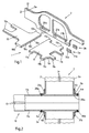
- the two-part base plate 1 of FIG. 1 is designed in shell construction of metallic materials.
- metallic materials are particularly suitable steel, but also other materials, such as. Aluminum.
- the bottom plate 1 consists of a rear part 10 and a front part 11, which are each composed of an upper shell 10o and 11o and a lower shell 10u and 11u, respectively.
- the remaining gap between the two parts 10, 11 is closed, for example, by another, not shown, shell element.
- a vehicle side wall 2 is also shown, which comprises a arranged below the recesses for the vehicle side doors side skirts 2s and is also designed in steel shell construction with an outer shell 2a and an inner shell 2i.
- the upper and lower shells 10o, 11o, 10u, 11u of the front and rear parts 10, 11 of the bottom plate 1 and the outer and inner shell 2a, 2i of the side wall 2 are weld points, not shown, at their bent peripheral edges 10r, 11r, 2r interconnected (see Fig. 2).
- the rear part 10 of the bottom plate 1 has two projections 10a extending in the direction of the rear of the vehicle and two projections 10b pointing outwards.
- the front part 11 of the bottom plate 1 has two projections 11c pointing in the direction of the vehicle front, as well as two pairs of projections pointing outwards in each case 11a and 11b on.
- the inner dimensions of the openings 20a, 21a, 21b are chosen such that they have an oversize relative to the outer dimensions of the respectively associated projections 10b, 11a, 11b.
- two cuffs 3a, 3b are further shown in particular of steel, each comprising a sleeve portion 30a, 30b and each having a collar 31a, 31b formed at one end thereof.
- the inner dimensions of the sleeve sections 30a, 30b correspond to the outer dimensions of the supernatant 11b assigned to them, so that they sit without gaps on the projection 11b (see Fig. 2).
- a further pair of sleeves are provided, which for reasons of clarity are not shown in FIG.
- Fig. 2 the connecting nodes formed by the parts 10, 11 of the bottom plate 1 and the side wall 2 are shown on the example of the supernatant 11b of the front part 11 of the bottom plate 1 and the opening 21b in the side sill 2s of the side wall 2.
- the supernatant 11b is pushed through the opening 21b in the side sill 2s. Since the inner dimensions of the opening 21b are designed to be oversized relative to the outer dimensions of the projection 11b, the upper and lower shells 11o, 11u are not gap-free at the edges of the opening 21b, as can be seen in FIG.
- the collar 3a and 3b continue to sit on the projection 11b on either side of the side wall 2.
- the projection 11b is preferably pushed so far through the opening 21b, that the sleeve portion 30b of the sleeve 3b is flush with the front edge of the supernatant 11b.
- the collars are connected to the supernatant 11b as well as to the side wall 2 by a material fit, preferably by means of a welded connection.
- the collars 31a, 31b of the collars 3a, 3b are connected to the side wall 2 by means of a laser weld seam 4b and the connection of the sleeve sections 30a, 30b to the projection 11b via a spot welding connection 4a.
Landscapes
- Engineering & Computer Science (AREA)
- Chemical & Material Sciences (AREA)
- Combustion & Propulsion (AREA)
- Transportation (AREA)
- Mechanical Engineering (AREA)
- Manufacturing & Machinery (AREA)
- Body Structure For Vehicles (AREA)
- Connection Of Plates (AREA)
- Coupling Device And Connection With Printed Circuit (AREA)
- Control Of Motors That Do Not Use Commutators (AREA)
- Joining Of Building Structures In Genera (AREA)
Abstract
Description
Die Erfindung betrifft eine Fahrzeugkarosserie aus einem metallischen Werkstoff, mit in Schalenbauweise ausgebildeten, miteinander verbundenen Schalenelementen, wobei von jeweils zwei miteinander verbundenen Schalenelementen das eine Schalenelement an seinem dem anderen Schalenelement zugewandten Rand Überstände aufweist, die durch im anderen Schalenelement ausgebildete Durchstecköffnungen gesteckt sind. Besonders geeignet ist eine solche Verbindungstechnik für eine Fahrzeugkarosserie aus Stahl mit Schalenelementen für die Bodenplatte und die Seitenwände mit integrierten Seitenschwellern.The invention relates to a vehicle body made of a metallic material, formed in shell construction, interconnected shell elements, wherein each of two interconnected shell elements having a shell element at its the other shell element facing edge protrusions, which are inserted through formed in the other shell member through-openings. Particularly suitable is such a connection technology for a vehicle body made of steel with shell elements for the bottom plate and the side walls with integrated side skirts.
Bei der Fertigung von Fährzeugkarosserien auf der Basis von Schalenelementen handelt es um eine seit langem etablierte Technik. Schalenelemerite, d.h. anwendungsspezifisch geformte Blechelemente zumeist bestehend aus miteinander verbundener Ober- und Unterschale, erfüllen dabei die Funktion einer umhüllenden Wandung und zugleich die eines tragenden Bauteils. Derartig hergestellte Fahrzeugkarosserien zeichnen sich durch ein geringes Gewicht sowie durch eine im Vergleich zu der auf Profilen basierenden Space-Frame-Bauweise deutlich verringerte Teilezahl aus.The production of vehicle bodies based on shell elements is a long established technique. Shell elite, i. Application-specific shaped sheet metal elements mostly consisting of interconnected upper and lower shell, thereby fulfilling the function of an enveloping wall and at the same time a supporting component. Such manufactured vehicle bodies are characterized by a low weight and by compared to the profile-based space-frame design significantly reduced number of parts.
Einen Schwachpunkt bei der Schalenbauweise bildet die Verbindung der Schalenelemente untereiriander. In herkömmlicher Weise sind zwei Schalenelemente, beispielsweise die Bodenplatte einer Fahrzeugkarosserie und die zugehörige Fahrzeugseitenwand, miteinander über an der Bodenplatte ausgebildete, umgebogene Randbereiche verbunden, die an der Seitenwand anliegen und mit ihr stoffschlüssig, in der Regel durch Schweißen, verbunden sind. Diese Art der Anbindung ist zwar einfach zu -realisieren, bietet jedoch eine heutigen Anforderungen nicht mehr entsprechende Steifigkeit, da sie maßgeblich von der Festigkeit der stoffschlüssigen Verbindung abhängt. Darüber hinaus sind eine Vielzahl von zusätzlichen Verstärkungs- und Versteifungsblechen erforderlich, die den Fertigungsaufwand erheblich erhöhen.A weak point in the shell construction is the connection of the shell elements underneath. In a conventional manner, two shell elements, such as the bottom plate of a vehicle body and the associated vehicle side wall, connected to each other via formed on the bottom plate, bent edge portions which bear against the side wall and are connected to it cohesively, usually by welding. Although this type of connection is easy to implement, it does not meet the demands of today's rigidity, as it largely depends on the strength of the integral connection. In addition, a variety of additional reinforcement and stiffening plates are required, which increase the production cost considerably.
Aus dem Stand der Technik sind Verbindungsknoten in verschiedenen Ausführungen bekannt.From the prior art connection nodes are known in various designs.
So ist in der US-Patentanmeldung mit der Veröffentlichungsnummer 2001/0000119 A1 und in der US-Patentschrift 6,092,865 A jeweils ein Fahrzeugtragrahmen in Space-Frame-Bauweise auf Basis von Hohlprofilen mit Verbindungsknoten beschrieben, bei welchen die Endbereiche von Quer- bzw. Vertikalträgern zur Verbindung mit einem Fahrzeuglängsträger durch entsprechend dimensionierte und miteinander fluchtend angeordnete Öffnungen in der Seite bzw. Oberseite des Längsträgers durchgesteckt und durch Schweißen mit diesem verbunden sind. Im Falle der US 6,092,865 A sind die derart ausgebildeten Verbindungsknoten zusätzlich durch aufgeklebte Eckversteifungen in Form von Knotenblechen gesichert.For example, US Patent Application Publication No. 2001/0000119 A1 and US Pat. No. 6,092,865 A each disclose a vehicle frame in space-frame construction based on hollow sections with connection nodes, in which the end regions of transverse or vertical supports for Connection with a vehicle longitudinal member through appropriately sized and aligned openings in the side or top of the longitudinal member inserted and connected by welding with this. In the case of US Pat. No. 6,092,865 A, the connection nodes formed in this way are additionally secured by glued-on corner reinforcements in the form of gusset plates.
In der Patentschrift US 5,848,469 A ist ein Verfahren zur Herstellung von Verbindungsknoten in einem Fahrzeugtragrahmen mit als Hohlprofile ausgebildeten Längs- und Querträgern angegeben, bei dem die Endbereiche der Querträger durch miteinander fluchtend angeordnete Öffnungen in den Längsträgern durchgesteckt sind. Die Verbindung erfolgt hierbei jedoch nicht durch Schweißen, sondern kraftschlüssig durch ein in den stirnseitig offenen Endbereich der Querträger eingeführtes Werkzeug, welches den Endbereich radial nach außen spreizt und ihn somit mit dem Längsträger im Bereich der Öffnung verklammert.The patent US Pat. No. 5,848,469 A specifies a method for producing connection nodes in a vehicle support frame with longitudinal and transverse supports configured as hollow profiles, in which the end regions of the Cross members are inserted through aligned openings arranged in the side rails. In this case, however, the connection is not made by welding, but by a force-locking manner by a tool inserted into the end-side open end region of the cross member, which spreads the end portion radially outwards and thus clamps it to the side member in the region of the opening.
In der US-Patentschrift 2,009,963 schließlich ist ein im wesentlichen zweidimensionaler Fahrzeugrahmen, bestehend aus zwei Längsträgern und verschiedenen Querträgern, beschrieben. Die Querträger sind an ihren Enden kreuzweise eingeschnitten, so dass sie längs ausgerichtete, über den Umfang verteilte vorsprünge ausbilden, deren Länge die Wandstärke der Längsträger geringfügig übersteigt. Die Verbindungsknoten zwischen Längs- und Querträgern sind derart ausgebildet, dass jeweils ein Querträger mit seinem einen Ende in eine an seinen Umfang angepaßte, auf der Innenseite der Längsträger ausgebildete Öffnung so weit eingesteckt ist, dass die Vorsprünge durch zu der Öffnung fluchtend angeordnete, in die Außenseite der Längsträger eingeformte Schlitze durchgesteckt sind und über die Außenseite geringfügig hinausragen. Der Längsträger und der jeweilige Querträger sind an den überstehenden Vorsprüngen an der Außenseite des Längsträgers und im Bereich der Öffnung an dessen Innenseite miteinander verschweißt.Finally, US Pat. No. 2,009,963 describes a substantially two-dimensional vehicle frame consisting of two longitudinal members and different cross members. The cross members are cut crosswise at their ends, so that they form longitudinally aligned, distributed over the circumference projections whose length slightly exceeds the wall thickness of the side members. The connection nodes between the longitudinal and transverse beams are designed such that in each case a cross member is inserted so far with its one end into a trained on its circumference, formed on the inside of the longitudinal member opening that the projections arranged by aligned to the opening in the Outside of the side rail molded slots are inserted and slightly protrude beyond the outside. The longitudinal member and the respective cross member are welded together at the protruding projections on the outside of the longitudinal member and in the region of the opening on the inside thereof.
Allen Verbindungsknoten der zitierten Druckschriften ist gemeinsam, dass sie ausschließlich für zwei- und dreidimensionale Fahrzeugtragrahmen aus Hohlprofilen geeignet sind, bei denen ein Hohlprofil mit seiner Stirnseite vollständig in ein anderes eingeschoben bzw. durch dieses durchgeschoben wird. Eine einfache Übertragung der aufgezeigten technischen Lösungen auf Fahrzeugkarosserien in Schalenbauweise ist somit nicht möglich, da diese auf flächigen, d.h. zweidimensional ausgedehnten, Schalenelementen basieren, so dass einfache Einstecklösungen, wie sie im vorgenannten Stand der Technik beschrieben sind, nicht anwendbar sind. Ferner ist aus der US 5,297,836 A, die die Merkmale des Oberbegriffs des Anspruchs 1 offenbart, eine Fahrzeugkarosserie bekannt, die aus gefügten, flachen Schalenelementen gebildet ist. Ein erstes Schalenelement weist dabei überstände auf. Das mit dem ersten Schalenelement zu fügende zweite Schalenelement weist dazu korrespondierende Sacknuten auf. Zum Fügen der Schalenelemente werden die Überstände des ersten Schalenelements in Sacknuten des zweiten Schalenelementes eingeführt und dort mit Hilfe von Klebern befestigt. Gemäß diesem Stand der Technik ist das erste Schalenelement als Versteifungsblech gebildet. Es dient zur Erhöhung der Steifigkeit zwischen einer Verbindung von zwei Karosserieblechen.All connection nodes of the cited documents has in common that they are only suitable for two- and three-dimensional vehicle support frame made of hollow sections, in which a hollow profile is fully inserted with its front side in another or pushed through this. A simple transmission The technical solutions shown on vehicle bodies in shell construction is therefore not possible because they are based on flat, ie two-dimensionally extended, shell elements, so that simple plug-in solutions, as described in the aforementioned prior art, are not applicable. Further, from US 5,297,836 A, which discloses the features of the preamble of
Der Erfindung liegt daher die Aufgabe zugrunde, eine Fahrzeugkarosserie der eingangs genannten Art mit einer hohen Steifigkeit zu schaffen, die ohne großen fertigungstechnischen Aufwand realisiert werden kann.The invention is therefore an object of the invention to provide a vehicle body of the type mentioned with a high rigidity, which can be realized without much manufacturing effort.
Diese Aufgabe wird mit einem Verbindungsknoten der eingangs genannten Art dadurch gelöst, dass auf den Überständen auf beiden Seiten des anderen Schalenelementes jeweils eine Manschette, bestehend aus einem Hülsenabschnitt und einem an dessen einem Ende ausgebildeten Kragen, sitzt, und dass der Kragen der Manschette mit dem die Durchstecköffnung umgebenden Bereich des anderen Schalenelementes und der Hülsenabschnitt mit dem Überstand stoffschlüssig verbunden sind.This object is achieved with a connection node of the type mentioned above in that on the supernatants on both sides of the other shell member each have a sleeve, consisting of a sleeve portion and a collar formed at one end thereof, and that the collar of the sleeve with the the insertion opening surrounding area of the other shell element and the Sleeve section are connected to the supernatant cohesively.
Der zentrale Vorteil dieser Konstruktion liegt darin, dass durch das Durchstecken der an dem einen Schalenelement vorgesehenen Überstände durch die im anderen Schalenelement ausgebildeten Durchstecköffnungen die Steifigkeit einer aus derart verbundenen Schalenelementen gebildeten Fahrzeugkarosserie im Vergleich zu einer Fahrzeugkarosserie mit ausschließlich durch Stoffschluß verbundenen Schalenelementen wesentlich größer ist. Hinzu kommt, dass durch die auf den Überständen sitzenden Manschetten gut nutzbare Anbindungszonen für eine stoffschlüssige Verbindung der miteinander verbundenen Schalenelemente verwirklicht sind. Mit der erfindungsgemäßen Verbindungstechnik für Fahrzeugkarosserien in Schalenbauweise, bei der von dem Schalenelement mehrere Überstände durch in der Seitenwand eingeformte Durchstecköffnungen durchgesteckt werden, lassen sich die Vorzüge der Space-Frame-Technologie hinsichtlich der Karosseriesteifigkeit mit den besonderen Vorteilen der Schalenbauweise, nämlich dem geringen Gewicht und der stark reduzierten Teilezahl, in optimaler Weise verbinden, so dass im Ergebnis eine Karosserie erhalten wird, die in allen relevanten Merkmalen Karosserien in herkömmlicher Bauart überlegen ist.The central advantage of this construction is that the rigidity of a vehicle body formed from such connected shell elements in comparison to a vehicle body with only connected by material connection shell elements is much larger by passing through the projections provided on the one shell element protrusions through the through-openings formed in the other shell element. In addition, well-usable attachment zones for a cohesive connection of the interconnected shell elements are realized by the cuffs sitting on the supernatants. With the connection technology according to the invention for vehicle bodies in shell construction, in which several protrusions are pushed through by the shell element molded through openings in the side wall, the advantages of space-frame technology in terms of body rigidity with the particular advantages of the shell construction, namely the low weight and the greatly reduced number of parts, connect in an optimal manner, so that as a result a body is obtained, which is superior in all relevant characteristics of bodies in conventional design.
Nach einer bevorzugten Ausführungsform der Erfindung weisen die in dem anderen Schalenelement ausgebildeten Durchstecköffnungen relativ zu den Abmessungen der Überstände des einen Schalenelementes ein Übermaß auf. Hierbei wird berücksichtigt, dass z.B. die Bodenplatte eines Fahrzeuges als groß dimensioniertes Schalenelement vielfach mehrere, teilweise weit auseinander liegende Überstände aufweist, über welche sie an die Fahrzeugseitenwand und ggf. an weitere Schalenelemente über den erfindungsgemäßen Verbindungsknoten angebunden ist, was besonders hohe Anforderungen an eine maßhaltige Fertigung stellt. Im Falle von relativ zu den Abmessungen der Überstände mit Übermaß ausgebildeten Öffnungen in den Seitenschwellern können somit größere Fertigungstoleranzen zugelassen werden.According to a preferred embodiment of the invention, the insertion openings formed in the other shell element have an oversize relative to the dimensions of the projections of the one shell element. This takes into account that, for example, the bottom plate of a vehicle as a large-sized shell element In many cases, several, sometimes far apart supernatants, via which it is connected to the vehicle side wall and possibly to other shell elements via the connection node according to the invention, which makes particularly high demands on a dimensionally stable production. In the case of relative to the dimensions of the protrusions formed with oversize openings in the side skirts thus larger manufacturing tolerances can be allowed.
Hinsichtlich einer unter fertigungstechnischen Gesichtspunkten einfachen Realisierbarkeit ist es zweckmäßig, wenn die stoffschlüssige Verbindung als Schweißverbindung ausgebildet ist. Im Falle der Schweißverbindung zwischen Manschette und dem anderen Schalenelement ist es vorteilhaft, wenn diese als Laserschweißnaht ausgebildet ist. Dadurch ergibt sich ein verbessertes Betriebsfestigkeitsverhalten der Konstruktion sowie eine höhere Steifigkeit. Ist diese Laserschweißnaht zudem als umlaufende Naht ausgebildet, läßt sich eine besonders dichte Verbindung zwischen der Manschette und dem anderen Schalenelement erzielen, wodurch beispielsweise der Durchtritt von Feuchtigkeit an dieser Stelle minimiert wird.With regard to a manufacturing feasibility simple feasibility, it is expedient if the cohesive connection is designed as a welded joint. In the case of the welded connection between the sleeve and the other shell element, it is advantageous if this is designed as a laser weld. This results in an improved durability of the construction and a higher rigidity. If this laser weld also formed as a circumferential seam, a particularly tight connection between the sleeve and the other shell element can be achieved, whereby, for example, the Passage of moisture at this point is minimized.
Im Falle der Schweißverbindung zwischen Manschette und dem Überstand des einen Schalenelementes ist die Ausführung mittels Punktschweißens sinnvoll. Dieses Schweißverfahren läßt sich besonders leicht automatisieren und erlaubt zudem die Nutzung bestehender Anlagen, was zur Senkung der Fertigungskosten beiträgt.In the case of the welded connection between the sleeve and the supernatant of the one shell element, the execution by means of spot welding makes sense. This welding process is particularly easy to automate and also allows the use of existing equipment, which contributes to the reduction of manufacturing costs.
Eine weitere vorteilhafte Ausführungsform der erfindungsgemäßen Fahrzeugkarosserie umfaßt Schalenelemente, die als Bodenplatte und Seitenwände ausgebildet sind, und ist dadurch gekennzeichnet, dass die Seitenwände integrierte Bodenschweller aufweisen, in denen die Durchstecköffnungen vorgesehen sind. Durch diese Lösung läßt sich eine Karosserie mit Verbindungsknoten außerordentlich hoher Steifigkeit realisieren, da hierbei das als Bodenplatte ausgebildete Schalenelement mit seinen Überständen in ein ohnehin besonders versteiftes Karosserieteil eingreift.A further advantageous embodiment of the vehicle body according to the invention comprises shell elements which are designed as a base plate and side walls, and is characterized in that the side walls have integrated rocker sills, in which the push-through openings are provided. By this solution, a body can be realized with connection nodes exceptionally high rigidity, since in this case engages the trained as a bottom plate shell element with its supernatants in an already particularly stiffened body part.
Im folgenden wird die Erfindung anhand einer ein Ausführungsbeispiel darstellenden Zeichnung erläutert. Im einzelnen zeigen:
- Fig. 1
- eine zweiteilige Bodenplatte und eine Fahrzeugseitenwand in Schalenbauweise aus metallischen Werkstoffen, sowie zwei Manschetten in perspektivischer Ansicht und
- Fig. 2
- den Verbindungsknoten zwischen Bodenplatte und Seitenwand im geschnittener Ansicht.
- Fig. 1
- a two-piece base plate and a vehicle side wall in shell construction of metallic materials, and two cuffs in perspective view and
- Fig. 2
- the connection node between the bottom plate and side wall in the sectional view.
Die zweiteilige Bodenplatte 1 gemäß Fig. 1 ist in Schalenbauweise aus metallischen Werkstoffen ausgeführt. Als metallische Werkstoffe eignen sich insbesondere Stahl, aber auch andere Werkstoffe, wie z.B. Aluminium. Die Bodenplatte 1 besteht aus einem hinteren Teil 10 und einem vorderen Teil 11, welche jeweils aus einer oberen Schale 10o bzw. 11o und einer unteren Schale 10u bzw. 11u zusammengesetzt sind. Die zwischen den beiden Teilen 10, 11 verbleibende Lücke wird beispielsweise durch ein weiteres, nicht dargestelltes Schalenelement geschlossen. In Fig. 1 ist ebenfalls eine Fahrzeugseitenwand 2 dargestellt, die einen unterhalb der Aussparungen für die Fahrzeugseitentüren angeordneten Seitenschweller 2s umfaßt und ebenfalls in Stahl-Schalenbauweise mit einer äußeren Schale 2a und einer inneren Schale 2i ausgeführt ist. Die oberen und unteren Schalen 10o, 11o, 10u, 11u des vorderen und hinteren Teiles 10, 11 der Bodenplatte 1 sowie die äußere und innere Schale 2a, 2i der Seitenwand 2 sind über nicht dargestellte Schweißpunkte an ihren umgebogenen umlaufenden Rändern 10r, 11r, 2r miteinander verbunden (s. Fig. 2).The two-
Der hintere Teil 10 der Bodenplatte 1 weist zwei sich in Richtung des Fahrzeughecks erstreckende Überstände 10a sowie zwei nach außen weisende Überstände 10b auf. Entsprechend weist der vordere Teil 11 der Bodenplatte 1 zwei in Richtung der Fahrzeugfront weisende Überstände 11c sowie zwei Paare jeweils nach außen weisender Überstände 11a und 11b auf. Im Seitenschweller 2s der Fahrzeugseitenwand 2 sind drei rechteckige, durch die innere und äußere Schale 2i, 2a durchgehende Öffnungen 20a, 21a, 21b eingeformt, durch die die in Richtung der Seitenwand 2 weisenden Überstände 10b, 11a, 11b des hinteren und vorderen Teiles 10, 11 der Bodenplatte 1 durchgesteckt werden können. Dabei sind die Innenabmessungen der Öffnungen 20a, 21a, 21b derart gewählt, dass sie ein Übermaß gegenüber den Außenabmessungen der ihnen jeweils zugeordneten Überstände 10b, 11a, 11b aufweisen.The
In Fig. 1 sind weiterhin zwei Manschetten 3a, 3b insbesondere aus Stahl abgebildet, welche jeweils einen Hülsenabschnitt 30a, 30b und jeweils einen an dessen einem Ende ausgebildeten Kragen 31a, 31b umfassen. Die Innenabmessungen der Hülsenabschnitte 30a, 30b entsprechen dabei den Außenabmessungen des ihnen zugeordneten Überstandes 11b, so dass sie spaltfrei auf dem Überstand 11b sitzen (s. Fig. 2). Für die Überstände 10b und 11a sind jeweils ein weiteres Paar von Manschetten vorgesehen, die jedoch aus Gründen der Übersichtlichkeit in Fig. 1 nicht abgebildet sind.In Fig. 1, two
In Fig. 2 sind die durch die Teile 10, 11 der Bodenplatte 1 und die Seitenwand 2 gebildeten Verbindungsknoten am Beispiel des Überstandes 11b des vorderen Teils 11 der Bodenplatte 1 und der Öffnung 21b im Seitenschweller 2s der Seitenwand 2 dargestellt.In Fig. 2, the connecting nodes formed by the
Wie in Fig. 2 gezeigt, ist der Überstand 11b durch die Öffnung 21b im Seitenschweller 2s durchgeschoben. Da die Innenabmessungen der Öffnung 21b gegenüber den Außenabmessungen des Überstandes 11b mit Übermaß ausgelegt sind, liegen die obere und untere Schale 11o, 11u nicht spaltfrei an den Rändern der Öffnung 21b an, wie in Fig. 2 erkennbar ist. Auf dem Überstand 11b sitzen weiterhin die Manschetten 3a und 3b beiderseits der Seitenwand 2. Dabei liegen der Kragen 31a der Manschette 3a an der inneren Schale 2i und der Kragen 31b der Manschette 3b an der äußeren Schale 2a an. Der Überstand 11b ist vorzugsweise so weit durch die Öffnung 21b durchgeschoben, dass der Hülsenabschnitt 30b der Manschette 3b bündig mit dem stirnseitigen Rand des Überstandes 11b abschließt. Zur Fixierung des Verbindungsknotens sind die Manschetten sowohl mit dem Überstand 11b als auch mit der Seitenwand 2 stoffschlüssig, vorzugsweise mittels einer Schweißverbindung, verbunden. Gemäß Fig. 2 erfolgt die Anbindung der Krägen 31a, 31b der Manschetten 3a, 3b an die Seitenwand 2 mittels einer Laserschweißnaht 4b sowie die Anbindung der Hülsenabschnitte 30a, 30b an den Überstand 11b über eine Punktschweißverbindung 4a.As shown in Fig. 2, the supernatant 11b is pushed through the
Claims (7)
- Steel vehicle body comprising interconnected shell elements that form a monocoque construction, whereby of two interconnected shell elements the one shell element (10, 11) has projections (10b, 11a, 11b) on its edge facing the other shell element (2), which are inserted through insertion openings (20a, 21 a, 21b) provided in the other shell element (2), characterized in that in each case a cuff (3a, 3b) which consists of a sleeve section (30a, 30b) and of a collar (31a, 31b) that is formed on one end thereof, is placed on the projections (10b, 11a, 11b) on both sides of the other shell element (2) and in that the collar (31a, 31b) of the cuff (3a, 3b) is joined with material fit to the area of the other shell element (2) which surrounds the insertion opening (20a, 21a, 21b) and the sleeve section (30a, 30b) is joined with material fit to the projection (10b, 11a, 11b).
- Vehicle body according to Claim 1, characterized in that the insertion openings (20a, 21a, 21b) provided in the other shell element (2) have an oversize relative to the dimensions of the projections (10b, 11a, 11b) of the one shell element (10, 11).
- Vehicle body according to Claim 1 or 2, characterized in that the join with material fit is formed as a welded joint.
- Vehicle body according to Claim 3, characterized in that the welded joint between cuff (3a, 3b) and the other shell element (2) is formed as a laser weld seam (4b).
- Vehicle body according to Claim 4, characterized in that the laser weld seam (4b) is formed as an all-round seam.
- Vehicle body according to any one of Claims 3 to 5, characterized in that the welded joint between cuff (3a, 3b) and the projection (10b, 11a, 11b) of the one shell element (10, 11) is realized by spot welding (4a).
- Vehicle body according to any one of Claims 1 to 6, comprising shell elements formed as a bottom plate (1) and side panels (2), characterized in that the side panels (2) have integrated floor sills (2s), in which the insertion openings (20a, 21a, 21b) are provided.
Applications Claiming Priority (5)
| Application Number | Priority Date | Filing Date | Title |
|---|---|---|---|
| DE10252030 | 2002-11-06 | ||
| DE10252030 | 2002-11-06 | ||
| DE10252790 | 2002-11-13 | ||
| DE10252790A DE10252790B3 (en) | 2002-11-06 | 2002-11-13 | Connection knot for shell elements |
| PCT/EP2003/011922 WO2004041625A1 (en) | 2002-11-06 | 2003-10-28 | Connecting joint for shell elements |
Publications (2)
| Publication Number | Publication Date |
|---|---|
| EP1560743A1 EP1560743A1 (en) | 2005-08-10 |
| EP1560743B1 true EP1560743B1 (en) | 2006-07-19 |
Family
ID=32313548
Family Applications (1)
| Application Number | Title | Priority Date | Filing Date |
|---|---|---|---|
| EP03769460A Expired - Lifetime EP1560743B1 (en) | 2002-11-06 | 2003-10-28 | Connecting joint for shell elements |
Country Status (7)
| Country | Link |
|---|---|
| EP (1) | EP1560743B1 (en) |
| AT (1) | ATE333403T1 (en) |
| AU (1) | AU2003278145A1 (en) |
| CZ (1) | CZ300630B6 (en) |
| DE (1) | DE50304304D1 (en) |
| ES (1) | ES2270115T3 (en) |
| WO (1) | WO2004041625A1 (en) |
Families Citing this family (4)
| Publication number | Priority date | Publication date | Assignee | Title |
|---|---|---|---|---|
| WO2005047089A1 (en) * | 2003-11-17 | 2005-05-26 | Wiszniewski, Lech | Car body |
| DE102004025855A1 (en) * | 2004-05-24 | 2006-01-26 | Wilhelm Karmann Gmbh | Method for producing a frame structure with at least two hollow profile elements |
| US7341299B1 (en) * | 2006-09-06 | 2008-03-11 | Ford Global Technologies, Llc | Double cell crushable joint for automotive front end |
| CH699091A1 (en) * | 2008-07-07 | 2010-01-15 | Hochschule Fuer Technik Rapperswil | A process for producing a body structure for vehicles. |
Family Cites Families (6)
| Publication number | Priority date | Publication date | Assignee | Title |
|---|---|---|---|---|
| US2009963A (en) | 1933-08-11 | 1935-07-30 | Frederick C Matthaei | Automobile chassis frame |
| GB9114433D0 (en) * | 1991-07-03 | 1991-08-21 | Jaguar Cars | Motor car structure |
| US5848469A (en) | 1996-09-26 | 1998-12-15 | The Budd Company | Vehicle frame with side/cross member joint |
| US6302478B1 (en) | 1997-10-16 | 2001-10-16 | Cosma International Inc. | Hydroformed space frame joints therefor |
| HUP0004299A3 (en) | 1997-10-16 | 2002-03-28 | Cosma Internat Inc Aurora | Space frame for a motor vehicle and method of manufacturing the same |
| DE10036790B4 (en) * | 2000-07-28 | 2005-09-01 | Daimlerchrysler Ag | Fastening arrangement for joining adjacent lightweight panels of a vehicle support structure |
-
2003
- 2003-10-28 ES ES03769460T patent/ES2270115T3/en not_active Expired - Lifetime
- 2003-10-28 AU AU2003278145A patent/AU2003278145A1/en not_active Abandoned
- 2003-10-28 CZ CZ20050303A patent/CZ300630B6/en not_active IP Right Cessation
- 2003-10-28 AT AT03769460T patent/ATE333403T1/en not_active IP Right Cessation
- 2003-10-28 DE DE50304304T patent/DE50304304D1/en not_active Expired - Lifetime
- 2003-10-28 WO PCT/EP2003/011922 patent/WO2004041625A1/en not_active Application Discontinuation
- 2003-10-28 EP EP03769460A patent/EP1560743B1/en not_active Expired - Lifetime
Also Published As
| Publication number | Publication date |
|---|---|
| EP1560743A1 (en) | 2005-08-10 |
| ATE333403T1 (en) | 2006-08-15 |
| DE50304304D1 (en) | 2006-08-31 |
| CZ300630B6 (en) | 2009-07-01 |
| CZ2005303A3 (en) | 2005-08-17 |
| WO2004041625A1 (en) | 2004-05-21 |
| ES2270115T3 (en) | 2007-04-01 |
| AU2003278145A1 (en) | 2004-06-07 |
Similar Documents
| Publication | Publication Date | Title |
|---|---|---|
| EP0873933B1 (en) | Frame construction | |
| DE19949787B4 (en) | Connection structure for a vehicle frame made of an extruded / extruded material | |
| EP1654150B1 (en) | Junction structure for connecting two profiles in a vehicle support frame | |
| DE102009013893A1 (en) | A-pillar connection for a motor vehicle | |
| DE19622661B4 (en) | Method for producing a vehicle frame | |
| WO2013110528A1 (en) | Subframe for a motor vehicle | |
| DE10158995C1 (en) | Connection joint for sheet steel profiles esp. for motor vehicle body frames with projecting chord ends of one profile plugged on second profile, with positive connection via adhesive, solder, welding | |
| DE10014581C2 (en) | Stabilizing strut for a chassis of a vehicle and method for producing the same | |
| DE10329017A1 (en) | Car bodywork frame is made up of hollow rectangular profiles which are glued together at point where they meet using T-shaped adhesive sheets which are applied to their outer surfaces | |
| DE102005036931B4 (en) | Handlebars for suspension | |
| EP1227029B1 (en) | Element for connecting hollow profiles of different sections | |
| EP1560743B1 (en) | Connecting joint for shell elements | |
| DE102009021964A1 (en) | Hollow profile i.e. longitudinal carrier, for self-supporting body of motor vehicle, has molded shells provided with lateral connection flanges, where one flange is formed as wall section directly lining hollow cross-section of profile | |
| DE10158731B4 (en) | Connecting element made of sheet steel for hollow sections made of sheet steel, in particular a frame structure of a vehicle body | |
| DE10158679C2 (en) | Connecting element made of sheet steel for hollow sections made of sheet steel, in particular a frame structure of a vehicle body | |
| DE10014603C2 (en) | Stabilizing strut for a chassis of a vehicle | |
| DE19931018C5 (en) | Automotive wheel | |
| WO2000043689A1 (en) | Universal joint yoke | |
| DE2837061A1 (en) | EXTERNAL WELDING JOINT | |
| DE10252790B3 (en) | Connection knot for shell elements | |
| DE10001989A1 (en) | Car body nodal junction element comprises covered connections off center element sector using thicker sector wall between connections. | |
| DE10148364B4 (en) | Frame for a vehicle seat | |
| DE10126875A1 (en) | Welded intake device for an internal combustion engine | |
| DE102009011022A1 (en) | Connection arrangement i.e. repair connection arrangement, for connecting carrier with hollow chambers of body of passenger car, has connection element inserted into chambers of carrier sections, where one of sections exhibit carrier parts | |
| DE102015100219B4 (en) | Component assembly for a bodyshell of a motor vehicle |
Legal Events
| Date | Code | Title | Description |
|---|---|---|---|
| PUAI | Public reference made under article 153(3) epc to a published international application that has entered the european phase |
Free format text: ORIGINAL CODE: 0009012 |
|
| 17P | Request for examination filed |
Effective date: 20050528 |
|
| AK | Designated contracting states |
Kind code of ref document: A1 Designated state(s): AT BE BG CH CY CZ DE DK EE ES FI FR GB GR HU IE IT LI LU MC NL PT RO SE SI SK TR |
|
| AX | Request for extension of the european patent |
Extension state: AL LT LV MK |
|
| RAP1 | Party data changed (applicant data changed or rights of an application transferred) |
Owner name: THYSSENKRUPP STEEL AG |
|
| GRAP | Despatch of communication of intention to grant a patent |
Free format text: ORIGINAL CODE: EPIDOSNIGR1 |
|
| DAX | Request for extension of the european patent (deleted) | ||
| GRAS | Grant fee paid |
Free format text: ORIGINAL CODE: EPIDOSNIGR3 |
|
| GRAA | (expected) grant |
Free format text: ORIGINAL CODE: 0009210 |
|
| AK | Designated contracting states |
Kind code of ref document: B1 Designated state(s): AT BE BG CH CY CZ DE DK EE ES FI FR GB GR HU IE IT LI LU MC NL PT RO SE SI SK TR |
|
| PG25 | Lapsed in a contracting state [announced via postgrant information from national office to epo] |
Ref country code: IT Free format text: LAPSE BECAUSE OF FAILURE TO SUBMIT A TRANSLATION OF THE DESCRIPTION OR TO PAY THE FEE WITHIN THE PRESCRIBED TIME-LIMIT;WARNING: LAPSES OF ITALIAN PATENTS WITH EFFECTIVE DATE BEFORE 2007 MAY HAVE OCCURRED AT ANY TIME BEFORE 2007. THE CORRECT EFFECTIVE DATE MAY BE DIFFERENT FROM THE ONE RECORDED. Effective date: 20060719 Ref country code: RO Free format text: LAPSE BECAUSE OF FAILURE TO SUBMIT A TRANSLATION OF THE DESCRIPTION OR TO PAY THE FEE WITHIN THE PRESCRIBED TIME-LIMIT Effective date: 20060719 Ref country code: GB Free format text: LAPSE BECAUSE OF FAILURE TO SUBMIT A TRANSLATION OF THE DESCRIPTION OR TO PAY THE FEE WITHIN THE PRESCRIBED TIME-LIMIT Effective date: 20060719 Ref country code: CZ Free format text: LAPSE BECAUSE OF FAILURE TO SUBMIT A TRANSLATION OF THE DESCRIPTION OR TO PAY THE FEE WITHIN THE PRESCRIBED TIME-LIMIT Effective date: 20060719 Ref country code: NL Free format text: LAPSE BECAUSE OF FAILURE TO SUBMIT A TRANSLATION OF THE DESCRIPTION OR TO PAY THE FEE WITHIN THE PRESCRIBED TIME-LIMIT Effective date: 20060719 Ref country code: IE Free format text: LAPSE BECAUSE OF FAILURE TO SUBMIT A TRANSLATION OF THE DESCRIPTION OR TO PAY THE FEE WITHIN THE PRESCRIBED TIME-LIMIT Effective date: 20060719 Ref country code: SI Free format text: LAPSE BECAUSE OF FAILURE TO SUBMIT A TRANSLATION OF THE DESCRIPTION OR TO PAY THE FEE WITHIN THE PRESCRIBED TIME-LIMIT Effective date: 20060719 Ref country code: FI Free format text: LAPSE BECAUSE OF FAILURE TO SUBMIT A TRANSLATION OF THE DESCRIPTION OR TO PAY THE FEE WITHIN THE PRESCRIBED TIME-LIMIT Effective date: 20060719 |
|
| REG | Reference to a national code |
Ref country code: GB Ref legal event code: FG4D Free format text: NOT ENGLISH |
|
| REG | Reference to a national code |
Ref country code: CH Ref legal event code: EP |
|
| REG | Reference to a national code |
Ref country code: IE Ref legal event code: FG4D Free format text: LANGUAGE OF EP DOCUMENT: GERMAN |
|
| REF | Corresponds to: |
Ref document number: 50304304 Country of ref document: DE Date of ref document: 20060831 Kind code of ref document: P |
|
| PG25 | Lapsed in a contracting state [announced via postgrant information from national office to epo] |
Ref country code: SE Free format text: LAPSE BECAUSE OF FAILURE TO SUBMIT A TRANSLATION OF THE DESCRIPTION OR TO PAY THE FEE WITHIN THE PRESCRIBED TIME-LIMIT Effective date: 20061019 Ref country code: DK Free format text: LAPSE BECAUSE OF FAILURE TO SUBMIT A TRANSLATION OF THE DESCRIPTION OR TO PAY THE FEE WITHIN THE PRESCRIBED TIME-LIMIT Effective date: 20061019 Ref country code: BG Free format text: LAPSE BECAUSE OF FAILURE TO SUBMIT A TRANSLATION OF THE DESCRIPTION OR TO PAY THE FEE WITHIN THE PRESCRIBED TIME-LIMIT Effective date: 20061019 |
|
| PG25 | Lapsed in a contracting state [announced via postgrant information from national office to epo] |
Ref country code: MC Free format text: LAPSE BECAUSE OF NON-PAYMENT OF DUE FEES Effective date: 20061031 |
|
| PG25 | Lapsed in a contracting state [announced via postgrant information from national office to epo] |
Ref country code: PT Free format text: LAPSE BECAUSE OF FAILURE TO SUBMIT A TRANSLATION OF THE DESCRIPTION OR TO PAY THE FEE WITHIN THE PRESCRIBED TIME-LIMIT Effective date: 20061219 |
|
| NLV1 | Nl: lapsed or annulled due to failure to fulfill the requirements of art. 29p and 29m of the patents act | ||
| ET | Fr: translation filed | ||
| GBV | Gb: ep patent (uk) treated as always having been void in accordance with gb section 77(7)/1977 [no translation filed] |
Effective date: 20060719 |
|
| REG | Reference to a national code |
Ref country code: IE Ref legal event code: FD4D |
|
| REG | Reference to a national code |
Ref country code: ES Ref legal event code: FG2A Ref document number: 2270115 Country of ref document: ES Kind code of ref document: T3 |
|
| PLBE | No opposition filed within time limit |
Free format text: ORIGINAL CODE: 0009261 |
|
| STAA | Information on the status of an ep patent application or granted ep patent |
Free format text: STATUS: NO OPPOSITION FILED WITHIN TIME LIMIT |
|
| 26N | No opposition filed |
Effective date: 20070420 |
|
| BERE | Be: lapsed |
Owner name: THYSSENKRUPP STEEL A.G. Effective date: 20061031 |
|
| PG25 | Lapsed in a contracting state [announced via postgrant information from national office to epo] |
Ref country code: AT Free format text: LAPSE BECAUSE OF NON-PAYMENT OF DUE FEES Effective date: 20061028 |
|
| PG25 | Lapsed in a contracting state [announced via postgrant information from national office to epo] |
Ref country code: GR Free format text: LAPSE BECAUSE OF FAILURE TO SUBMIT A TRANSLATION OF THE DESCRIPTION OR TO PAY THE FEE WITHIN THE PRESCRIBED TIME-LIMIT Effective date: 20061020 |
|
| REG | Reference to a national code |
Ref country code: CH Ref legal event code: PL |
|
| PG25 | Lapsed in a contracting state [announced via postgrant information from national office to epo] |
Ref country code: EE Free format text: LAPSE BECAUSE OF FAILURE TO SUBMIT A TRANSLATION OF THE DESCRIPTION OR TO PAY THE FEE WITHIN THE PRESCRIBED TIME-LIMIT Effective date: 20060719 |
|
| PG25 | Lapsed in a contracting state [announced via postgrant information from national office to epo] |
Ref country code: LU Free format text: LAPSE BECAUSE OF NON-PAYMENT OF DUE FEES Effective date: 20061028 Ref country code: LI Free format text: LAPSE BECAUSE OF NON-PAYMENT OF DUE FEES Effective date: 20071031 Ref country code: HU Free format text: LAPSE BECAUSE OF FAILURE TO SUBMIT A TRANSLATION OF THE DESCRIPTION OR TO PAY THE FEE WITHIN THE PRESCRIBED TIME-LIMIT Effective date: 20070120 Ref country code: TR Free format text: LAPSE BECAUSE OF FAILURE TO SUBMIT A TRANSLATION OF THE DESCRIPTION OR TO PAY THE FEE WITHIN THE PRESCRIBED TIME-LIMIT Effective date: 20060719 Ref country code: CH Free format text: LAPSE BECAUSE OF NON-PAYMENT OF DUE FEES Effective date: 20071031 |
|
| PG25 | Lapsed in a contracting state [announced via postgrant information from national office to epo] |
Ref country code: CY Free format text: LAPSE BECAUSE OF FAILURE TO SUBMIT A TRANSLATION OF THE DESCRIPTION OR TO PAY THE FEE WITHIN THE PRESCRIBED TIME-LIMIT Effective date: 20060719 |
|
| PG25 | Lapsed in a contracting state [announced via postgrant information from national office to epo] |
Ref country code: BE Free format text: LAPSE BECAUSE OF FAILURE TO SUBMIT A TRANSLATION OF THE DESCRIPTION OR TO PAY THE FEE WITHIN THE PRESCRIBED TIME-LIMIT Effective date: 20061031 |
|
| PGFP | Annual fee paid to national office [announced via postgrant information from national office to epo] |
Ref country code: SK Payment date: 20100924 Year of fee payment: 8 |
|
| PGFP | Annual fee paid to national office [announced via postgrant information from national office to epo] |
Ref country code: ES Payment date: 20101021 Year of fee payment: 8 |
|
| REG | Reference to a national code |
Ref country code: SK Ref legal event code: MM4A Ref document number: E 998 Country of ref document: SK Effective date: 20111028 |
|
| PG25 | Lapsed in a contracting state [announced via postgrant information from national office to epo] |
Ref country code: SK Free format text: LAPSE BECAUSE OF NON-PAYMENT OF DUE FEES Effective date: 20111028 |
|
| REG | Reference to a national code |
Ref country code: ES Ref legal event code: FD2A Effective date: 20130606 |
|
| PG25 | Lapsed in a contracting state [announced via postgrant information from national office to epo] |
Ref country code: ES Free format text: LAPSE BECAUSE OF NON-PAYMENT OF DUE FEES Effective date: 20111029 |
|
| PGFP | Annual fee paid to national office [announced via postgrant information from national office to epo] |
Ref country code: FR Payment date: 20141016 Year of fee payment: 12 |
|
| REG | Reference to a national code |
Ref country code: FR Ref legal event code: ST Effective date: 20160630 |
|
| PG25 | Lapsed in a contracting state [announced via postgrant information from national office to epo] |
Ref country code: FR Free format text: LAPSE BECAUSE OF NON-PAYMENT OF DUE FEES Effective date: 20151102 |
|
| PGFP | Annual fee paid to national office [announced via postgrant information from national office to epo] |
Ref country code: DE Payment date: 20191021 Year of fee payment: 17 |
|
| REG | Reference to a national code |
Ref country code: DE Ref legal event code: R119 Ref document number: 50304304 Country of ref document: DE |
|
| PG25 | Lapsed in a contracting state [announced via postgrant information from national office to epo] |
Ref country code: DE Free format text: LAPSE BECAUSE OF NON-PAYMENT OF DUE FEES Effective date: 20210501 |