EP1560692B1 - Heating element arranged on a tubular conduit - Google Patents
Heating element arranged on a tubular conduit Download PDFInfo
- Publication number
- EP1560692B1 EP1560692B1 EP03779868A EP03779868A EP1560692B1 EP 1560692 B1 EP1560692 B1 EP 1560692B1 EP 03779868 A EP03779868 A EP 03779868A EP 03779868 A EP03779868 A EP 03779868A EP 1560692 B1 EP1560692 B1 EP 1560692B1
- Authority
- EP
- European Patent Office
- Prior art keywords
- heating element
- contact surface
- element according
- contact piece
- contact
- Prior art date
- Legal status (The legal status is an assumption and is not a legal conclusion. Google has not performed a legal analysis and makes no representation as to the accuracy of the status listed.)
- Expired - Lifetime
Links
- 238000010438 heat treatment Methods 0.000 title claims abstract description 91
- 239000012212 insulator Substances 0.000 claims abstract 5
- 239000004020 conductor Substances 0.000 claims description 6
- 239000006261 foam material Substances 0.000 claims 1
- 239000000463 material Substances 0.000 abstract description 2
- 238000012986 modification Methods 0.000 description 4
- 230000004048 modification Effects 0.000 description 4
- 230000000295 complement effect Effects 0.000 description 2
- 230000002411 adverse Effects 0.000 description 1
- 238000010276 construction Methods 0.000 description 1
- 230000001419 dependent effect Effects 0.000 description 1
- 238000004519 manufacturing process Methods 0.000 description 1
- 238000000034 method Methods 0.000 description 1
- 239000004033 plastic Substances 0.000 description 1
- 229920003023 plastic Polymers 0.000 description 1
- 239000002984 plastic foam Substances 0.000 description 1
- 230000005855 radiation Effects 0.000 description 1
Images

Classifications
-
- B—PERFORMING OPERATIONS; TRANSPORTING
- B29—WORKING OF PLASTICS; WORKING OF SUBSTANCES IN A PLASTIC STATE IN GENERAL
- B29C—SHAPING OR JOINING OF PLASTICS; SHAPING OF MATERIAL IN A PLASTIC STATE, NOT OTHERWISE PROVIDED FOR; AFTER-TREATMENT OF THE SHAPED PRODUCTS, e.g. REPAIRING
- B29C45/00—Injection moulding, i.e. forcing the required volume of moulding material through a nozzle into a closed mould; Apparatus therefor
- B29C45/17—Component parts, details or accessories; Auxiliary operations
- B29C45/26—Moulds
- B29C45/27—Sprue channels ; Runner channels or runner nozzles
- B29C45/2737—Heating or cooling means therefor
-
- H—ELECTRICITY
- H05—ELECTRIC TECHNIQUES NOT OTHERWISE PROVIDED FOR
- H05B—ELECTRIC HEATING; ELECTRIC LIGHT SOURCES NOT OTHERWISE PROVIDED FOR; CIRCUIT ARRANGEMENTS FOR ELECTRIC LIGHT SOURCES, IN GENERAL
- H05B3/00—Ohmic-resistance heating
- H05B3/02—Details
- H05B3/06—Heater elements structurally combined with coupling elements or holders
-
- H—ELECTRICITY
- H05—ELECTRIC TECHNIQUES NOT OTHERWISE PROVIDED FOR
- H05B—ELECTRIC HEATING; ELECTRIC LIGHT SOURCES NOT OTHERWISE PROVIDED FOR; CIRCUIT ARRANGEMENTS FOR ELECTRIC LIGHT SOURCES, IN GENERAL
- H05B3/00—Ohmic-resistance heating
- H05B3/40—Heating elements having the shape of rods or tubes
- H05B3/42—Heating elements having the shape of rods or tubes non-flexible
-
- B—PERFORMING OPERATIONS; TRANSPORTING
- B29—WORKING OF PLASTICS; WORKING OF SUBSTANCES IN A PLASTIC STATE IN GENERAL
- B29C—SHAPING OR JOINING OF PLASTICS; SHAPING OF MATERIAL IN A PLASTIC STATE, NOT OTHERWISE PROVIDED FOR; AFTER-TREATMENT OF THE SHAPED PRODUCTS, e.g. REPAIRING
- B29C45/00—Injection moulding, i.e. forcing the required volume of moulding material through a nozzle into a closed mould; Apparatus therefor
- B29C45/17—Component parts, details or accessories; Auxiliary operations
- B29C45/26—Moulds
- B29C45/27—Sprue channels ; Runner channels or runner nozzles
- B29C45/2737—Heating or cooling means therefor
- B29C2045/2743—Electrical heating element constructions
-
- B—PERFORMING OPERATIONS; TRANSPORTING
- B29—WORKING OF PLASTICS; WORKING OF SUBSTANCES IN A PLASTIC STATE IN GENERAL
- B29C—SHAPING OR JOINING OF PLASTICS; SHAPING OF MATERIAL IN A PLASTIC STATE, NOT OTHERWISE PROVIDED FOR; AFTER-TREATMENT OF THE SHAPED PRODUCTS, e.g. REPAIRING
- B29C45/00—Injection moulding, i.e. forcing the required volume of moulding material through a nozzle into a closed mould; Apparatus therefor
- B29C45/17—Component parts, details or accessories; Auxiliary operations
- B29C45/26—Moulds
- B29C45/27—Sprue channels ; Runner channels or runner nozzles
- B29C45/2737—Heating or cooling means therefor
- B29C2045/2751—Electrical power supply connections
-
- H—ELECTRICITY
- H01—ELECTRIC ELEMENTS
- H01R—ELECTRICALLY-CONDUCTIVE CONNECTIONS; STRUCTURAL ASSOCIATIONS OF A PLURALITY OF MUTUALLY-INSULATED ELECTRICAL CONNECTING ELEMENTS; COUPLING DEVICES; CURRENT COLLECTORS
- H01R4/00—Electrically-conductive connections between two or more conductive members in direct contact, i.e. touching one another; Means for effecting or maintaining such contact; Electrically-conductive connections having two or more spaced connecting locations for conductors and using contact members penetrating insulation
- H01R4/28—Clamped connections, spring connections
- H01R4/38—Clamped connections, spring connections utilising a clamping member acted on by screw or nut
-
- H—ELECTRICITY
- H01—ELECTRIC ELEMENTS
- H01R—ELECTRICALLY-CONDUCTIVE CONNECTIONS; STRUCTURAL ASSOCIATIONS OF A PLURALITY OF MUTUALLY-INSULATED ELECTRICAL CONNECTING ELEMENTS; COUPLING DEVICES; CURRENT COLLECTORS
- H01R4/00—Electrically-conductive connections between two or more conductive members in direct contact, i.e. touching one another; Means for effecting or maintaining such contact; Electrically-conductive connections having two or more spaced connecting locations for conductors and using contact members penetrating insulation
- H01R4/58—Electrically-conductive connections between two or more conductive members in direct contact, i.e. touching one another; Means for effecting or maintaining such contact; Electrically-conductive connections having two or more spaced connecting locations for conductors and using contact members penetrating insulation characterised by the form or material of the contacting members
- H01R4/64—Connections between or with conductive parts having primarily a non-electric function, e.g. frame, casing, rail
- H01R4/643—Connections between or with conductive parts having primarily a non-electric function, e.g. frame, casing, rail for rigid cylindrical bodies
-
- Y—GENERAL TAGGING OF NEW TECHNOLOGICAL DEVELOPMENTS; GENERAL TAGGING OF CROSS-SECTIONAL TECHNOLOGIES SPANNING OVER SEVERAL SECTIONS OF THE IPC; TECHNICAL SUBJECTS COVERED BY FORMER USPC CROSS-REFERENCE ART COLLECTIONS [XRACs] AND DIGESTS
- Y10—TECHNICAL SUBJECTS COVERED BY FORMER USPC
- Y10T—TECHNICAL SUBJECTS COVERED BY FORMER US CLASSIFICATION
- Y10T29/00—Metal working
- Y10T29/49—Method of mechanical manufacture
- Y10T29/49002—Electrical device making
- Y10T29/49082—Resistor making
- Y10T29/49083—Heater type
-
- Y—GENERAL TAGGING OF NEW TECHNOLOGICAL DEVELOPMENTS; GENERAL TAGGING OF CROSS-SECTIONAL TECHNOLOGIES SPANNING OVER SEVERAL SECTIONS OF THE IPC; TECHNICAL SUBJECTS COVERED BY FORMER USPC CROSS-REFERENCE ART COLLECTIONS [XRACs] AND DIGESTS
- Y10—TECHNICAL SUBJECTS COVERED BY FORMER USPC
- Y10T—TECHNICAL SUBJECTS COVERED BY FORMER US CLASSIFICATION
- Y10T29/00—Metal working
- Y10T29/49—Method of mechanical manufacture
- Y10T29/49002—Electrical device making
- Y10T29/49117—Conductor or circuit manufacturing
- Y10T29/49204—Contact or terminal manufacturing
- Y10T29/49208—Contact or terminal manufacturing by assembling plural parts
- Y10T29/4921—Contact or terminal manufacturing by assembling plural parts with bonding
- Y10T29/49211—Contact or terminal manufacturing by assembling plural parts with bonding of fused material
- Y10T29/49213—Metal
-
- Y—GENERAL TAGGING OF NEW TECHNOLOGICAL DEVELOPMENTS; GENERAL TAGGING OF CROSS-SECTIONAL TECHNOLOGIES SPANNING OVER SEVERAL SECTIONS OF THE IPC; TECHNICAL SUBJECTS COVERED BY FORMER USPC CROSS-REFERENCE ART COLLECTIONS [XRACs] AND DIGESTS
- Y10—TECHNICAL SUBJECTS COVERED BY FORMER USPC
- Y10T—TECHNICAL SUBJECTS COVERED BY FORMER US CLASSIFICATION
- Y10T29/00—Metal working
- Y10T29/49—Method of mechanical manufacture
- Y10T29/49002—Electrical device making
- Y10T29/49117—Conductor or circuit manufacturing
- Y10T29/49204—Contact or terminal manufacturing
- Y10T29/49208—Contact or terminal manufacturing by assembling plural parts
- Y10T29/49218—Contact or terminal manufacturing by assembling plural parts with deforming
-
- Y—GENERAL TAGGING OF NEW TECHNOLOGICAL DEVELOPMENTS; GENERAL TAGGING OF CROSS-SECTIONAL TECHNOLOGIES SPANNING OVER SEVERAL SECTIONS OF THE IPC; TECHNICAL SUBJECTS COVERED BY FORMER USPC CROSS-REFERENCE ART COLLECTIONS [XRACs] AND DIGESTS
- Y10—TECHNICAL SUBJECTS COVERED BY FORMER USPC
- Y10T—TECHNICAL SUBJECTS COVERED BY FORMER US CLASSIFICATION
- Y10T29/00—Metal working
- Y10T29/49—Method of mechanical manufacture
- Y10T29/49002—Electrical device making
- Y10T29/49117—Conductor or circuit manufacturing
- Y10T29/49204—Contact or terminal manufacturing
- Y10T29/49208—Contact or terminal manufacturing by assembling plural parts
- Y10T29/4922—Contact or terminal manufacturing by assembling plural parts with molding of insulation
-
- Y—GENERAL TAGGING OF NEW TECHNOLOGICAL DEVELOPMENTS; GENERAL TAGGING OF CROSS-SECTIONAL TECHNOLOGIES SPANNING OVER SEVERAL SECTIONS OF THE IPC; TECHNICAL SUBJECTS COVERED BY FORMER USPC CROSS-REFERENCE ART COLLECTIONS [XRACs] AND DIGESTS
- Y10—TECHNICAL SUBJECTS COVERED BY FORMER USPC
- Y10T—TECHNICAL SUBJECTS COVERED BY FORMER US CLASSIFICATION
- Y10T29/00—Metal working
- Y10T29/49—Method of mechanical manufacture
- Y10T29/49826—Assembling or joining
- Y10T29/49888—Subsequently coating
Definitions
- a heating element of the type mentioned is usually surrounded by a frame-fixed reflector tube, which is intended to prevent excessive heat radiation radially outwards.
- This reflector tube can be provided with a threaded hole. The clamping screw is then engaged with the thread of the threaded bore of the reflector tube and can be adjusted by rotation relative to this in the radial direction.
- the spring clip 23 is released or the contact pieces 18 are pulled together with the insulating bodies 19 and the pressure pieces 24 against the spring force of the spring clip 23 radially outward that the heating element 11 is released and can be deducted from the nozzle 13 ,
Landscapes
- Engineering & Computer Science (AREA)
- Manufacturing & Machinery (AREA)
- Mechanical Engineering (AREA)
- Resistance Heating (AREA)
- Pipe Accessories (AREA)
- Injection Moulding Of Plastics Or The Like (AREA)
Abstract
Description
Die Erfindung betrifft ein Heizelement zum Aufsetzen auf eine Rohrleitung oder eine Düse, mit einem stromdurchflossenen Leiter, der über Anschlussleitungen an eine Stromquelle anschließbar ist, wobei die Anschlussleitungen jeweils ein endseitiges Kontaktstück aufweisen, das mit einer Kontaktfläche des Heizelementes in Anlage bringbar ist, und wobei eine Spannvorrichtung vorgesehen ist, mittels der das Kontaktstück gegen das Heizelement spannbar ist.The invention relates to a heating element for placement on a pipe or a nozzle, with a current-carrying conductor which can be connected via connecting lines to a power source, wherein the connecting lines each have an end-side contact piece, which can be brought into contact with a contact surface of the heating element, and wherein a tensioning device is provided, by means of which the contact piece can be tensioned against the heating element.
In vielen Anwendungsgebieten der industriellen Fertigung ist es erwünscht und notwendig, eine Rohrleitung oder eine Düse und somit das darin befindliche Medium auf einer erhöhten Temperatur zu halten. Im folgenden soll beispielhaft von einer Düse z.B. in der Kunststoffverarbeitung ausgegangen werden, jedoch treten gleichartige Probleme auch bei Rohrleitungen auf.In many applications of industrial manufacturing, it is desirable and necessary to maintain a conduit or nozzle and thus the medium therein at an elevated temperature. In the following, by way of example, a nozzle e.g. in plastics processing, however, similar problems also occur in pipelines.
Zum Erwärmen der Düse und des Mediums wird außenseitig auf die Düse ein hülsenförmiges Heizelement aufgeschoben, das in seinem Inneren einen elektrischen Leiter aufweist, der bei Anlegen einer elektrischen Spannung bzw. beim Durchfluss eines elektrischen Stromes Wärme erzeugt. Bei dem Leiter kann es sich entweder um eine aus Widerstandsdraht gebildete Heizwendel handeln, alternativ ist jedoch auch ein sogenanntes Dünn- oder Dickschicht-Heizelement bekannt, bei dem die Wärme innerhalb der Dickschicht erzeugt wird, wenn sie stromdurchflossen ist. Im folgenden wird beispielhaft von einem Leiter in Form einer Heizwendel ausgegangen, jedoch ist die Erfindung darauf nicht beschränkt, sondern in gleicher Weise auch bei einem Dünn- bzw. Dickschicht-Heizelement anwendbar.To heat the nozzle and the medium, a sleeve-shaped heating element is pushed on the outside of the nozzle, which has an electrical conductor in its interior, which upon application of an electrical voltage or during flow an electric current generates heat. The conductor can either be a heating coil formed of resistance wire, but alternatively a so-called thin or thick-film heating element is known in which the heat is generated within the thick layer when current flows through it. The following is an example of a conductor in the form of a heating coil assumed, but the invention is not limited thereto, but equally applicable to a thin or thick film heating element.
Die Heizwendel besitzt an ihren Enden jeweils ein fest angeschlossenes Anschlusskabel, das auf der Außenseite des Heizelementes hervorsteht. Über die Enden der Anschlusskabel lässt sich das Heizelement mit einer Verkabelung einer Spannungsquelle verbinden. Um ein in eine Maschine eingebautes Heizelement auszutauschen, müssen die Anschlusskabel des eingebauten Heizelementes von der weiterführenden Verkabelung gelöst und aus ihrer Kabelführung herausgenommen werden, woraufhin das Heizelement abgenommen werden kann. Ein neues Heizelement muss dann auf die Düse aufgesetzt werden und seine Anschlusskabel müssen in die Kabelführung der Maschine eingeführt und mit der weiterführenden Verkabelung verbunden werden. Dieses Vorgehen ist bereits beim Austausch nur eines einzelnen Heizelementes sehr aufwendig. Wenn beispielsweise wegen eines Produktwechsels gleichzeitig eine Vielzahl von Heizelementen ausgetauscht werden müssen, ist dafür eine sehr lange Umrüstzeit notwendig, in der die Maschine nicht betriebsbereit ist.The heating coil has at its ends in each case a permanently connected connection cable which protrudes on the outside of the heating element. The heating element can be connected to a wiring of a voltage source via the ends of the connecting cables. To replace a built-in heating element in a machine, the cables of the built-in heating element must be released from the continuing wiring and taken out of their cable guide, after which the heating element can be removed. A new heating element must then be placed on the nozzle and its connecting cables must be inserted into the cable guide of the machine and connected to the secondary wiring. This procedure is already very expensive when replacing only a single heating element. If, for example, a large number of heating elements has to be replaced due to a product change, a very long changeover time is necessary in which the machine is not ready for operation.
Um den Anschluss und den Austausch des Heizelementes zu erleichtern, ist in der US 4 486 650 eine lösbare Verbindung zwischen der Heizwendel, die in eine rohrförmige Muffe integriert ist, und den Anschlussleitungen vorgesehen. Auf der äußeren Mantelfläche der Muffe sind Stifte vorgesehen, die sich im Wesentlichen radial erstrecken und auf die jeweils ein hülsenförmiger Stecker der Anschlussleitungen aufgesteckt werden kann. Die elektrisch leitende Verbindung wird dabei zwischen der Außenoberfläche der Stifte und der Innenoberfläche der Stecker erreicht. Um zu verhindern, dass die Stecker von den Stiften herunterfallen, ist eine Spannvorrichtung in Form einer Überwurfmutter vorgesehen, mittels der die Stecker in Längsrichtung der Stifte gegen das Heizelement gespannt werden können. Obwohl durch den genannten Aufbau ein Heizelement geschaffen ist, das in einfacher Weise angeschlossen und ausgetauscht werden kann, ist damit der Nachteil verbunden, dass der elektrische Kontakt von der Passgenauigkeit zwischen den Stiften und den Steckern abhängig ist, die insbesondere bei Wärmeeinwirkung nachteilig beeinflusst sein kann. Insbesondere bei einem Dünn- bzw. Dickschicht-Heizelement ist es für eine gute Funktion des Heizelementes notwendig, dass zwischen der Kontaktfläche des Heizelementes und dem Kontaktstück bzw. Stecker der Anschlussleitungen eine großflächige Anlage in allen Betriebszuständen gewährleistet ist, was durch den Aufbau der US 4 486 650 nicht gegeben ist.In order to facilitate the connection and the replacement of the heating element, in US 4,486,650 a detachable connection between the heating coil, which is integrated in a tubular sleeve, and the connecting lines is provided. On the outer surface of the sleeve pins are provided, which extend substantially radially and can be plugged onto each of which a sleeve-shaped plug of the connecting lines. The electrically conductive connection is achieved between the outer surface of the pins and the inner surface of the plug. In order to prevent the plug from falling off the pins, a clamping device in the form of a union nut is provided, by means of which the plug can be stretched in the longitudinal direction of the pins against the heating element. Although a heating element is provided by said structure, which can be easily connected and replaced, this has the disadvantage that the electrical contact is dependent on the accuracy of fit between the pins and the plugs, which may be adversely affected especially in the heat , In particular, in the case of a thin-layer or thick-layer heating element, it is necessary for a good function of the heating element to ensure a large-area contact in all operating states between the contact surface of the heating element and the contact piece or plug of the connection lines 486 650 is not given.
EP-A-0,607,499 zeit ein Heizelement nach dem oberbegrift des Anspruches 1.EP-A-0,607,499 time a heating element according to the preamble of claim 1.
Der Erfindung liegt die Aufgabe zugrunde, ein Heizelement der genannten Art zu schaffen, bei dem eine gute elektrische Anschlussverbindung zuverlässig sichergestellt ist.The invention has for its object to provide a heating element of the type mentioned, in which a good electrical connection connection is reliably ensured.
Diese Aufgabe wird erfindungsgemäß bei einem Heizelement der genannten Art mit den kennzeichnenden Merkmalen des Anspruchs 1 gelöst. Dabei ist vorgesehen, dass die Anschlussleitungen jeweils ein endseitiges Kontaktstück aufweisen, das lose auf die Kontaktfläche des Heizelementes aufgelegt ist und alleine durch die Spannkraft der Spannvorrichtung gegen die Kontaktfläche gespannt ist. Die Spannkraft der Spannvorrichtung ist dabei im Wesentlichen normal zur Kontaktfläche gerichtet, d.h. die Spannvorrichtung spannt die Kontaktfläche und die Anlagefläche des Kontaktstückes direkt gegeneinander, wodurch eine großflächige Anlage in allen Betriebszuständen gewährleistet ist.This object is achieved with a heating element of the type mentioned with the characterizing features of claim 1. It is provided that the connecting lines each have an end-side contact piece, which is loosely placed on the contact surface of the heating element and is stretched solely by the clamping force of the clamping device against the contact surface. The clamping force of the clamping device is directed substantially normal to the contact surface, ie the clamping device tensions the Contact surface and the contact surface of the contact piece directly against each other, whereby a large-scale system is guaranteed in all operating conditions.
Erfindungsgemäß ist somit vorgesehen, die Anschlussleitungen lösbar direkt am Heizelement anzubringen, so dass bei einem Austausch des Heizelementes lediglich die Verbindung zwischen diesem und den Anschlussleitungen gelöst werden muss, ohne dass die Anschlussleitungen aus ihrer Kabelführung ausgebaut werden müssen. Um das Kontaktstück bei Betrieb des Heizelementes in vollflächigem Kontakt mit der Kontaktfläche zu halten, ist die Spannvorrichtung vorgesehen, die das Kontaktstück gegen die Kontaktfläche spannt. Durch Lösen der Spannvorrichtung kommt das Kontaktstück von der Kontaktfläche frei, wodurch das Heizelement abgenommen und ausgetauscht werden kann.According to the invention, it is thus provided to detachably attach the connection lines directly to the heating element, so that when the heating element is replaced, only the connection between it and the connection lines has to be released, without the connection lines having to be removed from their cable routing. In order to keep the contact piece during operation of the heating element in full-surface contact with the contact surface, the clamping device is provided, which biases the contact piece against the contact surface. By loosening the clamping device, the contact piece is released from the contact surface, whereby the heating element can be removed and replaced.
In Weiterbildung der Erfindung ist vorgesehen, dass die Kontaktfläche auf der radial äußeren Seite des Heizelementes angeordnet ist. Dies bringt den Vorteil mit sich, dass eine radial nach innen gerichtete Spannkraft das Kontaktstück sicher gegen die Kontaktfläche spannt.In a further development of the invention, it is provided that the contact surface is arranged on the radially outer side of the heating element. This has the advantage that a radially inwardly directed clamping force securely clamps the contact piece against the contact surface.
Die von der Spannvorrichtung erzeugte Spannkraft, mittels der das Kontaktstück gegen die Kontaktfläche gedrückt wird, kann beispielsweise von einer Feder erzeugt werden. In einer bevorzugten Ausgestaltung der Erfindung ist vorgesehen, dass die Spannvorrichtung eine Spannschraube umfasst. Beim Festziehen der Spannschraube wird auf das Kontaktstück die notwendige Spannkraft ausgeübt, die es gegen die Kontaktfläche spannt.The clamping force generated by the tensioning device, by means of which the contact piece is pressed against the contact surface, can for example be generated by a spring. In a preferred embodiment of the invention it is provided that the clamping device comprises a clamping screw. When tightening the clamping screw the necessary clamping force is exerted on the contact piece, which biases it against the contact surface.
Ein Heizelement der genannten Art ist üblicherweise von einem gestellfesten Reflektorrohr umgeben, das eine übermäßige Wärmeabstrahlung radial nach außen verhindern soll. Erfindungsgemäß kann dieses Reflektorrohr mit einer Gewindebohrung versehen sein. Die Spannschraube steht dann mit dem Gewinde der Gewindebohrung des Reflektorrohres in Eingriff und lässt sich durch Drehung relativ zu diesem in radialer Richtung verstellen.A heating element of the type mentioned is usually surrounded by a frame-fixed reflector tube, which is intended to prevent excessive heat radiation radially outwards. According to the invention This reflector tube can be provided with a threaded hole. The clamping screw is then engaged with the thread of the threaded bore of the reflector tube and can be adjusted by rotation relative to this in the radial direction.
Alternativ ist es auch möglich, das Heizelement oder das Reflektorrohr mit einer Spannklammer oder einem Spannbügel zu umgeben, wodurch die notwendige Spannkraft erzeugt wird, um das Kontaktstück in Anlage mit der Kontaktfläche zu halten.Alternatively, it is also possible to surround the heating element or the reflector tube with a clamp or a clamp, whereby the necessary clamping force is generated to hold the contact piece in contact with the contact surface.
Das Heizelement ist in der Regel mit einem isolierenden Mantel umgeben. In einer möglichen Ausgestaltung der Erfindung kann vorgesehen sein, dass die Kontaktfläche in einer Ausnehmung des Mantels des Heizelementes ausgebildet ist, d.h. nicht radial nach außen vom Heizelement vorsteht. Alternativ kann die Kontaktfläche an einem radial hervorstehenden Anschlussteil des Heizelementes ausgebildet sein, bei dem es sich beispielsweise um einen Anschlussstutzen oder -bolzen handeln kann.The heating element is usually surrounded by an insulating jacket. In a possible embodiment of the invention can be provided that the contact surface is formed in a recess of the jacket of the heating element, i. does not protrude radially outward from the heating element. Alternatively, the contact surface may be formed on a radially protruding connecting part of the heating element, which may be, for example, a connecting piece or bolt.
Um eine großflächige Anlage zwischen der Kontaktfläche und dem Kontaktstück zu gewährleisten, sind die Kontaktfläche und vorzugsweise auch die Anlagefläche des Kontaktstückes glatt ausgebildet, wobei das Kontaktstück mit seiner zu der Kontaktfläche komplementären Anlagefläche großflächig an der Kontaktfläche anliegt. Der Begriff "komplementär" bedeutet dabei, das die Anlagefläche des Kontaktstücks das geometrisch negative Gegenstück zu der Kontaktfläche bildet. Wenn die Kontaktfläche im Wesentlichen eben ausgebildet ist, ist auch die Anlagefläche des Kontaktstücks im Wesentlichen eben ausgebildet. Bei einer konvexen Kontaktfläche besitzt die Anlagefläche eine konkave Form entsprechender Dimensionierung. Auf diese Weise ist sicher gestellt, dass zwischen der Kontaktfläche und der Anlagefläche des Kontaktstücks ein großflächiger elektrischer Kontakt gegeben ist.In order to ensure a large-area contact between the contact surface and the contact piece, the contact surface and preferably also the contact surface of the contact piece are smooth, wherein the contact piece with its complementary contact surface to the contact surface over a large area rests against the contact surface. The term "complementary" means that the contact surface of the contact piece forms the geometrically negative counterpart to the contact surface. If the contact surface is formed substantially flat, the contact surface of the contact piece is formed substantially flat. In the case of a convex contact surface, the contact surface has a concave shape of corresponding dimensioning. In this way, it is ensured that between the contact surface and the contact surface of the contact piece is given a large-area electrical contact.
Die Kontaktfläche und das Kontaktstück müssen außenseitig isoliert werden. Zu diesem Zweck kann in Weiterbildung der Erfindung vorgesehen sein, dass das Kontaktstück von einem Isolierkörper umgeben ist, wobei die Spannkraft vorzugsweise mittelbar über den Isolierkörper auf das Kontaktstück aufgebracht wird. Der Isolierkörper kann starr ausgebildet sein, in Weiterbildung der Erfindung ist jedoch vorgesehen, dass der Isolierkörper elastisch und insbesondere federelastisch ist, was beispielsweise erreicht wird, wenn der Isolierkörper aus einem Kunststoff-Schaummaterial besteht. Infolge der Spannkraft wird der Isolierkörper verformt und erzeugt eine Reaktions-Federkraft, die auf das Kontaktstück wirkt und dieses gleichmäßig beaufschlagt.The contact surface and the contact piece must be isolated on the outside. For this purpose, it can be provided in a development of the invention that the contact piece is surrounded by an insulating body, wherein the clamping force is preferably applied indirectly via the insulating body on the contact piece. The insulating body may be rigid, in the invention, however, it is provided that the insulating body is elastic and in particular resilient, which is achieved, for example, when the insulating body consists of a plastic foam material. As a result of the clamping force of the insulating body is deformed and generates a reaction spring force which acts on the contact piece and this applied uniformly.
Damit das Heizelement zuverlässig mit elektrischer Energie versorgt wird, ist es notwendig, dass das Kontaktstück und die Kontaktfläche in vorbestimmter relativer Ausrichtung zueinander stehen. Um zu verhindern, dass diese vorbestimmte Relativposition während des Betriebes des Heizelementes verändert wird, ist in Weiterbildung der Erfindung vorgesehen, dass das Heizelement drehsicher auf der Rohrleitung oder der Düse festgelegt werden kann, so dass das Kontaktstück und die Kontaktfläche in vorbestimmter Ausrichtung gehalten sind.In order for the heating element to be reliably supplied with electrical energy, it is necessary for the contact piece and the contact surface to be in a predetermined relative orientation with respect to one another. In order to prevent this predetermined relative position is changed during operation of the heating element is provided in a further development of the invention that the heating element can be fixed against rotation on the pipe or the nozzle, so that the contact piece and the contact surface are held in a predetermined orientation.
Weitere Einzelheiten und Merkmale der Erfindung sind aus der folgenden Beschreibung von Ausführungsbeispielen unter Bezugnahme auf die Zeichnung ersichtlich. Es zeigen:
- Figur 1
- einen vertikalen Schnitt durch ein montiertes Heizelement gemäß einer ersten Ausführungsform,
- Figur 2
- einen vertikalen Schnitt durch ein montiertes Heizelement gemäß einer zweiten Ausführungsform,
- Figur 3
- eine Abwandlung der Ausführungsform gemäß Fig. 2 und
- Figur 4
- eine weitere Abwandlung der Ausführungsform gemäß Fig. 2.
- FIG. 1
- a vertical section through a mounted heating element according to a first embodiment,
- FIG. 2
- a vertical section through a mounted heating element according to a second embodiment,
- FIG. 3
- a modification of the embodiment of FIG. 2 and
- FIG. 4
- a further modification of the embodiment of FIG. 2.
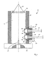
Fig. 1 zeigt eine Heizvorrichtung 10, mittels der ein in einer nur angedeuteten Düse 13 strömendes Medium erwärmt werden kann. Die Heizvorrichtung 10 umfasst eine gestellfeste Grundplatte 15, auf der ein Reflektorrohr 12 gehalten ist. Innerhalb des Reflektorrohres 12 verläuft mit radialem Abstand die Düse 13. Auf die Düse 13 ist axial ein hülsenförmiges Heizelement 11 aufgeschoben, das zwischen der Düse 13 und dem äußeren Reflektorrohr 12 angeordnet ist und über eine Drehsicherung 16, die an der Grundplatte 15 ausgebildet ist, drehsicher festgelegt ist. Des Weiteren ist das Heizelement 11 mittels einer Sicherung 14 in axialer Richtung auf der Düse 13 festgelegt.1 shows a
In der Mantelfläche des Heizelementes 11 sind zwei axial beabstandete Ausnehmungen 11a ausgebildet, in denen jeweils eine Kontaktfläche 26 eines in oder an dem Heizelement 11 angeordneten, nicht dargestellten elektrischen Leiters ausgebildet ist.In the lateral surface of the
In dem Reflektorrohr 12 ist in den Kontaktflächen 26 benachbarten bzw. gegenüberliegenden Bereichen jeweils eine Gewindebohrung 12a mit einem Innengewinde 21 ausgebildet. Eine elektrische Anschlussleitung 17 besitzt ein endseitiges Kontaktstück 18, das durch die Gewindebohrung 12a hindurchgesteckt und lose auf die Kontaktfläche 26 des Heizelementes 11 aufgelegt werden kann. Eine auf die Anschlussleitung 17 verschieblich aufgesetzte Spannschraube 22, die als Überwurfmutter ausgebildet ist, in ihrem Inneren mit einem elastischen Isolierkörper 19 gefüllt, der das Kontaktstück 18 zumindest teilweise umgibt und abschirmt. Die Spannschraube 22 besitzt ein Außengewinde, das mit dem Innengewinde 21 der Gewindebohrung 12a des Reflektorrohres 12 in Eingriff tritt. Beim Einschrauben der Spannschraube 22 in die Gewindebohrung des Reflektorrohres 12 wird die Spannschraube 22 relativ zum Heizelement 11 radial nach innen bewegt, wodurch das auf der Innenseite der Spannschraube 22 hervorstehende Kontaktstück 18 gegen die Kontaktfläche 26 des Heizelementes 11 gespannt wird. Die von der Spannschraube 22 erzeugte Spannkraft wirkt radial nach innen und damit im Wesentlichen normal zur Kontaktfläche 26 des Heizelementes 11. Infolge der Spannkraft ist somit das Kontaktstück 18 in großflächiger Anlage an der Kontaktfläche 26.In the
Um das Heizelement 11 auszuwechseln, werden die Spannschrauben 22 soweit aus der jeweiligen Gewindebohrung 12a des Reflektorrohres 12 herausgedreht, dass die Anschlussleitungen 17 mit ihrem jeweiligen Kontaktstück 18 außer Anlage mit der Kontaktfläche 26 des Heizelementes 11 kommen. Nach Lösen der axialen Sicherung 14 kann das Heizelement 11 in axialer Richtung von der Düse 13 abgenommen werden. Anschließend wird ein neues Heizelement auf die Düse aufgeschoben und durch Einschrauben der Spannschrauben 22 elektrisch angeschlossen, indem die Kontaktstücke 18 gegen die Kontaktflächen des neuen Heizelementes gespannt werden.In order to replace the
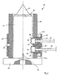
Während bei der Ausgestaltung gemäß Fig. 1 die Spannkraft, mittels der das Kontaktstück 18 gegen die Kontaktfläche 26 gespannt wird, durch eine mit dem Reflektorrohr 12 in Eingriff stehende Spannschraube 22 erzeugt wird, zeigt Fig. 2 eine alternative Ausgestaltung, bei der auf der Außenseite des Reflektorrohres 12 ein Federbügel 23 angeordnet ist, die über einen Stift 25 am Reflektorrohr 12 festgelegt ist. In einer Bohrung 12b des Reflektorrohres 12 sitzt ein becherförmiges Druckstück 24, das der vorgenannten Spannschraube mit Ausnahme des Gewindes entspricht und den Isolierkörper 19 aufnimmt, der seinerseits in genannter Weise das Kontaktstück 18 umgibt. Das Druckstück 24 sitzt radial verschieblich in der Bohrung 12b und wird mittels der Federbügels 23 mit einer radial nach innen gerichteten Spannkraft beaufschlagt, wodurch das Kontaktstück 18 gegen die Kontaktfläche 26 des Heizelementes 11 gespannt wird. Zum Auswechseln des Heizelementes 11 wird entweder der Federbügel 23 gelöst oder die Kontaktstücke 18 werden zusammen mit den Isolierkörpern 19 und den Druckstücken 24 entgegen der Federkraft des Federbügels 23 soweit radial nach außen gezogen, dass das Heizelement 11 freikommt und von der Düse 13 abgezogen werden kann.While in the embodiment of FIG. 1, the clamping force by means of the
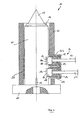
Während bei den beiden vorgenannten Ausführungsbeispielen die Kontaktfläche 26 jeweils in einer Ausnehmung 11a des Mantels des Heizelementes 11 ausgebildet ist, zeigt Fig. 3 eine Abwandlung, indem das Heizelement 11 zwei radial nach außen hervorstehende Anschlussteile 27 besitzt, die jeweils mit einem Kontaktstück 18 in Anlage gebracht werden können. Bei den Anschlussteilen 27 kann es sich um Anschlussstutzen oder Anschlussbolzen handeln. Bezüglich des weiteren Aufbaus entspricht die in Fig. 3 dargestellte Heizvorrichtung 10 der Heizvorrichtung gemäß Fig. 2.While in the two aforementioned embodiments, the
Fig. 4 zeigt eine Abwandlung der Spannvorrichtung gemäß Fig. 2. Die Spannvorrichtung gemäß Fig. 2 zeigt einen auf der Außenseite des Reflektorrohres 12 angeordneten Federbügel. Auch die Ausgestaltung gemäß Fig. 4 zeigt einen entsprechenden Federbügel, dieser umgreift jedoch direkt das Heizelement 11 und durchgreift das Reflektorrohr 12 an einer Aussparung 12b, so dass es in genannter Weise auf die radial außenliegende Fläche der Druckstücke 24 einwirken und diese radial nach innen beaufschlagen kann, wodurch die Spannkraft unter Zwischenschaltung der Isolierkörper 19 die Kontaktstücke 18 radial nach innen auf die radial äußeren Kontakflächen 26 des Heizelementes 11 spannt.FIG. 4 shows a modification of the tensioning device according to FIG. 2. The tensioning device according to FIG. 2 shows a spring clip arranged on the outside of the
Claims (13)
- Heating element for placing on a pipe or nozzle (13), with a current-carrying conductor connectable by means of connecting leads (17) to a power supply, the connecting leads (17) in each case having a terminal contact piece (18) which can be engaged with a contact surface (26) of the heating element (11), and where a clamping device (20) is provided by means of which the contact piece (18) can be clamped against the heating element (11), characterized in that the contact piece (18) rests loosely on the contact surface (26) and that the clamping force of the clamping device (20) acts in a substantially normal manner to the contact surface (26) and clamps the contact piece (18) against the contact surface (26).
- Heating element according to claim 1, characterized in that the contact surface (26) is located on the radially outer side of the heating element (11).
- Heating element according to claim 1 or 2, characterized in that the contact surface (26) is formed in a recess (11a) of a jacket of the heating element (11).
- Heating element according to claim 1 or 2, characterized in that the contact surface (26) is formed on a radially projecting connection part (27) of the heating element (11).
- Heating element according to one of the claims 1 to 4, characterized in that the contact surface (26) is smooth and that the contact piece (18) with a complimentary bearing surface engages in large-area manner on the contact surface (26).
- Heating element according to one of the claims 1 to 5, characterized in that the clamping device (20) incorporates a locking screw (22).
- Heating element according to claim 6, characterized in that the locking screw (22) is in engagement with a thread (21) of a reflector tube (12) surrounding the heating element (11).
- Heating element according to one of the claims 1 to 5, characterized in that the locking device (20) incorporates a clamp (23) at least partly embracing the heating element (11).
- Heating element according to one of the claims 1 to 8, characterized in that the contact piece (18) is surrounded by an insulator (19).
- Heating element according to claim 9, characterized in that the clamping force can be applied to the contact piece (18) via the insulator (19).
- Heating element according to claim 9 or 10, characterized in that the insulator (19) is elastic and in particular springy.
- Heating element according to one of the claims 9 to 11, characterized in that insulator (19) is formed from a foam material.
- Heating element according to one of the claims 1 to 12, characterized in that the heating element (11) can be secured in rotation-prevented manner on the pipe or nozzle (13).
Applications Claiming Priority (3)
| Application Number | Priority Date | Filing Date | Title |
|---|---|---|---|
| DE10252389 | 2002-11-12 | ||
| DE10252389A DE10252389A1 (en) | 2002-11-12 | 2002-11-12 | A method for connecting the electrical supply to the heating element of an injection nozzle has fixed terminals contacting the element to ease replacement |
| PCT/EP2003/012500 WO2004043672A1 (en) | 2002-11-12 | 2003-11-10 | Heating element arranged on a tubular conduit |
Publications (2)
| Publication Number | Publication Date |
|---|---|
| EP1560692A1 EP1560692A1 (en) | 2005-08-10 |
| EP1560692B1 true EP1560692B1 (en) | 2006-08-30 |
Family
ID=32185461
Family Applications (1)
| Application Number | Title | Priority Date | Filing Date |
|---|---|---|---|
| EP03779868A Expired - Lifetime EP1560692B1 (en) | 2002-11-12 | 2003-11-10 | Heating element arranged on a tubular conduit |
Country Status (9)
| Country | Link |
|---|---|
| US (1) | US7067774B2 (en) |
| EP (1) | EP1560692B1 (en) |
| AT (1) | ATE337901T1 (en) |
| AU (1) | AU2003288015A1 (en) |
| CA (1) | CA2505492C (en) |
| DE (2) | DE10252389A1 (en) |
| ES (1) | ES2273058T3 (en) |
| MX (1) | MXPA05004502A (en) |
| WO (1) | WO2004043672A1 (en) |
Families Citing this family (9)
| Publication number | Priority date | Publication date | Assignee | Title |
|---|---|---|---|---|
| FR2888153B1 (en) * | 2005-07-05 | 2007-09-07 | Delachaux Sa Sa | NOZZLE NOZZLE HEATING INJECTION-MOLDING DEVICE |
| US7462031B2 (en) * | 2005-11-25 | 2008-12-09 | Mold-Masters (2007) Limited | Injection molding nozzle with recessed terminal |
| ITMO20060314A1 (en) * | 2006-10-05 | 2008-04-06 | Maria Prudenziati | INNOVATIVE HEATING ELEMENT, IN PARTICULAR FOR HOT ROOMS OF PLASTIC INJECTION MOLDING EQUIPMENT |
| DE202007014964U1 (en) * | 2007-10-25 | 2009-02-26 | Günther Heisskanaltechnik Gmbh | connecting device |
| DE102008015378A1 (en) * | 2008-03-20 | 2009-09-24 | Fraunhofer-Gesellschaft zur Förderung der angewandten Forschung e.V. | Pin and electrical connection |
| DE102010049467B4 (en) | 2010-10-27 | 2022-08-04 | Günther Heisskanaltechnik Gmbh | Electrical connection device for an electrical heating element of a hot runner nozzle and hot runner nozzle |
| DE102012101400B4 (en) | 2012-02-22 | 2013-10-31 | Günther Heisskanaltechnik Gmbh | Hot runner nozzle with an electric heating element |
| CN103501553A (en) * | 2013-10-16 | 2014-01-08 | 钟梅香 | Heating element leading-out bar |
| JP2024081918A (en) * | 2022-12-07 | 2024-06-19 | 日本特殊陶業株式会社 | Liquid Heating Device |
Family Cites Families (9)
| Publication number | Priority date | Publication date | Assignee | Title |
|---|---|---|---|---|
| DE1062358B (en) * | 1953-05-05 | 1959-07-30 | Andrew George Heron | Flexible hose with which electrical conductors in the form of a hose-like metal mesh are connected for resistance heating |
| DE1841205U (en) * | 1960-05-21 | 1961-11-09 | Kurt Maurer | LIQUID PIPING. |
| USRE29332E (en) * | 1973-06-15 | 1977-08-02 | Thermon Manufacturing Company | Pipe heat transfer assembly and method of making same |
| DE2511137A1 (en) * | 1975-03-14 | 1976-09-30 | Tuerk & Hillinger Kg | Heater for round objects - consists of two metal clad sealed elements hinged to one another |
| GB1520326A (en) * | 1976-04-28 | 1978-08-09 | Hedin Ltd | Mounting electric resistance heating elements |
| DE3268829D1 (en) * | 1981-09-30 | 1986-03-13 | Fusion Plastics Ltd | Electro-fusion fitting |
| CA1268616A (en) * | 1987-10-16 | 1990-05-08 | Mold-Masters Limited | Method of manufacture of injection molding nozzle electrical terminal |
| CA2078180C (en) * | 1992-09-10 | 2000-01-18 | Craig W. Renwick | Injection molding nozzle having an electrical terminal with an insulative connector |
| DE29510136U1 (en) * | 1995-06-22 | 1995-09-07 | Hotset Heizpatronen u. Zubehör GmbH, 58511 Lüdenscheid | Pipe-like heating element for heating hot runner nozzles and the like. |
-
2002
- 2002-11-12 DE DE10252389A patent/DE10252389A1/en not_active Withdrawn
-
2003
- 2003-11-10 WO PCT/EP2003/012500 patent/WO2004043672A1/en not_active Ceased
- 2003-11-10 EP EP03779868A patent/EP1560692B1/en not_active Expired - Lifetime
- 2003-11-10 DE DE50304890T patent/DE50304890D1/en not_active Expired - Lifetime
- 2003-11-10 MX MXPA05004502A patent/MXPA05004502A/en unknown
- 2003-11-10 ES ES03779868T patent/ES2273058T3/en not_active Expired - Lifetime
- 2003-11-10 CA CA2505492A patent/CA2505492C/en not_active Expired - Fee Related
- 2003-11-10 AT AT03779868T patent/ATE337901T1/en not_active IP Right Cessation
- 2003-11-10 AU AU2003288015A patent/AU2003288015A1/en not_active Abandoned
-
2005
- 2005-05-12 US US11/127,500 patent/US7067774B2/en not_active Expired - Lifetime
Also Published As
| Publication number | Publication date |
|---|---|
| MXPA05004502A (en) | 2005-11-23 |
| ES2273058T3 (en) | 2007-05-01 |
| AU2003288015A1 (en) | 2004-06-03 |
| DE50304890D1 (en) | 2006-10-12 |
| DE10252389A1 (en) | 2004-05-27 |
| CA2505492C (en) | 2011-01-25 |
| EP1560692A1 (en) | 2005-08-10 |
| ATE337901T1 (en) | 2006-09-15 |
| CA2505492A1 (en) | 2004-05-27 |
| US20050211693A1 (en) | 2005-09-29 |
| WO2004043672A9 (en) | 2005-05-26 |
| US7067774B2 (en) | 2006-06-27 |
| WO2004043672A8 (en) | 2005-03-17 |
| WO2004043672A1 (en) | 2004-05-27 |
Similar Documents
| Publication | Publication Date | Title |
|---|---|---|
| EP1223017B1 (en) | Hot runner nozzle | |
| DE2510214C3 (en) | Lamp holder for lamps that get very hot | |
| DE3533318A1 (en) | DESOLDERING DEVICE AND USEABLE DESOLDERING TIP | |
| EP1560692B1 (en) | Heating element arranged on a tubular conduit | |
| DE2124428B2 (en) | Connector for coaxial pairs of communication cables | |
| DE3427207C2 (en) | ||
| DE69520165T2 (en) | Method of making an electrofusion socket | |
| EP1470620A1 (en) | Pole terminal | |
| DE69012223T2 (en) | Heater and heating element. | |
| CH670918A5 (en) | ||
| EP1605490B1 (en) | Vehicle lamp | |
| EP2448369B1 (en) | Electrical connection device for an electric heating element of a hot runner nozzle | |
| DE3247673C2 (en) | Socket with a field control element | |
| DE3243690C2 (en) | Contact device for a power supply system | |
| EP1657795A1 (en) | Cable plug of a plug-type connection device for medium-voltage and high-voltage technics | |
| DE835768C (en) | Plug-in coupling for electrical lines | |
| EP0073423A1 (en) | Connection element for a conductor with a solid insulation | |
| DE4331969A1 (en) | Inductive speed sensor | |
| DE2740232C3 (en) | Connecting sleeve | |
| AT3893U1 (en) | LOAD CONNECTOR | |
| DE2251446C3 (en) | Brush for electrical machines | |
| DE2253529A1 (en) | DEVICE FOR THE ELECTRICALLY INSULATED JOINT OF TWO METAL PIPES | |
| EP3128806A1 (en) | Heating element for a flow channel or a mould cavity and injection molding nozzle with such a heating element | |
| DE19506668A1 (en) | Assembly aid for installing a circuit board in a housing | |
| DE202024100841U1 (en) | Power combo connection and charging gun head |
Legal Events
| Date | Code | Title | Description |
|---|---|---|---|
| PUAI | Public reference made under article 153(3) epc to a published international application that has entered the european phase |
Free format text: ORIGINAL CODE: 0009012 |
|
| 17P | Request for examination filed |
Effective date: 20050519 |
|
| AK | Designated contracting states |
Kind code of ref document: A1 Designated state(s): AT BE BG CH CY CZ DE DK EE ES FI FR GB GR HU IE IT LI LU MC NL PT RO SE SI SK TR |
|
| AX | Request for extension of the european patent |
Extension state: AL LT LV MK |
|
| GRAP | Despatch of communication of intention to grant a patent |
Free format text: ORIGINAL CODE: EPIDOSNIGR1 |
|
| DAX | Request for extension of the european patent (deleted) | ||
| GRAS | Grant fee paid |
Free format text: ORIGINAL CODE: EPIDOSNIGR3 |
|
| GRAA | (expected) grant |
Free format text: ORIGINAL CODE: 0009210 |
|
| AK | Designated contracting states |
Kind code of ref document: B1 Designated state(s): AT BE BG CH CY CZ DE DK EE ES FI FR GB GR HU IE IT LI LU MC NL PT RO SE SI SK TR |
|
| PG25 | Lapsed in a contracting state [announced via postgrant information from national office to epo] |
Ref country code: IT Free format text: LAPSE BECAUSE OF FAILURE TO SUBMIT A TRANSLATION OF THE DESCRIPTION OR TO PAY THE FEE WITHIN THE PRESCRIBED TIME-LIMIT;WARNING: LAPSES OF ITALIAN PATENTS WITH EFFECTIVE DATE BEFORE 2007 MAY HAVE OCCURRED AT ANY TIME BEFORE 2007. THE CORRECT EFFECTIVE DATE MAY BE DIFFERENT FROM THE ONE RECORDED. Effective date: 20060830 Ref country code: SI Free format text: LAPSE BECAUSE OF FAILURE TO SUBMIT A TRANSLATION OF THE DESCRIPTION OR TO PAY THE FEE WITHIN THE PRESCRIBED TIME-LIMIT Effective date: 20060830 Ref country code: FI Free format text: LAPSE BECAUSE OF FAILURE TO SUBMIT A TRANSLATION OF THE DESCRIPTION OR TO PAY THE FEE WITHIN THE PRESCRIBED TIME-LIMIT Effective date: 20060830 Ref country code: IE Free format text: LAPSE BECAUSE OF FAILURE TO SUBMIT A TRANSLATION OF THE DESCRIPTION OR TO PAY THE FEE WITHIN THE PRESCRIBED TIME-LIMIT Effective date: 20060830 Ref country code: SK Free format text: LAPSE BECAUSE OF FAILURE TO SUBMIT A TRANSLATION OF THE DESCRIPTION OR TO PAY THE FEE WITHIN THE PRESCRIBED TIME-LIMIT Effective date: 20060830 Ref country code: RO Free format text: LAPSE BECAUSE OF FAILURE TO SUBMIT A TRANSLATION OF THE DESCRIPTION OR TO PAY THE FEE WITHIN THE PRESCRIBED TIME-LIMIT Effective date: 20060830 |
|
| REG | Reference to a national code |
Ref country code: GB Ref legal event code: FG4D Free format text: NOT ENGLISH |
|
| REG | Reference to a national code |
Ref country code: CH Ref legal event code: EP |
|
| REG | Reference to a national code |
Ref country code: IE Ref legal event code: FG4D Free format text: LANGUAGE OF EP DOCUMENT: GERMAN |
|
| REF | Corresponds to: |
Ref document number: 50304890 Country of ref document: DE Date of ref document: 20061012 Kind code of ref document: P |
|
| PG25 | Lapsed in a contracting state [announced via postgrant information from national office to epo] |
Ref country code: DK Free format text: LAPSE BECAUSE OF FAILURE TO SUBMIT A TRANSLATION OF THE DESCRIPTION OR TO PAY THE FEE WITHIN THE PRESCRIBED TIME-LIMIT Effective date: 20061130 Ref country code: BG Free format text: LAPSE BECAUSE OF FAILURE TO SUBMIT A TRANSLATION OF THE DESCRIPTION OR TO PAY THE FEE WITHIN THE PRESCRIBED TIME-LIMIT Effective date: 20061130 Ref country code: MC Free format text: LAPSE BECAUSE OF NON-PAYMENT OF DUE FEES Effective date: 20061130 Ref country code: SE Free format text: LAPSE BECAUSE OF FAILURE TO SUBMIT A TRANSLATION OF THE DESCRIPTION OR TO PAY THE FEE WITHIN THE PRESCRIBED TIME-LIMIT Effective date: 20061130 |
|
| GBT | Gb: translation of ep patent filed (gb section 77(6)(a)/1977) |
Effective date: 20061129 |
|
| REG | Reference to a national code |
Ref country code: CH Ref legal event code: NV Representative=s name: TROESCH SCHEIDEGGER WERNER AG |
|
| PG25 | Lapsed in a contracting state [announced via postgrant information from national office to epo] |
Ref country code: PT Free format text: LAPSE BECAUSE OF FAILURE TO SUBMIT A TRANSLATION OF THE DESCRIPTION OR TO PAY THE FEE WITHIN THE PRESCRIBED TIME-LIMIT Effective date: 20070206 |
|
| ET | Fr: translation filed | ||
| REG | Reference to a national code |
Ref country code: IE Ref legal event code: FD4D |
|
| REG | Reference to a national code |
Ref country code: ES Ref legal event code: FG2A Ref document number: 2273058 Country of ref document: ES Kind code of ref document: T3 |
|
| PLBE | No opposition filed within time limit |
Free format text: ORIGINAL CODE: 0009261 |
|
| STAA | Information on the status of an ep patent application or granted ep patent |
Free format text: STATUS: NO OPPOSITION FILED WITHIN TIME LIMIT |
|
| 26N | No opposition filed |
Effective date: 20070531 |
|
| PGFP | Annual fee paid to national office [announced via postgrant information from national office to epo] |
Ref country code: CZ Payment date: 20071126 Year of fee payment: 5 Ref country code: ES Payment date: 20071127 Year of fee payment: 5 Ref country code: LU Payment date: 20071126 Year of fee payment: 5 Ref country code: NL Payment date: 20071121 Year of fee payment: 5 |
|
| PGFP | Annual fee paid to national office [announced via postgrant information from national office to epo] |
Ref country code: IT Payment date: 20071127 Year of fee payment: 5 Ref country code: AT Payment date: 20071114 Year of fee payment: 5 Ref country code: CH Payment date: 20071126 Year of fee payment: 5 |
|
| PGFP | Annual fee paid to national office [announced via postgrant information from national office to epo] |
Ref country code: BE Payment date: 20071126 Year of fee payment: 5 |
|
| PG25 | Lapsed in a contracting state [announced via postgrant information from national office to epo] |
Ref country code: GR Free format text: LAPSE BECAUSE OF FAILURE TO SUBMIT A TRANSLATION OF THE DESCRIPTION OR TO PAY THE FEE WITHIN THE PRESCRIBED TIME-LIMIT Effective date: 20061201 |
|
| PGFP | Annual fee paid to national office [announced via postgrant information from national office to epo] |
Ref country code: FR Payment date: 20071129 Year of fee payment: 5 Ref country code: GB Payment date: 20071112 Year of fee payment: 5 |
|
| PG25 | Lapsed in a contracting state [announced via postgrant information from national office to epo] |
Ref country code: EE Free format text: LAPSE BECAUSE OF FAILURE TO SUBMIT A TRANSLATION OF THE DESCRIPTION OR TO PAY THE FEE WITHIN THE PRESCRIBED TIME-LIMIT Effective date: 20060830 |
|
| PG25 | Lapsed in a contracting state [announced via postgrant information from national office to epo] |
Ref country code: TR Free format text: LAPSE BECAUSE OF FAILURE TO SUBMIT A TRANSLATION OF THE DESCRIPTION OR TO PAY THE FEE WITHIN THE PRESCRIBED TIME-LIMIT Effective date: 20060830 Ref country code: HU Free format text: LAPSE BECAUSE OF FAILURE TO SUBMIT A TRANSLATION OF THE DESCRIPTION OR TO PAY THE FEE WITHIN THE PRESCRIBED TIME-LIMIT Effective date: 20070301 |
|
| PG25 | Lapsed in a contracting state [announced via postgrant information from national office to epo] |
Ref country code: CY Free format text: LAPSE BECAUSE OF FAILURE TO SUBMIT A TRANSLATION OF THE DESCRIPTION OR TO PAY THE FEE WITHIN THE PRESCRIBED TIME-LIMIT Effective date: 20060830 |
|
| BERE | Be: lapsed |
Owner name: *WATLOW G.M.B.H. Effective date: 20081130 |
|
| REG | Reference to a national code |
Ref country code: CH Ref legal event code: PL |
|
| GBPC | Gb: european patent ceased through non-payment of renewal fee |
Effective date: 20081110 |
|
| PG25 | Lapsed in a contracting state [announced via postgrant information from national office to epo] |
Ref country code: NL Free format text: LAPSE BECAUSE OF NON-PAYMENT OF DUE FEES Effective date: 20090601 |
|
| NLV4 | Nl: lapsed or anulled due to non-payment of the annual fee |
Effective date: 20090601 |
|
| PG25 | Lapsed in a contracting state [announced via postgrant information from national office to epo] |
Ref country code: CZ Free format text: LAPSE BECAUSE OF NON-PAYMENT OF DUE FEES Effective date: 20081110 Ref country code: AT Free format text: LAPSE BECAUSE OF NON-PAYMENT OF DUE FEES Effective date: 20081110 Ref country code: IT Free format text: LAPSE BECAUSE OF NON-PAYMENT OF DUE FEES Effective date: 20081110 |
|
| REG | Reference to a national code |
Ref country code: FR Ref legal event code: ST Effective date: 20090731 |
|
| PG25 | Lapsed in a contracting state [announced via postgrant information from national office to epo] |
Ref country code: BE Free format text: LAPSE BECAUSE OF NON-PAYMENT OF DUE FEES Effective date: 20081130 |
|
| PG25 | Lapsed in a contracting state [announced via postgrant information from national office to epo] |
Ref country code: LI Free format text: LAPSE BECAUSE OF NON-PAYMENT OF DUE FEES Effective date: 20081130 Ref country code: CH Free format text: LAPSE BECAUSE OF NON-PAYMENT OF DUE FEES Effective date: 20081130 |
|
| PG25 | Lapsed in a contracting state [announced via postgrant information from national office to epo] |
Ref country code: GB Free format text: LAPSE BECAUSE OF NON-PAYMENT OF DUE FEES Effective date: 20081110 |
|
| REG | Reference to a national code |
Ref country code: ES Ref legal event code: FD2A Effective date: 20081111 |
|
| PG25 | Lapsed in a contracting state [announced via postgrant information from national office to epo] |
Ref country code: ES Free format text: LAPSE BECAUSE OF NON-PAYMENT OF DUE FEES Effective date: 20081111 |
|
| PG25 | Lapsed in a contracting state [announced via postgrant information from national office to epo] |
Ref country code: LU Free format text: LAPSE BECAUSE OF NON-PAYMENT OF DUE FEES Effective date: 20081110 |
|
| PG25 | Lapsed in a contracting state [announced via postgrant information from national office to epo] |
Ref country code: FR Free format text: LAPSE BECAUSE OF NON-PAYMENT OF DUE FEES Effective date: 20081130 |
|
| PGFP | Annual fee paid to national office [announced via postgrant information from national office to epo] |
Ref country code: DE Payment date: 20121121 Year of fee payment: 10 |
|
| REG | Reference to a national code |
Ref country code: DE Ref legal event code: R119 Ref document number: 50304890 Country of ref document: DE Effective date: 20140603 |
|
| PG25 | Lapsed in a contracting state [announced via postgrant information from national office to epo] |
Ref country code: DE Free format text: LAPSE BECAUSE OF NON-PAYMENT OF DUE FEES Effective date: 20140603 |