EP1560507B1 - Bag - Google Patents
Bag Download PDFInfo
- Publication number
- EP1560507B1 EP1560507B1 EP03773700A EP03773700A EP1560507B1 EP 1560507 B1 EP1560507 B1 EP 1560507B1 EP 03773700 A EP03773700 A EP 03773700A EP 03773700 A EP03773700 A EP 03773700A EP 1560507 B1 EP1560507 B1 EP 1560507B1
- Authority
- EP
- European Patent Office
- Prior art keywords
- bag
- holding element
- bag according
- central holding
- flat projection
- Prior art date
- Legal status (The legal status is an assumption and is not a legal conclusion. Google has not performed a legal analysis and makes no representation as to the accuracy of the status listed.)
- Expired - Lifetime
Links
- 239000004033 plastic Substances 0.000 claims description 13
- 229920003023 plastic Polymers 0.000 claims description 13
- 239000004753 textile Substances 0.000 claims description 9
- 230000002441 reversible effect Effects 0.000 claims 2
- 229920002994 synthetic fiber Polymers 0.000 claims 2
- 238000010422 painting Methods 0.000 abstract description 4
- 239000000463 material Substances 0.000 description 15
- 238000011161 development Methods 0.000 description 6
- 230000018109 developmental process Effects 0.000 description 6
- 239000005871 repellent Substances 0.000 description 3
- 238000010276 construction Methods 0.000 description 2
- 230000007613 environmental effect Effects 0.000 description 2
- 238000004519 manufacturing process Methods 0.000 description 2
- XLYOFNOQVPJJNP-UHFFFAOYSA-N water Substances O XLYOFNOQVPJJNP-UHFFFAOYSA-N 0.000 description 2
- 239000004677 Nylon Substances 0.000 description 1
- 230000002745 absorbent Effects 0.000 description 1
- 239000002250 absorbent Substances 0.000 description 1
- 238000004040 coloring Methods 0.000 description 1
- 239000002537 cosmetic Substances 0.000 description 1
- 238000001035 drying Methods 0.000 description 1
- 230000000694 effects Effects 0.000 description 1
- 239000004744 fabric Substances 0.000 description 1
- 239000000835 fiber Substances 0.000 description 1
- 229920002457 flexible plastic Polymers 0.000 description 1
- 238000005259 measurement Methods 0.000 description 1
- 229920001778 nylon Polymers 0.000 description 1
- 230000003014 reinforcing effect Effects 0.000 description 1
- 230000002940 repellent Effects 0.000 description 1
- 238000007789 sealing Methods 0.000 description 1
- 238000005406 washing Methods 0.000 description 1
Images


Classifications
-
- A—HUMAN NECESSITIES
- A45—HAND OR TRAVELLING ARTICLES
- A45C—PURSES; LUGGAGE; HAND CARRIED BAGS
- A45C7/00—Collapsible or extensible purses, luggage, bags or the like
- A45C7/0018—Rigid or semi-rigid luggage
- A45C7/0054—Rigid or semi-rigid luggage comprising a plurality of hinged panels to be unfolded in one plane for access purposes
-
- A—HUMAN NECESSITIES
- A45—HAND OR TRAVELLING ARTICLES
- A45C—PURSES; LUGGAGE; HAND CARRIED BAGS
- A45C11/00—Receptacles for purposes not provided for in groups A45C1/00-A45C9/00
- A45C11/38—Camera cases, e.g. of ever-ready type
Definitions
- the present invention relates to a bag according to the preamble of claim 1.
- Such utensil bags are known per se. They are used to store numerous accessories, for example, for painting or photographing, clear, gentle and captive, so that it is not damaged during transport and removed without a long search of the bag and can be covered again after use. These bags should also be neither too big nor too heavy, so that they can be transported comfortably even with content.
- the known utensil bags are characterized by the fact that a certain number of compartments for receiving accessories or other parts is fixed. Therefore, these pockets lack some flexibility, i. they can not be adapted in their design to the respective needs of the user in individual cases.
- the US patent application US 2002/0029946 A1 discloses a cosmetic and travel bag for accommodating garments with multiple wearing options.
- This bag consists of a connecting web, on each of which a pocket element is articulated on both sides.
- Each pocket element can be folded inwards once to shorten the height of the bag.
- Arrangements for accommodating objects, in particular items of clothing, are provided in the individual pocket elements.
- the object of the present invention is therefore to provide a bag and a bag sleeve of the above type, which does not have this disadvantage and can be adapted in their design to the particular needs of the user.
- the solution consists in a bag with the features of claim 1.
- the bag according to the invention is modular in its interior, therefore, to customize and versatile. It is lightweight, durable and handy and reliably protects the contents from external influences.
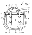
- FIG. 1 An embodiment of a bag according to the invention is shown schematically in FIG. 1 shown.
- it is a painter's bag, which is provided for receiving various painting utensils. Any other applications, such as.
- a photo bag, tool bag, sample case, etc. are of course also conceivable.
- the bag 1 is rectangular with a bottom 2, two large side walls 3,4, two small side walls 5, 6 and a lid 7.
- the lid has one or more closures 8, preferably snap closures or clip closures.
- eyelets 9 for attaching a support belt 10, for example. By means of snap hook, provided.
- An annular strap 11 runs parallel guided around the bag 1 and ends at the top in two handles 12,13.
- On each large side wall 3, 4 four lugs 14 are provided which hold the tether 11 in position and ensure the parallel guidance.
- the eyelets are also used to hang the strap 10 and a belt identical thereto (not shown) so that the bag can be worn on the back in the manner of a backpack or Ranzens.
- FIG. 2 In the unfolded state it can be seen that the bag 1 consists of several elements.
- the centerpiece is a pocket envelope 20, which in turn is composed of several components.
- One of these components is a central holding element 21, which is designed in the form of an open-topped container.
- the central holding element 21 has substantially the shape of a thin cuboid and is used to hold coloring paper, drawing block o. The like ..
- two flat parts are mounted so that they are around the are pivotable from the longitudinal edges defined axes.
- These parts are two-dimensional unwinds 24, 31 of three-dimensional, in the embodiment cuboid containers, each with a bottom 25, 32, two large side panels 26, 33, 27, 34, two small side panels 28, 35, 29, 36 and a Cover part 30, 37.
- On the surfaces of these developments 24, 31 are various containers 38, 39, 40, 42, 42, 43 reversibly attached.
- FIG. 2 is also apparent that for closing the bag 1, first the side parts 27, 34 are brought parallel to the central support member 21, that are brought into contact with the corresponding side surfaces of the central support member 21, then the large side parts 26, 33 are folded upwards small side parts 28, 29, 35, 36 are struck inwards and finally the lid parts 30, 37 is folded over so that it covers the opening of the central holding element 21. It follows that the small side walls 5 and 6 of the pocket 1 in FIG. 1 from the folded side parts 29, 36 and 28, 35 in FIG. 2 , be formed. Likewise, the large side walls 3, 4 of the bag 1 in FIG. 1 from the large side parts 26, 33 in FIG. 2 educated. The lid 7 in FIG. 1 corresponds to the lid 30, 37 in FIG. 2 ,
- any containers can be attached to the unwinds 24, 31, so that the bag 1 highly flexible can be adapted to the needs of the user.
- the pocket 1 or the compartments or containers contained in it are thus of modular construction, so that the individual containers can be put together individually according to the needs of the user.
- the tether 11 may consist of two tethers 11 a and 11 b, whose free ends are fixed to the lower longitudinal edges 22 ', 23' of the central support member 21.
- the straps 11a, 12a thus extend in a U-shape through the eyelets 14 and above the cover 7 or 30, 37, the handles 12, 13. Since the straps 11a, 11b can run freely through the eyelets 14, this means that in unfolded state of the bag 1, the tethers 11 a, 11 b only on the handles 12, 13 must be taken to fold the open pocket 1 in the manner of a Leporellos together, the unwinds 24, 31, act as folding elements, in which the large Fold side parts 26, 33, 27, 34 together like a fan. Subsequently, only the small side parts 28, 35 and 29, 36 are beaten into each other and the cover parts 30, 37 are beaten on the central support member 21 to close the bag 1. Finally, the shutters 8 are locked.
- the bag 1 is preferably a flexible plastic material, for example.
- the pocket envelope 20 is preferably made, but also the containers 38 to 43 may be made therefrom.
- the unwinds 24, 31 namely in the folded state completely enclose the central holding element 21 and the individual containers 38 to 43 and thus have a sealing effect against external influences of all kinds, in particular against the weather (rain, etc.).
- plastic-coated textile material also has the advantage that the individual parts of the pocket 1 can be sewn, which simplifies the production of the pocket 1.
- the bag 1 is relatively stable when unfolded. This can be achieved by using the flexible material in two layers and by interposing between these layers an amplifier layer, for example of a stiffer plastic material. By this stiffening the bag 1 also keeps its shape in the unfolded state and provides sufficient support to securely fix the containers 38 to 43.
- the reinforcing layer is placed between two suitably cut plastic or textile webs, and the plastic or textile layers are welded or preferably sewn at their outer edges.
- FIG. 3 shows the development 24 in a plan view FIG. 2 with the bottom 25, the large side parts 26, 27, the small side parts 28, 29 and the cover part 30.
- the free edge 26 'of the side part 26 is fixedly connected to the outer upper edge 23 of the central holding element 21.
- the dimensions of the large side parts 26, 27 correspond to those of the central holding element 21.
- the dimensions of the small side parts 28, 29 and the cover part 30 are dimensioned so that they in the folded state of the bag 1, the narrow sides of all containers 38 to 43 and the central support member Cover 21 and form a closed narrow side 5,6, as shown in Figure 1.
- strip-shaped hook and loop fasteners 44 are attached, which serve to attach containers 38 to 43.
- strip-shaped hook and loop fasteners 45 are attached along the free edges of the side parts 28, 29 and the cover part 30, which serve to close the bag 1.
- FIG. 4 Comparably shows FIG. 4 the settlement 31 from FIG. 2 with the bottom 32, the large side parts 33, 34, the small side parts 35, 36 and the cover part 37.
- the free edge 34 'of the side part 34 is fixedly connected to the outer upper edge 22 of the central holding element 21.
- the dimensions of the large side parts 33, 34 correspond to those of the central holding element 21.
- the dimensions of the small side parts 35, 36 and the cover part 37 are dimensioned so that they in the folded state of the bag 1, the narrow sides of all containers 38 to 43 and the central support member Cover 21 and form a closed narrow side 5,6, as shown in Figure 1.
- strip-shaped hook-and-loop fasteners 46 are attached, which serve for the attachment of containers 38 to 43.
- the lid part 37 is folded over the upper narrow sides of the central holding element 21 and the containers now formed by the unwinds 24, 31 and the lid part 30 is beaten over until the respective hook and loop fasteners 47, 45 come into contact.
- the lid 7 in FIG. 1 educated. Since both the side parts 5, 6 and the lid 7 of the bag 1 are formed by double-layered side parts of the unwinds 24, 31, the bag 1 and its contents are particularly well protected from environmental influences.
- FIG. 5 shows a container 39, which itself is again designed as a development, with a bottom 50, two large side parts 51, 52, two small side parts 53, 54 and a cover part 55.
- the dimensions of the large side parts 26, 27 corresponds to those of the central holding element 21st
- the large side panel is used, for example, to accommodate small parts such as brushes or pencils, for example, in the manner of a writing or pencil case loops for receiving the parts can be attached.
- strip-shaped hook and loop fasteners 56, 57 are mounted, which serve to seal the container 39.
- the small side parts 53, 54 are folded inwards. Then the large side part 52 is struck so that the hook and loop fasteners 56, 57 come into contact and connect the parts together. Finally, the cover part 55 is struck over the side part 52 until the corresponding hook and loop fasteners 56, 57 come into contact, so that the container 39 is completely closed. Furthermore, strip-shaped hook and loop fasteners 58 are attached to the outside of the side part 51, with which the container 39, for example. On the inside of a large side part 33, 34, 26, 27 a settlement 24, 31 can be attached.
- the container 39 may, for example, with an absorbent material, eg terry, be designed to receive wet brush. Since it can be spread as a two-dimensional development, it can also be designed for drying.
- FIGS. 6a to 6d show further containers 38, 40, 41, 42, which are provided on their outer sides with hook and loop fasteners 59, with which they can on the inner surface of one of the large side parts 26, 27, 33, 34 a settlement 24, 31 are attached.
- the containers can be open or completely closed on the sides, for example with a zipper.
- painting utensils such as paper, water (eg. In dense plastic containers), vessels for washing brushes, sponges u.
- the folded bag 1 with the folded-up transactions 24, 31 provides a secure seal.
- the arrangement of the hook and loop fasteners can be chosen freely, depending on the application of the bag 1 and depending on the type of containers used 38 to 43. It is also advantageous if the thickness of the containers 38 to 43 and the corresponding Dimensions of the unwinds 24, 31 are always identical or as a multiple of a common unit of measurement, for example. 2 cm are selected. In this way, all the containers 38 to 43 fit all the Velcro closures and in each area of the unwinds 24, 31, so that their positioning within the pocket 1 is completely arbitrary.
- the containers 38 to 43 are preferably made of the same material as the pocket envelope 20, that is to say of a flexible material, preferably of a plastic or textile material or plastic-coated textile material. Again, the material can be used in two layers, with an intermediate amplifier layer, for example. From a stiffer plastic material. Through this stiffening preserve the containers, even if they are empty, their shape and provide enough support to one hand, the respective utensils safely and on the other hand to be securely attached to the bag cover 20 on the other hand.
- FIG. 7 finally shows an accessory bag 60, eg. For a collapsible stool.
- the accessory bag has loops 61, 62.
- the accessory bag can be attached to the loops 61, 62 fasteners, such as snap hooks on the eyelets 9 on an outside of the bag 1 are attached (not shown).
- fasteners such as snap hooks on the eyelets 9 on an outside of the bag 1 are attached (not shown).
- the bag 1 can also be worn in the manner of a backpack by the shoulder strap 10 and a second strap are hung in the eyelets on the second outer side of the bag 1 (see above).
- the bag 1 according to the invention is therefore modular in its interior, therefore to design individually and versatile. It is lightweight, durable and handy and reliably protects the contents from external influences.
Abstract
Description
Die vorliegende Erfindung betrifft eine Tasche nach dem Oberbegriff des Anspruch 1.The present invention relates to a bag according to the preamble of
Derartige Utensilientaschen sind an sich bekannt. Sie dienen dazu, zahlreiches Zubehör, bspw. zum Malen oder Fotografieren, übersichtlich, schonend und verliersicher zu verstauen, so dass es beim Transport nicht beschädigt wird und ohne längeres Suchen der Tasche entnommen und nach Gebrauch wieder zurückgelegt werden kann. Diese Taschen sollen außerdem weder zu groß noch zu schwer sein, so dass sie auch mit Inhalt noch komfortabel transportiert werden können.Such utensil bags are known per se. They are used to store numerous accessories, for example, for painting or photographing, clear, gentle and captive, so that it is not damaged during transport and removed without a long search of the bag and can be covered again after use. These bags should also be neither too big nor too heavy, so that they can be transported comfortably even with content.
Die bekannten Utensilientaschen zeichnen sich dadurch aus, dass eine bestimmte Anzahl Fächer zur Aufnahme von Zubehör- oder sonstigen Teilen fest vorgegeben ist. Daher lassen diese Taschen eine gewisse Flexibilität vermissen, d.h. sie können in ihrer Auslegung nicht an die jeweiligen Bedürfnisse des Benutzers im Einzelfall angepasst werden.The known utensil bags are characterized by the fact that a certain number of compartments for receiving accessories or other parts is fixed. Therefore, these pockets lack some flexibility, i. they can not be adapted in their design to the respective needs of the user in individual cases.
Die U.S.-amerikanische Patentanmeldung
Die Aufgabe der vorliegenden Erfindung ist es daher, eine Tasche und eine Taschenhülle der o.g. Art bereit zu stellen, die diesen Nachteil nicht aufweist und in ihrer Auslegung an die jeweiligen Bedürfnisse des Benutzers angepasst werden kann.The object of the present invention is therefore to provide a bag and a bag sleeve of the above type, which does not have this disadvantage and can be adapted in their design to the particular needs of the user.
Die Lösung besteht in einer Tasche mit den Merkmalen des Anspruchs 1. Die erfindungsgemäße Tasche ist in ihrem Inneren modular aufgebaut, daher individuell zu gestalten und vielseitig verwendbar. Sie ist leicht, strapazierfähig und handlich und schützt den Inhalt zuverlässig vor äußeren Einflüssen.The solution consists in a bag with the features of
Vorteilhafte Weiterbildungen ergeben sich aus den Unteransprüchen.Advantageous developments emerge from the subclaims.
Ein Ausführungsbeispiel der vorliegenden Erfindung wird im Folgenden anhand der beigefügten schematischen und nicht maßstabsgetreuen Zeichnungen näher erläutert. Es zeigen:
Figur 1- ein Ausführungsbeispiel der erfindungsgemäßen Tasche in perspektivischer Seitenansicht;
Figur 2- eine perspektivische Darstellung der geöffneten Tasche aus
Figur 1 Figur 3- die Draufsicht auf ein erstes seitliches Taschenelement der Tasche aus
Figur 1 Figur 4- die Draufsicht auf ein zweites seitliches Taschenelement der Tasche aus
Figur 1 Figur 5- die Draufsicht auf ein geöffnetes Behältnis für die Tasche aus
Figur 1 - Figuren 6a bis 6d
- perspektivische Darstellungen weiterer Behältnisse für die Tasche aus
Figur 1 - Figur 7
- ein Ausführungsbeispiel einer Zubehörtasche für die Tasche aus
Figur 1
- FIG. 1
- an embodiment of the bag according to the invention in a perspective side view;
- FIG. 2
- a perspective view of the opened bag
FIG. 1 ; - FIG. 3
- the top view of a first side pocket element of the bag
FIG. 1 ; - FIG. 4
- the top view of a second side pocket element of the bag
FIG. 1 ; - FIG. 5
- the top view of an opened container for the bag
FIG. 1 ; - FIGS. 6a to 6d
- perspective views of other containers for the bag
FIG. 1 ; - FIG. 7
- an embodiment of an accessory bag for the bag
FIG. 1 ,
Ein Ausführungsbeispiel einer erfindungsgemäßen Tasche ist schematisch in
Die Tasche 1 ist rechteckig mit einem Boden 2, zwei großen Seitenwänden 3,4, zwei kleinen Seitenwänden 5, 6 und einem Deckel 7. Der Deckel weist ein oder mehrere Verschlüsse 8, vorzugsweise Schnappverschlüsse oder Clipverschlüsse auf. Ferner sind an den kleinen Seitenwänden 5, 6 Ösen 9 zum Einhängen eines Tragriemens 10, bspw. mittels Karabinerhaken, vorgesehen. Ein ringförmiger Halteriemen 11 läuft parallel geführt rund um die Tasche 1 und endet an der Oberseite in zwei Henkeln 12,13. Auf jeder großen Seitenwand 3, 4 sind vier Ösen 14 vorgesehen, die den Halteriemen 11 in Position halten und die parallele Führung gewährleisten. Die Ösen dienen auch dazu, den Tragriemen 10 sowie einen damit identischen Riemen (nicht dargestellt) derart einzuhängen, dass die Tasche nach Art eines Rucksackes oder Ranzens auf dem Rücken getragen werden kann.The
Der Aufbau der Tasche 1 ergibt sich aus
Aus
Da die verschiedenen Behältnisse 38 bis 43 in
Nicht dargestellt ist, dass der Halteriemen 11 aus zwei Halteriemen 11a und 11b bestehen kann, deren freie Enden an den unteren Längskanten 22', 23' des zentralen Halteelements 21 befestigt sind. Die Halteriemen 11a, 12a verlaufen somit U-förmig durch die Ösen 14 und bilden oberhalb des Deckels 7 bzw. 30, 37 die Henkel 12, 13. Da die Halteriemen 11a, 11b frei durch die Ösen 14 laufen können, bedeutet dies, dass in aufgeklapptem Zustand der Tasche 1 die Halteriemen 11 a, 11b lediglich an den Henkeln 12, 13 ergriffen werden müssen, um die geöffnete Tasche 1 nach Art eines Leporellos zusammen zu klappen, wobei die Abwicklungen 24, 31, als Klappelemente wirken, bei denen die großen Seitenteile 26, 33, 27, 34 leporelloartig zusammenklappen. Anschließend müssen lediglich die kleinen Seitenteile 28, 35 bzw. 29, 36 ineinander geschlagen und die Deckelteile 30, 37 über das zentrale Halteelement 21 geschlagen werden, um die Tasche 1 zu schließen. Zum Schluss werden die Verschlüsse 8 eingerastet.Not shown is that the
Als Material für die Tasche 1 kommt vorzugsweise ein flexibles Kunststoffmaterial, bspw. ein wasserabweisender Kunststoff oder ein kunststoffbeschichtetes bzw. vorzugsweise aus Kunststofffasern hergestelltes Textilmaterial, bspw. Nylongewebe, zum Einsatz. Aus diesem Material ist vorzugsweise die Taschenhülle 20 hergestellt, aber auch die Behältnisse 38 bis 43 können daraus hergestellt sein. Dies hat den Vorteil, dass die Tasche 1 wasser- und schmutzabweisend sowie abwaschbar und dank der besonderen Konstruktion aus zentralem Halteelement 21 und zusammenfaltbaren Abwicklungen 24, 31, auch wasserdicht ist. Die Abwicklungen 24, 31 umschließen nämlich in zusammengefaltetem Zustand vollständig das zentrale Halteelement 21 und die einzelnen Behältnisse 38 bis 43 und wirken somit abdichtend gegen äußere Einflüsse aller Art, insbesondere gegen die Witterung (Regen etc.). Dies ist besonders bei der Verwendung als Malertasche von Vorteil, da sowohl die verwendeten Papiere als auch die fertigen Bilder sicher vor Feuchtigkeit geschützt sind. Zur weiteren Absicherung vor Feuchtigkeit und sonstigen Umwelteinflüssen können die Innenflächen des verwendeten Kunststoff- oder Textilmaterials zusätzlich gummiert oder auf andere Weise wasserabweisend beschichtet sein. Kunststoffbeschichtetes Textilmaterial hat ferner den Vorteil, dass die einzelnen Teile der Tasche 1 genäht werden können, was die Herstellung der Tasche 1 vereinfacht.As a material for the
Aus
In vergleichbarer Weise zeigt
Aus der Zusammenschau der
Die Natur der Behältnisse 38 bis 43 ergibt sich aus den
Die
Es versteht sich von selbst, dass die Anordnung der Klettverschlüsse frei gewählt werden kann, je nach Anwendungsgebiet der Tasche 1 und je nach Art der verwendeten Behältnisse 38 bis 43. Es ist ferner von Vorteil, wenn die Dicke der Behältnisse 38 bis 43 und die entsprechenden Abmessungen der Abwicklungen 24, 31 immer identisch bzw. als Vielfache einer gemeinsamen Maßeinheit, bspw. 2 cm gewählt werden. Auf diese Weise passen alle Behältnisse 38 bis 43 zu allen Klettverschlüssen und in jeden Bereich der Abwicklungen 24, 31, so dass ihre Positionierung innerhalb der Tasche 1 völlig frei wählbar ist.It goes without saying that the arrangement of the hook and loop fasteners can be chosen freely, depending on the application of the
Die Behältnisse 38 bis 43 sind vorzugsweise aus demselben Material wie die Taschenhülle 20, also aus einem flexiblen Material vorzugsweise aus einem Kunststoff- oder Textilmaterial bzw. kunststoffbeschichteten Textilmaterial. Auch hier kann das Material doppelschichtig verwendet werden, mit einer dazwischen liegenden Verstärkerschicht, bspw. aus einem steiferen Kunststoffmaterial. Durch diese Versteifung bewahren die Behältnisse, auch wenn sie leer sind, ihre Form und bieten genügend Halt, um einerseits die jeweiligen Utensilien sicher aufzunehmen und um andererseits sicher an der Taschenhülle 20 befestigt zu werden.The
Die erfindungsgemäße Tasche 1 ist also in ihrem Inneren modular aufgebaut, daher individuell zu gestalten und vielseitig verwendbar. Sie ist leicht, strapazierfähig und handlich und schützt den Inhalt zuverlässig vor äußeren Einflüssen.The
Claims (9)
- Bag (1) for the reception of objects, consisting of a bag casing (20) with a central holding element (21), equipped with hinged parts, wherein the central holding element (21) has upper outer longitudinal edges (22, 23), characterized in that at least one plane casing in the form of a 2-dimensional flat projection (24,31) of a 3-dimensional receptacle is pivoted to the upper outer longitudinal edges (22, 23) and that two straps (11a, 11b) are provided which are fastened to the lower longitudinal edges (22', 23') of the central holding element (21).
- Bag according to claim 1, characterized in that the holding element (21) is shaped as a receptacle which is open at the top.
- Bag according to claim 1, characterized in that the at least one flat projection (24, 31) is pivoted to the upper outer edge (22, 23) of the central holding element (21).
- Bag according to claim 3, characterized in that the straps (11a, 11b) run free through grommets (9) which are fastened to the big side panels of the bag (1).
- Bag according to claim 4, characterized in that the straps (11a, 11b) form handles (12, 13).
- Bag according to claim 5, characterized in that the at least one flat projection (24, 31) is pivoted to the central holding element (21) in such a manner that it works as a folding element, which folds up leporello-like upon the grasping of the handles (12, 13) of the open bag (1).
- Bag according to one of the preceding claims, characterized in that the at least one flat projection (24, 31) can be folded up reversibly to a receptacle.
- Bag according to one of the preceding claims, characterized in that at least one receptacle (38-43) is reversibly fastened to the flat projection (24, 31) and/or to the central holding element (21) and that for the reversible fastening of the receptacles (38-43) and/or for the reversible folding-up of the at least one flat projection (24, 31) hook-and-loop-fasteners are provided.
- Bag according to one of the preceding claims, characterized in that it consists of synthetic material and/or textiles and/or plastic-coated textiles.
Applications Claiming Priority (3)
| Application Number | Priority Date | Filing Date | Title |
|---|---|---|---|
| DE10251517 | 2002-11-04 | ||
| DE10251517A DE10251517A1 (en) | 2002-11-05 | 2002-11-05 | Folding case for transport of photographs, paintings and important documents has set of inner containers accommodated in outer casing which has loops for carrying straps |
| PCT/EP2003/012262 WO2004041654A2 (en) | 2002-11-04 | 2003-11-04 | Bag |
Publications (2)
| Publication Number | Publication Date |
|---|---|
| EP1560507A2 EP1560507A2 (en) | 2005-08-10 |
| EP1560507B1 true EP1560507B1 (en) | 2010-04-28 |
Family
ID=32115254
Family Applications (1)
| Application Number | Title | Priority Date | Filing Date |
|---|---|---|---|
| EP03773700A Expired - Lifetime EP1560507B1 (en) | 2002-11-05 | 2003-11-04 | Bag |
Country Status (5)
| Country | Link |
|---|---|
| EP (1) | EP1560507B1 (en) |
| AT (1) | ATE465653T1 (en) |
| AU (1) | AU2003282084A1 (en) |
| DE (2) | DE10251517A1 (en) |
| WO (1) | WO2004041654A2 (en) |
Families Citing this family (1)
| Publication number | Priority date | Publication date | Assignee | Title |
|---|---|---|---|---|
| USD873558S1 (en) | 2018-01-15 | 2020-01-28 | Tom Alexander Jamieson | Folding backpack |
Family Cites Families (6)
| Publication number | Priority date | Publication date | Assignee | Title |
|---|---|---|---|---|
| DE827997C (en) * | 1948-10-02 | 1952-03-27 | Heinrich Homann | Ever-ready case, especially for doctors |
| DE1240728B (en) * | 1961-10-04 | 1967-05-18 | Fromm K G Bettwarenfabrik Dr | Sample box |
| US4489815A (en) * | 1983-06-09 | 1984-12-25 | Martinez Isidro A | Picnic bag and mat |
| DE29605619U1 (en) * | 1996-03-26 | 1996-06-05 | Dlw Ag | Sample suitcase |
| US5904230A (en) * | 1998-03-26 | 1999-05-18 | Sportsstuff Inc. | Foldable container |
| US6296094B1 (en) * | 1999-03-11 | 2001-10-02 | Wendy S. Knecht | Combination cosmetic bag and travel bag with multiple carrying modes |
-
2002
- 2002-11-05 DE DE10251517A patent/DE10251517A1/en not_active Ceased
-
2003
- 2003-11-04 DE DE50312670T patent/DE50312670D1/en not_active Expired - Lifetime
- 2003-11-04 AU AU2003282084A patent/AU2003282084A1/en not_active Abandoned
- 2003-11-04 AT AT03773700T patent/ATE465653T1/en active
- 2003-11-04 WO PCT/EP2003/012262 patent/WO2004041654A2/en not_active Application Discontinuation
- 2003-11-04 EP EP03773700A patent/EP1560507B1/en not_active Expired - Lifetime
Also Published As
| Publication number | Publication date |
|---|---|
| ATE465653T1 (en) | 2010-05-15 |
| DE10251517A1 (en) | 2004-05-19 |
| AU2003282084A8 (en) | 2004-06-07 |
| EP1560507A2 (en) | 2005-08-10 |
| WO2004041654A2 (en) | 2004-05-21 |
| AU2003282084A1 (en) | 2004-06-07 |
| WO2004041654A3 (en) | 2005-01-06 |
| DE50312670D1 (en) | 2010-06-10 |
Similar Documents
| Publication | Publication Date | Title |
|---|---|---|
| DE60116196T2 (en) | Flexible self-standing bag | |
| DE3323763A1 (en) | Carrying device for transporting articles | |
| EP1560507B1 (en) | Bag | |
| DE29917496U1 (en) | Device for storing and transporting piece goods | |
| DE4339932C2 (en) | Carrier bag | |
| DE19821047A1 (en) | Blanket, towel etc. foldable into a cushion | |
| DE202005005748U1 (en) | Utensil bag has central container with additional wall parts connected to lid, front and/or side walls through intermediate walls to form extra storage space | |
| DE102018123698B4 (en) | Transport container | |
| AT12400U1 (en) | satchel | |
| DE10213303B4 (en) | Suitcases, in particular pilot cases | |
| AT4066U1 (en) | LAUNDRY TANK | |
| DE3310579A1 (en) | FOLDABLE COVER FOR CLOTHING OD. DGL. | |
| AT8728U1 (en) | PORTABLE LUGGAGE | |
| DE202021000784U1 (en) | Travel bag | |
| DE8322914U1 (en) | HAND LUGGAGE EXTENSION ADDITION | |
| DE696432C (en) | he or the like | |
| DE3043762A1 (en) | Double-compartment holdall or saddle-bag - has flat connecting strip with grip holes linking two sections of bag | |
| AT525033A1 (en) | carrying device | |
| DE202004006919U1 (en) | Cover for a box | |
| DE202004009452U1 (en) | Folding box for transporting household articles, toys or laundry has peripheral frame and is spread by two rectangular braces whose free ends fit against junction of box walls and its floor | |
| DE202005015236U1 (en) | Foldable changing mat for babies has winding support made from flexible material, and pocket attached to winding support | |
| WO2011141560A1 (en) | Bag | |
| CH699895A2 (en) | Bag e.g. shoulder bag, for transporting e.g. file, to office, has complementary hook-and loop fastener provided in mutual reaction with another hook-and loop fastener by closing strap to fix bag in folded form | |
| DE7735352U1 (en) | Packaging for a piece of clothing | |
| DE6900605U (en) | PAPER CARRYING BAG FOR TEXTILES AND RECORDS |
Legal Events
| Date | Code | Title | Description |
|---|---|---|---|
| PUAI | Public reference made under article 153(3) epc to a published international application that has entered the european phase |
Free format text: ORIGINAL CODE: 0009012 |
|
| 17P | Request for examination filed |
Effective date: 20050506 |
|
| AK | Designated contracting states |
Kind code of ref document: A2 Designated state(s): AT BE BG CH CY CZ DE DK EE ES FI FR GB GR HU IE IT LI LU MC NL PT RO SE SI SK TR |
|
| AX | Request for extension of the european patent |
Extension state: AL LT LV MK |
|
| DAX | Request for extension of the european patent (deleted) | ||
| 17Q | First examination report despatched |
Effective date: 20060814 |
|
| GRAP | Despatch of communication of intention to grant a patent |
Free format text: ORIGINAL CODE: EPIDOSNIGR1 |
|
| GRAS | Grant fee paid |
Free format text: ORIGINAL CODE: EPIDOSNIGR3 |
|
| GRAA | (expected) grant |
Free format text: ORIGINAL CODE: 0009210 |
|
| AK | Designated contracting states |
Kind code of ref document: B1 Designated state(s): AT BE BG CH CY CZ DE DK EE ES FI FR GB GR HU IE IT LI LU MC NL PT RO SE SI SK TR |
|
| REG | Reference to a national code |
Ref country code: GB Ref legal event code: FG4D Free format text: NOT ENGLISH |
|
| REG | Reference to a national code |
Ref country code: CH Ref legal event code: EP |
|
| REG | Reference to a national code |
Ref country code: IE Ref legal event code: FG4D Free format text: LANGUAGE OF EP DOCUMENT: GERMAN |
|
| REF | Corresponds to: |
Ref document number: 50312670 Country of ref document: DE Date of ref document: 20100610 Kind code of ref document: P |
|
| REG | Reference to a national code |
Ref country code: CH Ref legal event code: NV Representative=s name: SCHMAUDER & PARTNER AG PATENT- UND MARKENANWAELTE |
|
| REG | Reference to a national code |
Ref country code: NL Ref legal event code: VDEP Effective date: 20100428 |
|
| PG25 | Lapsed in a contracting state [announced via postgrant information from national office to epo] |
Ref country code: ES Free format text: LAPSE BECAUSE OF FAILURE TO SUBMIT A TRANSLATION OF THE DESCRIPTION OR TO PAY THE FEE WITHIN THE PRESCRIBED TIME-LIMIT Effective date: 20100808 Ref country code: SE Free format text: LAPSE BECAUSE OF FAILURE TO SUBMIT A TRANSLATION OF THE DESCRIPTION OR TO PAY THE FEE WITHIN THE PRESCRIBED TIME-LIMIT Effective date: 20100428 Ref country code: NL Free format text: LAPSE BECAUSE OF FAILURE TO SUBMIT A TRANSLATION OF THE DESCRIPTION OR TO PAY THE FEE WITHIN THE PRESCRIBED TIME-LIMIT Effective date: 20100428 |
|
| REG | Reference to a national code |
Ref country code: IE Ref legal event code: FD4D |
|
| PG25 | Lapsed in a contracting state [announced via postgrant information from national office to epo] |
Ref country code: SI Free format text: LAPSE BECAUSE OF FAILURE TO SUBMIT A TRANSLATION OF THE DESCRIPTION OR TO PAY THE FEE WITHIN THE PRESCRIBED TIME-LIMIT Effective date: 20100428 Ref country code: FI Free format text: LAPSE BECAUSE OF FAILURE TO SUBMIT A TRANSLATION OF THE DESCRIPTION OR TO PAY THE FEE WITHIN THE PRESCRIBED TIME-LIMIT Effective date: 20100428 |
|
| PG25 | Lapsed in a contracting state [announced via postgrant information from national office to epo] |
Ref country code: CY Free format text: LAPSE BECAUSE OF FAILURE TO SUBMIT A TRANSLATION OF THE DESCRIPTION OR TO PAY THE FEE WITHIN THE PRESCRIBED TIME-LIMIT Effective date: 20100428 Ref country code: GR Free format text: LAPSE BECAUSE OF FAILURE TO SUBMIT A TRANSLATION OF THE DESCRIPTION OR TO PAY THE FEE WITHIN THE PRESCRIBED TIME-LIMIT Effective date: 20100729 |
|
| PG25 | Lapsed in a contracting state [announced via postgrant information from national office to epo] |
Ref country code: PT Free format text: LAPSE BECAUSE OF FAILURE TO SUBMIT A TRANSLATION OF THE DESCRIPTION OR TO PAY THE FEE WITHIN THE PRESCRIBED TIME-LIMIT Effective date: 20100830 Ref country code: DK Free format text: LAPSE BECAUSE OF FAILURE TO SUBMIT A TRANSLATION OF THE DESCRIPTION OR TO PAY THE FEE WITHIN THE PRESCRIBED TIME-LIMIT Effective date: 20100428 Ref country code: EE Free format text: LAPSE BECAUSE OF FAILURE TO SUBMIT A TRANSLATION OF THE DESCRIPTION OR TO PAY THE FEE WITHIN THE PRESCRIBED TIME-LIMIT Effective date: 20100428 Ref country code: IE Free format text: LAPSE BECAUSE OF FAILURE TO SUBMIT A TRANSLATION OF THE DESCRIPTION OR TO PAY THE FEE WITHIN THE PRESCRIBED TIME-LIMIT Effective date: 20100428 |
|
| PG25 | Lapsed in a contracting state [announced via postgrant information from national office to epo] |
Ref country code: CZ Free format text: LAPSE BECAUSE OF FAILURE TO SUBMIT A TRANSLATION OF THE DESCRIPTION OR TO PAY THE FEE WITHIN THE PRESCRIBED TIME-LIMIT Effective date: 20100428 Ref country code: RO Free format text: LAPSE BECAUSE OF FAILURE TO SUBMIT A TRANSLATION OF THE DESCRIPTION OR TO PAY THE FEE WITHIN THE PRESCRIBED TIME-LIMIT Effective date: 20100428 Ref country code: SK Free format text: LAPSE BECAUSE OF FAILURE TO SUBMIT A TRANSLATION OF THE DESCRIPTION OR TO PAY THE FEE WITHIN THE PRESCRIBED TIME-LIMIT Effective date: 20100428 |
|
| PLBE | No opposition filed within time limit |
Free format text: ORIGINAL CODE: 0009261 |
|
| STAA | Information on the status of an ep patent application or granted ep patent |
Free format text: STATUS: NO OPPOSITION FILED WITHIN TIME LIMIT |
|
| PG25 | Lapsed in a contracting state [announced via postgrant information from national office to epo] |
Ref country code: IT Free format text: LAPSE BECAUSE OF FAILURE TO SUBMIT A TRANSLATION OF THE DESCRIPTION OR TO PAY THE FEE WITHIN THE PRESCRIBED TIME-LIMIT Effective date: 20100428 |
|
| 26N | No opposition filed |
Effective date: 20110131 |
|
| BERE | Be: lapsed |
Owner name: GIRBIG, MONIKA Effective date: 20101130 |
|
| PG25 | Lapsed in a contracting state [announced via postgrant information from national office to epo] |
Ref country code: MC Free format text: LAPSE BECAUSE OF NON-PAYMENT OF DUE FEES Effective date: 20101130 |
|
| REG | Reference to a national code |
Ref country code: FR Ref legal event code: ST Effective date: 20110801 |
|
| PG25 | Lapsed in a contracting state [announced via postgrant information from national office to epo] |
Ref country code: BE Free format text: LAPSE BECAUSE OF NON-PAYMENT OF DUE FEES Effective date: 20101130 |
|
| PG25 | Lapsed in a contracting state [announced via postgrant information from national office to epo] |
Ref country code: FR Free format text: LAPSE BECAUSE OF NON-PAYMENT OF DUE FEES Effective date: 20101130 |
|
| PG25 | Lapsed in a contracting state [announced via postgrant information from national office to epo] |
Ref country code: HU Free format text: LAPSE BECAUSE OF FAILURE TO SUBMIT A TRANSLATION OF THE DESCRIPTION OR TO PAY THE FEE WITHIN THE PRESCRIBED TIME-LIMIT Effective date: 20101029 Ref country code: BG Free format text: LAPSE BECAUSE OF FAILURE TO SUBMIT A TRANSLATION OF THE DESCRIPTION OR TO PAY THE FEE WITHIN THE PRESCRIBED TIME-LIMIT Effective date: 20100428 Ref country code: LU Free format text: LAPSE BECAUSE OF NON-PAYMENT OF DUE FEES Effective date: 20101104 |
|
| PG25 | Lapsed in a contracting state [announced via postgrant information from national office to epo] |
Ref country code: TR Free format text: LAPSE BECAUSE OF FAILURE TO SUBMIT A TRANSLATION OF THE DESCRIPTION OR TO PAY THE FEE WITHIN THE PRESCRIBED TIME-LIMIT Effective date: 20100428 |
|
| REG | Reference to a national code |
Ref country code: CH Ref legal event code: PL |
|
| REG | Reference to a national code |
Ref country code: CH Ref legal event code: AECN Free format text: DAS PATENT IST AUFGRUND DES WEITERBEHANDLUNGSANTRAGS VOM 08.07.2013 REAKTIVIERT WORDEN. |
|
| PG25 | Lapsed in a contracting state [announced via postgrant information from national office to epo] |
Ref country code: LI Free format text: LAPSE BECAUSE OF NON-PAYMENT OF DUE FEES Effective date: 20121130 Ref country code: CH Free format text: LAPSE BECAUSE OF NON-PAYMENT OF DUE FEES Effective date: 20121130 |
|
| REG | Reference to a national code |
Ref country code: DE Ref legal event code: R082 Ref document number: 50312670 Country of ref document: DE Representative=s name: GRAF GLUECK KRITZENBERGER, DE Ref country code: DE Ref legal event code: R082 Ref document number: 50312670 Country of ref document: DE Representative=s name: GLUECK - KRITZENBERGER PATENTANWAELTE PARTGMBB, DE |
|
| PG25 | Lapsed in a contracting state [announced via postgrant information from national office to epo] |
Ref country code: BG Free format text: LAPSE BECAUSE OF FAILURE TO SUBMIT A TRANSLATION OF THE DESCRIPTION OR TO PAY THE FEE WITHIN THE PRESCRIBED TIME-LIMIT Effective date: 20100728 |
|
| PGRI | Patent reinstated in contracting state [announced from national office to epo] |
Ref country code: LI Effective date: 20130708 Ref country code: CH Effective date: 20130708 |
|
| PGFP | Annual fee paid to national office [announced via postgrant information from national office to epo] |
Ref country code: GB Payment date: 20161122 Year of fee payment: 14 |
|
| GBPC | Gb: european patent ceased through non-payment of renewal fee |
Effective date: 20171104 |
|
| PG25 | Lapsed in a contracting state [announced via postgrant information from national office to epo] |
Ref country code: GB Free format text: LAPSE BECAUSE OF NON-PAYMENT OF DUE FEES Effective date: 20171104 |
|
| REG | Reference to a national code |
Ref country code: DE Ref legal event code: R081 Ref document number: 50312670 Country of ref document: DE Owner name: GIRBIG, NICOLE, DE Free format text: FORMER OWNER: GIRBIG, MONIKA, 89143 BLAUBEUREN, DE |
|
| REG | Reference to a national code |
Ref country code: AT Ref legal event code: PC Ref document number: 465653 Country of ref document: AT Kind code of ref document: T Owner name: NICOLE GIRBIG, DE Effective date: 20211116 |
|
| PGFP | Annual fee paid to national office [announced via postgrant information from national office to epo] |
Ref country code: DE Payment date: 20221130 Year of fee payment: 20 Ref country code: AT Payment date: 20221121 Year of fee payment: 20 |
|
| PGFP | Annual fee paid to national office [announced via postgrant information from national office to epo] |
Ref country code: CH Payment date: 20221114 Year of fee payment: 20 |
|
| P01 | Opt-out of the competence of the unified patent court (upc) registered |
Effective date: 20230514 |
|
| REG | Reference to a national code |
Ref country code: DE Ref legal event code: R071 Ref document number: 50312670 Country of ref document: DE |
|
| REG | Reference to a national code |
Ref country code: CH Ref legal event code: PL |
|
| REG | Reference to a national code |
Ref country code: AT Ref legal event code: MK07 Ref document number: 465653 Country of ref document: AT Kind code of ref document: T Effective date: 20231104 |