EP1560012B1 - A pressure transmitter - Google Patents
A pressure transmitter Download PDFInfo
- Publication number
- EP1560012B1 EP1560012B1 EP05075183A EP05075183A EP1560012B1 EP 1560012 B1 EP1560012 B1 EP 1560012B1 EP 05075183 A EP05075183 A EP 05075183A EP 05075183 A EP05075183 A EP 05075183A EP 1560012 B1 EP1560012 B1 EP 1560012B1
- Authority
- EP
- European Patent Office
- Prior art keywords
- sensor unit
- pressure sensor
- body part
- zone
- assembling
- Prior art date
- Legal status (The legal status is an assumption and is not a legal conclusion. Google has not performed a legal analysis and makes no representation as to the accuracy of the status listed.)
- Active
Links
Images


Classifications
-
- G—PHYSICS
- G01—MEASURING; TESTING
- G01L—MEASURING FORCE, STRESS, TORQUE, WORK, MECHANICAL POWER, MECHANICAL EFFICIENCY, OR FLUID PRESSURE
- G01L19/00—Details of, or accessories for, apparatus for measuring steady or quasi-steady pressure of a fluent medium insofar as such details or accessories are not special to particular types of pressure gauges
- G01L19/0007—Fluidic connecting means
- G01L19/0038—Fluidic connecting means being part of the housing
-
- G—PHYSICS
- G01—MEASURING; TESTING
- G01L—MEASURING FORCE, STRESS, TORQUE, WORK, MECHANICAL POWER, MECHANICAL EFFICIENCY, OR FLUID PRESSURE
- G01L19/00—Details of, or accessories for, apparatus for measuring steady or quasi-steady pressure of a fluent medium insofar as such details or accessories are not special to particular types of pressure gauges
- G01L19/14—Housings
- G01L19/141—Monolithic housings, e.g. molded or one-piece housings
-
- G—PHYSICS
- G01—MEASURING; TESTING
- G01L—MEASURING FORCE, STRESS, TORQUE, WORK, MECHANICAL POWER, MECHANICAL EFFICIENCY, OR FLUID PRESSURE
- G01L19/00—Details of, or accessories for, apparatus for measuring steady or quasi-steady pressure of a fluent medium insofar as such details or accessories are not special to particular types of pressure gauges
- G01L19/14—Housings
- G01L19/147—Details about the mounting of the sensor to support or covering means
Definitions
- the present invention relates to a method of assembling a pressure transmitter for measuring the pressure of a system.
- the invention relates to a method of assembling a pressure transmitter of the kind provided with a body part forming a cavity, and a pressure sensor unit arranged in the cavity.
- the body part and the pressure sensor unit form in combination an assembling zone comprising a hermetic joint zone wherein the surfaces are joined hermetically, e.g. by welding.
- Transmitters of the above described kind are often applied in pressure systems which conduct a fluid flow, e.g. in vacuum systems or in refrigeration systems.
- the transmitters comprise a connection piece, for example with a screw threaded part or a welding flange for attachment to the pressure system.
- the connection piece typically forms part of a fluid communication conduit from the pressure system to a pressure sensor unit which is assembled hermetically with the connection piece.
- the sensor unit is inserted into the conduit to form a closure thereof, and subsequently it is fastened hermetically to the connection piece by welding.
- the transmitter may further have various electronic components for transforming the sensed pressure into a standardized electric signal.
- the connection piece comprises a cylindrical cavity with a circular cross-sectional shape and with an exactly fixed radial size in its full depth.
- the sensor correspondingly, has the shape of a piston of a dimension fitting into the cylindrical cavity.
- the sensor unit is pressed into the cavity and subsequently, the connection piece and the sensor unit is welded together from the outside.
- the dimensions of the sensor unit and the cavity are very close to each other to form an interference fit, and the sensor unit therefore has to be pressed into the cavity by use of force. This complicates the assembling work and requires narrow tolerances and thus more expensive components.
- gases caused by the welding process can be confined in the material and potentially lead to leakage between the connection piece and the sensor. The confining of the gases is intensified by the interference fit between the connection piece and the sensor.
- US 5,691,479 discloses a pressure transducer comprising a disc-shaped pressure sensor component welded to a pressure supplying body. Sensor component and supplying body are arranged within a cavity formed in cap-like part of the transducer. In order to achieve a uniform pressure distribution, the space between the supplying body and the cap-like part and between the sensor component and the cap-like part is filled with casting resin material.
- WO 2005/017479 A1 falls within the terms of Art.54(3) EPC and discloses a tire pressure sensor, where a surface acoustic wave sensor element is mounted on a unit base element.
- the base element is inserted and hermetically joined to a relative flexible cover part by welding.
- the cover part comprises a sensing diaphragm with a central dimple being in contact with and preloading the sensing element.
- US 4 006 640 discloses a pressure to current transmitter that has an internal fill fluid chamber separated from a process fluid by a diaphragm and backup plate.
- the invention provides a method of assembling a pressure transmitter of the kind described in the introduction, wherein the assembling zone further comprises a gap zone adjacent the hermetic joint zone in which gap zone the pressure sensor unit and the body part are mutually dimensioned to form a gap between adjacent surfaces of the pressure sensor unit and the body part. Since the parts are dimensioned to form a gap adjacent the hermetic joint zone, gases, e.g. from a welding or gluing process will be allowed to drain away, and the risk of getting welding pores from confined gases or the risk of getting large hardening durations for a gluing process is reduced. Accordingly, the pressure transmitter may be improved.
- the pressure sensor unit is of the kind generally known for measuring pressure, i.e. of the kind having a cavity with a bottom portion and a sidewall extending upwardly towards an opening which is sealed with a flexible membrane, the cavity of the sensor unit is typically filled with a liquid pressure transferring oil, and the cavity further houses a pressure sensitive electronic component.
- the body part forms a connection piece for connecting the pressure transmitter to a pressure system, e.g. via screw threads or via a welding flange, and may further house electronic components or have fixation means for fixating electronic components to the pressure transmitter.
- electronic components may be used for transforming the sensed pressure into a standardized electric signal.
- the gap may preferably be in the size of up to 0.1 mm, such as in the size of 0.04 mm.
- the adjacent surfaces are the surfaces of the pressure sensor unit and the body parts which are adjacent when the pressure sensor unit is arranged in the body part. Prior to the hermetic joining, e.g. by welding, the adjacent surfaces are the surfaces of the pressure sensor unit and the body part in the entire assembling zone. After the hermetic joining, the adjacent surfaces are possibly only the surfaces of the pressure sensor unit and the body part in the gap zone since the two components may be melted together in the remaining parts of the assembling zone.
- the gap is defined by at least one of the pressure sensor unit and the body part having a recessed or elevated surface part to form the gap between the pressure sensor unit and the body part when the pressure sensor unit and the body part are finally joined hermetically.
- the body part could e.g. be a connection piece, e.g. with screw threads or with a welding flange for attachment to a pressure system.
- the cavity in the body part forms part of a through going conduit extending from the pressure sensor to the point wherein the body part is attached to the pressure system.
- the pressure sensor unit is inserted into, and hermetically fastened to the cavity to form a closure thereof.
- the assembling zone further comprises a surface contact zone wherein the sensor unit and body are mutually dimensioned to form contact between adjacent surfaces when the sensor unit is arranged in the cavity, and prior to the hermetic joining.
- the contact zone facilitates easy assembling of the parts.
- the pressure sensor unit is inserted into the cavity and pressed down therein until a required position of the pressure sensor unit in relation to the body part is reached.
- the adjacent surfaces engage each other in the contact zone and thus establish a preliminary fixation of the two parts, which preliminary fixation may facilitate final assembling by welding.
- the contact zone may e.g. have a length corresponding to between 1/6 and 1/2 of the length of the assembling zone, i.e.
- the pressure sensor unit and body part may form an interference fit over approximately 1/6 to 1/2 of the total length of hermetic joint zone, i.e. e.g. the length of the welding.
- the actual size depends on the required strength of the joint between the pressure sensor unit and the body part.
- the pressure sensor unit gets more solidly attached to the body part the longer the hermetic joint zone is. Adjacent the surface contact zone, it may be an advantage to have a gap in the size of up to 0.1 mm.
- a gap of this size on one hand facilitates transportation of gases away from the hermetic joint zone, and on the other hand allows the use of a welding process to join the pressure sensor unit and the body part across the gap. Outside the hermetic joint zone the gap may exceed the 0.1 mm.
- the assembling zone may further comprise a transition zone extending between the surface contact zone and the gap zone.
- the pressure sensor unit and body part are mutually dimensioned to form a gap of a size which varies along a path from the contact zone towards the gap zone.
- Adjacent the contact zone the gap could equal 0 mm or closely equal zero mm and adjacent the gap zone, the gap could equal, or closely equal the gap which is found in the gap zone, e.g. varying from 0 mm towards 0.02-0.12 mm
- the gap may vary linearly, i.e. with a fixed increase for a fixed step along the path from the surface contact zone towards the gap zone.
- the transition zone may preferably be formed between smoothly inclined adjacent surfaces of the pressure sensor unit and the body part or by an inclined surface of at least one of the pressure sensor unit and the body part. Due to the transition zone, the pressure sensor unit is wedged into sealing contact with the body part while the pressure sensor unit is pressed down into the cavity, and the necessity of narrow tolerances between the pressure sensor unit and the body part is therefore reduced.
- the transition zone may be formed by a surface of at lease one of the pressure sensor unit and the body part, said surface forming an angle to an adjacent surface portion of the other one of the pressure sensor unit and the body part when the pressure sensor unit is arranged in the cavity. The angle may be of a size which ensures that the corresponding gap between the surfaces is in the size of up to 0.1 mm.
- the transition zone may thus define a wedge-shaped gap which gap further enhances draining of the gases away from the assembling zone, and thus further reduces the risk of getting welding pores from confined gases.
- the final hermetic assembling process e.g. by welding or gluing
- at least a part of the gap in the transition zone may be eliminated by the melt or glue deriving from the final assembling process.
- the body part and/or the pressure sensor unit may preferably be made from any metallic material and preferably be assembled by WIG (Wolfram Inert Gas) welding.
- WIG Wood Inert Gas
- the cavity is cylindrical and the pressure sensor unit has the shape of a piston.
- the adjacent surfaces are constituted by the peripheral inner and outer surfaces of the cylinder and piston, respectively.
- the contact surface of at least one of the pressure sensor unit and the body part may have at least two surface sections forming an angle to each other.
- the cavity of the body part form part of a conduit from a first end to an opposite second end of the body part.
- the body part forms a connection piece for connecting the transmitter to a pressure system, e.g. a refrigeration system
- the first end could have fastening means, e.g. screw threads or a welding flange for connecting the body part to a pressure system.
- the cavity and the contact surfaces have circular shapes in a cross section perpendicular to the conduit, and in order to provide a hermetic sealing connection between the pressure sensor unit and the body part, the pressure sensor unit may be attached to the body part by welding and hereafter forms a closure which seals the second end of the conduit.
- a pressure sensor unit for a pressure transmitter assembled according to the invention comprises a cavity with a bottom portion and a sidewall extending upwardly towards an opening which is sealed with a flexible membrane, wherein an outer surface of the sidewall forms an assembling surface which, during a final assembling step, is assembled with a corresponding assembling surface of the associated pressure transmitter body part.
- a body part for a pressure transmitter assembled according to the invention forms a cavity having an opening for receiving a pressure sensor unit, and in the cavity, an assembly surface which, during a final assembling step, is assembled with a corresponding assembling surface of the associated pressure sensor unit.
- Fig. 1 shows a pressure transmitter with a body part 1 forming a cavity 2 having an opening 3 for receiving a pressure sensor unit 4.
- the pressure sensor unit is arranged in the cavity ready to be finally hermetically assembled in the assembling zone 5 via adjacent surfaces 6, 7 (in Fig. 1 ) of the body part 1 and the pressure sensor unit 4.
- the pressure sensor unit 4 and the body part 1 are mutually dimensioned to form a gap 8 in the assembling zone when the pressure sensor unit is arranged in the cavity.
- the parts are not yet assembled hermetically.
- the assembling zone comprises a surface contact zone 10 wherein the pressure sensor unit 4 and the body 1 are mutually dimensioned to form contact between the adjacent surfaces while they are being assembled, a gap zone 11 wherein the pressure sensor unit and the body part are mutually dimensioned to form a gap in the size of 0.1 mm between the adjacent surfaces, and a transition zone 12.
- the surface contact zone supports manufacturing by fixating the pressure sensor unit 4 preliminary in the body part 1 until final assembling is conducted by welding, and the transition zone provides a wedge-shaped gap 13 between the pressure sensor unit and the body part.
- the size of the wedge-shaped gap varies from 0 to the size of the gap in the gap zone.
- At least one of the pressure sensor unit and the body part has a surface forming an angle to an adjacent surface of the other one of the pressure sensor unit and body part.
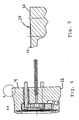
- the angled portion of the adjacent surface of the pressure sensor unit and/or the body part is shown in further details in Figs. 4 and 5 and in Figs. 6 and 7 .
- Fig. 4 the pressure sensor unit 4 is shown isolated from the body part1, and in Fig. 5 , an enlarged view of the encircled part 'A' showing the surface 22 of the pressure sensor unit is shown.
- the surface 22 comprises surface portion 24 having an inclination of 2.3 degree to the surface portion 25.
- a wedge-shaped gap is formed between the surface portion 24 and an adjacent surface portion of the body part 1.
- Fig 6 the body part 1 is shown isolated from the pressure sensor unit 4 and in Fig. 7 , an enlarged view of the encircled part A shows the assembling surface 19 of the body part 1.
- the assembling surface 19 comprises a surface portion 20 having an inclination of 2.3 degrees to the surface portion 18.
- a wedge-shaped gap is formed between the surface portion 20 and an adjacent surface portion of the sensor unit 4.
- the pressure sensor unit 4 and the body part 1 of Figs. 4 and 6 and the corresponding surface portions 20, 24 may be used in combination, or the pressure sensor unit or the body part may be combined with a component without any inclined surface portion.
- Figs. 8-9 show enlarged views of the assembling zone during assembling by welding.
- the melt 27 has joined the surface contact zone of the assembling zone
- the melt has joined the transition zone of the assembling zone, and the gap 26 is adjacent the hermetic joint zone formed by the welding.
Abstract
Description
- The present invention relates to a method of assembling a pressure transmitter for measuring the pressure of a system. In particular, the invention relates to a method of assembling a pressure transmitter of the kind provided with a body part forming a cavity, and a pressure sensor unit arranged in the cavity. The body part and the pressure sensor unit form in combination an assembling zone comprising a hermetic joint zone wherein the surfaces are joined hermetically, e.g. by welding.
- Transmitters of the above described kind are often applied in pressure systems which conduct a fluid flow, e.g. in vacuum systems or in refrigeration systems.
- Normally, the transmitters comprise a connection piece, for example with a screw threaded part or a welding flange for attachment to the pressure system. The connection piece typically forms part of a fluid communication conduit from the pressure system to a pressure sensor unit which is assembled hermetically with the connection piece. Normally, the sensor unit is inserted into the conduit to form a closure thereof, and subsequently it is fastened hermetically to the connection piece by welding. The transmitter may further have various electronic components for transforming the sensed pressure into a standardized electric signal.
- In the known transmitters, the connection piece comprises a cylindrical cavity with a circular cross-sectional shape and with an exactly fixed radial size in its full depth. The sensor, correspondingly, has the shape of a piston of a dimension fitting into the cylindrical cavity. During the manufacturing of the transmitter, the sensor unit is pressed into the cavity and subsequently, the connection piece and the sensor unit is welded together from the outside. In order to establish a temporarily fixed connection to maintain the sensor unit in a fixed position in the connection piece during welding, the dimensions of the sensor unit and the cavity are very close to each other to form an interference fit, and the sensor unit therefore has to be pressed into the cavity by use of force. This complicates the assembling work and requires narrow tolerances and thus more expensive components. Moreover, it has been found that gases caused by the welding process can be confined in the material and potentially lead to leakage between the connection piece and the sensor. The confining of the gases is intensified by the interference fit between the connection piece and the sensor.
-
US 5,691,479 discloses a pressure transducer comprising a disc-shaped pressure sensor component welded to a pressure supplying body. Sensor component and supplying body are arranged within a cavity formed in cap-like part of the transducer. In order to achieve a uniform pressure distribution, the space between the supplying body and the cap-like part and between the sensor component and the cap-like part is filled with casting resin material. -
WO 2005/017479 A1 falls within the terms of Art.54(3) EPC and discloses a tire pressure sensor, where a surface acoustic wave sensor element is mounted on a unit base element. The base element is inserted and hermetically joined to a relative flexible cover part by welding. The cover part comprises a sensing diaphragm with a central dimple being in contact with and preloading the sensing element.US 4 006 640 discloses a pressure to current transmitter that has an internal fill fluid chamber separated from a process fluid by a diaphragm and backup plate. - It is an object of the invention to provide an improved method of assembling a pressure transmitter as defined in claim 1. Accordingly, the invention provides a method of assembling a pressure transmitter of the kind described in the introduction, wherein the assembling zone further comprises a gap zone adjacent the hermetic joint zone in which gap zone the pressure sensor unit and the body part are mutually dimensioned to form a gap between adjacent surfaces of the pressure sensor unit and the body part. Since the parts are dimensioned to form a gap adjacent the hermetic joint zone, gases, e.g. from a welding or gluing process will be allowed to drain away, and the risk of getting welding pores from confined gases or the risk of getting large hardening durations for a gluing process is reduced. Accordingly, the pressure transmitter may be improved.
- The pressure sensor unit is of the kind generally known for measuring pressure, i.e. of the kind having a cavity with a bottom portion and a sidewall extending upwardly towards an opening which is sealed with a flexible membrane, the cavity of the sensor unit is typically filled with a liquid pressure transferring oil, and the cavity further houses a pressure sensitive electronic component.
- The body part forms a connection piece for connecting the pressure transmitter to a pressure system, e.g. via screw threads or via a welding flange, and may further house electronic components or have fixation means for fixating electronic components to the pressure transmitter. Such electronic components may be used for transforming the sensed pressure into a standardized electric signal.
- The gap may preferably be in the size of up to 0.1 mm, such as in the size of 0.04 mm. The adjacent surfaces are the surfaces of the pressure sensor unit and the body parts which are adjacent when the pressure sensor unit is arranged in the body part. Prior to the hermetic joining, e.g. by welding, the adjacent surfaces are the surfaces of the pressure sensor unit and the body part in the entire assembling zone. After the hermetic joining, the adjacent surfaces are possibly only the surfaces of the pressure sensor unit and the body part in the gap zone since the two components may be melted together in the remaining parts of the assembling zone.
- The gap is defined by at least one of the pressure sensor unit and the body part having a recessed or elevated surface part to form the gap between the pressure sensor unit and the body part when the pressure sensor unit and the body part are finally joined hermetically.
- The body part could e.g. be a connection piece, e.g. with screw threads or with a welding flange for attachment to a pressure system. The cavity in the body part forms part of a through going conduit extending from the pressure sensor to the point wherein the body part is attached to the pressure system. The pressure sensor unit is inserted into, and hermetically fastened to the cavity to form a closure thereof.
- The assembling zone further comprises a surface contact zone wherein the sensor unit and body are mutually dimensioned to form contact between adjacent surfaces when the sensor unit is arranged in the cavity, and prior to the hermetic joining. The contact zone facilitates easy assembling of the parts. During the assembling, the pressure sensor unit is inserted into the cavity and pressed down therein until a required position of the pressure sensor unit in relation to the body part is reached. At this point, the adjacent surfaces engage each other in the contact zone and thus establish a preliminary fixation of the two parts, which preliminary fixation may facilitate final assembling by welding. The contact zone may e.g. have a length corresponding to between 1/6 and 1/2 of the length of the assembling zone, i.e. the pressure sensor unit and body part may form an interference fit over approximately 1/6 to 1/2 of the total length of hermetic joint zone, i.e. e.g. the length of the welding. The actual size depends on the required strength of the joint between the pressure sensor unit and the body part. The pressure sensor unit gets more solidly attached to the body part the longer the hermetic joint zone is. Adjacent the surface contact zone, it may be an advantage to have a gap in the size of up to 0.1 mm. During assembling by welding, a gap of this size on one hand facilitates transportation of gases away from the hermetic joint zone, and on the other hand allows the use of a welding process to join the pressure sensor unit and the body part across the gap. Outside the hermetic joint zone the gap may exceed the 0.1 mm.
- The assembling zone may further comprise a transition zone extending between the surface contact zone and the gap zone. In the transition zone, the pressure sensor unit and body part are mutually dimensioned to form a gap of a size which varies along a path from the contact zone towards the gap zone. Adjacent the contact zone, the gap could equal 0 mm or closely equal zero mm and adjacent the gap zone, the gap could equal, or closely equal the gap which is found in the gap zone, e.g. varying from 0 mm towards 0.02-0.12 mm The gap may vary linearly, i.e. with a fixed increase for a fixed step along the path from the surface contact zone towards the gap zone. The transition zone may preferably be formed between smoothly inclined adjacent surfaces of the pressure sensor unit and the body part or by an inclined surface of at least one of the pressure sensor unit and the body part. Due to the transition zone, the pressure sensor unit is wedged into sealing contact with the body part while the pressure sensor unit is pressed down into the cavity, and the necessity of narrow tolerances between the pressure sensor unit and the body part is therefore reduced. The transition zone may be formed by a surface of at lease one of the pressure sensor unit and the body part, said surface forming an angle to an adjacent surface portion of the other one of the pressure sensor unit and the body part when the pressure sensor unit is arranged in the cavity. The angle may be of a size which ensures that the corresponding gap between the surfaces is in the size of up to 0.1 mm. The transition zone may thus define a wedge-shaped gap which gap further enhances draining of the gases away from the assembling zone, and thus further reduces the risk of getting welding pores from confined gases. During the final hermetic assembling process, e.g. by welding or gluing, at least a part of the gap in the transition zone may be eliminated by the melt or glue deriving from the final assembling process.
- The body part and/or the pressure sensor unit may preferably be made from any metallic material and preferably be assembled by WIG (Wolfram Inert Gas) welding.
- Preferably, the cavity is cylindrical and the pressure sensor unit has the shape of a piston. In this situation, the adjacent surfaces are constituted by the peripheral inner and outer surfaces of the cylinder and piston, respectively. In order to provide a transition zone with a wedge-shaped gap between the contact surfaces, the contact surface of at least one of the pressure sensor unit and the body part may have at least two surface sections forming an angle to each other.
- The cavity of the body part form part of a conduit from a first end to an opposite second end of the body part. If the body part forms a connection piece for connecting the transmitter to a pressure system, e.g. a refrigeration system, the first end could have fastening means, e.g. screw threads or a welding flange for connecting the body part to a pressure system. The cavity and the contact surfaces have circular shapes in a cross section perpendicular to the conduit, and in order to provide a hermetic sealing connection between the pressure sensor unit and the body part, the pressure sensor unit may be attached to the body part by welding and hereafter forms a closure which seals the second end of the conduit.
- A pressure sensor unit for a pressure transmitter assembled according to the invention comprises a cavity with a bottom portion and a sidewall extending upwardly towards an opening which is sealed with a flexible membrane, wherein an outer surface of the sidewall forms an assembling surface which, during a final assembling step, is assembled with a corresponding assembling surface of the associated pressure transmitter body part. The assembling surface may comprise at least two non-parallel surface portions, i.e. wherein the surface portions form an angle α to each other over a section of the assembling area, wherein 0<α<90 degrees, or preferably 0<α<3 degrees, such as α = 2.3 degrees, or so that the angle between the surfaces provides a gap between the surfaces in the size of up to 0.1 mm.
- A body part for a pressure transmitter assembled according to the invention forms a cavity having an opening for receiving a pressure sensor unit, and in the cavity, an assembly surface which, during a final assembling step, is assembled with a corresponding assembling surface of the associated pressure sensor unit. The assembling surface may comprise at least two non-parallel surface portions, i.e. wherein the surface portions form an angle α to each other over a section of the assembling area, wherein 0<α<90 degrees, or preferably 0<α<3 degrees, such as α = 2.3 degrees, or so that the angle provides a gap between the pressure sensor unit and the body part which gap is in the size of up to 0.1 mm.
- In the following, the invention will be described in further details with reference to the drawing in which
-
Fig. 1 shows a cross-sectional view of a pressure transmitter in an exploded view, -
Fig. 2 shows a view of the pressure transmitter inFig. 1 in an assembled view, -
Fig. 3 shows an enlarged view of the assembling zone of the pressure transmitter, -
Fig. 4 shows a pressure sensor unit for the pressure transmitter, -
Fig. 5 shows an enlarged view of an assembly surface of the pressure sensor unit inFig. 4 , -
Fig. 6 shows a body part for the pressure transmitter, -
Fig. 7 shows an enlarged view of an assembly surface of the body part inFig. 6 , and -
Figs. 8-9 show enlarged views of the assembling zone during assembling by welding. -
Fig. 1 shows a pressure transmitter with a body part 1 forming acavity 2 having an opening 3 for receiving apressure sensor unit 4. InFig. 2 , the pressure sensor unit is arranged in the cavity ready to be finally hermetically assembled in the assemblingzone 5 viaadjacent surfaces 6, 7 (inFig. 1 ) of the body part 1 and thepressure sensor unit 4. As best seen in the enlarged view ofFig. 3 , thepressure sensor unit 4 and the body part 1 are mutually dimensioned to form a gap 8 in the assembling zone when the pressure sensor unit is arranged in the cavity. InFig. 3 , the parts are not yet assembled hermetically. The assembling zone comprises asurface contact zone 10 wherein thepressure sensor unit 4 and the body 1 are mutually dimensioned to form contact between the adjacent surfaces while they are being assembled, a gap zone 11 wherein the pressure sensor unit and the body part are mutually dimensioned to form a gap in the size of 0.1 mm between the adjacent surfaces, and atransition zone 12. The surface contact zone supports manufacturing by fixating thepressure sensor unit 4 preliminary in the body part 1 until final assembling is conducted by welding, and the transition zone provides a wedge-shapedgap 13 between the pressure sensor unit and the body part. The size of the wedge-shaped gap varies from 0 to the size of the gap in the gap zone. In the transition zone, at least one of the pressure sensor unit and the body part has a surface forming an angle to an adjacent surface of the other one of the pressure sensor unit and body part. The angled portion of the adjacent surface of the pressure sensor unit and/or the body part is shown in further details inFigs. 4 and 5 and inFigs. 6 and 7 . - In
Fig. 4 , thepressure sensor unit 4 is shown isolated from the body part1, and inFig. 5 , an enlarged view of the encircled part 'A' showing thesurface 22 of the pressure sensor unit is shown. Thesurface 22 comprisessurface portion 24 having an inclination of 2.3 degree to thesurface portion 25. When thepressure sensor unit 4 is arranged in the body part 1, a wedge-shaped gap is formed between thesurface portion 24 and an adjacent surface portion of the body part 1. - In
Fig 6 , the body part 1 is shown isolated from thepressure sensor unit 4 and inFig. 7 , an enlarged view of the encircled part A shows the assemblingsurface 19 of the body part 1. The assemblingsurface 19 comprises asurface portion 20 having an inclination of 2.3 degrees to thesurface portion 18. When thepressure sensor unit 4 is arranged in the body part 1, a wedge-shaped gap is formed between thesurface portion 20 and an adjacent surface portion of thesensor unit 4. - The
pressure sensor unit 4 and the body part 1 ofFigs. 4 and6 and thecorresponding surface portions -
Figs. 8-9 show enlarged views of the assembling zone during assembling by welding. InFig. 8 , the melt 27 has joined the surface contact zone of the assembling zone, and inFig. 9 , the melt has joined the transition zone of the assembling zone, and thegap 26 is adjacent the hermetic joint zone formed by the welding.
Claims (8)
- A method of assembling a pressure transmitter comprising the steps in the following sequence:a) -providing a body part (1) forming a cavity (2) and having an opening (3) for receiving a pressure sensor unit (4), and in the cavity (2), an assembling surface (6, 19), wherein the cavity (2) forms part of a conduit from a first end to be connected to an associated pressure system to an opposite second end housing the pressure sensor unit (4),b) -providing a pressure sensor unit (4) having a unit cavity, a bottom portion and a sidewall extending upwardly from the bottom portion towards an opening which is sealed with a flexible membrane, the unit cavity housing a pressure sensitive electronic component, wherein an outer surface of the sidewall forms an assembling surface (7, 22) adapted to be assembled with the corresponding assembling surface (6, 19) of the body part,c) -inserting the pressure sensor unit (4) in the cavity (2) of the body part (1) to form an assembling zone (5) between the adjacent assembling surfaces (6, 7, 19, 22) of the body part (1) and the pressure sensor unit (4), the assembling zone (5) comprising a surface contact zone (10), where contact is formed between adjacent surface portions (18, 25) of the body part (1) and the pressure sensor unit (4), and a gap zone (11), where a gap (8, 26) of a predetermined and substantially uniform size is formed between adjacent surface portions (20, 24) of the body part (1) and the pressure sensor unit (4), and where the gap (8, 26) is formed by a recess in at least one of the assembling surfaces (6, 7, 19, 22),d) -hermetically joining the body part (1) and the pressure sensor unit (4) by welding.
- A method according to claim 1, wherein the gap (8, 26) is in the size of up to 0.1mm, such as in the size of 0.04mm.
- A method according to claim 2, wherein a melt (27) from the welding process joins the surface contact zone (10) and at least a part of the gap zone (11).
- A method according to any of the preceding claims, wherein the assembling zone (5) comprises a transition zone (12) extending between the surface contact zone (10) and the gap zone (11), and wherein the pressure sensor unit (4) and body part (1) are dimensioned to form a wedge-shaped gap (13) when the sensor unit is arranged in the cavity (2) prior to the hermetic joining.
- A method according to claim 4, wherein adjacent surfaces (6, 7, 19, 22) of the pressure sensor unit (4) and the body part (1) are formed with an angle a to each other over a section of the assembling zone (5), wherein 0<α<3 degrees when the pressure sensor unit (4) is arranged in the cavity (2) prior to the hermetic joining.
- A method according to claim 1, wherein the cavity (2) is provided cylindrical and the pressure sensor unit (4) is provided with a shape of a piston, and wherein the adjacent surfaces (6, 7, 19, 22) are constituted by the peripheral inner and outer surfaces of the cylinder and piston, respectively.
- A method according to claim 1, wherein the adjacent surfaces of the body part (1) and pressure sensor unit (4) have circular shapes in a cross section perpendicular to the conduit when the pressure sensor unit (4) is arranged in the cavity (2) prior to hermetic joining.
- A method according to any of the preceding claims, wherein the body part (1) is formed with a connection piece for connecting the transmitter to the pressure system.
Applications Claiming Priority (2)
| Application Number | Priority Date | Filing Date | Title |
|---|---|---|---|
| DKPA200400141 | 2004-01-30 | ||
| DK200400141 | 2004-01-30 |
Publications (2)
| Publication Number | Publication Date |
|---|---|
| EP1560012A1 EP1560012A1 (en) | 2005-08-03 |
| EP1560012B1 true EP1560012B1 (en) | 2010-06-02 |
Family
ID=34639208
Family Applications (1)
| Application Number | Title | Priority Date | Filing Date |
|---|---|---|---|
| EP05075183A Active EP1560012B1 (en) | 2004-01-30 | 2005-01-25 | A pressure transmitter |
Country Status (5)
| Country | Link |
|---|---|
| US (1) | US7201058B2 (en) |
| EP (1) | EP1560012B1 (en) |
| CN (1) | CN100567924C (en) |
| AT (1) | ATE470138T1 (en) |
| DE (1) | DE602005021565D1 (en) |
Families Citing this family (9)
| Publication number | Priority date | Publication date | Assignee | Title |
|---|---|---|---|---|
| CN102175385A (en) * | 2011-03-15 | 2011-09-07 | 中环天仪股份有限公司 | Intelligent pressure sensor |
| JP6605449B2 (en) * | 2014-03-27 | 2019-11-13 | シチズンファインデバイス株式会社 | Combustion pressure sensor and manufacturing method thereof |
| US9746390B2 (en) | 2015-02-26 | 2017-08-29 | Sensata Technologies, Inc. | Microfused silicon strain gauge (MSG) pressure sensor package |
| CN107290099B (en) | 2016-04-11 | 2021-06-08 | 森萨塔科技公司 | Pressure sensor, plug for a pressure sensor and method for producing a plug |
| EP3236226B1 (en) | 2016-04-20 | 2019-07-24 | Sensata Technologies, Inc. | Method of manufacturing a pressure sensor |
| US10545064B2 (en) | 2017-05-04 | 2020-01-28 | Sensata Technologies, Inc. | Integrated pressure and temperature sensor |
| US10323998B2 (en) | 2017-06-30 | 2019-06-18 | Sensata Technologies, Inc. | Fluid pressure sensor |
| US10724907B2 (en) | 2017-07-12 | 2020-07-28 | Sensata Technologies, Inc. | Pressure sensor element with glass barrier material configured for increased capacitive response |
| US10557770B2 (en) | 2017-09-14 | 2020-02-11 | Sensata Technologies, Inc. | Pressure sensor with improved strain gauge |
Citations (2)
| Publication number | Priority date | Publication date | Assignee | Title |
|---|---|---|---|---|
| US4006640A (en) * | 1976-02-06 | 1977-02-08 | Honeywell Inc. | Seal for process pressure to current transmitter |
| WO2005017479A1 (en) * | 2003-08-05 | 2005-02-24 | Honeywell International Inc. | Sensor with molded sensor diaphragm cover |
Family Cites Families (8)
| Publication number | Priority date | Publication date | Assignee | Title |
|---|---|---|---|---|
| US4930929A (en) * | 1989-09-26 | 1990-06-05 | Honeywell Inc. | Glass tube/stainless steel header interface for pressure sensor |
| DE4244459C1 (en) * | 1992-12-23 | 1994-05-11 | Siemens Ag | Pressure transmitter |
| JP3199103B2 (en) | 1995-01-06 | 2001-08-13 | 横河電機株式会社 | Differential pressure measuring device |
| US6122154A (en) | 1997-04-24 | 2000-09-19 | Damerow; Robert William | Motor starting device and protector module with motor starter cut-out switch |
| US6542062B1 (en) | 1999-06-11 | 2003-04-01 | Tecumseh Products Company | Overload protector with control element |
| US6647794B1 (en) * | 2002-05-06 | 2003-11-18 | Rosemount Inc. | Absolute pressure sensor |
| JP2004191128A (en) * | 2002-12-10 | 2004-07-08 | Pacific Ind Co Ltd | Semiconductor sensor and transmitter of tire state monitoring device |
| US7036381B2 (en) * | 2004-06-25 | 2006-05-02 | Rosemount Inc. | High temperature pressure transmitter assembly |
-
2005
- 2005-01-25 AT AT05075183T patent/ATE470138T1/en not_active IP Right Cessation
- 2005-01-25 EP EP05075183A patent/EP1560012B1/en active Active
- 2005-01-25 DE DE602005021565T patent/DE602005021565D1/en active Active
- 2005-01-27 US US11/044,963 patent/US7201058B2/en active Active
- 2005-01-29 CN CNB2005100509262A patent/CN100567924C/en active Active
Patent Citations (2)
| Publication number | Priority date | Publication date | Assignee | Title |
|---|---|---|---|---|
| US4006640A (en) * | 1976-02-06 | 1977-02-08 | Honeywell Inc. | Seal for process pressure to current transmitter |
| WO2005017479A1 (en) * | 2003-08-05 | 2005-02-24 | Honeywell International Inc. | Sensor with molded sensor diaphragm cover |
Also Published As
| Publication number | Publication date |
|---|---|
| CN100567924C (en) | 2009-12-09 |
| EP1560012A1 (en) | 2005-08-03 |
| US7201058B2 (en) | 2007-04-10 |
| DE602005021565D1 (en) | 2010-07-15 |
| ATE470138T1 (en) | 2010-06-15 |
| CN1648628A (en) | 2005-08-03 |
| US20050189428A1 (en) | 2005-09-01 |
Similar Documents
| Publication | Publication Date | Title |
|---|---|---|
| EP1560012B1 (en) | A pressure transmitter | |
| US3979565A (en) | Metal enclosed transducer assembly | |
| EP3128305B1 (en) | A hermetic pressure sensor | |
| KR100983814B1 (en) | Pressure sensor having a metal diaphragm responsive to pressure | |
| US6978681B2 (en) | Pressure sensor | |
| US10260978B2 (en) | Pressure detection unit and pressure sensor using the same | |
| US10260979B2 (en) | Pressure detection unit, pressure sensor using the same, and method of manufacturing pressure detection unit | |
| US6658940B2 (en) | Pressure sensor, and a method for mounting it | |
| US7134345B2 (en) | Pressure transducer with one-piece housing | |
| US20010009059A1 (en) | Method and device for manufacturing pressure detecting apparatus | |
| US7665365B2 (en) | Pressure sensor and attachment structure of pressure sensor | |
| US6769308B1 (en) | Low-cost stainless steel pressure sensor assembly for a pneumatic valve | |
| JP3509627B2 (en) | Pressure detector | |
| JP4020014B2 (en) | Pressure sensor | |
| JP3835317B2 (en) | Pressure sensor | |
| JP2014095558A (en) | Connection component, and differential pressure/pressure transmitter | |
| US20220154880A1 (en) | Tank for pressurized gas | |
| JP2005214780A (en) | Pressure sensor | |
| JP2007275979A (en) | Welding method | |
| JP4155204B2 (en) | Pressure sensor | |
| JP2005207875A (en) | Pressure sensor | |
| JP3991808B2 (en) | Pressure sensor | |
| JP2006084293A (en) | Pressure sensor | |
| JPH0654270B2 (en) | Pressure measuring instrument | |
| JP2006184075A (en) | Pressure sensor |
Legal Events
| Date | Code | Title | Description |
|---|---|---|---|
| PUAI | Public reference made under article 153(3) epc to a published international application that has entered the european phase |
Free format text: ORIGINAL CODE: 0009012 |
|
| AK | Designated contracting states |
Kind code of ref document: A1 Designated state(s): AT BE BG CH CY CZ DE DK EE ES FI FR GB GR HU IE IS IT LI LT LU MC NL PL PT RO SE SI SK TR |
|
| AX | Request for extension of the european patent |
Extension state: AL BA HR LV MK YU |
|
| 17P | Request for examination filed |
Effective date: 20050919 |
|
| AKX | Designation fees paid |
Designated state(s): AT BE BG CH CY CZ DE DK EE ES FI FR GB GR HU IE IS IT LI LT LU MC NL PL PT RO SE SI SK TR |
|
| 17Q | First examination report despatched |
Effective date: 20061127 |
|
| 17Q | First examination report despatched |
Effective date: 20061127 |
|
| 17Q | First examination report despatched |
Effective date: 20061127 |
|
| GRAP | Despatch of communication of intention to grant a patent |
Free format text: ORIGINAL CODE: EPIDOSNIGR1 |
|
| GRAS | Grant fee paid |
Free format text: ORIGINAL CODE: EPIDOSNIGR3 |
|
| GRAA | (expected) grant |
Free format text: ORIGINAL CODE: 0009210 |
|
| STAA | Information on the status of an ep patent application or granted ep patent |
Free format text: STATUS: THE PATENT HAS BEEN GRANTED |
|
| AK | Designated contracting states |
Kind code of ref document: B1 Designated state(s): AT BE BG CH CY CZ DE DK EE ES FI FR GB GR HU IE IS IT LI LT LU MC NL PL PT RO SE SI SK TR |
|
| REG | Reference to a national code |
Ref country code: GB Ref legal event code: FG4D |
|
| REG | Reference to a national code |
Ref country code: CH Ref legal event code: EP |
|
| REG | Reference to a national code |
Ref country code: IE Ref legal event code: FG4D |
|
| REF | Corresponds to: |
Ref document number: 602005021565 Country of ref document: DE Date of ref document: 20100715 Kind code of ref document: P |
|
| REG | Reference to a national code |
Ref country code: NL Ref legal event code: VDEP Effective date: 20100602 |
|
| PG25 | Lapsed in a contracting state [announced via postgrant information from national office to epo] |
Ref country code: LT Free format text: LAPSE BECAUSE OF FAILURE TO SUBMIT A TRANSLATION OF THE DESCRIPTION OR TO PAY THE FEE WITHIN THE PRESCRIBED TIME-LIMIT Effective date: 20100602 Ref country code: SE Free format text: LAPSE BECAUSE OF FAILURE TO SUBMIT A TRANSLATION OF THE DESCRIPTION OR TO PAY THE FEE WITHIN THE PRESCRIBED TIME-LIMIT Effective date: 20100602 |
|
| LTIE | Lt: invalidation of european patent or patent extension |
Effective date: 20100602 |
|
| PG25 | Lapsed in a contracting state [announced via postgrant information from national office to epo] |
Ref country code: SI Free format text: LAPSE BECAUSE OF FAILURE TO SUBMIT A TRANSLATION OF THE DESCRIPTION OR TO PAY THE FEE WITHIN THE PRESCRIBED TIME-LIMIT Effective date: 20100602 Ref country code: AT Free format text: LAPSE BECAUSE OF FAILURE TO SUBMIT A TRANSLATION OF THE DESCRIPTION OR TO PAY THE FEE WITHIN THE PRESCRIBED TIME-LIMIT Effective date: 20100602 Ref country code: FI Free format text: LAPSE BECAUSE OF FAILURE TO SUBMIT A TRANSLATION OF THE DESCRIPTION OR TO PAY THE FEE WITHIN THE PRESCRIBED TIME-LIMIT Effective date: 20100602 |
|
| PG25 | Lapsed in a contracting state [announced via postgrant information from national office to epo] |
Ref country code: GR Free format text: LAPSE BECAUSE OF FAILURE TO SUBMIT A TRANSLATION OF THE DESCRIPTION OR TO PAY THE FEE WITHIN THE PRESCRIBED TIME-LIMIT Effective date: 20100903 Ref country code: CY Free format text: LAPSE BECAUSE OF FAILURE TO SUBMIT A TRANSLATION OF THE DESCRIPTION OR TO PAY THE FEE WITHIN THE PRESCRIBED TIME-LIMIT Effective date: 20100602 Ref country code: PL Free format text: LAPSE BECAUSE OF FAILURE TO SUBMIT A TRANSLATION OF THE DESCRIPTION OR TO PAY THE FEE WITHIN THE PRESCRIBED TIME-LIMIT Effective date: 20100602 |
|
| PG25 | Lapsed in a contracting state [announced via postgrant information from national office to epo] |
Ref country code: NL Free format text: LAPSE BECAUSE OF FAILURE TO SUBMIT A TRANSLATION OF THE DESCRIPTION OR TO PAY THE FEE WITHIN THE PRESCRIBED TIME-LIMIT Effective date: 20100602 Ref country code: EE Free format text: LAPSE BECAUSE OF FAILURE TO SUBMIT A TRANSLATION OF THE DESCRIPTION OR TO PAY THE FEE WITHIN THE PRESCRIBED TIME-LIMIT Effective date: 20100602 |
|
| PG25 | Lapsed in a contracting state [announced via postgrant information from national office to epo] |
Ref country code: BE Free format text: LAPSE BECAUSE OF FAILURE TO SUBMIT A TRANSLATION OF THE DESCRIPTION OR TO PAY THE FEE WITHIN THE PRESCRIBED TIME-LIMIT Effective date: 20100602 Ref country code: IS Free format text: LAPSE BECAUSE OF FAILURE TO SUBMIT A TRANSLATION OF THE DESCRIPTION OR TO PAY THE FEE WITHIN THE PRESCRIBED TIME-LIMIT Effective date: 20101002 Ref country code: CZ Free format text: LAPSE BECAUSE OF FAILURE TO SUBMIT A TRANSLATION OF THE DESCRIPTION OR TO PAY THE FEE WITHIN THE PRESCRIBED TIME-LIMIT Effective date: 20100602 Ref country code: PT Free format text: LAPSE BECAUSE OF FAILURE TO SUBMIT A TRANSLATION OF THE DESCRIPTION OR TO PAY THE FEE WITHIN THE PRESCRIBED TIME-LIMIT Effective date: 20101004 Ref country code: RO Free format text: LAPSE BECAUSE OF FAILURE TO SUBMIT A TRANSLATION OF THE DESCRIPTION OR TO PAY THE FEE WITHIN THE PRESCRIBED TIME-LIMIT Effective date: 20100602 Ref country code: SK Free format text: LAPSE BECAUSE OF FAILURE TO SUBMIT A TRANSLATION OF THE DESCRIPTION OR TO PAY THE FEE WITHIN THE PRESCRIBED TIME-LIMIT Effective date: 20100602 |
|
| PG25 | Lapsed in a contracting state [announced via postgrant information from national office to epo] |
Ref country code: IT Free format text: LAPSE BECAUSE OF FAILURE TO SUBMIT A TRANSLATION OF THE DESCRIPTION OR TO PAY THE FEE WITHIN THE PRESCRIBED TIME-LIMIT Effective date: 20100602 |
|
| PLBE | No opposition filed within time limit |
Free format text: ORIGINAL CODE: 0009261 |
|
| STAA | Information on the status of an ep patent application or granted ep patent |
Free format text: STATUS: NO OPPOSITION FILED WITHIN TIME LIMIT |
|
| PG25 | Lapsed in a contracting state [announced via postgrant information from national office to epo] |
Ref country code: DK Free format text: LAPSE BECAUSE OF FAILURE TO SUBMIT A TRANSLATION OF THE DESCRIPTION OR TO PAY THE FEE WITHIN THE PRESCRIBED TIME-LIMIT Effective date: 20100602 |
|
| 26N | No opposition filed |
Effective date: 20110303 |
|
| REG | Reference to a national code |
Ref country code: DE Ref legal event code: R097 Ref document number: 602005021565 Country of ref document: DE Effective date: 20110302 |
|
| PG25 | Lapsed in a contracting state [announced via postgrant information from national office to epo] |
Ref country code: MC Free format text: LAPSE BECAUSE OF NON-PAYMENT OF DUE FEES Effective date: 20110131 |
|
| REG | Reference to a national code |
Ref country code: CH Ref legal event code: PL |
|
| REG | Reference to a national code |
Ref country code: FR Ref legal event code: ST Effective date: 20110930 |
|
| REG | Reference to a national code |
Ref country code: IE Ref legal event code: MM4A |
|
| PG25 | Lapsed in a contracting state [announced via postgrant information from national office to epo] |
Ref country code: FR Free format text: LAPSE BECAUSE OF NON-PAYMENT OF DUE FEES Effective date: 20110131 Ref country code: CH Free format text: LAPSE BECAUSE OF NON-PAYMENT OF DUE FEES Effective date: 20110131 Ref country code: LI Free format text: LAPSE BECAUSE OF NON-PAYMENT OF DUE FEES Effective date: 20110131 |
|
| PG25 | Lapsed in a contracting state [announced via postgrant information from national office to epo] |
Ref country code: IE Free format text: LAPSE BECAUSE OF NON-PAYMENT OF DUE FEES Effective date: 20110125 |
|
| PG25 | Lapsed in a contracting state [announced via postgrant information from national office to epo] |
Ref country code: LU Free format text: LAPSE BECAUSE OF NON-PAYMENT OF DUE FEES Effective date: 20110125 |
|
| PG25 | Lapsed in a contracting state [announced via postgrant information from national office to epo] |
Ref country code: BG Free format text: LAPSE BECAUSE OF FAILURE TO SUBMIT A TRANSLATION OF THE DESCRIPTION OR TO PAY THE FEE WITHIN THE PRESCRIBED TIME-LIMIT Effective date: 20100902 Ref country code: TR Free format text: LAPSE BECAUSE OF FAILURE TO SUBMIT A TRANSLATION OF THE DESCRIPTION OR TO PAY THE FEE WITHIN THE PRESCRIBED TIME-LIMIT Effective date: 20100602 |
|
| PG25 | Lapsed in a contracting state [announced via postgrant information from national office to epo] |
Ref country code: HU Free format text: LAPSE BECAUSE OF FAILURE TO SUBMIT A TRANSLATION OF THE DESCRIPTION OR TO PAY THE FEE WITHIN THE PRESCRIBED TIME-LIMIT Effective date: 20100602 Ref country code: ES Free format text: LAPSE BECAUSE OF FAILURE TO SUBMIT A TRANSLATION OF THE DESCRIPTION OR TO PAY THE FEE WITHIN THE PRESCRIBED TIME-LIMIT Effective date: 20100913 |
|
| REG | Reference to a national code |
Ref country code: DE Ref legal event code: R082 Ref document number: 602005021565 Country of ref document: DE Representative=s name: KEIL & SCHAAFHAUSEN PATENTANWAELTE PARTGMBB, DE Ref country code: DE Ref legal event code: R082 Ref document number: 602005021565 Country of ref document: DE Representative=s name: KEIL & SCHAAFHAUSEN PATENT- UND RECHTSANWAELTE, DE |
|
| PGFP | Annual fee paid to national office [announced via postgrant information from national office to epo] |
Ref country code: GB Payment date: 20221201 Year of fee payment: 19 |
|
| PGFP | Annual fee paid to national office [announced via postgrant information from national office to epo] |
Ref country code: DE Payment date: 20221207 Year of fee payment: 19 |