CN100567924C - Pressure transmitter and make the method for pressure transmitter by sensor unit and main element - Google Patents
Pressure transmitter and make the method for pressure transmitter by sensor unit and main element Download PDFInfo
- Publication number
- CN100567924C CN100567924C CNB2005100509262A CN200510050926A CN100567924C CN 100567924 C CN100567924 C CN 100567924C CN B2005100509262 A CNB2005100509262 A CN B2005100509262A CN 200510050926 A CN200510050926 A CN 200510050926A CN 100567924 C CN100567924 C CN 100567924C
- Authority
- CN
- China
- Prior art keywords
- sensor unit
- pressure sensor
- main element
- cavity
- pressure
- Prior art date
- Legal status (The legal status is an assumption and is not a legal conclusion. Google has not performed a legal analysis and makes no representation as to the accuracy of the status listed.)
- Active
Links
Images


Classifications
-
- G—PHYSICS
- G01—MEASURING; TESTING
- G01L—MEASURING FORCE, STRESS, TORQUE, WORK, MECHANICAL POWER, MECHANICAL EFFICIENCY, OR FLUID PRESSURE
- G01L19/00—Details of, or accessories for, apparatus for measuring steady or quasi-steady pressure of a fluent medium insofar as such details or accessories are not special to particular types of pressure gauges
- G01L19/0007—Fluidic connecting means
- G01L19/0038—Fluidic connecting means being part of the housing
-
- G—PHYSICS
- G01—MEASURING; TESTING
- G01L—MEASURING FORCE, STRESS, TORQUE, WORK, MECHANICAL POWER, MECHANICAL EFFICIENCY, OR FLUID PRESSURE
- G01L19/00—Details of, or accessories for, apparatus for measuring steady or quasi-steady pressure of a fluent medium insofar as such details or accessories are not special to particular types of pressure gauges
- G01L19/14—Housings
- G01L19/141—Monolithic housings, e.g. molded or one-piece housings
-
- G—PHYSICS
- G01—MEASURING; TESTING
- G01L—MEASURING FORCE, STRESS, TORQUE, WORK, MECHANICAL POWER, MECHANICAL EFFICIENCY, OR FLUID PRESSURE
- G01L19/00—Details of, or accessories for, apparatus for measuring steady or quasi-steady pressure of a fluent medium insofar as such details or accessories are not special to particular types of pressure gauges
- G01L19/14—Housings
- G01L19/147—Details about the mounting of the sensor to support or covering means
Abstract
The invention provides a kind of pressure transmitter, it has the sensor unit of main element and sealed joint.Adjacent to sealing joints, gapped between the adjacently situated surfaces of main body and sensor unit, when main body and sensor unit by by welding assembling for example the time, this gap is more prone to assembling process, and makes gas get rid of from the sealing joints district to be more prone to.The present invention also provides a kind of main element, a kind of sensor unit part and a kind of device that comprises these parts of the forwarder that is used to make type above-mentioned.
Description
Technical field
The present invention relates to a kind of pressure transmitter of measuring system pressure.Especially, the present invention relates to such one type forwarder, it has the main element and the pressure transducer that is positioned in this cavity that form cavity.Main body and sensor unit are engaged on surface, place, sealing joints district hermetically in conjunction with forming an assembly section that comprises the sealing joints district, as, by welding.
Background technology
The forwarder of the above-mentioned type often is applied in the pressure system that the guiding fluid flows, as in vacuum system or in refrigeration system.
Normally, forwarder comprises a web member, for example has the screw flight or the weld flange that are used to be connected on the pressure system.Web member typically forms the part of fluid-transporting tubing from the pressure system to the pressure sensor unit, pressure sensor unit and web member sealing assembling.Normally, form a kind of closure therein, be sealingly secured to web member by welding it subsequently thereby sensor unit is inserted into pipeline.This forwarder can further comprise various electronic components, is used for the electric signal of standard that the pressure of induction is converted to.
In known forwarder, web member comprises a columniform cavity, and it has circular cross sectional shape, and has the radius size of strict conformance on its entire depth.Correspondingly, sensor has the shape that its diameter adapts to the piston of cylindrical cavity.In the process of processing forwarder, sensor unit is pressed in the cavity, subsequently, welds together from the outside web member and sensor unit.In order in welding process, to set up a temporary fixed connection sensor unit is remained on the fixed position in the web member, the diameter of sensor unit and cavity is very close to each other, thereby form a kind of interference engagement (interference fit), so sensor unit need use external force to be pressed in the cavity.Make the assembly work complexity like this, and need narrow tolerance, need expensive element thus.And, also find can be kept in detention in the material, and cause the leakage between web member and the sensor potentially by the gas that welding process produces.The confinement connected piece of gas and the interference engagement (interference fit) between the sensor are strengthened.
Summary of the invention
An object of the present invention is to provide a kind of improved pressure transmitter.Therefore, first aspect, the invention provides the pressure transmitter that a kind of this paper begins the type of describing, wherein the assembly section further comprises the interstitial area adjacent to the sealing joints district, sensor unit and main body are cut mutually in this interstitial area, thereby form a gap between the adjacently situated surfaces of sensor unit and main body.Be cut the gap that forms adjacent to the sealing joints district owing to each assembly, therefore, the gas that comes from for example welding or the gummed process will be drained gradually, has reduced owing to being produced the dangerous of welding pore by confinement gas or reducing the danger that produces the long quenching cycle in the gummed process.Therefore, this pressure transmitter can be modified.
Sensor unit can be the type known to gaging pressure general, promptly, has the cavity that has bottom surface portions and towards the type of a upwardly extending sidewall of opening, this opening is sealed by a kind of flexible membrane, the cavity of sensor unit typically full of liquid pressure transmits oil, and this cavity further holds the pressure sensitive electronic component.
Main body can form a kind of web member that is used for pressure transmitter is connected to pressure system, for example, by screw flight or by weld flange, and can further hold electronic component or have the stationary installation that is used for electronic component is fixed to pressure transmitter.Such electronic component can be used for the pressure of induction is converted to the standard electric signal.
The size in gap preferably mostly is most 0.1mm, is 0.04mm such as size.Adjacently situated surfaces is the surface of sensor unit and main element, and they are adjacent when sensor unit is placed in the main body.Before sealing joints was as welding, adjacently situated surfaces was sensor unit and the main body surface in whole assembly section.After sealing joints, adjacently situated surfaces may be sensor unit and the surface of main body in interstitial area, because these two elements may be melted in together in the remainder of assembly section.
The gap can by sensor unit and have in the main body of recessed or convex surfaces part at least one limit, when sensor unit and main body are finally engaged hermetically, between sensor unit and main body, to form the gap.
Main element can for example be a kind of web member that is used to be connected to pressure system, for example has screw flight or has weld flange.The main element cavity can form the perforation pipe section, and this pipeline extends in the point that this is connected to pressure system from pressure transducer.Pressure sensor unit is inserted into, and is sealingly secured to cavity to form a kind of closure therein.
The assembly section can further comprise surperficial contact region, and sensor unit and main body are formed to each other and are placed in the cavity and before sealed engagement when sensor unit, is in surperficial contact region to form contact between the adjacently situated surfaces.The contact region makes the assembling of parts become easy.In assembling process, sensor unit is inserted in the cavity, and is depressed there up to reaching the desired position of a sensor unit with respect to main body.In this, adjacently situated surfaces is engaged with each other on the contact region, forms the preliminary fixing of two parts thus, and this is tentatively fixed and can make final assembling by welding become easy.The contact region for example can have corresponding to assembly section length 1/6 to 1/2 between length, that is, sensor unit and main body can form interference engagement on about 1/6 to 1/2 length of sealed engagement district total length, that is, Han Jie length for example.Physical size depends on the required length of seam between sensor unit and the main body.Sealing joints district long pass sensor cell more is attached on the main body just firm more.Adjacent to surperficial contact region, having a size is favourable smaller or equal to the gap of 0.1mm.In the assembling process by welding, this size gap makes gas send out from the sealing joints district on the one hand and becomes easily, allows to use welding process to come along engage transducer unit, gap and main body on the other hand.The gap can surpass 0.1mm outside the sealing joints district.
The assembly section can further be included in the zone of transition of extending between surperficial contact region and the interstitial area.In zone of transition, sensor unit and main body are formed to mutually and form a gap, the size in this gap along from the contact region towards the path change of interstitial area.Place, contiguous contact region, this gap can equal 0mm or near equaling 0mm, place, adjacent gap district, this gap can equal or the approaching gap that equals to find in interstitial area, as changing to 0.02-0.12mm from 0mm.This gap can linear change, that is, with fixing amplitude along fixedly increasing from the path of surperficial contact region to interstitial area.Zone of transition can preferably be formed on sensor unit and main body along between the sliding inclination adjacently situated surfaces, or form by at least one the inclined surface in sensor unit and the main body.Because the existence of zone of transition, sensor unit is contacting with the main element sealing of wedge-type when sensor unit is pressed into cavity, has therefore also just reduced the necessity of narrow tolerance between sensor unit and the main element.Zone of transition can be formed by at least one the surface in sensor unit and the main body, when sensor unit is placed into cavity, described surface with respect in sensor unit and the main body another adjacently situated surfaces part shape at an angle.The size of this angle can guarantee that the respective clearance between the surface is in the range of size smaller or equal to 0.1mm.This zone of transition can limit a wedge gap like this, and this gap further strengthens the eliminating of gas from the assembly section, and further reduces the danger that produces the welding pore owing to by confinement gas thus.In last sealing assembling process, as, by welding or gummed, at least a portion in the gap in the zone of transition can be eliminated by the fused mass or the adhesive that are produced by last assembling process.
Main body and/or sensor unit can preferably be made by any metal material, and preferably by WIG (tungsten inert gas) welding assembling.
Preferably, cavity is cylindric, and sensor unit has piston-shaped.In this case, adjacently situated surfaces is respectively by the peripheral inside and outside surface composition of cylinder and piston.For the zone of transition that provides to have wedge gap between surface in contact, the surface in contact of at least one can have at least two shape surface portions at an angle to each other in sensor unit and the main body.
In a preferred embodiment of the invention, the cavity of main body forms pipe section from first end of main element to the second relative end.If main body forms a web member that is used for forwarder is connected to pressure system such as refrigeration system, first end can have stationary installation, and for example screw flight or weld flange are used for main body is connected to pressure system.Cavity and surface in contact have round-shaped in the xsect perpendicular to pipeline, be tightly connected in order between sensor unit and main body, to provide, sensor unit can be connected by welding to main element, and forms a kind of closure thus, second end of this closing seam pipeline.
Second aspect, the present invention provides pressure sensor unit for pressure transmitter, described sensor unit comprises the cavity that has bottom surface portions and towards a upwardly extending sidewall of opening, this opening is sealed by flexible membrane, wherein the outside surface of sidewall forms fitting surface, in last installation step, the corresponding fitting surface assembling of a fitting surface and a pressure transmitter main element that links, it is characterized in that fitting surface comprises at least two nonparallel surface portions, promptly, wherein shape is at an angle alpha each other on a cross section of assembly area for surface portion, wherein 0<α<90 ° make that perhaps the angle between the surface provides a gap smaller or equal to the range of size of 0.1mm between the surface.
The third aspect, the present invention provides a main element for pressure transmitter, described main element forms the cavity with opening, cavity is used to receive pressure transducer, in cavity, fitting surface is assembled together with the corresponding fitting surface of the sensor that links in last installation step, it is characterized in that, fitting surface comprises at least two nonparallel surface portions, promptly, wherein shape is at an angle alpha each other on the cross section of assembly area for surface portion, 0<α<90 ° wherein perhaps are preferably 0<α<3 °, such as α=2.3 °, perhaps make this angle that a gap is provided between sensor unit and main body, this gap is within the scope smaller or equal to 0.1mm.
Fourth aspect the invention provides a kind of assembling device that is used to constitute pressure transmitter, and described device comprises
Pressure sensor unit, it comprises the cavity that has bottom surface portions and towards a upwardly extending sidewall of opening, this opening is sealed by a kind of flexible membrane, wherein the outside surface of sidewall forms a fitting surface, its in the end be assembled together with the corresponding fitting surface of the pressure transmitter main element that links in the installation step and
Main element, its formation contain the cavity that is useful on the opening that receives pressure transducer, and in cavity, fitting surface is assembled together with the fitting surface of sensor in last installation step,
It is characterized in that when sensor unit was placed in the cavity sealing assembling, sensor unit and main body were formed to each other in the part of fitting surface at least and form the gap.That is, form the gap in the part on the surface that in welding process, is engaged by for example fused mass.
The feature of any description relevant with first aspect present invention can combine with fourth aspect with of the present invention second, third.
Description of drawings
Below, will be described in further detail with reference to accompanying drawing the present invention, wherein,
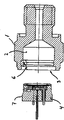
Fig. 1 is illustrated in the cross-sectional view of pressure transmitter in the exploded view,
Fig. 2 represents the view of the pressure transmitter of Fig. 1 in the wiring layout,
Fig. 3 represents the zoomed-in view of pressure transmitter assembly section,
Fig. 4 represents the pressure sensor unit of pressure transmitter,
The zoomed-in view of pressure sensor unit assembly surface in Fig. 5 presentation graphs 4,
Fig. 6 represents the main element of pressure transmitter,
The zoomed-in view of main element fitting surface in Fig. 7 presentation graphs 6,
Fig. 8-9 is illustrated in the zoomed-in view by assembly section in the welding assembling process.
Embodiment
Fig. 1 represents pressure transmitter, and it has the main element 1 that is formed with cavity 2, and cavity 2 has an opening 3, is used to receive pressure sensor unit 4.In Fig. 2, pressure sensor unit is placed in the cavity, and preparation is assembled by finally sealed ground by the adjacently situated surfaces 6,7 (among Fig. 1) of main body 1 and sensor unit 4 in assembly section 5.Can be seen in the zoomed-in view as Fig. 3 that when sensor unit was placed in the cavity, sensor unit 4 and main body 1 were formed to each other and form gap 8 in the assembly section.In Fig. 3, parts also do not have sealed assembling.The assembly section comprises a surperficial contact region 10, an interstitial area 11 and a zone of transition 12, wherein when sensor unit 4 and main body 1 are assembled, be formed to each other and between adjacently situated surfaces, form contact, be formed to the gap that between adjacently situated surfaces, forms 0.1mm at interstitial area 11 places each other at 10 places, surperficial contact region.By sensor unit 4 tentatively is fixed in the main body 1, surperficial contact region supports processing up to carrying out last assembling by welding, and zone of transition provides the gap 13 of a wedge shape between sensor unit and main body.The size of wedge gap changes between the gap size of spacer region 0.In zone of transition, at least one in sensor unit and the main body have a surface with respect in sensor unit and the main body another adjacently situated surfaces shape at an angle.The angled part of the adjacently situated surfaces of sensor unit and/or main body Fig. 4,5 and Fig. 6,7 in represented in further detail.
In Fig. 4, expression breaks away from the sensor 4 of main body 1, in Fig. 5, the zoomed-in view of drawing circle part ' A ' on the surface 22 of expression sensor unit is shown.Surface 22 comprises surface portion 24, and this surface portion 24 has 2.3 ° degree of tilt with respect to surface portion 25.When sensor unit 4 is placed in the main body 1, between the adjacently situated surfaces part of surface portion 24 and main body 1, form wedge gap.
In Fig. 6, the main body 1 of expression separating sensor unit 4, in Fig. 7, the zoomed-in view of drawing the circle part A is represented the assembly surface 19 of main body 1.Assembly surface 19 comprises surface portion 20, and this surface portion 20 has 2.3 ° degree of tilt with respect to surface portion 18.When sensor unit 4 is placed in the main body 1, between the adjacently situated surfaces part of surface portion 20 and sensor unit 4, form wedge gap.
Fig. 8-9 is illustrated in the zoomed-in view of assembly section in the process of assembling by welding.In Fig. 8, the surperficial contact region in fused mass 25 link pack areas, in Fig. 9, the zone of transition of fused mass link pack area, gap 26 is adjacent to the sealing joints district that forms by welding.
Claims (12)
1, a kind of pressure transmitter, it has the main element (1) that is formed with cavity (2) and is placed on pressure sensor unit (4) in the cavity (2), its cavity (2) forms pipe section from first end that is connected to the pressure system that links to the second relative end that holds described pressure sensor unit (4), and wherein said pressure sensor unit (4) comprises a cavity, bottom surface portions and one from described bottom surface portions towards a upwardly extending sidewall of opening, described opening is sealed by flexible membrane, the included cavity of described pressure sensor unit (4) holds the electronic component of pressure sensitive, main element (1) and pressure sensor unit (4) are united assembly section that comprises the sealing joints district of formation, it is characterized in that, assembly section (5) further comprises the spacer region (11) adjacent to the sealing joints district, pressure sensor unit in this spacer region (4) and main element (1) are formed to the adjacently situated surfaces (6 at pressure sensor unit (4) and main element (1) each other, 7,19,22) form gap (8 between, 26), wherein the formed cavity of main element (2) is columned, pressure sensor unit (4) has the shape of piston, and adjacently situated surfaces (6,7,19,22) form by the peripheral inside surface and the outside surface of cylinder and piston respectively.
2, forwarder according to claim 1, it is characterized in that, before sealed engagement, when pressure sensor unit was placed in the formed cavity of main element, pressure sensor unit and main element were formed to each other between the adjacently situated surfaces of assembly section and form the gap.
3, forwarder according to claim 1 and 2, it is characterized in that, the assembly section comprises surperficial contact region, when pressure sensor unit is placed in the formed cavity of main element, before sealed engagement, pressure sensor unit and main element are formed to each other and form contact between the adjacently situated surfaces of surperficial contact region.
4, forwarder according to claim 3, it is characterized in that, the assembly section is included in the zone of transition of extending between surperficial contact region and the spacer region, and when pressure sensor unit is placed in the formed cavity of main element, before sealed engagement, pressure sensor unit and main element are formed to the formation wedge gap each other.
5, forwarder according to claim 1 and 2, it is characterized in that, the adjacently situated surfaces of pressure sensor unit and main element on the cross section of assembly section each other shape at an angle alpha, when pressure sensor unit is placed in the formed cavity of main element, 0<α<3 degree.
6, forwarder according to claim 1 and 2 is characterized in that, the adjacently situated surfaces of at least one in pressure sensor unit and the main element comprises at least two surface portions of α form an angle with each other, before sealed engagement, and 0<α<3 degree.
7, forwarder according to claim 4 is characterized in that, by welding, pressure sensor unit engages hermetically with main element, and the fused mass composition surface contact region in the welding process.
8, forwarder according to claim 7 is characterized in that, the fused mass that produces in the welding process engages at least a portion of zone of transition.
9, forwarder according to claim 1 and 2, it is characterized in that, before sealed engagement, when pressure sensor unit was placed in the formed cavity of main element, the adjacently situated surfaces of main element and pressure sensor unit had round-shaped on the xsect perpendicular to pipeline.
10, forwarder according to claim 1 and 2 is characterized in that, main element forms and connects the web member of forwarder to pressure system.
11, the pressure sensor unit that is used for pressure transmitter according to claim 1, described pressure sensor unit comprise contain the cavity that has bottom surface portions, from described bottom surface portions towards a upwardly extending sidewall of opening, wherein said opening is sealed by flexible membrane, the outside surface of described sidewall forms assembly surface, described assembly surface is assembled together with the corresponding assembly surface of the main element of relevant pressure transmitter in last installation step, it is characterized in that described assembly surface comprises at least two nonparallel surface portions.
12, a kind of assembling device of making pressure transmitter according to claim 1, described device comprises:
Pressure sensor unit, it comprises bottom surface portions and towards a upwardly extending sidewall of opening, this opening seals with a kind of flexible membrane, wherein, the outside surface of sidewall forms assembly surface, its in last installation step, be assembled together with the corresponding assembly surface of the pressure transmitter main element that links and
The pressure transmitter main element, it forms the cavity with opening, and this cavity is used to receive pressure sensor unit, and in cavity, assembly surface is assembled together with the assembly surface of pressure sensor unit in last installation step,
It is characterized in that when pressure sensor unit is placed to when carrying out sealed engagement in the cavity, pressure sensor unit and main element are formed to each other between the part of assembly surface at least and form the gap.
Applications Claiming Priority (2)
| Application Number | Priority Date | Filing Date | Title |
|---|---|---|---|
| DKPA200400141 | 2004-01-30 | ||
| DKPA200400141 | 2004-01-30 |
Publications (2)
| Publication Number | Publication Date |
|---|---|
| CN1648628A CN1648628A (en) | 2005-08-03 |
| CN100567924C true CN100567924C (en) | 2009-12-09 |
Family
ID=34639208
Family Applications (1)
| Application Number | Title | Priority Date | Filing Date |
|---|---|---|---|
| CNB2005100509262A Active CN100567924C (en) | 2004-01-30 | 2005-01-29 | Pressure transmitter and make the method for pressure transmitter by sensor unit and main element |
Country Status (5)
| Country | Link |
|---|---|
| US (1) | US7201058B2 (en) |
| EP (1) | EP1560012B1 (en) |
| CN (1) | CN100567924C (en) |
| AT (1) | ATE470138T1 (en) |
| DE (1) | DE602005021565D1 (en) |
Families Citing this family (9)
| Publication number | Priority date | Publication date | Assignee | Title |
|---|---|---|---|---|
| CN102175385A (en) * | 2011-03-15 | 2011-09-07 | 中环天仪股份有限公司 | Intelligent pressure sensor |
| US10458328B2 (en) * | 2014-03-27 | 2019-10-29 | Citizen Finedevice Co., Ltd. | Welded combustion pressure sensor and method of manufacturing same |
| US9746390B2 (en) * | 2015-02-26 | 2017-08-29 | Sensata Technologies, Inc. | Microfused silicon strain gauge (MSG) pressure sensor package |
| CN107290099B (en) | 2016-04-11 | 2021-06-08 | 森萨塔科技公司 | Pressure sensor, plug for a pressure sensor and method for producing a plug |
| EP3236226B1 (en) | 2016-04-20 | 2019-07-24 | Sensata Technologies, Inc. | Method of manufacturing a pressure sensor |
| US10545064B2 (en) | 2017-05-04 | 2020-01-28 | Sensata Technologies, Inc. | Integrated pressure and temperature sensor |
| US10323998B2 (en) | 2017-06-30 | 2019-06-18 | Sensata Technologies, Inc. | Fluid pressure sensor |
| US10724907B2 (en) | 2017-07-12 | 2020-07-28 | Sensata Technologies, Inc. | Pressure sensor element with glass barrier material configured for increased capacitive response |
| US10557770B2 (en) | 2017-09-14 | 2020-02-11 | Sensata Technologies, Inc. | Pressure sensor with improved strain gauge |
Family Cites Families (10)
| Publication number | Priority date | Publication date | Assignee | Title |
|---|---|---|---|---|
| US4006640A (en) * | 1976-02-06 | 1977-02-08 | Honeywell Inc. | Seal for process pressure to current transmitter |
| US4930929A (en) * | 1989-09-26 | 1990-06-05 | Honeywell Inc. | Glass tube/stainless steel header interface for pressure sensor |
| DE4244459C1 (en) * | 1992-12-23 | 1994-05-11 | Siemens Ag | Pressure transmitter |
| JP3199103B2 (en) | 1995-01-06 | 2001-08-13 | 横河電機株式会社 | Differential pressure measuring device |
| US6122154A (en) | 1997-04-24 | 2000-09-19 | Damerow; Robert William | Motor starting device and protector module with motor starter cut-out switch |
| US6542062B1 (en) | 1999-06-11 | 2003-04-01 | Tecumseh Products Company | Overload protector with control element |
| US6647794B1 (en) * | 2002-05-06 | 2003-11-18 | Rosemount Inc. | Absolute pressure sensor |
| JP2004191128A (en) * | 2002-12-10 | 2004-07-08 | Pacific Ind Co Ltd | Semiconductor sensor and transmitter of tire state monitoring device |
| US6962084B2 (en) * | 2003-08-06 | 2005-11-08 | Honeywell International Inc. | Sensor with molded sensor diaphragm cover |
| US7036381B2 (en) * | 2004-06-25 | 2006-05-02 | Rosemount Inc. | High temperature pressure transmitter assembly |
-
2005
- 2005-01-25 DE DE602005021565T patent/DE602005021565D1/en active Active
- 2005-01-25 EP EP05075183A patent/EP1560012B1/en active Active
- 2005-01-25 AT AT05075183T patent/ATE470138T1/en not_active IP Right Cessation
- 2005-01-27 US US11/044,963 patent/US7201058B2/en active Active
- 2005-01-29 CN CNB2005100509262A patent/CN100567924C/en active Active
Also Published As
| Publication number | Publication date |
|---|---|
| US7201058B2 (en) | 2007-04-10 |
| ATE470138T1 (en) | 2010-06-15 |
| EP1560012B1 (en) | 2010-06-02 |
| US20050189428A1 (en) | 2005-09-01 |
| DE602005021565D1 (en) | 2010-07-15 |
| CN1648628A (en) | 2005-08-03 |
| EP1560012A1 (en) | 2005-08-03 |
Similar Documents
| Publication | Publication Date | Title |
|---|---|---|
| CN100567924C (en) | Pressure transmitter and make the method for pressure transmitter by sensor unit and main element | |
| US6120033A (en) | Process diaphragm seal | |
| CN103460003B (en) | For the corrosion-resistant barrier assembly of process apparatus | |
| JP4719727B2 (en) | Pressure sensor manufacturing method and pressure sensor | |
| EP2554967B1 (en) | Pressure-sensitive device and method of welding joint of pressure-sensitive device | |
| EP3022540B1 (en) | Seal for pressure transmitter for use in industrial process | |
| US20170010169A1 (en) | Differential Pressure Measuring Pickup | |
| US6848316B2 (en) | Pressure sensor assembly | |
| JP6670977B2 (en) | Processing pressure transmission with polymer seal, processing pressure transmission with polymer seal | |
| TW201503511A (en) | Compression sealed airtight terminal | |
| WO2011070655A1 (en) | Structure for connection between pressure sensing section of pressure sensitive device and female threaded coupling | |
| CA2238528A1 (en) | Self energizing process seal for process control transmitter | |
| ATE344923T1 (en) | SPRING-ELASTIC MEASURING ELEMENT WITH FLAT, WELDABLE CONNECTING ELEMENT | |
| US5988692A (en) | Metal to plastic pipe transition fitting | |
| JP3779954B2 (en) | Pressure sensor device | |
| US11293823B2 (en) | Method for producing a pressure transmitter system | |
| JP6037112B2 (en) | Differential pressure / pressure transmitter |
Legal Events
| Date | Code | Title | Description |
|---|---|---|---|
| C06 | Publication | ||
| PB01 | Publication | ||
| C10 | Entry into substantive examination | ||
| SE01 | Entry into force of request for substantive examination | ||
| C14 | Grant of patent or utility model | ||
| GR01 | Patent grant |