EP1559986B1 - Fuse for projected ordnance - Google Patents
Fuse for projected ordnance Download PDFInfo
- Publication number
- EP1559986B1 EP1559986B1 EP05250062A EP05250062A EP1559986B1 EP 1559986 B1 EP1559986 B1 EP 1559986B1 EP 05250062 A EP05250062 A EP 05250062A EP 05250062 A EP05250062 A EP 05250062A EP 1559986 B1 EP1559986 B1 EP 1559986B1
- Authority
- EP
- European Patent Office
- Prior art keywords
- laser
- signal
- ordnance
- optical
- fuse apparatus
- Prior art date
- Legal status (The legal status is an assumption and is not a legal conclusion. Google has not performed a legal analysis and makes no representation as to the accuracy of the status listed.)
- Not-in-force
Links
- 239000002360 explosive Substances 0.000 claims description 53
- 230000003287 optical effect Effects 0.000 claims description 50
- 238000010304 firing Methods 0.000 claims description 17
- 238000005474 detonation Methods 0.000 claims description 11
- 230000035939 shock Effects 0.000 claims description 10
- 239000011888 foil Substances 0.000 description 28
- 239000011521 glass Substances 0.000 description 8
- 230000001133 acceleration Effects 0.000 description 6
- 238000012360 testing method Methods 0.000 description 6
- 230000000903 blocking effect Effects 0.000 description 3
- 239000003990 capacitor Substances 0.000 description 3
- GPXJNWSHGFTCBW-UHFFFAOYSA-N Indium phosphide Chemical compound [In]#P GPXJNWSHGFTCBW-UHFFFAOYSA-N 0.000 description 2
- 239000011248 coating agent Substances 0.000 description 2
- 238000000576 coating method Methods 0.000 description 2
- 238000005516 engineering process Methods 0.000 description 2
- 229910052751 metal Inorganic materials 0.000 description 2
- 239000002184 metal Substances 0.000 description 2
- 238000000034 method Methods 0.000 description 2
- 241000251729 Elasmobranchii Species 0.000 description 1
- 230000000712 assembly Effects 0.000 description 1
- 238000000429 assembly Methods 0.000 description 1
- 150000001540 azides Chemical class 0.000 description 1
- 238000006243 chemical reaction Methods 0.000 description 1
- 150000001875 compounds Chemical class 0.000 description 1
- 238000011109 contamination Methods 0.000 description 1
- 230000001419 dependent effect Effects 0.000 description 1
- 238000010586 diagram Methods 0.000 description 1
- 238000005538 encapsulation Methods 0.000 description 1
- 238000004880 explosion Methods 0.000 description 1
- 238000010438 heat treatment Methods 0.000 description 1
- 239000000463 material Substances 0.000 description 1
- 238000004137 mechanical activation Methods 0.000 description 1
- 239000007769 metal material Substances 0.000 description 1
- 238000005459 micromachining Methods 0.000 description 1
- 230000003647 oxidation Effects 0.000 description 1
- 238000007254 oxidation reaction Methods 0.000 description 1
- 238000012536 packaging technology Methods 0.000 description 1
- 238000002161 passivation Methods 0.000 description 1
- 230000005855 radiation Effects 0.000 description 1
- 230000035945 sensitivity Effects 0.000 description 1
- QBFXQJXHEPIJKW-UHFFFAOYSA-N silver azide Chemical compound [Ag+].[N-]=[N+]=[N-] QBFXQJXHEPIJKW-UHFFFAOYSA-N 0.000 description 1
- 230000003068 static effect Effects 0.000 description 1
- 239000000126 substance Substances 0.000 description 1
- 239000010409 thin film Substances 0.000 description 1
Images

Classifications
-
- F—MECHANICAL ENGINEERING; LIGHTING; HEATING; WEAPONS; BLASTING
- F42—AMMUNITION; BLASTING
- F42C—AMMUNITION FUZES; ARMING OR SAFETY MEANS THEREFOR
- F42C15/00—Arming-means in fuzes; Safety means for preventing premature detonation of fuzes or charges
- F42C15/18—Arming-means in fuzes; Safety means for preventing premature detonation of fuzes or charges wherein a carrier for an element of the pyrotechnic or explosive train is moved
-
- F—MECHANICAL ENGINEERING; LIGHTING; HEATING; WEAPONS; BLASTING
- F42—AMMUNITION; BLASTING
- F42C—AMMUNITION FUZES; ARMING OR SAFETY MEANS THEREFOR
- F42C15/00—Arming-means in fuzes; Safety means for preventing premature detonation of fuzes or charges
-
- F—MECHANICAL ENGINEERING; LIGHTING; HEATING; WEAPONS; BLASTING
- F42—AMMUNITION; BLASTING
- F42B—EXPLOSIVE CHARGES, e.g. FOR BLASTING, FIREWORKS, AMMUNITION
- F42B3/00—Blasting cartridges, i.e. case and explosive
- F42B3/10—Initiators therefor
- F42B3/113—Initiators therefor activated by optical means, e.g. laser, flashlight
-
- F—MECHANICAL ENGINEERING; LIGHTING; HEATING; WEAPONS; BLASTING
- F42—AMMUNITION; BLASTING
- F42C—AMMUNITION FUZES; ARMING OR SAFETY MEANS THEREFOR
- F42C15/00—Arming-means in fuzes; Safety means for preventing premature detonation of fuzes or charges
- F42C15/40—Arming-means in fuzes; Safety means for preventing premature detonation of fuzes or charges wherein the safety or arming action is effected electrically
Definitions
- This invention relates generally to a fusing arrangement for a projected ordnance and, more particularly, to a fusing apparatus implemented using a laser and an optical switch to detonate the ordnance.
- Fuse systems serve to detonate the main charge ('secondary' of military ordnance) of a munition, a cartridge, or an ordnance (collectively referred to herein as ordnance) at the desired time or location.
- the fuse (or fuze) plays an essential safety role of preventing accidental detonation of the ordnance, making the ordnance safe to handle.
- the fuses considered here are "programmable": immediately prior to the ordnance being fired from a gun, timing or similar data is loaded into the fuse so that the fuse initiates detonation of the secondary charge of the ordnance at the desired time and/or location.
- MEMS Micro-Electrical Mechanical Switch
- an ordnance fuse apparatus uses electrical, mechanical, and optical devices.
- the ordnance fuse apparatus includes a controller to control an optical switch and a laser to detonate (directly or indirectly) an explosive charge of the ordnance.
- the resulting ordnance fuse apparatus has significantly reduced size and improved performance and safety.
- a fuse apparatus for igniting an explosive charge (140) of a fired ordnance
- the fuse apparatus comprising a laser (111) having a controllable optical power level, an optical switch device (120) having a pre-tiring state for preventing a laser optical signal from impinging on the explosive charge and, in response to an arming signal, establishing a fired state for unblocking the laser optical signal to enable it to impinge the explosive charge, and a control unit (150) for determining when the ordnance has been fired, and for sending the arming signal to the optical switch device
- the optical switch device comprises a movable Micro-Electrical Mechanical Switch MEMS shutter (121) and an actuator adapted to move the movable Micro-Electrical Mechanical Switch MEMS shutter; in the pre-firing state of the optical switch device, the laser outputs a low-power signal and the Micro-Electrical Mechanical Switch MEMS shutter is at a closed position that prevents the laser optical signal from impinging on the explosive
- inventions include an accelerometer and/or spin detector for detecting that the ordnance has been fired and an optical detector for detecting the proper operation of the laser.
- the explosive charge is detonated either by ignition (burning) of an ignitor or by a shock wave from the ignitor, where the ignitor is a small (primary) explosive or pyrotechnic charge that is part of the fuze.
- Another embodiment includes a microlens to focus the laser optical signal onto the ignitor.
- an ordnance fuse apparatus uses electrical, mechanical, and optical devices for improved safety and reliability of the fuse.
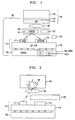
- Fig. 1 there is shown, in accordance with the present invention, an illustrative diagram of our ordnance fuse apparatus 100, which together with explosive charge 142 are part of an ordnance to be fired and detonated.
- the ordnance fuse apparatus 100 is shown to include five main components including a laser and detector unit 110, an optical switch or shutter 120, a microlens 130, an explosive charge 142 and a "programmable" electronic control chip 150.
- the laser/detector unit 110 includes laser 111 and detector 114 mounted on an Indium phosphide (InP) chip 115, which connects to controller chip 150.
- the laser/detector unit 110 may include built-in self-test circuitry to test the operation of laser 111 and pre- and post-firing position of optical switch 120.
- InP Indium phosphide
- the optical switch 120 is implemented using a MEMS shutter 121 (including an actuator which is used to move the MEMS shutter 121 upon firing of the ordnance.) and an accelerometer (g-switch) 122.
- the g-switch 122 or a spin detector can be used to detect that the ordnance has been fired.
- MEMS g-switches are described in U. S. Patents Nos. 6,167,809 and 6,321,654 .
- the MEMS g-switch 122 signals the controller chip 150 to move the shutter into the firing position.
- the MEMS shutter 121 may be implemented as described in the concurrently filed patent application of D. S. Greywall entitled “MICROMECHANICAL LATCHING SWITCH,” Serial No. 10/766,451 . It should be noted that the optical switching performed by MEMS shutter 121 may also occur by tilting a reflective element to redirect laser light to the explosive charge unit 140 rather than by moving the shutter to unblock the light (letting light pass) to explosive charge unit 140.
- MEMS optical switch which may be utilized is a MEMS mirror as described in the article entitled " Monolithic MEMS optical switch with amplified out-of-plane angular motion", written by "Lopez, D.; Simon, M.E.; Pardo, F.; Aksyuk, V.; Klemens, F.; Cirelli, R.; Neilson, D.T.; Shea, H.; Sorsch, T.; Ferry, E.; Nalamasu, O.; Gammel, P.L”, published in "Optical MEMs, 2002. Conference Digest. 2002 IEEE/LEOS International Conference on , 20-23 Aug. 2002, Page(s): 165 -166" on "2002 Aug. 23 ".
- electronic control chip 150 would receive a signal from an accelerometer (g-switch) 122 and generate a signal to the MEMS blocking mirror which would redirect the laser light from the detector 114 to the explosive charge unit 140.
- g-switch accelerometer
- the optical switch 120 need not have an accelerometer 122 incorporated therein.
- the accelerometer 122 could either not be needed or may be located on a chip separate from the optical switch 120 and/or fuse apparatus 100.
- the electronic control chip 150 uses timing or similar data loaded into the fuse from a fire control unit to determine the desired time and/or location when the fuse is to detonate the ordnance. Using this data, electronic control chip 150 may either initiate a timer or other control programs to control the turning-on/power level of the laser 111 and moving the shutter 121 to initiate detonation of explosive charge unit 140.
- fuse apparatus 100 does not include an accelerometer 120 it is less safe, since accelerometer 122 provides a redundant safeguard, providing a positive indication of the ordnance being fired. Redundancy is provided since the mechanical activation of accelerometer 122 would be used to detect the ordnance firing and signal the electronic control chip 150 to increase the power level of the laser 111 to ignite explosive charge unit 140.
- a spin-sensor 123 could be incorporated with the fuse apparatus 100 to detect the spin that occurs when the ordnance is fired and signal the electronic control chip 150. This spin-sensor 123 would provide additional safety that the ordnance would not explode for any g-force, e.g., dropping, not caused by ordnance being fired.
- the explosive charge unit 140 may include an explosive charge 142 alone or in combination with a Reactive Nano Technologies (RNT) foil 141 (as a primer charge).
- RNT foil 142 is a highly energetic nano-metal material that is easily ignited by a focused laser. It should be noted that other types of pyrotechnic or explosive device that can be ignited by a focused laser could be substituted for the RNT foil 141.
- the ordnance includes an explosive charge 142, but not a RNT foil 141, the laser 111 power must be made sufficient to directly ignite the explosive charge 142.
- the explosive charge unit 140 includes a RNT foil 141, the laser 111 ignites RNT foil 141, which then ignites the explosive charge 142.
- a RNT foil 141 is used, it is implemented as part of the ordnance fuse apparatus 100, while the explosive charge 142 is not included as part of the ordnance fuse apparatus 100.
- Figure 1 shows ordnance fuse apparatus 100 during it pre-fire state.
- controller 150 receives timing or similar data, via Data input leads 117. This data is used to program the controller 150 to static test the ordnance fuse apparatus 100 and to control the detonation of the explosive charge 140 of the ordnance at the desired time and/or location.
- controller 150 may be powered by an included battery 151 that is turned-on by a signal on one of the Data leads or by a capacitor 152 that is charged via one of the Data leads, or by a separate power lead, during the pre-fire state.
- step 301 the ordnance (containing our fuse apparatus 100 of Fig. 1 ) is loaded in the gun barrel and coupled to the Data leads from the gun fire-control unit (not shown).
- step 302 the capacitor(s) 152 is charged or the internal battery is "turned-on" to provide power to operate the fuse apparatus 100.
- Controller 150 then receives fire-control programs and/or data via Data leads 117, in a well-known manner from the fire control unit of the gun.
- controller 150 performs self-testing to check that the MEMS shutter 120 position is in the closed (blocking) position, preventing laser light from reaching the explosive charge unit 140.
- the MEMS shutter 121 position may be determined using a mechanical position sensor. If the MEMS shutter position is not correct, the procedure is aborted, in step 306, and an Abort signal is sent back to the fire control unit to prevent the ordnance from being fired. If the position is correct, then in step 304 controller 150 checks the operation of the laser 11 and detector 114, by detecting low-power pulses ( ⁇ 1mW) from the laser 111 which are reflected by the shutter 120 onto the detector 114.
- ⁇ 1mW low-power pulses
- step 305 if it is determined that the MEMS shutter position is not safe, then in step 306 an Abort signal is sent back to the fire control unit to prevent the ordnance from being fired.
- the low power laser pulses are of such a low power that they cannot ignite the explosive even if the shutter somehow were open.
- step 307 If the position is safe, the self-test passed and the fire control unit is notified, in step 307, that the ordnance can be fired. This information is transmitted back to the fire control unit during a talkback phase of the pre-firing state, to confirm data decoding and correct ordnance fuse apparatus 100 operation.
- the steps 301 -307 complete the pre-firing state.
- step 308 the ordnance is fired and the rapid ordnance acceleration causes accelerometer (g-switch) 122 to move MEMS shutter 121 to the partially armed position in step 309.
- a separate sensor e.g., a timer or shock sensor
- the fuse may be programmed by controller 150 to detonate after a certain time from firing or there may be some other means to determine when the fuse should go off, for example another shock sensor to detect when it has hit a wall or tank, or a proximity sensor or an altimeter, etc.
- step 311 the MEMS shutter enters a fully armed state.
- the MEMS shutter position moved again electrically or thermally in response to a shutter control signal from controller 150.
- the shutter control signal is applied after a predetermined programmed time has elapsed or in response to the shock sensor signal.
- the ordnance is then ready to detonate and, in step 312, the laser 111 power is ramped up to its maximum value.
- the MEMS shutter 121 either unblocks or redirects the laser 1 1 1 light enabling it to impact and ignite the RNT foil 141.
- the ignited RNT foil 141 rapidly heats up to over 1000°C, igniting the primary explosive (or pyrotechnic) charge 142 (201 of Fig. 2 ).
- the explosive charge unit 140 docs not include RNT foil 141 and laser 111 directly ignites the primary explosive charge 142.
- the ordnance fuse apparatus 100 is implemented as an integrated system that includes a specially built chip (110, 130) that includes laser111, with an integrated detector 114, and a micromachined lens 130.
- this laser/detector/lens chip (110 and 130) may be implemented as an Indium Phosphide (InP) chip.
- the laser/detector/lens chip and MEMS unit 120 (including an optical shutter/switch and an accelerometer g-switch) may be bonded to a conventional "micro" core unit.
- An integrated thin film of energetic, nano-metal foil 141 is attached to the micro-core unit. The sensitivity of the RNT foil 141 is selected to safely and reliably operate in the hostile environment of the ordnance.
- the RNT foil (or pyrotechnic or explosive charge) 141 may be encapsulated in a glass for passivation and protection.
- the glass could be a spin-on or sol-gel like glass.
- the glass envelope protects the nano metal from heat or chemical attack. However, the glass is easily penetrated by a laser pulse; the heat of that laser pulse is contained within the "oven" like chamber created by the glass encapsulation and detonation can occur rapidly and reliably. Thus the glass coating both protects the foil from oxidation or contamination, and enhances its explosive performance. So the heat from a focused laser pulse (which readily penetrates the glass envelope, if present) starts a reaction in the RNT foil 141 that quickly heats up to over 1000°C, thus detonating the explosive charge 142 rapidly and reliably.
- our ordnance fuse apparatus 100 may be implemented to layer the RNT foil 141 with a thin layer or coating 143 of an explosive compound, such as silver azide or lead azide, that will be ignited by the heat of the ignited RNT foil 141 and generate the shock wave needed to initiate an explosion in the primary explosive charge 142.
- the thin explosive layer 143 could be for example sputtered or painted onto the RNT foil 141. This approach combines the laser ignition of the RNT foil 141 with the shock wave generation utilized to initiate a conventional explosive.
- Our ordnance fuse apparatus 100 incorporates a number of unique safety features including:
- our ordnance fuse apparatus 100 includes only a laser 111, a MEMS shutter 121, RNT foil 141, and controller 150.
- controller 150 cannot determine whether laser 111 is operating at all or at what power level and cannot electrically determine that MEMS shutter 121 is in the correct position.
- laser III must have sufficient unfocused power to ignite the RNT foil 142.
Landscapes
- Engineering & Computer Science (AREA)
- General Engineering & Computer Science (AREA)
- Physics & Mathematics (AREA)
- Optics & Photonics (AREA)
- Laser Beam Processing (AREA)
- Switches Operated By Changes In Physical Conditions (AREA)
- Radiation-Therapy Devices (AREA)
- Laser Surgery Devices (AREA)
- Lasers (AREA)
Applications Claiming Priority (2)
| Application Number | Priority Date | Filing Date | Title |
|---|---|---|---|
| US766449 | 2004-01-27 | ||
| US10/766,449 US7216589B2 (en) | 2004-01-27 | 2004-01-27 | Fuse for projected ordnance |
Publications (2)
| Publication Number | Publication Date |
|---|---|
| EP1559986A1 EP1559986A1 (en) | 2005-08-03 |
| EP1559986B1 true EP1559986B1 (en) | 2008-05-14 |
Family
ID=34654333
Family Applications (1)
| Application Number | Title | Priority Date | Filing Date |
|---|---|---|---|
| EP05250062A Not-in-force EP1559986B1 (en) | 2004-01-27 | 2005-01-07 | Fuse for projected ordnance |
Country Status (5)
| Country | Link |
|---|---|
| US (1) | US7216589B2 (ko) |
| EP (1) | EP1559986B1 (ko) |
| JP (1) | JP4652831B2 (ko) |
| KR (1) | KR101193822B1 (ko) |
| DE (1) | DE602005006632D1 (ko) |
Families Citing this family (14)
| Publication number | Priority date | Publication date | Assignee | Title |
|---|---|---|---|---|
| US8113118B2 (en) * | 2004-11-22 | 2012-02-14 | Alliant Techsystems Inc. | Spin sensor for low spin munitions |
| FR2892809B1 (fr) | 2005-10-27 | 2010-07-30 | Giat Ind Sa | Dispositif de securite pyrotechnique a dimensions reduites |
| FR2892810B1 (fr) | 2005-10-27 | 2010-05-14 | Giat Ind Sa | Dispositif de securite pyrotechnique a ecran micro usine |
| CN100453960C (zh) * | 2006-06-06 | 2009-01-21 | 西安理工大学 | 光控纳秒电点火装置 |
| JP2009008325A (ja) * | 2007-06-28 | 2009-01-15 | Ihi Aerospace Co Ltd | 爆発物の処理方法 |
| US8213151B2 (en) * | 2008-12-31 | 2012-07-03 | Pacific Scientific Energetic Materials Company (California), LLC | Methods and systems for defining addresses for pyrotechnic devices networked in an electronic ordnance system |
| US8750340B1 (en) * | 2010-07-28 | 2014-06-10 | Intuitive Research And Technology Corporation | Laser ordnance safe-arm distributor |
| FR2971049B1 (fr) | 2011-01-31 | 2013-01-18 | Nexter Munitions | Dispositif de temporisation d'un mouvement d'une masselotte micro-usinee et dispositif de securite et d'armement comprenant un tel dispositif de temporisation |
| FR2971048B1 (fr) | 2011-01-31 | 2013-01-11 | Nexter Munitions | Dispositif de securite et d'armement a verrou cassable |
| JP6736431B2 (ja) * | 2016-09-06 | 2020-08-05 | 株式会社Ihiエアロスペース | レーザ着火用セーフアーム装置 |
| US9810515B1 (en) | 2017-02-03 | 2017-11-07 | Pacific Scientific Energetic Materials Company (California) LLC | Multi-level networked ordnance system |
| TR202008782A2 (tr) * | 2020-06-08 | 2021-12-21 | Roketsan Roket Sanayi Ve Ticaret Anonim Sirketi | Düşük enerji̇li̇ elektroni̇k emni̇yet kurma ve ateşleme si̇stemi̇ |
| CN111610749B (zh) * | 2020-07-01 | 2021-07-02 | 中国人民解放军陆军装甲兵学院 | 多炸点引爆控制装置 |
| CN112880492B (zh) * | 2021-02-02 | 2022-08-05 | 湖北三江航天红林探控有限公司 | 一种炮射后坐过载启动的开关及其工作方法 |
Family Cites Families (10)
| Publication number | Priority date | Publication date | Assignee | Title |
|---|---|---|---|---|
| US3812783A (en) * | 1972-08-03 | 1974-05-28 | Nasa | Optically detonated explosive device |
| US4694752A (en) * | 1986-10-02 | 1987-09-22 | Motorola, Inc. | Fuze actuating method having an adaptive time delay |
| FR2646901B1 (fr) * | 1989-05-12 | 1994-04-29 | Aerospatiale | Dispositif d'amorcage photopyrotechnique comportant une microlentille sertie par un materiau a memoire de forme et chaine pyrotechnique utilisant ce dispositif |
| US5204490A (en) * | 1991-06-21 | 1993-04-20 | Mcdonnell Douglas Corporation | Laser diode apparatus for initiation of explosive devices |
| US5229542A (en) * | 1992-03-27 | 1993-07-20 | The United States Of America As Represented By The United States Department Of Energy | Selectable fragmentation warhead |
| US5502300A (en) * | 1993-03-31 | 1996-03-26 | Santa Barbara Research Center | Compound optically tipped detectors |
| US5684631A (en) | 1996-05-13 | 1997-11-04 | Lucent Technologies Inc. | Optical modulator/switch including reflective zone plate and related method of use |
| FR2760266B1 (fr) | 1997-02-28 | 1999-05-21 | Tda Armements Sas | Dispositif de mise a feu multipoints |
| US6167809B1 (en) * | 1998-11-05 | 2001-01-02 | The United States Of America As Represented By The Secretary Of The Army | Ultra-miniature, monolithic, mechanical safety-and-arming (S&A) device for projected munitions |
| US6321654B1 (en) * | 2000-02-22 | 2001-11-27 | The United States Of America As Represented By The Secretary Of The Army | Microelectromechanical systems (MEMS) -type devices having latch release and output mechanisms |
-
2004
- 2004-01-27 US US10/766,449 patent/US7216589B2/en not_active Expired - Fee Related
-
2005
- 2005-01-07 DE DE602005006632T patent/DE602005006632D1/de active Active
- 2005-01-07 EP EP05250062A patent/EP1559986B1/en not_active Not-in-force
- 2005-01-21 KR KR1020050005819A patent/KR101193822B1/ko not_active IP Right Cessation
- 2005-01-27 JP JP2005019466A patent/JP4652831B2/ja not_active Expired - Fee Related
Also Published As
| Publication number | Publication date |
|---|---|
| EP1559986A1 (en) | 2005-08-03 |
| JP2005214619A (ja) | 2005-08-11 |
| KR20050077265A (ko) | 2005-08-01 |
| DE602005006632D1 (de) | 2008-06-26 |
| US7216589B2 (en) | 2007-05-15 |
| US20050183605A1 (en) | 2005-08-25 |
| KR101193822B1 (ko) | 2012-10-23 |
| JP4652831B2 (ja) | 2011-03-16 |
Similar Documents
| Publication | Publication Date | Title |
|---|---|---|
| EP1559986B1 (en) | Fuse for projected ordnance | |
| US6923122B2 (en) | Energetic material initiation device utilizing exploding foil initiated ignition system with secondary explosive material | |
| US5485788A (en) | Combination explosive primer and electro-explosive device | |
| US6173650B1 (en) | MEMS emergetic actuator with integrated safety and arming system for a slapper/EFI detonator | |
| US5271327A (en) | Elecro-mechanical base element fuze | |
| EP0686825B1 (en) | Shock tolerant fuze | |
| US8887640B1 (en) | Electro-mechanical fuze for hand grenades | |
| EP0850396A1 (en) | Electro-mechanical safety and arming device | |
| JPS63254399A (ja) | 安全および安全解放機構を具える弾丸の圧電信管 | |
| US5872324A (en) | Trimode fuze | |
| US9562755B2 (en) | Safe and arm mechanisms and methods for explosive devices | |
| US4372211A (en) | Thermoelectric power supply for warheads | |
| WO1999030107A1 (en) | A hermetically sealed laser actuator/detonator and method of manufacturing the same | |
| US4603635A (en) | Dual safing for base element fuze | |
| US4770096A (en) | Safing and arming mechanism | |
| US7055437B1 (en) | Micro-scale firetrain for ultra-miniature electro-mechanical safety and arming device | |
| US5147975A (en) | Remotely settable, multi-output, electronic time fuze and method of operation | |
| US4047484A (en) | Fuze with bimetallic spring delay module | |
| US4378740A (en) | Munition fuse system having out-of-line safety device | |
| RU2456537C2 (ru) | Взрыватель для снарядов реактивных систем залпового огня | |
| US3641938A (en) | Percussion or vibration fuse for explosive charge | |
| US2934019A (en) | Fuze assembly | |
| US7069861B1 (en) | Micro-scale firetrain for ultra-miniature electro-mechanical safety and arming device | |
| US5101470A (en) | Fiber optic light sensor for safing and arming a fuze | |
| US2900906A (en) | Self-destruction device |
Legal Events
| Date | Code | Title | Description |
|---|---|---|---|
| PUAI | Public reference made under article 153(3) epc to a published international application that has entered the european phase |
Free format text: ORIGINAL CODE: 0009012 |
|
| 17P | Request for examination filed |
Effective date: 20050127 |
|
| AK | Designated contracting states |
Kind code of ref document: A1 Designated state(s): AT BE BG CH CY CZ DE DK EE ES FI FR GB GR HU IE IS IT LI LT LU MC NL PL PT RO SE SI SK TR |
|
| AX | Request for extension of the european patent |
Extension state: AL BA HR LV MK YU |
|
| AKX | Designation fees paid |
Designated state(s): DE FR GB |
|
| 17Q | First examination report despatched |
Effective date: 20060130 |
|
| GRAP | Despatch of communication of intention to grant a patent |
Free format text: ORIGINAL CODE: EPIDOSNIGR1 |
|
| GRAS | Grant fee paid |
Free format text: ORIGINAL CODE: EPIDOSNIGR3 |
|
| GRAA | (expected) grant |
Free format text: ORIGINAL CODE: 0009210 |
|
| AK | Designated contracting states |
Kind code of ref document: B1 Designated state(s): DE FR GB |
|
| REG | Reference to a national code |
Ref country code: GB Ref legal event code: FG4D |
|
| REF | Corresponds to: |
Ref document number: 602005006632 Country of ref document: DE Date of ref document: 20080626 Kind code of ref document: P |
|
| PLBE | No opposition filed within time limit |
Free format text: ORIGINAL CODE: 0009261 |
|
| STAA | Information on the status of an ep patent application or granted ep patent |
Free format text: STATUS: NO OPPOSITION FILED WITHIN TIME LIMIT |
|
| 26N | No opposition filed |
Effective date: 20090217 |
|
| PGFP | Annual fee paid to national office [announced via postgrant information from national office to epo] |
Ref country code: FR Payment date: 20130213 Year of fee payment: 9 Ref country code: GB Payment date: 20130122 Year of fee payment: 9 Ref country code: DE Payment date: 20130122 Year of fee payment: 9 |
|
| REG | Reference to a national code |
Ref country code: GB Ref legal event code: 732E Free format text: REGISTERED BETWEEN 20131107 AND 20131113 |
|
| REG | Reference to a national code |
Ref country code: FR Ref legal event code: CD Owner name: ALCATEL-LUCENT USA INC. Effective date: 20131122 |
|
| REG | Reference to a national code |
Ref country code: FR Ref legal event code: GC Effective date: 20140410 |
|
| REG | Reference to a national code |
Ref country code: DE Ref legal event code: R119 Ref document number: 602005006632 Country of ref document: DE |
|
| GBPC | Gb: european patent ceased through non-payment of renewal fee |
Effective date: 20140107 |
|
| REG | Reference to a national code |
Ref country code: DE Ref legal event code: R119 Ref document number: 602005006632 Country of ref document: DE Effective date: 20140801 |
|
| PG25 | Lapsed in a contracting state [announced via postgrant information from national office to epo] |
Ref country code: DE Free format text: LAPSE BECAUSE OF NON-PAYMENT OF DUE FEES Effective date: 20140801 |
|
| REG | Reference to a national code |
Ref country code: FR Ref legal event code: ST Effective date: 20140930 |
|
| REG | Reference to a national code |
Ref country code: FR Ref legal event code: RG Effective date: 20141015 |
|
| PG25 | Lapsed in a contracting state [announced via postgrant information from national office to epo] |
Ref country code: FR Free format text: LAPSE BECAUSE OF NON-PAYMENT OF DUE FEES Effective date: 20140131 Ref country code: GB Free format text: LAPSE BECAUSE OF NON-PAYMENT OF DUE FEES Effective date: 20140107 |