EP1559635B1 - Steering arrangement for steerable front wheels - Google Patents
Steering arrangement for steerable front wheels Download PDFInfo
- Publication number
- EP1559635B1 EP1559635B1 EP05009650A EP05009650A EP1559635B1 EP 1559635 B1 EP1559635 B1 EP 1559635B1 EP 05009650 A EP05009650 A EP 05009650A EP 05009650 A EP05009650 A EP 05009650A EP 1559635 B1 EP1559635 B1 EP 1559635B1
- Authority
- EP
- European Patent Office
- Prior art keywords
- steering
- lever
- arm
- front wheels
- tie rod
- Prior art date
- Legal status (The legal status is an assumption and is not a legal conclusion. Google has not performed a legal analysis and makes no representation as to the accuracy of the status listed.)
- Expired - Lifetime
Links
- 239000000725 suspension Substances 0.000 description 2
Images

Classifications
-
- B—PERFORMING OPERATIONS; TRANSPORTING
- B62—LAND VEHICLES FOR TRAVELLING OTHERWISE THAN ON RAILS
- B62D—MOTOR VEHICLES; TRAILERS
- B62D7/00—Steering linkage; Stub axles or their mountings
- B62D7/06—Steering linkage; Stub axles or their mountings for individually-pivoted wheels, e.g. on king-pins
- B62D7/08—Steering linkage; Stub axles or their mountings for individually-pivoted wheels, e.g. on king-pins the pivotal axes being situated in a single plane transverse to the longitudinal centre line of the vehicle
-
- B—PERFORMING OPERATIONS; TRANSPORTING
- B62—LAND VEHICLES FOR TRAVELLING OTHERWISE THAN ON RAILS
- B62D—MOTOR VEHICLES; TRAILERS
- B62D7/00—Steering linkage; Stub axles or their mountings
- B62D7/06—Steering linkage; Stub axles or their mountings for individually-pivoted wheels, e.g. on king-pins
- B62D7/08—Steering linkage; Stub axles or their mountings for individually-pivoted wheels, e.g. on king-pins the pivotal axes being situated in a single plane transverse to the longitudinal centre line of the vehicle
- B62D7/10—Steering linkage; Stub axles or their mountings for individually-pivoted wheels, e.g. on king-pins the pivotal axes being situated in a single plane transverse to the longitudinal centre line of the vehicle with single-output steering gear
-
- B—PERFORMING OPERATIONS; TRANSPORTING
- B62—LAND VEHICLES FOR TRAVELLING OTHERWISE THAN ON RAILS
- B62D—MOTOR VEHICLES; TRAILERS
- B62D7/00—Steering linkage; Stub axles or their mountings
- B62D7/16—Arrangement of linkage connections
-
- B—PERFORMING OPERATIONS; TRANSPORTING
- B62—LAND VEHICLES FOR TRAVELLING OTHERWISE THAN ON RAILS
- B62D—MOTOR VEHICLES; TRAILERS
- B62D7/00—Steering linkage; Stub axles or their mountings
- B62D7/20—Links, e.g. track rods
-
- B—PERFORMING OPERATIONS; TRANSPORTING
- B60—VEHICLES IN GENERAL
- B60G—VEHICLE SUSPENSION ARRANGEMENTS
- B60G2200/00—Indexing codes relating to suspension types
- B60G2200/10—Independent suspensions
- B60G2200/14—Independent suspensions with lateral arms
- B60G2200/144—Independent suspensions with lateral arms with two lateral arms forming a parallelogram
-
- B—PERFORMING OPERATIONS; TRANSPORTING
- B60—VEHICLES IN GENERAL
- B60G—VEHICLE SUSPENSION ARRANGEMENTS
- B60G2200/00—Indexing codes relating to suspension types
- B60G2200/40—Indexing codes relating to the wheels in the suspensions
- B60G2200/44—Indexing codes relating to the wheels in the suspensions steerable
-
- B—PERFORMING OPERATIONS; TRANSPORTING
- B60—VEHICLES IN GENERAL
- B60G—VEHICLE SUSPENSION ARRANGEMENTS
- B60G2202/00—Indexing codes relating to the type of spring, damper or actuator
- B60G2202/10—Type of spring
- B60G2202/15—Fluid spring
- B60G2202/152—Pneumatic spring
-
- B—PERFORMING OPERATIONS; TRANSPORTING
- B60—VEHICLES IN GENERAL
- B60G—VEHICLE SUSPENSION ARRANGEMENTS
- B60G2204/00—Indexing codes related to suspensions per se or to auxiliary parts
- B60G2204/10—Mounting of suspension elements
- B60G2204/14—Mounting of suspension arms
- B60G2204/143—Mounting of suspension arms on the vehicle body or chassis
-
- B—PERFORMING OPERATIONS; TRANSPORTING
- B60—VEHICLES IN GENERAL
- B60G—VEHICLE SUSPENSION ARRANGEMENTS
- B60G2204/00—Indexing codes related to suspensions per se or to auxiliary parts
- B60G2204/10—Mounting of suspension elements
- B60G2204/14—Mounting of suspension arms
- B60G2204/148—Mounting of suspension arms on the unsprung part of the vehicle, e.g. wheel knuckle or rigid axle
-
- B—PERFORMING OPERATIONS; TRANSPORTING
- B60—VEHICLES IN GENERAL
- B60G—VEHICLE SUSPENSION ARRANGEMENTS
- B60G2204/00—Indexing codes related to suspensions per se or to auxiliary parts
- B60G2204/40—Auxiliary suspension parts; Adjustment of suspensions
- B60G2204/416—Ball or spherical joints
-
- B—PERFORMING OPERATIONS; TRANSPORTING
- B60—VEHICLES IN GENERAL
- B60G—VEHICLE SUSPENSION ARRANGEMENTS
- B60G2206/00—Indexing codes related to the manufacturing of suspensions: constructional features, the materials used, procedures or tools
- B60G2206/01—Constructional features of suspension elements, e.g. arms, dampers, springs
- B60G2206/10—Constructional features of arms
- B60G2206/121—Constructional features of arms the arm having an H or X-shape
-
- B—PERFORMING OPERATIONS; TRANSPORTING
- B60—VEHICLES IN GENERAL
- B60G—VEHICLE SUSPENSION ARRANGEMENTS
- B60G2300/00—Indexing codes relating to the type of vehicle
- B60G2300/14—Buses
-
- B—PERFORMING OPERATIONS; TRANSPORTING
- B60—VEHICLES IN GENERAL
- B60G—VEHICLE SUSPENSION ARRANGEMENTS
- B60G2300/00—Indexing codes relating to the type of vehicle
- B60G2300/38—Low or lowerable bed vehicles
Definitions
- the invention relates to a steering device for steerable front wheels according to the closer defined in the preamble of claim 1.
- Such steering devices are preferably in heavy commercial vehicles, such as.
- trucks or buses used, due to the high steering forces no rack and pinion steering, sondem screw gear are used.
- the push rod acts directly on the rear steering arm.
- Coaches use an independent suspension, which require a long overhang due to the longitudinal push rod.
- EP 0 806 310 A2 and DE 196 19 189 A1 disclose a steering device for a commercial vehicle, in which a lever arm, which is driven by a helical gear, acts on a push rod which has an intermediate steering lever, a tie rod and a steering lever the stub axle of the front wheel acts.
- the push rod is arranged in the vehicle direction, whereby when using this steering device, the commercial vehicle needs a long front overhang.
- the present invention has for its object to provide a steering device for steerable front wheels, which can be used in a commercial vehicle with an independent suspension and short front overhang.
- the object is achieved with a, also the characterizing features of the main claim, generic steering device for steerable front wheels.
- the screw gear is arranged in front of the axis of rotation of the front wheels so that the push rod is arranged substantially transverse to the direction of travel.
- the helical gear of the steering device acts via a lever arm on the push rod, which acts on the steering intermediate lever, which is arranged further away from the helical gear.
- Each front wheel is connected via a steering lever and a tie rod with a steering intermediate lever and the intermediate steering levers are connected to each other via a tie rod.
- the worm gear is arranged so that the lever arm of the worm gear substantially transverse to the direction of travel is rotatable.
- the worm gear and the push rod are arranged in front of the axis of rotation of the front wheels.
- the wishbones and the tie rods are arranged one behind the other in the vehicle direction.
- the steering device By the push rod arranged transversely to the direction of travel and the lever arm of the screw gear is substantially transverse to the direction of rotation, the steering device can be used for commercial vehicles with a short front overhang.
- the wishbones and the tie rods do not cross, there is sufficient clearance between the front wheels.
- the push rod is arranged on the one hand on the lever arm of the screw gear and on the other hand on the steering intermediate lever, which is arranged further away from the helical gear, the push rod can be made with sufficient length.
- the steering lever is connected to a steering knuckle, which receives the wheel forces.
- the steering knuckle is preferably connected to the vehicle chassis via upper and lower transverse links.
- the bumper directly in front of the front wheels.
- the lever arm 1 of a screw gear 2 is arranged to be rotatable substantially transversely to the direction of travel.
- the push rod 3 is connected on the one hand with the lever arm 1 and on the other hand with a steering intermediate lever 4.
- the intermediate steering lever 4 is stationary, but rotatably connected to the vehicle chassis 6.
- the tie rod 7 connects the steering intermediate lever 4 with the intermediate steering lever 5.
- the tie rod 8 is connected to the steering intermediate lever 4 and the steering lever 9.
- the steering lever 9 is connected to a steering knuckle, not shown.
- the intermediate steering lever 5 is connected on one side to the vehicle chassis 6 and to the tie rod 7 and on the other hand to the tie rod 10.
- the tie rod 10 is connected via the steering lever 11 with a steering knuckle, not shown.
- the steering device can be used for commercial vehicles with a short front overhang.
- the tie rods 8 and 10 and the steering levers 9 and 11 do not intersect with the lower arms 12, sufficient clearance to the engine tunnel is available.
- the lever arm 1 of the screw gear 2 is connected to the push rod 3.
- the push rod 3 is connected via the intermediate steering lever 4 and the tie rod 8 to the steering lever 9.
- the steering lever 9 and the tie rod 8 are arranged in the direction of travel in front of the control arm 12, so that, since the wishbone 12 and the tie rod 8 do not intersect, sufficient clearance between the front wheels is present.
- the lever arm 1 of a screw gear 2 is arranged to be rotatable substantially transversely to the direction of travel.
- the push rod 3 is connected on the one hand with the lever arm 1 and on the other hand with a steering intermediate lever 4.
- the intermediate steering lever 4 is stationary, but rotatably connected to the vehicle chassis 6.
- the steering intermediate lever 4 has a pivot point 13, which is arranged centrally and about which the intermediate steering lever 4 can rotate.
- the tie rod 8 connects the steering intermediate lever 4 with the steering lever 9.
- the tie rod 10 connects the steering intermediate lever 4 with the steering lever 11.
- the steering lever 10 and the steering lever 11 are connected to steering knuckles, not shown.
Landscapes
- Engineering & Computer Science (AREA)
- Chemical & Material Sciences (AREA)
- Combustion & Propulsion (AREA)
- Transportation (AREA)
- Mechanical Engineering (AREA)
- Steering-Linkage Mechanisms And Four-Wheel Steering (AREA)
Description
Die Erfindung betrifft eine Lenkvorrichtung für lenkbare Vorderräder nach der im Oberbegriff von Anspruch 1 näher definierten Art.The invention relates to a steering device for steerable front wheels according to the closer defined in the preamble of
Derartige Lenkvorrichtungen werden vorzugsweise in schweren Nutzkraftfahrzeugen, wie z. B. Lastkraftwagen oder Omnibussen, eingesetzt, wobei aufgrund der hohen Lenkkräfte keine Zahnstangenlenkungen, sondem Schraubengetriebe, verwendet werden. Für Lastkraftwagen mit kurzem vorderen Überhang werden vorzugsweise Starrachsen verwendet, wobei die Schubstange direkt auf den hinteren Lenkhebel wirkt. Reisebusse verwenden eine Einzelradaufhängung, welche aufgrund der längs angeordneten Schubstange einen langen Überhang benötigen.Such steering devices are preferably in heavy commercial vehicles, such as. As trucks or buses, used, due to the high steering forces no rack and pinion steering, sondem screw gear are used. For trucks with short front overhang preferably rigid axles are used, the push rod acts directly on the rear steering arm. Coaches use an independent suspension, which require a long overhang due to the longitudinal push rod.
In der EP 0 806 310 A2 und der DE 196 19 189 A1 ist eine Lenkvorrichtung für ein Nutzkraftfahrzeug offenbart, bei welchem ein Hebelarm, welcher von einem Schraubengetriebe angetrieben wird, auf eine Schubstange wirkt, welche über einen Lenkzwischenhebel, eine Spurstange und einen Lenkhebel auf den Achsschenkel des Vorderrades wirkt. Die Schubstange ist in Fahrzeugrichtung angeordnet, wodurch bei Verwendung dieser Lenkvorrichtung das Nutzfahrzeug einen langen vorderen Überhang benötigt.EP 0 806 310 A2 and DE 196 19 189 A1 disclose a steering device for a commercial vehicle, in which a lever arm, which is driven by a helical gear, acts on a push rod which has an intermediate steering lever, a tie rod and a steering lever the stub axle of the front wheel acts. The push rod is arranged in the vehicle direction, whereby when using this steering device, the commercial vehicle needs a long front overhang.
In der EP 0 278 095 B1 ist eine Lenkvorrichtung für lenkbare Hinterräder beschrieben, bei welcher die Schubstange über Lenkzwischenhebel auf einen unteren Querlenker des Hinterrades wirkt und somit einen Lenkeinschlag der Hinterräder ermöglicht. Indem der Lenkzwischenhebel auf einen Querlenker wirkt, können nur geringe Lenkeinschläge realisiert werden. Die verwendete Zahnstangenlenkung, welche auf die Schubstange wirkt, ist für die Verwendung im Nutzfahrzeug nicht geeignet, da die dort auftretenden Lenkkräfte nicht bewältigt werden können.In EP 0 278 095 B1 a steering device for steerable rear wheels is described, in which the push rod acts via the intermediate steering lever on a lower arm of the rear wheel and thus allows a steering angle of the rear wheels. By the steering intermediate lever acts on a control arm, only small steering angles can be realized. The used rack and pinion steering which acts on the push rod is for use not suitable in commercial vehicles, since the steering forces occurring there can not be coped with.
Die Veröffentlichung von Reimpell, Jömsen, Fahrwerkstechnik/Jörnsen Reimpell. - Würzburg: Vogel (Vogel-Fachbuch: Technik: Kraftfahrzeugwesen) Seite 130, Bild 3.5/2 offenbart eine Lenkvorrichtung für lenkbare Vorderräder bei welchem ein Lenkgetriebe eine quer zur Fahrtrichtung vor einer Drehachse der Vorderräder angeordneten Schubstange verschiebt, welche mit einem Lenkhebel verbunden ist, welcher über eine Spurstange welche hinter der Drehachse der Vorderräder liegt, mit dem Lenkhebel des anderen Fahrzeugrades verbunden ist.The publication by Reimpell, Jömsen, Fahrwerkstechnik / Jörnsen Reimpell. - Würzburg: Vogel (Vogel-Fachbuch: Technik: Kraftfahrzeugwesen) page 130, Figure 3.5 / 2 discloses a steering device for steerable front wheels in which a steering gear shifts a transversely to the direction of travel in front of a rotational axis of the front wheels arranged push rod which is connected to a steering lever, which is connected via a tie rod which is behind the axis of rotation of the front wheels, with the steering lever of the other vehicle wheel.
Der vorliegenden Erfindung liegt die Aufgabe zugrunde, eine Lenkvorrichtung für lenkbare Vorderräder zu schaffen, welche in einem Nutzfahrzeug mit einer Einzelradaufhängung und kurzem vorderen Überhang verwendet werden kann.The present invention has for its object to provide a steering device for steerable front wheels, which can be used in a commercial vehicle with an independent suspension and short front overhang.
Die Aufgabe wird mit einer, auch die kennzeichnenden Merkmale des Hauptanspruchs aufweisenden, gattungsgemäßen Lenkvorrichtung für lenkbare Vorderräder gelöst.The object is achieved with a, also the characterizing features of the main claim, generic steering device for steerable front wheels.
Erfindungsgemäß ist das Schraubengetriebe vor der Drehachse der Vorderräder so angeordnet, daß die Schubstange im wesentlichen quer zur Fahrtrichtung angeordnet ist. Das Schraubengetriebe der Lenkvorrichtung wirkt über einen Hebelarm auf die Schubstange, welche auf den Lenkzwischenhebel wirkt, welcher dem Schraubengetriebe weiter entfernt angeordnet ist. Jedes Vorderrad ist über einen Lenkhebel und eine Spurstange mit einem Lenkzwischenhebel verbunden und die Lenkzwischenhebel sind über eine Spurstange miteinander verbunden. Das Schraubengetriebe ist so angeordnet, daß der Hebelarm des Schraubengetriebes im wesentlichen quer zur Fahrtrichtung drehbar ist. Das Schraubengetriebe sowie die Schubstange sind vor der Drehachse der Vorderräder angeordnet. Die Querlenker sowie die Spurstangen sind in Fahrzeugrichtung nacheinander angeordnet. Indem die Schubstange quer zur Fahrtrichtung angeordnet und der Hebelarm des Schraubengetriebes im wesentlichen quer zur Fahrtrichtung drehbar ist, kann die Lenkvorrichtung für Nutzfahrzeuge mit kurzem vorderen Überhang verwendet werden. Indem die Querlenker und die Spurstangen sich nicht kreuzen, ist ausreichend Freigang zwischen den Vorderrädern vorhanden. Indem die Schubstange einerseits am Hebelarm des Schraubengetriebes und andererseits an dem Lenkzwischenhebel angeordnet ist, welcher dem Schraubengetriebe weiter entfernt angeordnet ist, kann die Schubstange mit ausreichender Länge ausgeführt werden. Der Lenkhebel ist mit einem Achsschenkel verbunden, welcher die Radkräfte aufnimmt.According to the screw gear is arranged in front of the axis of rotation of the front wheels so that the push rod is arranged substantially transverse to the direction of travel. The helical gear of the steering device acts via a lever arm on the push rod, which acts on the steering intermediate lever, which is arranged further away from the helical gear. Each front wheel is connected via a steering lever and a tie rod with a steering intermediate lever and the intermediate steering levers are connected to each other via a tie rod. The worm gear is arranged so that the lever arm of the worm gear substantially transverse to the direction of travel is rotatable. The worm gear and the push rod are arranged in front of the axis of rotation of the front wheels. The wishbones and the tie rods are arranged one behind the other in the vehicle direction. By the push rod arranged transversely to the direction of travel and the lever arm of the screw gear is substantially transverse to the direction of rotation, the steering device can be used for commercial vehicles with a short front overhang. By the wishbones and the tie rods do not cross, there is sufficient clearance between the front wheels. By the push rod is arranged on the one hand on the lever arm of the screw gear and on the other hand on the steering intermediate lever, which is arranged further away from the helical gear, the push rod can be made with sufficient length. The steering lever is connected to a steering knuckle, which receives the wheel forces.
Der Achsschenkel ist vorzugsweise über obere und untere Querlenker mit dem Fahrzeugchassis verbunden. Somit ist es möglich, die Stoßstange direkt vor den Vorderrädern anzuordnen.The steering knuckle is preferably connected to the vehicle chassis via upper and lower transverse links. Thus, it is possible to arrange the bumper directly in front of the front wheels.
Weitere Merkmale sind der Figuren-Beschreibung zu entnehmen. Es zeigen:
- Fig. 1
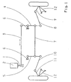
- eine schematische Darstellung einer Lenkvorrichtung für lenkbare Vorderräder eines Kraftfahrzeuges;
- Fig. 2
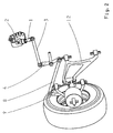
- eine räumliche Darstellung der Lenkvorrichtung eines Vorderrades und
- Fig. 3
- eine schematische Darstellung einer Lenkvorrichtung für lenkbare Vorderräder eines Kraftfahrzeuges.
- Fig. 1
- a schematic representation of a steering device for steerable front wheels of a motor vehicle;
- Fig. 2
- a spatial representation of the steering device of a front wheel and
- Fig. 3
- a schematic representation of a steering device for steerable front wheels of a motor vehicle.
Der Hebelarm 1 eines Schraubengetriebes 2 ist im wesentlichen quer zur Fahrtrichtung drehbar angeordnet. Die Schubstange 3 ist einerseits mit dem Hebelarm 1 und andererseits mit einem Lenkzwischenhebel 4 verbunden. Der Lenkzwischenhebel 4 ist ortsfest, jedoch drehbeweglich, mit dem Fahrzeugchassis 6 verbunden. Die Spurstange 7 verbindet den Lenkzwischenhebel 4 mit dem Lenkzwischenhebel 5. Die Spurstange 8 ist mit dem Lenkzwischenhebel 4 und dem Lenkhebel 9 verbunden. Der Lenkhebel 9 ist mit einem nicht dargestellten Achsschenkel verbunden. Der Lenkzwischenhebel 5 ist einerseits mit dem Fahrzeugchassis 6 und mit der Spurstange 7 und andererseits mit der Spurstange 10 verbunden. Die Spurstange 10 ist über den Lenkhebel 11 mit einem nicht dargestellten Achsschenkel verbunden. Indem die Schubstange 3 im wesentlichen quer zur Fahrtrichtung angeordnet und mit dem Hebelarm 1 und dem Lenkzwischenhebel 4 verbunden und der Hebelarm 1 im wesentlichen quer zur Fahrtrichtung drehbar ist, kann die Lenkvorrichtung für Nutzkraftfahrzeuge mit kurzem vorderen Überhang verwendet werden. Indem sich die Spurstangen 8 und 10 sowie die Lenkhebel 9 und 11 nicht mit den unteren Querlenkern 12 kreuzen, ist ausreichend Freigang zum Motortunnel vorhanden.The
Der Hebelarm 1 des Schraubengetriebes 2 ist mit der Schubstange 3 verbunden. Die Schubstange 3 ist über den Lenkzwischenhebel 4 und die Spurstange 8 mit dem Lenkhebel 9 verbunden. Der Lenkhebel 9 sowie die Spurstange 8 sind in Fahrtrichtung vor dem Querlenker 12 angeordnet, so daß, da sich der Querlenker 12 und die Spurstange 8 nicht kreuzen, ausreichend Freigang zwischen den Vorderrädern vorhanden ist.The
Der Hebelarm 1 eines Schraubengetriebes 2 ist im wesentlichen quer zur Fahrtrichtung drehbar angeordnet. Die Schubstange 3 ist einerseits mit dem Hebelarm 1 und andererseits mit einem Lenkzwischenhebel 4 verbunden. Der Lenkzwischenhebel 4 ist ortsfest, jedoch drehbeweglich, mit dem Fahrzeugchassis 6 verbunden. Der Lenkzwischenhebel 4 weist einen Drehpunkt 13 auf, welcher mittig angeordnet ist und um welchen sich der Lenkzwischenhebel 4 drehen kann. Die Spurstange 8 verbindet den Lenkzwischenhebel 4 mit dem Lenkhebel 9. Die Spurstange 10 verbindet den Lenkzwischenhebel 4 mit dem Lenkhebel 11. Der Lenkhebel 10 und der Lenkhebel 11 sind mit nicht dargestellten Achsschenkeln verbunden.The
- 11
- Hebelarmlever arm
- 22
- Schraubengetriebescrew gear
- 33
- Schubstangepushrod
- 44
- LenkzwischenhebelControl Arm
- 55
- LenkzwischenhebelControl Arm
- 66
- Fahrzeugchassisvehicle chassis
- 77
- Spurstangetie rod
- 88th
- Spurstangetie rod
- 99
- Lenkhebelsteering lever
- 1010
- Spurstangetie rod
- 1111
- Lenkhebelsteering lever
- 1212
- Querlenkerwishbone
- 1313
- Drehpunktpivot point
Claims (1)
- The invention relates to a steering system for the steerable front wheels of a motor vehicle with a helical gear (2), which - via a lever arm (1) - acts on a pushrod (3), which acts on a steering idler arm (4), which - via a steering tie rod (8) - acts on a pitman arm, which is linked to a steering knuckle of a front wheel, characterized in that each front wheel - via its steering knuckle and its pitman arm (9, 11) and its steering tie rod (8, 10) - is linked to a steering idler arm (4), with the steering idler arm (4) being directly linked to the pushrod (3) and rotatable around a central rotation point (13), and with the pushrod (3) being arranged essentially at right angles to the direction of travel in front of an axis of rotation of the front wheels and linked to the lever arm (1) of the helical gear (2) on the one hand and to the steering idler arm (4) on the other hand.
Applications Claiming Priority (3)
| Application Number | Priority Date | Filing Date | Title |
|---|---|---|---|
| DE2000161408 DE10061408A1 (en) | 2000-12-09 | 2000-12-09 | Steering device for steerable front wheels |
| DE10061408 | 2000-12-09 | ||
| EP20010128782 EP1213206B1 (en) | 2000-12-09 | 2001-12-04 | Steering arrangement for steerable front wheels |
Related Parent Applications (1)
| Application Number | Title | Priority Date | Filing Date |
|---|---|---|---|
| EP20010128782 Division EP1213206B1 (en) | 2000-12-09 | 2001-12-04 | Steering arrangement for steerable front wheels |
Publications (2)
| Publication Number | Publication Date |
|---|---|
| EP1559635A1 EP1559635A1 (en) | 2005-08-03 |
| EP1559635B1 true EP1559635B1 (en) | 2006-07-12 |
Family
ID=7666506
Family Applications (2)
| Application Number | Title | Priority Date | Filing Date |
|---|---|---|---|
| EP20010128782 Expired - Lifetime EP1213206B1 (en) | 2000-12-09 | 2001-12-04 | Steering arrangement for steerable front wheels |
| EP05009650A Expired - Lifetime EP1559635B1 (en) | 2000-12-09 | 2001-12-04 | Steering arrangement for steerable front wheels |
Family Applications Before (1)
| Application Number | Title | Priority Date | Filing Date |
|---|---|---|---|
| EP20010128782 Expired - Lifetime EP1213206B1 (en) | 2000-12-09 | 2001-12-04 | Steering arrangement for steerable front wheels |
Country Status (2)
| Country | Link |
|---|---|
| EP (2) | EP1213206B1 (en) |
| DE (3) | DE10061408A1 (en) |
Families Citing this family (11)
| Publication number | Priority date | Publication date | Assignee | Title |
|---|---|---|---|---|
| DE10252135A1 (en) * | 2002-11-09 | 2004-05-27 | Zf Friedrichshafen Ag | Individual suspension for wheel of vehicle, comprising main arms and carrying bars designed with elliptical cross section |
| JP2005053471A (en) * | 2003-07-23 | 2005-03-03 | Nissan Motor Co Ltd | Vehicle steering device |
| FR2909928B1 (en) * | 2006-12-15 | 2011-04-22 | Iveco France | BUS SUSPENSION FOR AUTOBUS TYPE TRANSPORT VEHICLE, AND CORRESPONDING TRANSPORT VEHICLE. |
| DE102007047793A1 (en) | 2007-11-15 | 2009-05-20 | Zf Friedrichshafen Ag | Arrangement for fastening brake device, has wheel carrier with bore holes for receiving depth bolts, where one part of depth bolt serves fastening of brake device and fastening of steering or tracking lever |
| TR201815199T4 (en) | 2011-12-15 | 2018-11-21 | Rheinmetall Man Military Vehicles Oesterreich Gesmbh | Double-sided steering gear for commercial vehicles. |
| US9828024B2 (en) * | 2013-02-06 | 2017-11-28 | Steering Solutions Ip Holding Corporation | Power steering system |
| CN104097687B (en) * | 2014-07-18 | 2016-06-22 | 刘海云 | A kind of automobile intelligent steering mechanism |
| CN110758554A (en) * | 2019-11-26 | 2020-02-07 | 安徽江淮汽车集团股份有限公司 | Steering system and automobile |
| CN111114618B (en) * | 2020-01-20 | 2020-10-27 | 郑州宇通重工有限公司 | Steering transmission system and vehicle |
| CN111114617B (en) * | 2020-01-20 | 2020-12-08 | 郑州宇通重工有限公司 | Vehicle and steering transmission system thereof |
| US11753072B2 (en) | 2021-03-15 | 2023-09-12 | Oshkosh Corporation | Steering assembly for vehicle |
Family Cites Families (8)
| Publication number | Priority date | Publication date | Assignee | Title |
|---|---|---|---|---|
| DE938353C (en) * | 1954-10-01 | 1956-01-26 | Maschf Augsburg Nuernberg Ag | Steering linkages for motor vehicles |
| DE2121262C3 (en) * | 1971-04-30 | 1979-02-08 | Bayerische Motoren Werke Ag, 8000 Muenchen | Independent suspension of the steered wheels of motor vehicles, especially passenger cars |
| IT1108187B (en) * | 1978-11-14 | 1985-12-02 | Fiat Spa | VEHICLE PARTICULARLY INDUSTRIAL VEHICLE WITH A PAIR OF STEERING WHEELS INDEPENDENTLY SUSPENDED AND A STEERING DEVICE FOR SUCH WHEELS |
| DE3061289D1 (en) * | 1979-02-02 | 1983-01-20 | Leyland Vehicles | Vehicle suspension |
| DE3703199C1 (en) | 1987-02-03 | 1988-04-14 | Bayerische Motoren Werke Ag | Wheel suspension for limited steerable rear wheels of motor vehicles |
| JPH084461B2 (en) | 1987-04-14 | 1996-01-24 | 三菱化学株式会社 | Dehydrated food |
| JPH09226614A (en) * | 1996-02-28 | 1997-09-02 | Komatsu Forklift Co Ltd | Power steering device for industrial vehicle |
| DE19619189A1 (en) | 1996-05-11 | 1997-11-13 | Man Nutzfahrzeuge Ag | Independent wheel suspension for an air-sprung, steerable wheel of a bus or truck |
-
2000
- 2000-12-09 DE DE2000161408 patent/DE10061408A1/en not_active Withdrawn
-
2001
- 2001-12-04 DE DE50110468T patent/DE50110468D1/en not_active Expired - Lifetime
- 2001-12-04 DE DE50110025T patent/DE50110025D1/en not_active Expired - Lifetime
- 2001-12-04 EP EP20010128782 patent/EP1213206B1/en not_active Expired - Lifetime
- 2001-12-04 EP EP05009650A patent/EP1559635B1/en not_active Expired - Lifetime
Also Published As
| Publication number | Publication date |
|---|---|
| EP1213206B1 (en) | 2006-06-07 |
| EP1559635A1 (en) | 2005-08-03 |
| DE50110025D1 (en) | 2006-07-20 |
| EP1213206A2 (en) | 2002-06-12 |
| EP1213206A3 (en) | 2003-05-02 |
| DE50110468D1 (en) | 2006-08-24 |
| DE10061408A1 (en) | 2002-06-13 |
Similar Documents
| Publication | Publication Date | Title |
|---|---|---|
| EP0289889B1 (en) | Wheel suspension for the steerable wheels of motor vehicles | |
| DE2627847C3 (en) | Front suspension for automobiles | |
| DE102004053722B4 (en) | Vehicle with at least one vehicle axle designed to be steerable via a steering knuckle | |
| DE3331247A1 (en) | INDEPENDENT WHEEL SUSPENSION FOR MOTOR VEHICLES | |
| EP2242676B1 (en) | Arrangement of a rolling stabilization system and of a steering system on a motor vehicle | |
| EP1213206B1 (en) | Steering arrangement for steerable front wheels | |
| DE102013216029B4 (en) | Steerable front axle for wheels of a two-track motor vehicle and two-track motor vehicle with such a front axle | |
| DE102015203632A1 (en) | Independent suspension with high steering angle | |
| EP1213162B1 (en) | Independent wheel suspension for sprung, steerable wheel | |
| EP3452310A1 (en) | Single-wheel suspension arrangement of a vehicle having a wheel-controlling leaf spring element composed of a fiber composite material | |
| EP1727688A1 (en) | Wheel suspension for a steerable vehicle wheel | |
| DE3879447T2 (en) | REAR MOTOR VEHICLE SUSPENSION WITH INDEPENDENT WHEELS AND LENGTH ARM ARMS. | |
| DE19717069A1 (en) | Independent wheel suspension for motor vehicles, in particular passenger cars | |
| WO2005092644A1 (en) | Wheel suspension for a steerable vehicle wheel | |
| DE102021213066A1 (en) | Steering axle for a steerable vehicle and industrial truck | |
| DE102013216023B4 (en) | Axle for wheels of a two-track motor vehicle and two-track motor vehicle with such an axle | |
| DE102009032644A1 (en) | Semi-rigid axle i.e. twist-beam rear axle, for multi-lane motor vehicle, has wheel carriers mounted at semi-trailing arms around drag axis, and steering wheels are connected on actuator for rotating carriers around axis | |
| DE3729767A1 (en) | WHEEL SUSPENSION FOR STEERING WHEELS | |
| EP1972525B1 (en) | Automotive steering linkage | |
| EP3230095B1 (en) | Control arm system | |
| DE1925346A1 (en) | Wheel suspension for motor vehicles | |
| DE10329689A1 (en) | Axle support for vehicles has cross members and/or longitudinal members curved around associated wheel and connected at free ends to side region of vehicle | |
| DE102018005047A1 (en) | Suspension for a vehicle | |
| DE102016211385A1 (en) | link system | |
| DE2121262C3 (en) | Independent suspension of the steered wheels of motor vehicles, especially passenger cars |
Legal Events
| Date | Code | Title | Description |
|---|---|---|---|
| PUAI | Public reference made under article 153(3) epc to a published international application that has entered the european phase |
Free format text: ORIGINAL CODE: 0009012 |
|
| AC | Divisional application: reference to earlier application |
Ref document number: 1213206 Country of ref document: EP Kind code of ref document: P |
|
| AK | Designated contracting states |
Kind code of ref document: A1 Designated state(s): DE FR IT SE |
|
| 17P | Request for examination filed |
Effective date: 20050616 |
|
| GRAP | Despatch of communication of intention to grant a patent |
Free format text: ORIGINAL CODE: EPIDOSNIGR1 |
|
| AKX | Designation fees paid |
Designated state(s): DE FR IT SE |
|
| GRAS | Grant fee paid |
Free format text: ORIGINAL CODE: EPIDOSNIGR3 |
|
| GRAA | (expected) grant |
Free format text: ORIGINAL CODE: 0009210 |
|
| AC | Divisional application: reference to earlier application |
Ref document number: 1213206 Country of ref document: EP Kind code of ref document: P |
|
| AK | Designated contracting states |
Kind code of ref document: B1 Designated state(s): DE FR IT SE |
|
| REF | Corresponds to: |
Ref document number: 50110468 Country of ref document: DE Date of ref document: 20060824 Kind code of ref document: P |
|
| REG | Reference to a national code |
Ref country code: SE Ref legal event code: TRGR |
|
| ET | Fr: translation filed | ||
| PLBE | No opposition filed within time limit |
Free format text: ORIGINAL CODE: 0009261 |
|
| STAA | Information on the status of an ep patent application or granted ep patent |
Free format text: STATUS: NO OPPOSITION FILED WITHIN TIME LIMIT |
|
| 26N | No opposition filed |
Effective date: 20070413 |
|
| PGFP | Annual fee paid to national office [announced via postgrant information from national office to epo] |
Ref country code: SE Payment date: 20071205 Year of fee payment: 7 |
|
| PGFP | Annual fee paid to national office [announced via postgrant information from national office to epo] |
Ref country code: IT Payment date: 20081220 Year of fee payment: 8 |
|
| EUG | Se: european patent has lapsed | ||
| PG25 | Lapsed in a contracting state [announced via postgrant information from national office to epo] |
Ref country code: SE Free format text: LAPSE BECAUSE OF NON-PAYMENT OF DUE FEES Effective date: 20081205 |
|
| PG25 | Lapsed in a contracting state [announced via postgrant information from national office to epo] |
Ref country code: IT Free format text: LAPSE BECAUSE OF NON-PAYMENT OF DUE FEES Effective date: 20091204 |
|
| PGFP | Annual fee paid to national office [announced via postgrant information from national office to epo] |
Ref country code: FR Payment date: 20141208 Year of fee payment: 14 |
|
| PGFP | Annual fee paid to national office [announced via postgrant information from national office to epo] |
Ref country code: DE Payment date: 20151201 Year of fee payment: 15 |
|
| REG | Reference to a national code |
Ref country code: FR Ref legal event code: ST Effective date: 20160831 |
|
| PG25 | Lapsed in a contracting state [announced via postgrant information from national office to epo] |
Ref country code: FR Free format text: LAPSE BECAUSE OF NON-PAYMENT OF DUE FEES Effective date: 20151231 |
|
| REG | Reference to a national code |
Ref country code: DE Ref legal event code: R119 Ref document number: 50110468 Country of ref document: DE |
|
| PG25 | Lapsed in a contracting state [announced via postgrant information from national office to epo] |
Ref country code: DE Free format text: LAPSE BECAUSE OF NON-PAYMENT OF DUE FEES Effective date: 20170701 |