EP1559625A1 - Apparatus and method for detecting wheel-flats, axle bearings eccentricity and rail-track defects in a railway system - Google Patents
Apparatus and method for detecting wheel-flats, axle bearings eccentricity and rail-track defects in a railway system Download PDFInfo
- Publication number
- EP1559625A1 EP1559625A1 EP04425060A EP04425060A EP1559625A1 EP 1559625 A1 EP1559625 A1 EP 1559625A1 EP 04425060 A EP04425060 A EP 04425060A EP 04425060 A EP04425060 A EP 04425060A EP 1559625 A1 EP1559625 A1 EP 1559625A1
- Authority
- EP
- European Patent Office
- Prior art keywords
- defects
- wheel
- speed
- jitter
- jitter parameter
- Prior art date
- Legal status (The legal status is an assumption and is not a legal conclusion. Google has not performed a legal analysis and makes no representation as to the accuracy of the status listed.)
- Granted
Links
Images

Classifications
-
- B—PERFORMING OPERATIONS; TRANSPORTING
- B61—RAILWAYS
- B61L—GUIDING RAILWAY TRAFFIC; ENSURING THE SAFETY OF RAILWAY TRAFFIC
- B61L23/00—Control, warning, or like safety means along the route or between vehicles or vehicle trains
- B61L23/04—Control, warning, or like safety means along the route or between vehicles or vehicle trains for monitoring the mechanical state of the route
- B61L23/042—Track changes detection
- B61L23/045—Rail wear
-
- B—PERFORMING OPERATIONS; TRANSPORTING
- B61—RAILWAYS
- B61K—AUXILIARY EQUIPMENT SPECIALLY ADAPTED FOR RAILWAYS, NOT OTHERWISE PROVIDED FOR
- B61K9/00—Railway vehicle profile gauges; Detecting or indicating overheating of components; Apparatus on locomotives or cars to indicate bad track sections; General design of track recording vehicles
- B61K9/08—Measuring installations for surveying permanent way
-
- B—PERFORMING OPERATIONS; TRANSPORTING
- B61—RAILWAYS
- B61K—AUXILIARY EQUIPMENT SPECIALLY ADAPTED FOR RAILWAYS, NOT OTHERWISE PROVIDED FOR
- B61K9/00—Railway vehicle profile gauges; Detecting or indicating overheating of components; Apparatus on locomotives or cars to indicate bad track sections; General design of track recording vehicles
- B61K9/12—Measuring or surveying wheel-rims
-
- G—PHYSICS
- G01—MEASURING; TESTING
- G01M—TESTING STATIC OR DYNAMIC BALANCE OF MACHINES OR STRUCTURES; TESTING OF STRUCTURES OR APPARATUS, NOT OTHERWISE PROVIDED FOR
- G01M17/00—Testing of vehicles
- G01M17/08—Railway vehicles
- G01M17/10—Suspensions, axles or wheels
-
- B—PERFORMING OPERATIONS; TRANSPORTING
- B61—RAILWAYS
- B61L—GUIDING RAILWAY TRAFFIC; ENSURING THE SAFETY OF RAILWAY TRAFFIC
- B61L2205/00—Communication or navigation systems for railway traffic
- B61L2205/04—Satellite based navigation systems, e.g. GPS
Definitions
- the present invention describes a method and an apparatus to detect wheel flats in railway vehicles, allowing at the same time the monitoring of the evolution of axle bearings eccentricity and defects, as well as the detection of "sharp" rail track defects (excessive gaps and the like).
- the present invention instead, obtains similar diagnostics capabilities by introducing a novel way to process and filter the speed signals already available to the Wheel Slide Protection (WSP) Electronics (a sort of ABS for railway vehicles). No accelerometers or additional devices are required, other than the already present speed sensors and WSP Electronics, which shall now be designed to implement the method described herein.
- WSP Wheel Slide Protection
- WSP electronics apparatuses are widely used on railway type brake equipments to prevent wheel lock conditions, which could be very damaging for the wheel-set. Their use is controlled and prescribed by international standards (UIC, International Union of Railways).
- C-Sigma srl is a manufacturer of railway type WSP Electronics apparatuses, and plans to embed this novel feature in all its future models.
- the inventive step of this invention consists in combining conventional toothed-wheel sensors with the capability to measure and record the jitter modulation on their output signals.
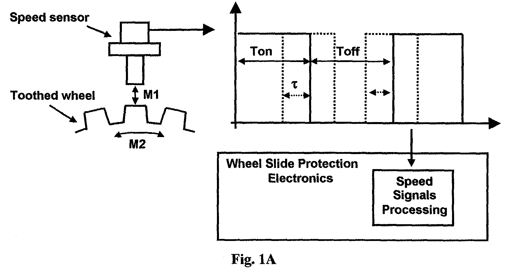
- FIG. 1A illustrates the basic principle of the invention.
- Speed sensors conventionally used in railway applications make use of magnetic or inductive sensing elements to detect the passage of the teeth of a ferro-magnetic toothed-wheel, which is mounted on the axle of the wheel-set.
- Some type of sensors generate sinusoidal output signals, some other include also amplification and zero-crossing detection circuitry (squarer circuit), as to directly generate a square wave output signal.
- squarer circuit zero-crossing detection circuitry
- the WSP Electronics usually includes a squarer circuit, or any other of the techniques well known to the skilled in the art, so as to allow the measurement of the frequency of the sensor's output signal. From the frequency value, it is then possible to compute the vehicle's speed, and monitor the rotation rate of each axle (typically, one WSP electronics controls 4 axles).
- V f ⁇ d / n (1)
- Figure 1A depicts also the effect resulting from the onset of the following vibration or disturbance modes:
- vibration modes are, in turn, triggered by shocks and-or vibrations due to defects of the wheel (wheel-flats), and-or bearings, and-or rail track.
- Their net effect on the output signal is the presence of jitter, indicated with the greek latter tau, ⁇ , in fig. 1A..
- Jitter is defined as a modulation of the pulse-width of the output signal. So that, by watching for example said output signal on an oscilloscope, and setting the trigger point on the rising edge, we would notice continuous small variations of the instant at which the falling edge occurs.
- the presence of vibration or disturbance modes M1 and-or M2 will result in a small modulation of ⁇ % .
- a minimal amount of jitter is unavoidable, and it will always be present due to manufacturing tolerances, and various other sources of background noise.
- this invention does not disregard this source of noise, but it includes specific means to accurately measure its value and periodicity of occurrence, with the declared aim to obtain precious diagnostics information about defects of the wheels, bearings, rail track.
- Figure 1B clearly illustrates the detection of a wheel-flat condition.
- the data shown correspond to recordings made on a tram vehicle, and which had a flat on the wheel-set whose speed sensor output signal was being monitored.
- the first complete wheel revolution corresponds to graph 1, after teeth 134 has passed by the sensor's head, the ⁇ % value of the next pulse is assigned to graph 2, and starting again at position 1 to end at position 134, ... and so on ... till the completion of graph 10.
- Figure 1B contains hence the measurements of ⁇ % for a total of 1340 consecutive pulses (i.e.: 10 consecutive wheel's revolutions). In this way it becomes very easy to visually compare variations in ⁇ %, and when they occur with respect to the periodicity of a complete wheel revolution (134 teeth). This particular sequence of wheel revolutions was recorded while the vehicle was accelerating from about 2 Km/h to about 10 Km/h.
- a defect on the rail track consisting in an excessive gap between two adjacent segments of track would also generate a similar spike.
- the spike will be a one-off occurrence (hence, with no correlation to the periodicity of a wheel revolution), but appearing on the output signals of all the 4 sensors monitored by one WSP Electronics.
- the time intervals between the occurrence of said 4 spikes will depend on the vehicle speed, and on the distance between the 4 axles.
- Figure 1C also shows the superposition of 10 graphs, corresponding to 10 consecutive wheel revolutions, but for a wheel-set with no damage. As no damage is present, no large spikes are observable. Even in this case it appears very clear that the small modulations (of ⁇ %) follow a pattern with the periodicity of a complete wheel revolution. This small modulations are due to manufacturing tolerances and mounting eccentricity. By comparing the recordings carried out at various times during the service life of the vehicle (let's say for example every 100000 Km), it is possible to monitor the evolution of axle bearings' defects or wear. This is a very useful feature for optimising preventive maintenance schedule.
- WSP Electronics which includes a plug-in board featuring a standard GSM-GPRS modem, and in addition a GPS module, useful to rely information about the location of detected rail track defects.
- the position of the 60% value can then be use as a reference to allow a meaningful superposition also of graphs recorded at different dates (once every few months, once a year, etc.).
- Figures 1B and 1C depicts the superposition of graphs representing ⁇ %, it shall be obvious to those skilled in the art that other equivalent representations are of direct derivation, such as: Toff / T, Toff / Ton, Ton / Toff , etc.
- the inventive step of this invention shall be understood as independent from the particular choices of "jitter parameter" representation and reference coordinates, rather it consists in the idea to implement means to enable monitoring, recording, and comparisons on said "jitter parameter", whatever the choice for its representation.
Abstract

Description
- The present invention describes a method and an apparatus to detect wheel flats in railway vehicles, allowing at the same time the monitoring of the evolution of axle bearings eccentricity and defects, as well as the detection of "sharp" rail track defects (excessive gaps and the like).
- Several devices are commercially available which already feature similar functions, although obtained by other means. Most notably, many devices belonging to the previous art rely on the use of vibration sensors, such as accelerometers. The output signals from such accelerometers are then processed and correlated to the wheel-set's rotation rate, with the aim to detect characteristic "signatures" on the signals, and which appears only at the occurrence of said defects. An important example of such previous art is detailed in General Electric Company's US patent n. 5,433,111.
- However, this type of devices are usually of very expensive implementation, requiring that an additional apparatus, and sensors, are purchased and installed on the vehicle.
- The present invention, instead, obtains similar diagnostics capabilities by introducing a novel way to process and filter the speed signals already available to the Wheel Slide Protection (WSP) Electronics (a sort of ABS for railway vehicles). No accelerometers or additional devices are required, other than the already present speed sensors and WSP Electronics, which shall now be designed to implement the method described herein.
- WSP electronics apparatuses are widely used on railway type brake equipments to prevent wheel lock conditions, which could be very damaging for the wheel-set. Their use is controlled and prescribed by international standards (UIC, International Union of Railways).
- It shall be remarked that the assignee of this invention, C-Sigma srl, is a manufacturer of railway type WSP Electronics apparatuses, and plans to embed this novel feature in all its future models.
- Although this invention is ideally suited for implementation in WSP electronics apparatuses, it can obviously be embodied also in other types of apparatuses, and in particular in self-contained devices. For example, the person skilled in the art can easily imagine ways to implement this method directly into a "smart" speed sensor.
- The inventive step of this invention consists in combining conventional toothed-wheel sensors with the capability to measure and record the jitter modulation on their output signals.
- Processing, and display by suitable means, of the recorded jitter measurements, allows then the detection of the defects described above. Figure 1A illustrates the basic principle of the invention. Speed sensors conventionally used in railway applications make use of magnetic or inductive sensing elements to detect the passage of the teeth of a ferro-magnetic toothed-wheel, which is mounted on the axle of the wheel-set. Some type of sensors generate sinusoidal output signals, some other include also amplification and zero-crossing detection circuitry (squarer circuit), as to directly generate a square wave output signal. When using a sinusoidal output type of sensor, the WSP Electronics usually includes a squarer circuit, or any other of the techniques well known to the skilled in the art, so as to allow the measurement of the frequency of the sensor's output signal. From the frequency value, it is then possible to compute the vehicle's speed, and monitor the rotation rate of each axle (typically, one WSP electronics controls 4 axles).
- Said n the number of teeth, d the wheel's diameter, and f the frequency of the speed sensor's output signal, then the vehicle's speed, V, is related to f by the following equation:
- Figure 1A depicts also the effect resulting from the onset of the following vibration or disturbance modes:
- Radial Mode M1, which results in small variations of the gap between the sensor's reading head and the toothed-wheel.
- Peripheral Mode M2, which results in small variations of the relative speed between the sensor's reading head and the toothed-wheel.
- Orthogonal Mode, along the direction orthogonal to M1 and M2, but less important because variations along this direction do not significantly modify the jitter modulation (the corresponding tooth dimension is larger that the sensor's reading head).
- These vibration modes are, in turn, triggered by shocks and-or vibrations due to defects of the wheel (wheel-flats), and-or bearings, and-or rail track. Their net effect on the output signal is the presence of jitter, indicated with the greek latter tau, τ , in fig. 1A.. Jitter is defined as a modulation of the pulse-width of the output signal. So that, by watching for example said output signal on an oscilloscope, and setting the trigger point on the rising edge, we would notice continuous small variations of the instant at which the falling edge occurs.
- If we define the duty cycle as, T = Ton + Toff :
- A minimal amount of jitter is unavoidable, and it will always be present due to manufacturing tolerances, and various other sources of background noise. In a typical application said minimal modulation is usually contained within ±1%, around a nominal value of α % = 50%.
- Apparatuses of the previous art disregard this modulation as merely one more source of noise, being only interested in the measurement of the frequency of the speed sensor's output signal.
- On the contrary, this invention does not disregard this source of noise, but it includes specific means to accurately measure its value and periodicity of occurrence, with the declared aim to obtain precious diagnostics information about defects of the wheels, bearings, rail track.
- Figure 1B clearly illustrates the detection of a wheel-flat condition. The data shown correspond to recordings made on a tram vehicle, and which had a flat on the wheel-set whose speed sensor output signal was being monitored. Figure 1B is actually the super-position of 10 graphs, each graph showing the measured value of α % (vertical axis) for each one of the consecutive pulses counted (horizontal axis). As one pulse corresponds to one tooth, and the number of teeth was in this case n = 134 , the horizontal axis spans from I to 134 counts. So, the first complete wheel revolution corresponds to graph 1, after teeth 134 has passed by the sensor's head, the α % value of the next pulse is assigned to graph 2, and starting again at position 1 to end at position 134, ... and so on ... till the completion of graph 10. Figure 1B contains hence the measurements of α % for a total of 1340 consecutive pulses (i.e.: 10 consecutive wheel's revolutions). In this way it becomes very easy to visually compare variations in α %, and when they occur with respect to the periodicity of a complete wheel revolution (134 teeth). This particular sequence of wheel revolutions was recorded while the vehicle was accelerating from about 2 Km/h to about 10 Km/h. It can be observed how the variations of α% are mostly contained within ± 1%, however all the 10 graphs show a large spike, up to ± 4%, at the same position on the wheel (on the graphs, between tooth 78 and 79). This spike is the characteristic "signature" of a flat wheel condition. In principle the recording of just one complete wheel revolution shall suffice to identify said characteristic "signature", however, to rule out possible spurious noise it is better to verify whether it also occurs with the same periodicity as that of a complete wheel revolution. So, it is advisable to record the measurements for at least 2 consecutive wheel revolutions (i.e.: for the case of a toothed-wheel with n = 134 , a minimum of 268 consecutive measurements).
- A defect on the rail track consisting in an excessive gap between two adjacent segments of track, would also generate a similar spike. In such case, the spike will be a one-off occurrence (hence, with no correlation to the periodicity of a wheel revolution), but appearing on the output signals of all the 4 sensors monitored by one WSP Electronics. The time intervals between the occurrence of said 4 spikes will depend on the vehicle speed, and on the distance between the 4 axles. When such a defect is detected, its location on the rail track can be reconstructed if the corresponding odometer value is recorded. At the next vehicle halt date and time are recorded, as well as the distance to the detected defect. The vehicle's journal shall then allow to reconstruct the approximate location of the defect. Alternatively, a more accurate way would record the geographical coordinates as generated by a GPS receiver module.
- Figure 1C also shows the superposition of 10 graphs, corresponding to 10 consecutive wheel revolutions, but for a wheel-set with no damage. As no damage is present, no large spikes are observable. Even in this case it appears very clear that the small modulations (of α%) follow a pattern with the periodicity of a complete wheel revolution. This small modulations are due to manufacturing tolerances and mounting eccentricity. By comparing the recordings carried out at various times during the service life of the vehicle (let's say for example every 100000 Km), it is possible to monitor the evolution of axle bearings' defects or wear. This is a very useful feature for optimising preventive maintenance schedule.
- Referring to the possibility to automatically detect characteristic "signatures" (spikes, and the like), the person skilled in the art could imagine several possible algorithms for their automatic detection. A typical example would be based on the definition of thresholds for deviations from average values, their time durations, and their correlation to a wheel revolution. However, this invention is not concerned with the particular choice of detection algorithms, therefore in the following we will assume that such an algorithm can be implemented in the apparatus, although we will make no reference to particular choices. When needed, we will generically refer to said detection threshold values as to "characteristic signatures detection thresholds" A typical apparatus embodying the invention would be composed of:
- 1. A conventional speed sensor with associated toothed-wheel.
- 2. A Speed Signals Processing circuit, easily realised by means of squarer circuits (for the measurements shown in Figures 1B and 1C, were the speed sensors themselves that already generated square output signals) feeding the CAPTURE input of a micro-controller (nowadays, most industry standard micro-controllers feature CAPTURE inputs). The CAPTURE input is used to measure the values of Ton and Toff , so as to allow the computation of α %. In the prototype of the new C-Sigma WSP Electronics, Ton and Toff are measured with 1µs resolution.
- 3. A section of memory in which to store said measurements α%. In the prototype measured values are stored in RAM as the difference with respect to α% =50%. This allows to shrink each measurement into a single 8 bits memory location.
- 4. Means to display said measurements, such as a graphic display, as it is the case for the new WSP Electronics of C-Sigma. Said measurements could also be made available (in addition, or in alternative) to an interface to external devices. Indeed, the prototype also allows the choice (accessible from a menu on the front panel display of the new WSP Electronics of C-Sigma) to send said measurements to the front panel RS232 or CAN interfaces, for continuous monitoring, display, and-or recording, on external apparatuses (such as, for example, a portable PC).
-
- Those skilled in the art will appreciate that several other useful features could be added, but which are of obvious derivation. An example is the addition of a user's choice for the speed range at which to start the recording of the α% measurements, or a choice for recording from the instant a button is pressed, and the like. Other examples include the addition of a modem to allow remote monitoring of the α% measurements, or the reception of remote SMS requests to respond with reply SMSs containing said α% measurements, and the like.
- Indeed, also these solutions are possible with the assignee's existing WSP Electronics, which includes a plug-in board featuring a standard GSM-GPRS modem, and in addition a GPS module, useful to rely information about the location of detected rail track defects..
- Furthermore, several ways can be imagined to implement algorithms, directly in the software running on the micro-controller, which could automatically recognize the characteristic "signatures" corresponding to the various defects, to then generate alarm flags and-or alarm signals of various type.
- It could also turned out useful to compare measurements of complete wheel revolutions, though this time NOT consecutive, for widely different speed values. This can be obtained by waiting, without recording, an integer number of complete wheel revolutions, before starting to record again when the next required speed value is reached. Alternatively, on the toothed-wheel, one or more teeth could be machined differently from all the others, and in a way to generate values of α% (for example 60%) easily recognizable from the mean value. Example: among a sequence of n-1 pulses with α %= 50 % suddenly appears a pulse with α %= 60 %, as in the sequence:
50%, 50%, 50%, 50%, ..... 50%, 60%, 40%, 50%, 50%, 50%, .... - The position of the 60% value can then be use as a reference to allow a meaningful superposition also of graphs recorded at different dates (once every few months, once a year, etc.).
- Such a trick allows to detect also the sense of rotation. In fact, by monitoring the sequence:
Ton / T, Toff / T, Ton / T, Toff / T, Ton / T, Toff / T, ..... - With the rotation in one sense the Speed Signals Processing will at some point measure Ton / T = 60 %, immediately followed by Toff / T=40 %. For the rotation in the other sense the Speed Signals Processing will before measure Toff / T=40 %, and immediately after Ton / T=60 %.
- Although Figures 1B and 1C depicts the superposition of graphs representing α%, it shall be obvious to those skilled in the art that other equivalent representations are of direct derivation, such as: Toff / T, Toff / Ton, Ton / Toff , etc.
- Other effective representations consist in plotting directly the value of τ, computed as the difference Ton - <Ton> (where <Ton> indicates the mean value over n pulses), or Toff - <Toff> , or Ton - Ton(1) (where Ton(1) indicates a reference value measured only once per revolution, or twice, etc.), Toff - Toff(1) , and the like.
- Indeed the number of possible ways to represents the effect of jitter is quite high, and the skilled in the art could find several reasons to prefer one way rather than another. To make the following description independent from the particular choice of jitter representation, we will collectively refer to any of the possible choices as to a generic "jitter parameter".
- Furthermore, each representation can be analysed with reference to different types of coordinates:
- Spatial coordinates, when the chosen reference points are spatial positions, such as, for example, the teeth count used in fig. 1B and 1C.
- Time coordinates, when reference is time, and characteristics spikes are correlated with the wheel's rotational rate.
- Frequency coordinates, when a transform (e.g.: Fourier, Z, Laplace, etc.) is applied to the recorded values, as to allow an analysis in the frequency domain, with correlations to the fundamental frequency defined by the wheel's rotational rate.
- The inventive step of this invention shall be understood as independent from the particular choices of "jitter parameter" representation and reference coordinates, rather it consists in the idea to implement means to enable monitoring, recording, and comparisons on said "jitter parameter", whatever the choice for its representation.
- Although the above description and examples refer to the application of the invention to the railway field, its application could be advantageous also in the automotive field, in particular for its capability to monitor defects and wear of bearings. More in general, this invention can be applied to all those applications (industrial machinery, etc.) where the combination toothed-wheel + sensor is used to monitor and/or measure rotational rates.
- It shall be appreciated that those skilled in the art, building on the features of the invention described above, now could easily imagine many changes, modifications, and-or substitutions. The following claims are intended to cover all such changes as fall within the spirit of the inventive step detailed in the above description.
Claims (5)
- Apparatus characterised in that it combines and processes, by means of a microprocessor or microcontroller, the output signals of wheel revolution sensors (such as conventional toothed-wheel sensors) with the measurement of a "jitter parameter" on said signals, to detect and monitor flats on railway wheels, defects and wear of bearings, defects on rail track. The detection of flats is achieved by verifying, visually or automatically, that spikes (i.e.: values clearly standing out of the average "jitter parameter" value) on graphs such as those of fig. 1B appear at integer multiples of a complete wheel's revolution. Said verifications can be made at a preferred range of the vehicle's speed and-or at several different speed values. The monitoring of the evolution of defects and wear in bearings is achieved by comparing, visually or automatically, graphs such those of fig. 1C, recorded at different times. Said comparisons can be made for a preferred range of the vehicle's speed and-or for several different speed values. To ease the comparison of measurements recorded at different times, a reference spike could be artificially introduced by machining in suitable ways one or more teeth, as detailed in the description. The detection of rail-track defects is achieved by verifying, visually or automatically, that spikes on graphs such as those of fig. 1B appear sequentially on all monitored speed signals, and with a time sequence defined by the vehicle's speed and by the distance between the axles on which the respective speed sensors are mounted. Although the listed capabilities refer to applications in the railway industry, it shall be apparent to those skilled in the art that said capabilities are of relevance also to automotive applications, as well as to industrial machinery applications.
- An apparatus as claimed in Claim 1, characterised in that a front panel display presents to the user one or more of the following choices: real time monitoring on a display of the "jitter parameter"; real time monitoring and/or recording on an external device of the "jitter parameter"; selection of speed values at which to start the recording of the "jitter parameter", for a selectable number of complete wheel revolutions; selection of the number of complete wheel revolutions to record and/or analyse; selection of "characteristic signatures detection thresholds" for the automatic generation of alarms when characteristic signatures appear. The above choices could also be made selectable from external devices, connected to the apparatus via industry standard interfaces (such as, for example: RS232, RS485, CAN bus, MVB bus, PROFI bus, etc.).
- An apparatus as claimed in Claim 1 and Claim 2, characterised in that a modem (very practical are GSM type, but also other types are possible) is added to allow remote real time monitoring of said "jitter parameter", as well as logging on a Central Server. Periodic comparisons, carried out on the logged data by a diagnostic module of the software running on said Central Server, will then allow the detection of defects and/or wear, as well as the monitoring of their evolution in time. Said modem remote connection could also be used to allow remote selection of the choices listed in Claim 2. The use of GSM modem would also allow the implementation of Central Server requests via SMS messages, to which the apparatus could reply also with SMS messages.
- An apparatus as claimed in Claim 3, characterised in that a GPS receiver module is added, as to allow accurate reporting on the exact location of detected rail-track defects.
- An apparatus as claimed in Claim 1, characterised in that the described functionalities are implemented directly into the speed sensor. Such a "smart sensor" would also feature the possibility to monitor in real time "jitter parameter" values on external devices, such as PCs, PDAs, User Terminals, and the like. The selection of choices, such as those described in Claim 2, could, also in this case, be made selectable from external devices, connected to said "smart sensor" via industry standard interfaces (such as, for example: RS232, RS485, CAN bus, MVB bus, PROFI bus, etc.).
Priority Applications (3)
| Application Number | Priority Date | Filing Date | Title |
|---|---|---|---|
| DE602004008735T DE602004008735T2 (en) | 2004-02-02 | 2004-02-02 | Device and method for detecting wheel flat, eccentric axle bearings and rail damage in a railway system |
| EP04425060A EP1559625B1 (en) | 2004-02-02 | 2004-02-02 | Apparatus and method for detecting wheel-flats, axle bearings eccentricity and rail-track defects in a railway system |
| AT04425060T ATE372242T1 (en) | 2004-02-02 | 2004-02-02 | DEVICE AND METHOD FOR DETECTING FLAT SPOT IN WHEELS, ECCENTRICITIES IN AXLE BEARINGS AND DAMAGE IN RAILS IN A RAILWAY SYSTEM |
Applications Claiming Priority (1)
| Application Number | Priority Date | Filing Date | Title |
|---|---|---|---|
| EP04425060A EP1559625B1 (en) | 2004-02-02 | 2004-02-02 | Apparatus and method for detecting wheel-flats, axle bearings eccentricity and rail-track defects in a railway system |
Publications (2)
| Publication Number | Publication Date |
|---|---|
| EP1559625A1 true EP1559625A1 (en) | 2005-08-03 |
| EP1559625B1 EP1559625B1 (en) | 2007-09-05 |
Family
ID=34639519
Family Applications (1)
| Application Number | Title | Priority Date | Filing Date |
|---|---|---|---|
| EP04425060A Expired - Lifetime EP1559625B1 (en) | 2004-02-02 | 2004-02-02 | Apparatus and method for detecting wheel-flats, axle bearings eccentricity and rail-track defects in a railway system |
Country Status (3)
| Country | Link |
|---|---|
| EP (1) | EP1559625B1 (en) |
| AT (1) | ATE372242T1 (en) |
| DE (1) | DE602004008735T2 (en) |
Cited By (8)
| Publication number | Priority date | Publication date | Assignee | Title |
|---|---|---|---|---|
| EP1498334A3 (en) * | 2003-07-17 | 2005-11-23 | ArvinMeritor Technology, LLC | Wheel end condition detection system |
| WO2008080211A1 (en) * | 2006-12-28 | 2008-07-10 | Bce Inc. | Apparatus, system and method for tracking a rotatable object |
| DE102008020378A1 (en) * | 2008-04-23 | 2009-11-19 | Siemens Aktiengesellschaft | Method for detection of imbalance in wheels of wheel rail systems, involves providing one of two wheels having axes of driving train as freewheeling for time interval for avoiding wheel spin |
| CN105021412A (en) * | 2014-04-18 | 2015-11-04 | 上海汽车集团股份有限公司 | Automobile shock absorber performance test method and automobile shock absorber performance test system |
| US9728016B2 (en) | 2014-01-06 | 2017-08-08 | General Electric Company | Wheel monitoring system and method |
| EP3835716A1 (en) | 2019-12-13 | 2021-06-16 | ALSTOM Transport Technologies | Method for controlling wheel deformation, associated device and system including such a device |
| CN114056381A (en) * | 2021-11-24 | 2022-02-18 | 西南交通大学 | Railway vehicle wheel flat scar monitoring method |
| US11472450B2 (en) | 2016-12-21 | 2022-10-18 | Knorr-Bremse Systeme für Schienenfahrzeuge GmbH | Method and control unit for detection of derailment on the basis of wheel speed signals |
Families Citing this family (2)
| Publication number | Priority date | Publication date | Assignee | Title |
|---|---|---|---|---|
| DE102012221856A1 (en) * | 2012-11-29 | 2014-06-05 | Leonhard Weiss Gmbh & Co. Kg | System for detecting flat spot in rim of wheel of rail vehicle i.e. track laying vehicle, has evaluator evaluating blocking of rim, and providing evaluation as event, and transmission unit transmitting event to predetermined location |
| RU2662304C2 (en) * | 2016-12-26 | 2018-07-25 | Общество с ограниченной ответственностью "Энергосервис" (ООО "Энергосервис") | Gear wheel teeth recording and counting device |
Citations (6)
| Publication number | Priority date | Publication date | Assignee | Title |
|---|---|---|---|---|
| CH668129A5 (en) * | 1985-05-10 | 1988-11-30 | Stabeg Apparatebau Gmbh | Measurement appts. for rotating rate of railway vehicle wheel axle - has pole wheel attached to wheel axle via flexible coupling and pulse generating probe |
| US5433111A (en) * | 1994-05-05 | 1995-07-18 | General Electric Company | Apparatus and method for detecting defective conditions in railway vehicle wheels and railtracks |
| DE19835041C1 (en) * | 1998-08-04 | 1999-08-05 | Werner Michael | Monitoring arrangement for wheel processes on high speed rail vehicles |
| DE19827271A1 (en) * | 1998-06-19 | 1999-12-23 | Andreas Mueller | Sensor supported ON LINE determination system with evaluation of wheel and track related data during train travel |
| DE10020519A1 (en) * | 2000-04-19 | 2001-10-31 | Deutsche Bahn Ag | Drive characteristics monitoring method for train, involves judging damage of vehicle component when deviation of oscillation value distribution of filtered course from normal distribution, equals preset value |
| US20030231014A1 (en) * | 2002-06-17 | 2003-12-18 | Skf Industrie S.P.A. | Surveying device for the running parameters of railway bearings |
-
2004
- 2004-02-02 EP EP04425060A patent/EP1559625B1/en not_active Expired - Lifetime
- 2004-02-02 AT AT04425060T patent/ATE372242T1/en not_active IP Right Cessation
- 2004-02-02 DE DE602004008735T patent/DE602004008735T2/en not_active Expired - Lifetime
Patent Citations (6)
| Publication number | Priority date | Publication date | Assignee | Title |
|---|---|---|---|---|
| CH668129A5 (en) * | 1985-05-10 | 1988-11-30 | Stabeg Apparatebau Gmbh | Measurement appts. for rotating rate of railway vehicle wheel axle - has pole wheel attached to wheel axle via flexible coupling and pulse generating probe |
| US5433111A (en) * | 1994-05-05 | 1995-07-18 | General Electric Company | Apparatus and method for detecting defective conditions in railway vehicle wheels and railtracks |
| DE19827271A1 (en) * | 1998-06-19 | 1999-12-23 | Andreas Mueller | Sensor supported ON LINE determination system with evaluation of wheel and track related data during train travel |
| DE19835041C1 (en) * | 1998-08-04 | 1999-08-05 | Werner Michael | Monitoring arrangement for wheel processes on high speed rail vehicles |
| DE10020519A1 (en) * | 2000-04-19 | 2001-10-31 | Deutsche Bahn Ag | Drive characteristics monitoring method for train, involves judging damage of vehicle component when deviation of oscillation value distribution of filtered course from normal distribution, equals preset value |
| US20030231014A1 (en) * | 2002-06-17 | 2003-12-18 | Skf Industrie S.P.A. | Surveying device for the running parameters of railway bearings |
Cited By (11)
| Publication number | Priority date | Publication date | Assignee | Title |
|---|---|---|---|---|
| EP1498334A3 (en) * | 2003-07-17 | 2005-11-23 | ArvinMeritor Technology, LLC | Wheel end condition detection system |
| US7228932B2 (en) | 2003-07-17 | 2007-06-12 | Arvinmeritor Technology, Llc | Wheel end condition detection system |
| WO2008080211A1 (en) * | 2006-12-28 | 2008-07-10 | Bce Inc. | Apparatus, system and method for tracking a rotatable object |
| US8424374B2 (en) | 2006-12-28 | 2013-04-23 | Bce Inc. | Apparatus, system and method for tracking a rotatable object |
| DE102008020378A1 (en) * | 2008-04-23 | 2009-11-19 | Siemens Aktiengesellschaft | Method for detection of imbalance in wheels of wheel rail systems, involves providing one of two wheels having axes of driving train as freewheeling for time interval for avoiding wheel spin |
| US9728016B2 (en) | 2014-01-06 | 2017-08-08 | General Electric Company | Wheel monitoring system and method |
| CN105021412A (en) * | 2014-04-18 | 2015-11-04 | 上海汽车集团股份有限公司 | Automobile shock absorber performance test method and automobile shock absorber performance test system |
| US11472450B2 (en) | 2016-12-21 | 2022-10-18 | Knorr-Bremse Systeme für Schienenfahrzeuge GmbH | Method and control unit for detection of derailment on the basis of wheel speed signals |
| EP3835716A1 (en) | 2019-12-13 | 2021-06-16 | ALSTOM Transport Technologies | Method for controlling wheel deformation, associated device and system including such a device |
| FR3104527A1 (en) | 2019-12-13 | 2021-06-18 | Alstom Transport Technologies | Method for controlling wheel deformation, associated device and system comprising such a device |
| CN114056381A (en) * | 2021-11-24 | 2022-02-18 | 西南交通大学 | Railway vehicle wheel flat scar monitoring method |
Also Published As
| Publication number | Publication date |
|---|---|
| ATE372242T1 (en) | 2007-09-15 |
| DE602004008735D1 (en) | 2007-10-18 |
| DE602004008735T2 (en) | 2008-06-12 |
| EP1559625B1 (en) | 2007-09-05 |
Similar Documents
| Publication | Publication Date | Title |
|---|---|---|
| EP3509927B1 (en) | A railway track condition monitoring system for detecting a partial or complete disruption of a rail of the railway track | |
| EP1559625A1 (en) | Apparatus and method for detecting wheel-flats, axle bearings eccentricity and rail-track defects in a railway system | |
| US4415979A (en) | Method and apparatus for detecting the presence of an animate body in an inanimate mobile structure | |
| Ki et al. | Model for accurate speed measurement using double-loop detectors | |
| US4129276A (en) | Technique for the detection of flat wheels on railroad cars by acoustical measuring means | |
| US6204658B1 (en) | Method for evaluating an output signal of a rotational sensing device | |
| US5463373A (en) | Device for verifying disturbances in signal transmission in motor vehicles | |
| JP2007114204A (en) | Method and system for detecting and measuring disturbance about frequency of rotational speed of rotor | |
| CA2276672A1 (en) | Device for monitoring pollution caused by motor vehicles in an urban area | |
| JP2014167788A (en) | Method for recording vehicle-relevant data, in particular for detecting and evaluating minor damage, sensor device to be installed in vehicle, and vehicle having the sensor device for carrying out the method | |
| CN109278796A (en) | A kind of vehicular wheel out of round degree detection system | |
| US5408179A (en) | Method and apparatus for analying traffic and a sensor therefor | |
| CN112428753B (en) | Vehicle tire abnormity identification method and device, electronic equipment and storage medium | |
| US6816816B2 (en) | Transducer fault detection system using slew rate measurements: apparatus and method | |
| CN110988624B (en) | Detection method and system for intermittent partial discharge signal | |
| US20240110937A1 (en) | Device for ascertaining data for determining a velocity of a vehicle, evaluation device, and method for this purpose | |
| US20030187605A1 (en) | Method and apparatus for detecting hot rail car surfaces | |
| US6453250B1 (en) | Method and apparatus for detection of missing pulses from a pulse train | |
| WO2001094175A1 (en) | Method and apparatus for detecting roundness defects in a railway vehicle wheel | |
| CN103914889A (en) | System and method for carrying out anomaly detection on behavior of collecting vehicle speed | |
| US10713867B2 (en) | Sensorless prediction and storage of vehicle dynamics information | |
| KR102247150B1 (en) | Automatic ultrasonic detection apparatus for electric power facility using drone | |
| Ki | Speed-measurement model utilising embedded triple-loop sensors | |
| JP2018527577A (en) | How to determine the speed of a rail vehicle | |
| RU67052U1 (en) | DEVICE FOR MEASURING AND MONITORING PARAMETERS OF DEVICES OF RAILWAY AUTOMATION AND TELEMECHANICS |
Legal Events
| Date | Code | Title | Description |
|---|---|---|---|
| PUAI | Public reference made under article 153(3) epc to a published international application that has entered the european phase |
Free format text: ORIGINAL CODE: 0009012 |
|
| AK | Designated contracting states |
Kind code of ref document: A1 Designated state(s): AT BE BG CH CY CZ DE DK EE ES FI FR GB GR HU IE IT LI LU MC NL PT RO SE SI SK TR |
|
| AX | Request for extension of the european patent |
Extension state: AL LT LV MK |
|
| AKX | Designation fees paid | ||
| 17P | Request for examination filed |
Effective date: 20060216 |
|
| RBV | Designated contracting states (corrected) |
Designated state(s): AT BE BG CH CY CZ DE DK EE ES FI FR GB GR HU IE IT LI LU MC NL PT RO SE SI SK TR |
|
| REG | Reference to a national code |
Ref country code: DE Ref legal event code: 8566 |
|
| GRAP | Despatch of communication of intention to grant a patent |
Free format text: ORIGINAL CODE: EPIDOSNIGR1 |
|
| GRAS | Grant fee paid |
Free format text: ORIGINAL CODE: EPIDOSNIGR3 |
|
| GRAA | (expected) grant |
Free format text: ORIGINAL CODE: 0009210 |
|
| AK | Designated contracting states |
Kind code of ref document: B1 Designated state(s): AT BE BG CH CY CZ DE DK EE ES FI FR GB GR HU IE IT LI LU MC NL PT RO SE SI SK TR |
|
| REG | Reference to a national code |
Ref country code: GB Ref legal event code: FG4D |
|
| REG | Reference to a national code |
Ref country code: CH Ref legal event code: EP |
|
| REF | Corresponds to: |
Ref document number: 602004008735 Country of ref document: DE Date of ref document: 20071018 Kind code of ref document: P |
|
| REG | Reference to a national code |
Ref country code: IE Ref legal event code: FG4D |
|
| PG25 | Lapsed in a contracting state [announced via postgrant information from national office to epo] |
Ref country code: ES Free format text: LAPSE BECAUSE OF FAILURE TO SUBMIT A TRANSLATION OF THE DESCRIPTION OR TO PAY THE FEE WITHIN THE PRESCRIBED TIME-LIMIT Effective date: 20071216 Ref country code: FI Free format text: LAPSE BECAUSE OF FAILURE TO SUBMIT A TRANSLATION OF THE DESCRIPTION OR TO PAY THE FEE WITHIN THE PRESCRIBED TIME-LIMIT Effective date: 20070905 |
|
| PG25 | Lapsed in a contracting state [announced via postgrant information from national office to epo] |
Ref country code: LI Free format text: LAPSE BECAUSE OF FAILURE TO SUBMIT A TRANSLATION OF THE DESCRIPTION OR TO PAY THE FEE WITHIN THE PRESCRIBED TIME-LIMIT Effective date: 20070905 Ref country code: CH Free format text: LAPSE BECAUSE OF FAILURE TO SUBMIT A TRANSLATION OF THE DESCRIPTION OR TO PAY THE FEE WITHIN THE PRESCRIBED TIME-LIMIT Effective date: 20070905 Ref country code: AT Free format text: LAPSE BECAUSE OF FAILURE TO SUBMIT A TRANSLATION OF THE DESCRIPTION OR TO PAY THE FEE WITHIN THE PRESCRIBED TIME-LIMIT Effective date: 20070905 |
|
| NLV1 | Nl: lapsed or annulled due to failure to fulfill the requirements of art. 29p and 29m of the patents act | ||
| PG25 | Lapsed in a contracting state [announced via postgrant information from national office to epo] |
Ref country code: BE Free format text: LAPSE BECAUSE OF FAILURE TO SUBMIT A TRANSLATION OF THE DESCRIPTION OR TO PAY THE FEE WITHIN THE PRESCRIBED TIME-LIMIT Effective date: 20070905 |
|
| REG | Reference to a national code |
Ref country code: CH Ref legal event code: PL |
|
| ET | Fr: translation filed | ||
| PG25 | Lapsed in a contracting state [announced via postgrant information from national office to epo] |
Ref country code: NL Free format text: LAPSE BECAUSE OF FAILURE TO SUBMIT A TRANSLATION OF THE DESCRIPTION OR TO PAY THE FEE WITHIN THE PRESCRIBED TIME-LIMIT Effective date: 20070905 Ref country code: GR Free format text: LAPSE BECAUSE OF FAILURE TO SUBMIT A TRANSLATION OF THE DESCRIPTION OR TO PAY THE FEE WITHIN THE PRESCRIBED TIME-LIMIT Effective date: 20071206 |
|
| PG25 | Lapsed in a contracting state [announced via postgrant information from national office to epo] |
Ref country code: PT Free format text: LAPSE BECAUSE OF FAILURE TO SUBMIT A TRANSLATION OF THE DESCRIPTION OR TO PAY THE FEE WITHIN THE PRESCRIBED TIME-LIMIT Effective date: 20080206 Ref country code: CZ Free format text: LAPSE BECAUSE OF FAILURE TO SUBMIT A TRANSLATION OF THE DESCRIPTION OR TO PAY THE FEE WITHIN THE PRESCRIBED TIME-LIMIT Effective date: 20070905 Ref country code: SK Free format text: LAPSE BECAUSE OF FAILURE TO SUBMIT A TRANSLATION OF THE DESCRIPTION OR TO PAY THE FEE WITHIN THE PRESCRIBED TIME-LIMIT Effective date: 20070905 |
|
| PG25 | Lapsed in a contracting state [announced via postgrant information from national office to epo] |
Ref country code: SE Free format text: LAPSE BECAUSE OF FAILURE TO SUBMIT A TRANSLATION OF THE DESCRIPTION OR TO PAY THE FEE WITHIN THE PRESCRIBED TIME-LIMIT Effective date: 20071205 Ref country code: RO Free format text: LAPSE BECAUSE OF FAILURE TO SUBMIT A TRANSLATION OF THE DESCRIPTION OR TO PAY THE FEE WITHIN THE PRESCRIBED TIME-LIMIT Effective date: 20070905 |
|
| PLBE | No opposition filed within time limit |
Free format text: ORIGINAL CODE: 0009261 |
|
| STAA | Information on the status of an ep patent application or granted ep patent |
Free format text: STATUS: NO OPPOSITION FILED WITHIN TIME LIMIT |
|
| PG25 | Lapsed in a contracting state [announced via postgrant information from national office to epo] |
Ref country code: DK Free format text: LAPSE BECAUSE OF FAILURE TO SUBMIT A TRANSLATION OF THE DESCRIPTION OR TO PAY THE FEE WITHIN THE PRESCRIBED TIME-LIMIT Effective date: 20070905 |
|
| 26N | No opposition filed |
Effective date: 20080606 |
|
| PG25 | Lapsed in a contracting state [announced via postgrant information from national office to epo] |
Ref country code: MC Free format text: LAPSE BECAUSE OF NON-PAYMENT OF DUE FEES Effective date: 20080228 |
|
| PG25 | Lapsed in a contracting state [announced via postgrant information from national office to epo] |
Ref country code: IE Free format text: LAPSE BECAUSE OF NON-PAYMENT OF DUE FEES Effective date: 20080204 Ref country code: EE Free format text: LAPSE BECAUSE OF FAILURE TO SUBMIT A TRANSLATION OF THE DESCRIPTION OR TO PAY THE FEE WITHIN THE PRESCRIBED TIME-LIMIT Effective date: 20070905 |
|
| PG25 | Lapsed in a contracting state [announced via postgrant information from national office to epo] |
Ref country code: SI Free format text: LAPSE BECAUSE OF FAILURE TO SUBMIT A TRANSLATION OF THE DESCRIPTION OR TO PAY THE FEE WITHIN THE PRESCRIBED TIME-LIMIT Effective date: 20070905 |
|
| PG25 | Lapsed in a contracting state [announced via postgrant information from national office to epo] |
Ref country code: CY Free format text: LAPSE BECAUSE OF FAILURE TO SUBMIT A TRANSLATION OF THE DESCRIPTION OR TO PAY THE FEE WITHIN THE PRESCRIBED TIME-LIMIT Effective date: 20070905 |
|
| PG25 | Lapsed in a contracting state [announced via postgrant information from national office to epo] |
Ref country code: BG Free format text: LAPSE BECAUSE OF FAILURE TO SUBMIT A TRANSLATION OF THE DESCRIPTION OR TO PAY THE FEE WITHIN THE PRESCRIBED TIME-LIMIT Effective date: 20071205 |
|
| PG25 | Lapsed in a contracting state [announced via postgrant information from national office to epo] |
Ref country code: LU Free format text: LAPSE BECAUSE OF NON-PAYMENT OF DUE FEES Effective date: 20080202 Ref country code: HU Free format text: LAPSE BECAUSE OF FAILURE TO SUBMIT A TRANSLATION OF THE DESCRIPTION OR TO PAY THE FEE WITHIN THE PRESCRIBED TIME-LIMIT Effective date: 20080306 |
|
| PG25 | Lapsed in a contracting state [announced via postgrant information from national office to epo] |
Ref country code: TR Free format text: LAPSE BECAUSE OF FAILURE TO SUBMIT A TRANSLATION OF THE DESCRIPTION OR TO PAY THE FEE WITHIN THE PRESCRIBED TIME-LIMIT Effective date: 20070905 |
|
| REG | Reference to a national code |
Ref country code: FR Ref legal event code: ST Effective date: 20101029 |
|
| REG | Reference to a national code |
Ref country code: FR Ref legal event code: RN |
|
| PG25 | Lapsed in a contracting state [announced via postgrant information from national office to epo] |
Ref country code: FR Free format text: LAPSE BECAUSE OF NON-PAYMENT OF DUE FEES Effective date: 20100301 |
|
| REG | Reference to a national code |
Ref country code: FR Ref legal event code: FC |
|
| PGFP | Annual fee paid to national office [announced via postgrant information from national office to epo] |
Ref country code: FR Payment date: 20110314 Year of fee payment: 8 Ref country code: IT Payment date: 20110228 Year of fee payment: 8 Ref country code: DE Payment date: 20110228 Year of fee payment: 8 |
|
| PGRI | Patent reinstated in contracting state [announced from national office to epo] |
Ref country code: FR Effective date: 20110310 |
|
| PGFP | Annual fee paid to national office [announced via postgrant information from national office to epo] |
Ref country code: GB Payment date: 20110225 Year of fee payment: 8 |
|
| GBPC | Gb: european patent ceased through non-payment of renewal fee |
Effective date: 20120202 |
|
| REG | Reference to a national code |
Ref country code: FR Ref legal event code: ST Effective date: 20121031 |
|
| PG25 | Lapsed in a contracting state [announced via postgrant information from national office to epo] |
Ref country code: IT Free format text: LAPSE BECAUSE OF NON-PAYMENT OF DUE FEES Effective date: 20120202 |
|
| REG | Reference to a national code |
Ref country code: DE Ref legal event code: R119 Ref document number: 602004008735 Country of ref document: DE Effective date: 20120901 |
|
| PG25 | Lapsed in a contracting state [announced via postgrant information from national office to epo] |
Ref country code: GB Free format text: LAPSE BECAUSE OF NON-PAYMENT OF DUE FEES Effective date: 20120202 Ref country code: FR Free format text: LAPSE BECAUSE OF NON-PAYMENT OF DUE FEES Effective date: 20120229 |
|
| PG25 | Lapsed in a contracting state [announced via postgrant information from national office to epo] |
Ref country code: DE Free format text: LAPSE BECAUSE OF NON-PAYMENT OF DUE FEES Effective date: 20120901 |