EP1559565A1 - Tape printer - Google Patents
Tape printer Download PDFInfo
- Publication number
- EP1559565A1 EP1559565A1 EP04030299A EP04030299A EP1559565A1 EP 1559565 A1 EP1559565 A1 EP 1559565A1 EP 04030299 A EP04030299 A EP 04030299A EP 04030299 A EP04030299 A EP 04030299A EP 1559565 A1 EP1559565 A1 EP 1559565A1
- Authority
- EP
- European Patent Office
- Prior art keywords
- text
- print label
- image
- image display
- Prior art date
- Legal status (The legal status is an assumption and is not a legal conclusion. Google has not performed a legal analysis and makes no representation as to the accuracy of the status listed.)
- Granted
Links
Images




Classifications
-
- G—PHYSICS
- G06—COMPUTING OR CALCULATING; COUNTING
- G06F—ELECTRIC DIGITAL DATA PROCESSING
- G06F40/00—Handling natural language data
- G06F40/10—Text processing
- G06F40/103—Formatting, i.e. changing of presentation of documents
- G06F40/106—Display of layout of documents; Previewing
-
- B—PERFORMING OPERATIONS; TRANSPORTING
- B41—PRINTING; LINING MACHINES; TYPEWRITERS; STAMPS
- B41J—TYPEWRITERS; SELECTIVE PRINTING MECHANISMS, i.e. MECHANISMS PRINTING OTHERWISE THAN FROM A FORME; CORRECTION OF TYPOGRAPHICAL ERRORS
- B41J3/00—Typewriters or selective printing or marking mechanisms characterised by the purpose for which they are constructed
- B41J3/407—Typewriters or selective printing or marking mechanisms characterised by the purpose for which they are constructed for marking on special material
- B41J3/4075—Tape printers; Label printers
Definitions
- the present invention relates to a tape printer for displaying an image of part of a print label produced by cutting off a printed print tape.
- a text of document data such as characters entered and created from a keyboard or the like is printed on a print tape, and the tape is cut off to produce a print label, and it may also include an image display function for displaying the image of the print label on a display screen.
- the image display range of print label can be moved, and the size and position of characters to be produced later on the print label can be confirmed.
- large blanks are set at both ends of the print label, or many spaces are inserted at the beginning or end of the text to be printed, if the image of characters and the like of the print label is displayed, the image of the beginning and end of print label is not displayed, the user observing this image display may find it difficult to judge which part of the image of the print label is being displayed.
- the present invention has been made in view of the above circumstances and has an object to overcome the above problems and to provide a tape printer capable of displaying an image easy to understand for users.
- a tape printer comprising text creating means for creating a text composed of document data such as characters, printing means for printing the text on a lengthy print tape in a state of having a forward blank positioned ahead of the text, cutting means for cutting off the print tape having the text printed by the printing means in a state of having the forward blank and a backward blank positioned behind the text, thereby producing a print label, and image display means for displaying an image of the print label, further comprising: first display control means for displaying the image of a leading end portion of the print label on the image display means by disposing an image of beginning data of the text in a final position of the image display means.
- the image display means for displaying an image of a print label since the image of the leading end portion of the print label is displayed in a state of the image of the beginning data of the text to be printed on the print label being disposed at a final position of the image display means, if a large blank is set at the leading end of the print label, it is possible to avoid displaying the image of blank only at the leading end portion of the print label as initial display state. Therefore, in the initial display state of the image display means, characters and the like corresponding to the beginning data of the text to be printed on the print label can be always displayed, and the image display range of the print label can be instantly known, so that the image easy to understand for the user can be displayed.
- the present invention provides a tape printer comprising text creating means for creating a text composed of document data such as characters, printing means for printing the text on a lengthy print tape in a state of having a forward blank positioned ahead of the text, cutting means for cutting off the print tape having the text printed by the printing means in a state of having the forward blank and a backward blank positioned behind the text, thereby producing a print label, and image display means for displaying an image of the print label, further comprising: a lengthy display region held in part of the image display means to represent an overall contour of the print label; and second display control means for displaying a display range of the print label in the image display means in the display region in a relative regional relation with the overall contour of the print label.
- the display range of this print label is displayed solid in a relative regional relation with the entire contour of the print label. Therefore, if only the blank or space of the print label is displayed in image, the image display range of the print label can be instantly known through the solid display area in the lengthy display region, so that the image easy to understand for the user can be displayed.
- the present invention provides a tape printer comprising text creating means for creating a text composed of document data such as characters, printing means for printing the text on a lengthy print tape in a state of having a forward blank positioned ahead of the text, cutting means for cutting off the print tape having the text printed by the printing means in a state of having the forward blank and a backward blank positioned behind the text, thereby producing a print label, and image display means for displaying an image of the print label, further comprising: first display control means for displaying an image of a leading end portion of the print label on the image display means by disposing an image of beginning data of the text in a final position of the image display means; a lengthy display region held in part of the image display means to represent an overall contour of the print label; and second display control means for displaying a display range of the print label in the image display means in the display region in a relative regional relation with the overall contour of the print label.
- the image display means for displaying an image of a print label since the image of the leading end portion of the print label is displayed in a state of the image of the beginning data of the text to be printed on the print label being disposed at a final position of the image display means, if a large blank is set at the leading end of the print label, it is possible to avoid displaying the image of blank only at the leading end portion of the print label as initial display state. Therefore, in the initial display state of the image display means, characters and the like corresponding to the beginning data of the text to be printed on the print label can be always displayed, and the image display range of the print label can be instantly known, so that the image easy to understand for the user can be displayed.
- the tape printer of the invention in image display means for displaying an image of a print label, in a lengthy display region held for showing an entire contour of this print label, the display range of this print label is displayed solid in a relative regional relation with the entire contour of the print label. Therefore, if only the blank or space of the print label is displayed in image, the image display region of the print label can be instantly known through the solid display area in the lengthy display region, so that the image easy to understand for the user can be displayed.
- the tape printer of the preferred embodiment for example, if desired to produce a print label P printing text content of ABC as shown in Fig. 19, the image of this print label P can be displayed on a liquid crystal display 7, but in the initial display state of the image display, as shown in the diagram, the letter A corresponding to the beginning data of the text is displayed in a final position of the liquid crystal display 7.
- the tape printer of the preferred embodiment it can be set whether or not to include space data as beginning data of the text.
- space data For the convenience of explanation, supposing the space to be ⁇ , if the text content is ⁇ ABC, when desired to set by including the space data, the space ⁇ corresponding to the beginning data of the text comes to the final position of the liquid crystal display 7, and the letters ABC are not displayed in the initial display state of image display on the liquid crystal display 7.
- the initial display state of image display on the liquid crystal display 7 is the same as shown in Fig. 19, and letter A comes to the final position of the liquid crystal display 7.
- a lengthy ruler 101 corresponding to an entire contour of the print label P is provided beneath the liquid crystal display 7.
- this solid display region 102 indicates the range of image display of the print label P on the liquid crystal display 7 in a relative positional relation with the lengthy ruler 101. Therefore, when the image display range on the liquid crystal display 7 is displayed in scroll at the right side, the solid display region 102 in the lengthy ruler 101 is moved to the right side according to the scroll display to the right side, and when the image display range on the liquid crystal display 7 is displayed in scroll at the left side, the solid display region 102 in the lengthy ruler 101 is moved to the left side according to the scroll display to the left side. Therefore, in the liquid crystal display 7, the range of print label P presently displayed in image can be clarified.
- a first display region 103 which indicates distance L1 from the leading end S1 of print label P to the display start position S2 of print label P in the unit of millimeters. Therefore, when the image display range on the liquid crystal display 7 is displayed in scroll to the right side, according to the scroll display to the right side, the numerical value displayed in the unit of millimeters in the first display region 103 increases, and when the image display range on the liquid crystal display 7 is displayed in scroll to the left side, according to the scroll display to the left side, the numerical value displayed in the unit of millimeters in the first display region 103 decreases.
- a second display region 104 which indicates distance L2 from the leading end S1 to the final end S3 of the print label P, that is, the overall length of the print label P, in the unit of millimeters.
- reference numeral R1 indicates the start position of solid display region 102 in the lengthy ruler 101, and it is described in detail below.
- hatching display can be selected in the blank portion of print label P displayed in image in the liquid crystal display 7, and by selecting it, the blank portion of the print label P can be clearly displayed. Therefore, in the initial display state of image display shown in Fig. 19, for example, when this selection is executed, the display state is changed to Fig. 21, and out of the forward blank positioned before the text ABC, an image display portion 105 on the liquid crystal display 7 is displayed by hatching.
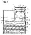
- Fig. 1 is a plan view of tape printer shown by opening a pivoting cover of a tape cassette compartment.
- the tape printer 1 comprises a keyboard 6 including text input keys 2 for entering characters and the like, a print key 3, a blank setting key 4, a return key 5 for feeding line and commanding execution of each process, an image display setting key 111, an image display key 112, two scroll keys 113, an image display end key 114, and other function keys, a liquid crystal display 7 for displaying the characters and the like entered from the keyboard 6, and a cassette compartment 8 for accommodating a tape cassette 30 described below.
- the cassette compartment 8 incorporates a ribbon take-up shaft 9 which is rotated and driven by a pulse motor 75 described later, and takes up a thermal ink ribbon 34 by turning a ribbon take-up spool 38 of tape cassette 30, and also a tape feed roller shaft 10, which is planted obliquely ahead thereof (keyboard 6 side), for rotating a tape feed roller 43 described below, as being rotated and driven by way of a proper transmission mechanism from the pulse motor 75. Further ahead of the cassette compartment 8, a thermal head 11 is affixed for printing on a film tape 32 described below by way of the thermal ink ribbon 34.
- the cassette compartment 8 is opened or closed by the pivoting cover 12 rotatably installed behind the tape printer 1, and the tape cassette 30 is exchanged in open state.
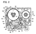
- Fig. 2 is a plan view showing a state of the tape cassette 30 accommodated in the cassette compartment 8 (shown by removing an upper case of the tape cassette 8), and Fig. 3 is its partly magnified plan view.
- a lower case 31 comprises a tape spool 33 with a wound transparent film tape 32, a ribbon spool 35 with a wound thermal ink ribbon 34, and an adhesive tape spool 37 having a double side adhesive tape 36 with parting paper wound with the parting paper side outside, and these spools 33, 35, 37 are rotatably supported by cooperation with support units provided in the lower side of the upper case not shown.
- a ribbon take-up spool 38 is similarly supported rotatably, and the ribbon take-up spool 38 is engaged with the ribbon take-up shaft 9, and takes up the thermal ink ribbon 34 used by printing by driving of the ribbon take-up shaft 9.
- the thermal head 11 is disposed in a recess 39 provided in the lower case 31, and a platen roller 40 rotatably supported by a roller holder H described later is disposed opposite to the thermal head 11 in pressing contact state.
- the thermal head 11 has multiple heating elements (128 heating elements in the thermal head 11 of the 'preferred embodiment), and is designed to print characters and the like on the film tape 32 by way of the thermal ink ribbon 34.
- a tape pressing roller 42 is rotatably supported, and a tape feed roller 43 rotatably supported by the roller holder H described later is disposed opposite to the tape pressing roller 42 in pressing contact state.
- roller holder H In the cassette compartment 8, ahead of the tape cassette 30 (lower side in Fig. 1 and Fig. 2), the roller holder H is pivoted rotatably by a support shaft 44, and this roller holder H is changed over between print position and release position by manual changeover mechanism not shown (print position is shown in Fig. 1 and Fig. 2).
- the roller holder H rotatably supports the platen roller 40 and tape feed roller 43 as shown in Fig. 3, and is disposed tightly to the thermal head 11 and pressing roller 42.
- the platen roller 40 is supported rotatably about a rotary shaft 46 planted on a holder member 45, and the holder member 45 is pressed to the thermal head 11 by means of an elastic spring 47 loaded between it and the rear wall R of the roller holder H.
- the tape feed roller 43 is supported rotatably about a rotary shaft 49 planted on a holder member 48, and the holder member 48 is pressed to the pressing roller 42 by means of an elastic spring 50 loaded between it and the rear wall R of the roller holder H.
- the tape feed roller 43 is rotated and driven by the tape feed roller shaft 10, and at the same time the pressing roller 42 is rotated and driven in cooperation with the tape feed roller 43 by a gear mechanism not shown.
- an intermediate roller 51 is supported rotatably on a holder member 52 by way of a rotary shaft 53 so as to contact with both platen roller 40 and tape feed roller 43, and this holder member 52 is rotatable coaxially with the holder member 45 about the rotary shaft 46, and is always forced in the counterclockwise direction in Fig. 2 by the action of a tensile spring 54 loaded between the rear end portion of holder member 52 and roller holder H. As a result, the intermediate roller 51 is contacting with both the platen roller 40 and tape feed roller 43.
- a cutter mechanism 55 is disposed near the tape discharge section 41 at the downstream side of the thermal head 11.
- the cutter mechanism 55 is similar to known scissors in structure, consisting of a fixed blade 56 and a movable blade 57.
- the movable blade 57 is affixed on a turning lever 59 turning about a pivot 58, and the turning lever 59 is coupled to a pinion 62 affixed on a drive shaft 61A of a DC motor 61 by way of a gear mechanism 60.
- the movable blade 57 is opened or closed about the pivot 58 by way of pinion 62, gear mechanism 60, and turning lever 59 along with normal and reverse rotation of the drive shaft 61A of the DC motor 61, and cuts off the produced print tape T in cooperation with the fixed blade 56 in the opening and closing action.
- the pressing roller 42 and tape feed roller 43 cooperate, and press the adhesive surface of the double side adhesive tape 36 against the film tape 32 on which characters and the like is printed by way of the thermal ink ribbon 34 by the thermal head 11, thereby producing the print tape T finally.
- a tape width detector 13 is disposed for detecting the tape width of various tapes (each tape having a same tape width in one tape cassette 30) for producing the print tape T accommodated in the tape cassette 30.
- the tape width detector 13 comprises three photo couplers K1, K2, K3, and discriminating members (not shown) provided on the back of the tape cassette 30 are inserted in these photo couplers K1, K2, K3 when the tape cassette 30 is mounted in the cassette compartment 8, and the discriminating members selectively shield the photo couplers K1, K2, K3, so that the tape width of each tape of producing the print tape T accommodated in the tape cassette 30 can be detected.
- tape width detector 13 there are five types of tape width, 24 mm, 18 mm, 12 mm, 9 mm, and 6 mm (see Fig. 13), and photo couplers P1, P2, P3 are intended to detect the tape width in the tape cassette 30 by combination of H signal and L signal issued on the basis of selective shielding by the discriminating members.
- the structure of the tape width detector 13 is same as disclosed in Japanese patent publication laid-open No. H3-217860 (1991-217860) and Japanese patent publication laid-open No. H3-217861 (1991-217861), and detailed description is omitted herein.
- Fig. 4 is a block diagram of the tape printer, in which a control unit (hereinafter called CPU) 70 is a central component.
- the keyboard 6 is connected to the CPU 70, and the CPU 70 distinguishes text input signals entered from the text input keys 2 of the keyboard 6, and various input signals entered from keys such as print key 3, blank setting key 4, return key 5, image display setting key 111, image display key 112, scroll keys 113, image display end key 114, and others. It also judges the H signal and L signal issued from the tape width detector 13.
- a ROM 71 is also connected to the CPU 70.
- the ROM 71 stores, as described later, main control program, blank setting process program, image display setting process program, image display process program, CGROM for generating dot pattern data on the basis of code data corresponding to the characters and the like entered from the text input keys 2 of the keyboard 6, and other various programs necessary for control of the tape printer.
- a RAM 72 connected to the CPU 70 is for temporarily storing various data, and includes a text memory for saving the text by sequentially storing the code data corresponding to characters and the like entered from the text input keys 2 of the keyboard 6, a development buffer for storing by developing the code data of the text memory through the CGROM into dot pattern data, a print buffer for transferring the dot pattern data of the development buffer and storing the print data to be printed by the thermal head 11, a display buffer for storing display data to be displayed on the liquid crystal display 7, extra character buffer for storing extra character pattern data, and other memories.
- the display buffer further includes an image display buffer for storing the image display data to be displayed in image on the liquid crystal display 7, a reduced image display buffer for storing the reduced image display data to be displayed in image by reducing on the liquid crystal display 7, and others.
- the CPU 70 is connected to the liquid crystal display 7 by way of a liquid crystal display drive circuit 73.
- the CPU 70 drives the liquid crystal display drive circuit 73 on the basis of the display data stored in the display buffer of the RAM 72, and displays the characters and the like entered on the liquid crystal display 7. Further, on the basis of the program stored in the ROM 71, the CPU 70 drives a pulse motor drive circuit 74 to control a pulse motor 75, and thereby controls the feed of print tape T. Similarly, the CPU 70 drives a DC motor drive circuit 76 on the basis of the program stored in the ROM 71, and controls the DC motor 61.
- the CPU 70 is also connected to the thermal head 11 by way of a thermal head drive circuit 77, and the CPU 70 drives the thermal head drive circuit 77 on the basis of the print data stored in the print buffer of the RAM 72, and prints the characters and the like on the film tape 32 by means of the thermal head 11.
- Fig. 5 is a flowchart of a main control program.
- S first at step ("S" hereinafter) 11, an input screen is displayed on the liquid crystal display 7.
- S12 when any key is entered on the keyboard 6, going to step S13, it is judged whether a text input key 2 is entered or not.
- the text input is processed by using the development buffer stored in the RAM 72, and then returning to S11, the input screen displays the result of text input process.
- Other process includes, for example, print process to be executed on the occasion of input of print key 3.
- print process to be executed on the occasion of input of print key 3.
- the text is printed on the print tape T on the basis of the content stored in the print buffer stored in the RAM 72, and the print tape T is automatically cut off by cooperation of the fixed blade 56 and movable blade 57, and one print label P is produced.
- Fig. 8 is a flowchart of a blank setting process program.
- the blank setting process in Fig. 8 is executed. That is, at S101, a blank amount (margin) in the print label P is set. More specifically, at S101, as shown in Fig. 7, the liquid crystal display 7 shows "blank amount: mm", and when a numerical value is entered from the keyboard 6, the figure is displayed. For example, when a numerical value of 10 is entered, the liquid crystal display 7 shows "blank amount: 10 mm".
- Fig. 9 is a flowchart of an image display setting process program. As mentioned above, at S15 in Fig. 5, when it is judged that the image display setting key 111 is entered (Yes at S15), going to S20 in Fig. 5, the image display setting process in Fig. 9 is executed.
- display start data setting is processed.
- this display start data setting process it is decided whether or not to include space data in the beginning data of the text. More specifically, at S111, as shown in Fig. 10A, the liquid crystal display 7 shows "DISPLAY START DATA SPACE YES", and space data is included in the beginning data of the text.
- the liquid crystal display 7 shows " DISPLAY START DATA SPACE NO", and space data is not included in the beginning data of the text.
- the image display setting key 111 is entered again, as shown in Fig.
- the liquid crystal display 7 shows " DISPLAY START DATA SPACE YES", and space data is included in the beginning data of the text. That is, at S111, at every input of image display setting key 111, the state of including space data in the beginning data of the text and the state of not including are changed over alternately. At S111, when the return key 5 is entered, the state of including or not including space data in the beginning data of the text is established, and the established content is stored in the RAM 72, and the process goes to S112.
- blank indication setting is processed.
- this blank indication setting process it is decided whether or not to indicate the blank of the print label P (compare Fig. 18 with Fig. 20). More specifically, at S112, a shown in Fig. 11A, the liquid crystal display 7 shows "BLANK INDICATION ON", and the blank of the print label P is indicated.
- the image display setting key 111 is entered, as shown in Fig. 11B, the liquid crystal display 7 shows "BLANK INDICATION OFF", and the blank of the print label P is not indicated.
- the image display setting key 111 is entered again, as shown in Fig. 11A, the liquid crystal display 7 shows "BLANK INDICATION ON", and the blank of the print label P is indicated.
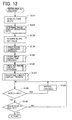
- Fig. 12 is a flowchart of an image display process program.
- the image display in Fig. 12 is processed. That is, at S121, first, the tape width of the print tape T is acquired. More specifically, as mentioned above, there are five types of tape width 24 mm, 18 mm, 12 mm, 9 mm, and 6 mm, and on the basis of the selective shielding by the photo couplers P1, P2, P3, by judging the combination of H signal and L signal issued from the tape width detector 13, the tape width of the print tape T is acquired. Going to S122, the reduction rate of the image display is determined on the basis of the acquired tape width.
- the reduction rate of the image display is determined on the basis of the table shown in Fig. 13 stored in the ROM 71.
- the content of the table shown in Fig. 13 is explained.
- the actual print height on the print label P is 128 dots
- 31% is determined as the reduction rate of image display
- 16% is determined as the reduction rate of image display.
- the actual print height on the print label P is 112 dots, and when the image display on the liquid crystal display 7 is displayed in the height of 40 dots, 36% is determined as the reduction rate of image display, and when the image display on the liquid crystal display 7 is displayed in the height of 20 dots, 18% is determined as the reduction rate of image display.
- the actual print height on the print label P is 70 dots, and when the image display on the liquid crystal display 7 is displayed in the height of 40 dots, 57% is determined as the reduction rate of image display, and when the image display on the liquid crystal display 7 is displayed in the height of 20 dots, 29% is determined as the reduction rate of image display.
- the actual print height on the print label P is 56 dots, and when the image display on the liquid crystal display 7 is displayed in the height of 40 dots, 71% is determined as the reduction rate of image display, and when the image display on the liquid crystal display 7 is displayed in the height of 20 dots, 36% is determined as the reduction rate of image display.
- the actual print height on the print label P is 32 dots, and when the image display on the liquid crystal display 7 is displayed in the height of 40 dots, 125% is determined as the reduction rate of image display (that is, the display is magnified), and when the image display on the liquid crystal display 7 is displayed in the height of 20 dots, 63% is determined as the reduction rate of image display.
- print image generation process at S124 print image reduction process at S125, reduced image display process at S126, and ruler and length display process at S127. These processes are described later.
- Fig. 14 is a flowchart of a print image generation process program.
- the print image generation in Fig. 14 is processed, first, at S141, generation of print image is processed.
- the dot pattern data stored in the development buffer is transferred to the image display buffer.
- the image data developed on the image display buffer is called "print image.”
- the position of the character corresponding to the beginning data of dot pattern on the image display buffer is specified. More specifically, if the dot pattern on the image display buffer is ABC, the position of the character A is specified.
- the position of the space ⁇ is specified in the case of the state of including space data in the beginning data of the text (see S111 in Fig. 9), or the position of the character A is specified in the case of the state of not including space data in the beginning data of the text (see S111 in Fig. 9).
- the process resumes the image display process program in Fig. 12.
- Fig. 15 is a flowchart of a print image reduction process program.
- the print image is reduced according to the reduction rate, and a reduced image is created.
- the reduction rate is the percentage determined already at S122 in Fig. 12.
- the image data of the print image reduced at the specified reduction rate is transferred to the image display buffer.
- the image data developed on the reduced image display buffer is called "reduced image.”
- the process resumes the image display process program in Fig. 12.
- Fig. 16 is a flowchart of a reduced image display process program.
- S161 the blank amount of the print label P in the reduced image is calculated, and at S162, it is judged whether the blank of the print label P is indicated or not.
- S163 the blank of the print label P in the reduced image is hatched, and the process goes to S164.
- the process goes to S164 without doing anything.
- the right side position of the character corresponding to the beginning data in the image display buffer is specified, and is multiplied by the reduction rate, and the right side position of the character corresponding to the beginning data in the reduced image display buffer is determined.
- the image data is moved so that the right side position of the character corresponding to the beginning data may coincide with the final position of the liquid crystal display 7, and, as a result, when the contour position corresponding to the leading end of the print label P is positioned right side of the beginning position of the liquid crystal display 7, it is judged that the extent from the beginning position of the liquid crystal display 7 to the contour position corresponding to the leading end of the print label P is a blank, and going to S166, the image is displayed on the liquid crystal display 7 on the basis of the reduced image display buffer.
- the dot pattern on the reduced image display buffer is ABC
- the right side position of the character A corresponding to the beginning data is moved to the final position of the liquid crystal display 7.
- the image of the print label P is displayed.
- the contour position S1 corresponding to the leading end of the print label P is positioned right side of the beginning position W1 of the liquid crystal display 7, the extent from the beginning position W1 of the liquid crystal display 7 to the contour position S1 corresponding to the leading end of the print label P is judged to be a blank.
- the dot pattern on the reduced image display buffer is ⁇ ABC (" ⁇ " means a space)
- the right side position of the space ⁇ corresponding to the beginning data is moved to the final position of the liquid crystal display 7 in the case of the state of including space data in the beginning data of the text (see S111 in Fig. 9).
- the right side position of the character A corresponding to the beginning data is moved to the final position of the liquid crystal display 7 in the case of the state of not including space data in the beginning data of the text (see S111 in Fig. 9).
- Fig. 18 is a flowchart of a ruler and length display process program.
- the ruler and length display in Fig. 18 is processed, first, going to S171, in the image display on the liquid crystal display 7, as shown in Fig. 20, for example, overall length L2 of the print label P is displayed in a second display region 104 in the unit of millimeters.
- the overall length L2 of the print label P is the value already calculated in the print image generation process in Fig. 14 and the value is used.
- S172 in the image display on the liquid crystal display 7, as shown in Fig.
- distance L1 from the leading end S1 of the print label P to the display start position S2 of the print label P is displayed in a first display region 103 in the unit of millimeters.
- the distance L1 from the leading end S1 of the print label P to the display start position S2 of the print label P is calculated on the basis of the position of the character corresponding to the beginning data specified at S142 of the print image generation process in Fig. 14.
- the lateral width of solid display region 102 provided in lengthy ruler 101 is calculated by the number of dots.
- the overall length of the print label P in the print image is 500 dots
- the distance from the initial position W1 of the liquid crystal display 7 in the reduced image to the final position W2 is 128 dots (see Fig. 17)
- the lateral length of the lengthy ruler 101 is 40 dots
- the calculation formula of 128 / 500 x 40 10 as the lateral width of the solid display region 102 provided in the lengthy ruler 101, 10 dots is obtained.
- the start position R1 of solid display region 102 provided in a lengthy ruler 101 is calculated by the number of dots.
- the overall length of the print label P in the print image is 500 dots
- the distance from the initial position W1 of the liquid crystal display 7 in the reduced image to the final position W2 is 128 dots (see Fig. 17)
- the lateral length of the lengthy ruler 101 is 40 dots
- the distance from the contour position S1 corresponding to the leading end of the print label P in the reduced image to the initial position W1 of the liquid crystal display 7 is X dots
- the start position R1 of the solid display region 102 is calculated by the number of dots.
- the lengthy ruler 101 is displayed in a white initial state, and at S176, in the lengthy ruler 101, from the start position R1 to the right side, a portion of 10 dots is hatched, and the solid display region 102 is displayed.
- the print key 3 when the print key 3 is entered, as one of other processes at S17 in Fig. 5, print process is executed, and the text is printed on the print tape T according to the content stored in the print buffer saved in the RAM 72, and then the print tape T is cut off automatically by cooperation of the fixed blade 56 and movable blade 57, and one print label P is produced.
- the image of the print label P can be displayed on the liquid crystal display 7 (S21 in Fig. 5).
- the lengthy ruler 101 corresponding to the overall contour of the print label P is provided, in the lengthy ruler 101, and by hatching the solid display region 102, the image display range of the print label P on the liquid crystal display 7 is displayed in a relative positional relation to the lengthy ruler 101 (S127 in Fig. 12).
- the right position of the character A corresponding to the beginning data of the text is moved to the position corresponding, to the final position W2 of the liquid crystal display 7, and in this state (S165 in Fig. 16), the image of the leading end portion of the print label P is displayed (S166 in Fig. 16), and, for example, as shown in Fig. 19 to Fig. 21, if a large blank is set at the leading end of the printing label P, as initial display state, it is possible to avoid the incidence of image display of only the blank at the leading end of the printing label P.
- the character and the like corresponding to the beginning data of the text to be printed on the print label P (for example, the character A in Fig. 19 to Fig. 21) is always displayed, and the image display range of the print label P can be instantly known, and the image display is easy to understand for the user.
- the text is, for example, ⁇ ABC (" ⁇ " being a space)
- ⁇ ABC space data
- the character and the like corresponding to the beginning data of the text to be printed on the print label P is always displayed, and the image display range of the print label P can be instantly known, and the image display is easy to understand for the user.
- the character and the like corresponding to the beginning data of the text to be printed on the print label P (for example, the character A in Fig. 19 to Fig. 21) is always displayed, and further at S112 in Fig. 9, by setting to indicate the blank positioned before and after the text to be printed on the print label P, for example, in Fig. 21, out of the forward blank positioned ahead of the text ABC, the image display portion 105 on the liquid crystal display 7 is displayed by hatching, and the blank can be clearly distinguished from the text, so that the image display is easy to understand for the user. This is the same when a space is present at the beginning of the text.
- the image display range of the print label P on the liquid crystal display 7 can be displayed in a relative positional relation with the lengthy ruler 101 (S127 in Fig. 12). Therefore, even if only the blank or space of the print label P is displayed, through the solid display region 102 in the lengthy ruler 101, the image display range of the print label P can be instantly known, and the image display is easy to understand for the user.
- the distance L1 from the leading end S1 of the print label P to the display start position S2 of the print label P is displayed in the first display region 103 in the unit of millimeters (S172 in Fig. 18), and the image display range of the print label P can be specifically known from the actual length of the distance from the leading end S1 of the print label P, so that the image display is easy to understand for the user.
- the distance L2 from the leading end S1 to the final end S3 of the print label P is displayed in the second display region 104 in the unit of millimeters (S171 in Fig. 18), and the actual length of the overall contour of the print label P can be specifically known, so that the image display is easy to understand for the user.
- the image of the print label P is displayed (S126 in Fig. 12) at the reduction rate (S121, S122 in Fig. 12) determined on the basis of the tape width of the print tape T, and the display range of the print label P can be scrolled (S129 in Fig. 12), so that the image display is easy to understand for the user.
- the text to be printed on the print label P is written horizontally, but it is similarly applicable to vertical writing.
- the tape printer 1 of the preferred embodiment in the image display of the liquid crystal display 7 (S21 in Fig. 5), for example, as shown in Figs. 17A, B, the right position of the character A corresponding to the beginning data of the text is moved to the position corresponding to the final position W2 of the liquid crystal display 7, and in this state (S165 in Fig. 16), the image of the leading end portion of the print label P is displayed (S166 in Fig. 16), and further as shown in Fig.
- the lengthy ruler 101 corresponding to the overall contour of the print label P is provided, and in this lengthy ruler 101, by the hatching solid display region 102, the image display range of the print label P on the liquid crystal display 7 is displayed in a relative positional relation with the lengthy ruler 101 (S127 in Fig. 12). In this respect, if only one of the two can be executed, its specific effect can be executed.
Landscapes
- Engineering & Computer Science (AREA)
- Theoretical Computer Science (AREA)
- Audiology, Speech & Language Pathology (AREA)
- Health & Medical Sciences (AREA)
- Computational Linguistics (AREA)
- General Health & Medical Sciences (AREA)
- Physics & Mathematics (AREA)
- General Engineering & Computer Science (AREA)
- General Physics & Mathematics (AREA)
- Artificial Intelligence (AREA)
- Printers Characterized By Their Purpose (AREA)
- Impression-Transfer Materials And Handling Thereof (AREA)
- Laminated Bodies (AREA)
- Organic Insulating Materials (AREA)
Abstract
Description
Claims (10)
- A tape printer (1) comprising text creating means (S18) for creating a text composed of document data such as characters, printing means (11) for printing the text on a lengthy print tape (T) in a state of having a forward blank positioned ahead of the text, cutting means (56, 57) for cutting off the print tape (T) having the text printed by the printing means (11) in a state of having the forward blank and a backward blank positioned behind the text, thereby producing a print label (P), and image display means (7) for displaying an image of the print label (P), further comprising:first display control means (S165) for displaying the image of a leading end portion of the print label (P) on the image display means (7) by disposing an image of beginning data of the text in a final position (W2) of the image display means (7).
- A tape printer (1) comprising text creating means (S18) for creating a text composed of document data such as characters, printing means (11) for printing the text on a lengthy print tape (T) in a state of having a forward blank positioned ahead of the text, cutting means (56, 57) for cutting off the print tape (T) having the text printed by the printing means (11) in a state of having the forward blank and a backward blank positioned behind the text, thereby producing a print label (P), and image display means (7) for displaying an image of the print label (P), further comprising:a lengthy display region (101) held in part of the image display means (7) to represent an overall contour of the print label (P); andsecond display control means (S127) for displaying a display range of the print label (P) in the image display means (7) in the display region (101) in a relative regional relation with the overall contour of the print label (P).
- A tape printer (1) comprising text creating means (S18) for creating a text composed of document data such as characters, printing means (11) for printing the text on a lengthy print tape (T) in a state of having a forward blank positioned ahead of the text, cutting means (56, 57) for cutting off the print tape (T) having the text printed by the printing means (11) in a state of having the forward blank and a backward blank positioned behind the text, thereby producing a print label (P), and image display means (7) for displaying an image of the print label (P), further comprising:first display control means (S165) for displaying an image of a leading end portion of the print label (P) on the image display means (7) by disposing an image of beginning data of the text in a final position (W2) of the image display means (7);a lengthy display region (101) held in part of the image display means (7) to represent an overall contour of the print label (P); andsecond display control means (S127) for displaying a display range of the print label (P) in the image display means (7) in the display region (101) in a relative regional relation with the overall contour of the print label (P).
- The tape printer (1) according to claim 1 or 3, further comprising:first setting means (S111) for setting whether or not to include space data in the beginning data of the text.
- The tape printer (1) according to claim 1, 3, or 4, further comprising:second setting means (S112) for setting whether or not to indicate the forward blank by the image display means (7).
- The tape printer (1) according to claim 2 or 3,
wherein the second display control means (S127) displays part of the print label (P) on the image display means (7) so that a display start position (S2) of the print label (P) is at a predetermined distance (L1) from a leading end (S1) of the print label (P). - The tape printer (1) according to claim 2, 3, or 6,
wherein the second display control means (S127) displays a distance (L2) of an overall length of the print label (P) on the image display means (7). - The tape printer (1) according to any one of claims 1 to 7, further comprising:wherein the second display control means (S21) determines a reduction rate on the basis of a detection result by the tape width detecting means (13), and displays the image of the print label (P) at the reduction rate.tape width detecting means (13) for detecting a tape width of the print tape (T),
- The tape printer (1) according to any one of claims 1 to 8, further comprising:instructing means (113) for instructing a move of a display range of the print label (P) in the image display means (7).
- The tape printer (1) according to claim 8,
wherein the second display control means (S21) determines the reduction rate also on the basis of an image display size of the print label (P).
Applications Claiming Priority (2)
| Application Number | Priority Date | Filing Date | Title |
|---|---|---|---|
| JP2004019827A JP4552444B2 (en) | 2004-01-28 | 2004-01-28 | Tape printer |
| JP2004019827 | 2004-01-28 |
Publications (2)
| Publication Number | Publication Date |
|---|---|
| EP1559565A1 true EP1559565A1 (en) | 2005-08-03 |
| EP1559565B1 EP1559565B1 (en) | 2007-09-26 |
Family
ID=34650785
Family Applications (1)
| Application Number | Title | Priority Date | Filing Date |
|---|---|---|---|
| EP04030299A Expired - Lifetime EP1559565B1 (en) | 2004-01-28 | 2004-12-21 | Tape printer |
Country Status (5)
| Country | Link |
|---|---|
| US (1) | US7252442B2 (en) |
| EP (1) | EP1559565B1 (en) |
| JP (1) | JP4552444B2 (en) |
| AT (1) | ATE374110T1 (en) |
| DE (1) | DE602004009148T2 (en) |
Families Citing this family (7)
| Publication number | Priority date | Publication date | Assignee | Title |
|---|---|---|---|---|
| JP2007334448A (en) * | 2006-06-12 | 2007-12-27 | Brother Ind Ltd | Tag label making device |
| JP4811282B2 (en) * | 2007-01-25 | 2011-11-09 | ブラザー工業株式会社 | Tape printing apparatus and tape printing program |
| JP5092614B2 (en) * | 2007-08-07 | 2012-12-05 | セイコーエプソン株式会社 | Tape printer and program |
| JP5240391B2 (en) * | 2012-09-11 | 2013-07-17 | セイコーエプソン株式会社 | Tape printer and program |
| JP2016175384A (en) * | 2015-03-23 | 2016-10-06 | セイコーエプソン株式会社 | Tape printer |
| JP6901342B2 (en) * | 2017-07-21 | 2021-07-14 | 東芝テック株式会社 | Information processing device |
| CN114055965B (en) | 2020-07-30 | 2026-01-02 | 兄弟工业株式会社 | Computer-readable storage media, printing apparatus and methods for creating printed labels |
Citations (5)
| Publication number | Priority date | Publication date | Assignee | Title |
|---|---|---|---|---|
| JPH03217860A (en) | 1990-01-23 | 1991-09-25 | Mitsubishi Paper Mills Ltd | Plate making method for planographic printing plate |
| JPH03217861A (en) | 1990-01-24 | 1991-09-25 | Tokyo Electric Co Ltd | Draining device for electrophotographic copying device |
| JPH06199002A (en) | 1992-12-28 | 1994-07-19 | Brother Ind Ltd | Tape printing machine |
| EP0656595A2 (en) * | 1993-12-01 | 1995-06-07 | Brother Kogyo Kabushiki Kaisha | Tape printing apparatus |
| EP0855282A2 (en) * | 1997-01-24 | 1998-07-29 | Esselte N.V. | Tape printing device |
Family Cites Families (8)
| Publication number | Priority date | Publication date | Assignee | Title |
|---|---|---|---|---|
| US4686649A (en) * | 1981-05-29 | 1987-08-11 | International Business Machines Corporation | Word processor with alternative formatted and unformatted display modes |
| JPH06227052A (en) * | 1993-02-04 | 1994-08-16 | Seiko Epson Corp | Tape printer |
| JPH07125374A (en) * | 1993-11-02 | 1995-05-16 | King Jim Co Ltd | Layout display device |
| JPH07156477A (en) * | 1993-12-02 | 1995-06-20 | Casio Comput Co Ltd | Printer |
| JP3377277B2 (en) * | 1994-01-19 | 2003-02-17 | ブラザー工業株式会社 | Document processing device |
| JPH0872322A (en) * | 1994-09-05 | 1996-03-19 | Brother Ind Ltd | Tape label making device |
| JP2916912B2 (en) * | 1997-07-25 | 1999-07-05 | セイコーエプソン株式会社 | Printing equipment |
| JP4624611B2 (en) * | 2001-09-06 | 2011-02-02 | セイコーエプソン株式会社 | CHARACTER INPUT DEVICE, TAPE PRINTING DEVICE HAVING THE SAME, AND CHARACTER INPUT METHOD FOR CHARACTER INPUT DEVICE |
-
2004
- 2004-01-28 JP JP2004019827A patent/JP4552444B2/en not_active Expired - Fee Related
- 2004-12-17 US US11/013,726 patent/US7252442B2/en not_active Expired - Lifetime
- 2004-12-21 EP EP04030299A patent/EP1559565B1/en not_active Expired - Lifetime
- 2004-12-21 AT AT04030299T patent/ATE374110T1/en not_active IP Right Cessation
- 2004-12-21 DE DE602004009148T patent/DE602004009148T2/en not_active Expired - Lifetime
Patent Citations (5)
| Publication number | Priority date | Publication date | Assignee | Title |
|---|---|---|---|---|
| JPH03217860A (en) | 1990-01-23 | 1991-09-25 | Mitsubishi Paper Mills Ltd | Plate making method for planographic printing plate |
| JPH03217861A (en) | 1990-01-24 | 1991-09-25 | Tokyo Electric Co Ltd | Draining device for electrophotographic copying device |
| JPH06199002A (en) | 1992-12-28 | 1994-07-19 | Brother Ind Ltd | Tape printing machine |
| EP0656595A2 (en) * | 1993-12-01 | 1995-06-07 | Brother Kogyo Kabushiki Kaisha | Tape printing apparatus |
| EP0855282A2 (en) * | 1997-01-24 | 1998-07-29 | Esselte N.V. | Tape printing device |
Also Published As
| Publication number | Publication date |
|---|---|
| US20050163551A1 (en) | 2005-07-28 |
| JP2005212196A (en) | 2005-08-11 |
| DE602004009148T2 (en) | 2008-01-17 |
| US7252442B2 (en) | 2007-08-07 |
| JP4552444B2 (en) | 2010-09-29 |
| DE602004009148D1 (en) | 2007-11-08 |
| ATE374110T1 (en) | 2007-10-15 |
| EP1559565B1 (en) | 2007-09-26 |
Similar Documents
| Publication | Publication Date | Title |
|---|---|---|
| US6585438B2 (en) | Tape printing apparatus and method, cutting device and method, and tape printing apparatus incorporating the cutting device | |
| US7357585B2 (en) | Printing tape, tape cartridge provided therewith, and tape printing apparatus | |
| JP5753415B2 (en) | Printing apparatus and printing apparatus control method | |
| JP3846035B2 (en) | Tape printer | |
| EP2142376A2 (en) | Tape printing apparatus and method with displaying features | |
| US7418667B2 (en) | Character input apparatus and tape printing apparatus incorporating the same as well as character input method | |
| US20070231043A1 (en) | Label-printing apparatus and label-printing program recorded on a computer readable recording medium | |
| JPH06199017A (en) | Tape printer | |
| EP1559565B1 (en) | Tape printer | |
| JP2012139952A (en) | Label forming device and control method for label forming device | |
| JP4423871B2 (en) | Printing apparatus, printing apparatus explanation posting method and program | |
| JP4404094B2 (en) | Printing apparatus and printing method | |
| US6821037B2 (en) | Printing device provided with cutter to cut recording paper | |
| JP2012139953A (en) | Label forming device and control method of label forming device | |
| US7625145B2 (en) | Data display method of data display apparatus, data display apparatus, data generation apparatus having the same, and sheet processing apparatus | |
| US20090056566A1 (en) | Tape Processing Apparatus and Method of Tape Processing | |
| JP4296968B2 (en) | Tape printer | |
| JP5552965B2 (en) | Tape printer and control method of tape printer | |
| JP5577950B2 (en) | Tape printer and control method of tape printer | |
| JP2560958B2 (en) | Tape printer | |
| JP3254653B2 (en) | Tape printer | |
| JP3864066B2 (en) | Tape printer | |
| JP3753573B2 (en) | Printing device and printing control method | |
| JP3731749B2 (en) | Tape printer | |
| JPH07195791A (en) | Tape printer |
Legal Events
| Date | Code | Title | Description |
|---|---|---|---|
| PUAI | Public reference made under article 153(3) epc to a published international application that has entered the european phase |
Free format text: ORIGINAL CODE: 0009012 |
|
| AK | Designated contracting states |
Kind code of ref document: A1 Designated state(s): AT BE BG CH CY CZ DE DK EE ES FI FR GB GR HU IE IS IT LI LT LU MC NL PL PT RO SE SI SK TR |
|
| AX | Request for extension of the european patent |
Extension state: AL BA HR LV MK YU |
|
| 17P | Request for examination filed |
Effective date: 20051005 |
|
| AKX | Designation fees paid |
Designated state(s): AT BE BG CH CY CZ DE DK EE ES FI FR GB GR HU IE IS IT LI LT LU MC NL PL PT RO SE SI SK TR |
|
| GRAP | Despatch of communication of intention to grant a patent |
Free format text: ORIGINAL CODE: EPIDOSNIGR1 |
|
| GRAS | Grant fee paid |
Free format text: ORIGINAL CODE: EPIDOSNIGR3 |
|
| GRAA | (expected) grant |
Free format text: ORIGINAL CODE: 0009210 |
|
| AK | Designated contracting states |
Kind code of ref document: B1 Designated state(s): AT BE BG CH CY CZ DE DK EE ES FI FR GB GR HU IE IS IT LI LT LU MC NL PL PT RO SE SI SK TR |
|
| REG | Reference to a national code |
Ref country code: GB Ref legal event code: FG4D |
|
| REG | Reference to a national code |
Ref country code: CH Ref legal event code: EP |
|
| REF | Corresponds to: |
Ref document number: 602004009148 Country of ref document: DE Date of ref document: 20071108 Kind code of ref document: P |
|
| REG | Reference to a national code |
Ref country code: IE Ref legal event code: FG4D |
|
| ET | Fr: translation filed | ||
| PG25 | Lapsed in a contracting state [announced via postgrant information from national office to epo] |
Ref country code: FI Free format text: LAPSE BECAUSE OF FAILURE TO SUBMIT A TRANSLATION OF THE DESCRIPTION OR TO PAY THE FEE WITHIN THE PRESCRIBED TIME-LIMIT Effective date: 20070926 Ref country code: LT Free format text: LAPSE BECAUSE OF FAILURE TO SUBMIT A TRANSLATION OF THE DESCRIPTION OR TO PAY THE FEE WITHIN THE PRESCRIBED TIME-LIMIT Effective date: 20070926 |
|
| PG25 | Lapsed in a contracting state [announced via postgrant information from national office to epo] |
Ref country code: AT Free format text: LAPSE BECAUSE OF FAILURE TO SUBMIT A TRANSLATION OF THE DESCRIPTION OR TO PAY THE FEE WITHIN THE PRESCRIBED TIME-LIMIT Effective date: 20070926 Ref country code: PL Free format text: LAPSE BECAUSE OF FAILURE TO SUBMIT A TRANSLATION OF THE DESCRIPTION OR TO PAY THE FEE WITHIN THE PRESCRIBED TIME-LIMIT Effective date: 20070926 |
|
| NLV1 | Nl: lapsed or annulled due to failure to fulfill the requirements of art. 29p and 29m of the patents act | ||
| PG25 | Lapsed in a contracting state [announced via postgrant information from national office to epo] |
Ref country code: BE Free format text: LAPSE BECAUSE OF FAILURE TO SUBMIT A TRANSLATION OF THE DESCRIPTION OR TO PAY THE FEE WITHIN THE PRESCRIBED TIME-LIMIT Effective date: 20070926 |
|
| REG | Reference to a national code |
Ref country code: CH Ref legal event code: PL |
|
| PG25 | Lapsed in a contracting state [announced via postgrant information from national office to epo] |
Ref country code: CH Free format text: LAPSE BECAUSE OF FAILURE TO SUBMIT A TRANSLATION OF THE DESCRIPTION OR TO PAY THE FEE WITHIN THE PRESCRIBED TIME-LIMIT Effective date: 20070926 Ref country code: ES Free format text: LAPSE BECAUSE OF FAILURE TO SUBMIT A TRANSLATION OF THE DESCRIPTION OR TO PAY THE FEE WITHIN THE PRESCRIBED TIME-LIMIT Effective date: 20080106 Ref country code: LI Free format text: LAPSE BECAUSE OF FAILURE TO SUBMIT A TRANSLATION OF THE DESCRIPTION OR TO PAY THE FEE WITHIN THE PRESCRIBED TIME-LIMIT Effective date: 20070926 Ref country code: GR Free format text: LAPSE BECAUSE OF FAILURE TO SUBMIT A TRANSLATION OF THE DESCRIPTION OR TO PAY THE FEE WITHIN THE PRESCRIBED TIME-LIMIT Effective date: 20071227 Ref country code: NL Free format text: LAPSE BECAUSE OF FAILURE TO SUBMIT A TRANSLATION OF THE DESCRIPTION OR TO PAY THE FEE WITHIN THE PRESCRIBED TIME-LIMIT Effective date: 20070926 |
|
| PG25 | Lapsed in a contracting state [announced via postgrant information from national office to epo] |
Ref country code: PT Free format text: LAPSE BECAUSE OF FAILURE TO SUBMIT A TRANSLATION OF THE DESCRIPTION OR TO PAY THE FEE WITHIN THE PRESCRIBED TIME-LIMIT Effective date: 20080226 Ref country code: IS Free format text: LAPSE BECAUSE OF FAILURE TO SUBMIT A TRANSLATION OF THE DESCRIPTION OR TO PAY THE FEE WITHIN THE PRESCRIBED TIME-LIMIT Effective date: 20080126 Ref country code: CZ Free format text: LAPSE BECAUSE OF FAILURE TO SUBMIT A TRANSLATION OF THE DESCRIPTION OR TO PAY THE FEE WITHIN THE PRESCRIBED TIME-LIMIT Effective date: 20070926 Ref country code: SK Free format text: LAPSE BECAUSE OF FAILURE TO SUBMIT A TRANSLATION OF THE DESCRIPTION OR TO PAY THE FEE WITHIN THE PRESCRIBED TIME-LIMIT Effective date: 20070926 |
|
| PG25 | Lapsed in a contracting state [announced via postgrant information from national office to epo] |
Ref country code: SE Free format text: LAPSE BECAUSE OF FAILURE TO SUBMIT A TRANSLATION OF THE DESCRIPTION OR TO PAY THE FEE WITHIN THE PRESCRIBED TIME-LIMIT Effective date: 20071226 Ref country code: RO Free format text: LAPSE BECAUSE OF FAILURE TO SUBMIT A TRANSLATION OF THE DESCRIPTION OR TO PAY THE FEE WITHIN THE PRESCRIBED TIME-LIMIT Effective date: 20070926 |
|
| PG25 | Lapsed in a contracting state [announced via postgrant information from national office to epo] |
Ref country code: MC Free format text: LAPSE BECAUSE OF NON-PAYMENT OF DUE FEES Effective date: 20071231 Ref country code: DK Free format text: LAPSE BECAUSE OF FAILURE TO SUBMIT A TRANSLATION OF THE DESCRIPTION OR TO PAY THE FEE WITHIN THE PRESCRIBED TIME-LIMIT Effective date: 20070926 |
|
| PLBE | No opposition filed within time limit |
Free format text: ORIGINAL CODE: 0009261 |
|
| STAA | Information on the status of an ep patent application or granted ep patent |
Free format text: STATUS: NO OPPOSITION FILED WITHIN TIME LIMIT |
|
| 26N | No opposition filed |
Effective date: 20080627 |
|
| PG25 | Lapsed in a contracting state [announced via postgrant information from national office to epo] |
Ref country code: IE Free format text: LAPSE BECAUSE OF NON-PAYMENT OF DUE FEES Effective date: 20071221 |
|
| PG25 | Lapsed in a contracting state [announced via postgrant information from national office to epo] |
Ref country code: EE Free format text: LAPSE BECAUSE OF FAILURE TO SUBMIT A TRANSLATION OF THE DESCRIPTION OR TO PAY THE FEE WITHIN THE PRESCRIBED TIME-LIMIT Effective date: 20070926 |
|
| PG25 | Lapsed in a contracting state [announced via postgrant information from national office to epo] |
Ref country code: SI Free format text: LAPSE BECAUSE OF FAILURE TO SUBMIT A TRANSLATION OF THE DESCRIPTION OR TO PAY THE FEE WITHIN THE PRESCRIBED TIME-LIMIT Effective date: 20070926 |
|
| PG25 | Lapsed in a contracting state [announced via postgrant information from national office to epo] |
Ref country code: CY Free format text: LAPSE BECAUSE OF FAILURE TO SUBMIT A TRANSLATION OF THE DESCRIPTION OR TO PAY THE FEE WITHIN THE PRESCRIBED TIME-LIMIT Effective date: 20070926 |
|
| PG25 | Lapsed in a contracting state [announced via postgrant information from national office to epo] |
Ref country code: LU Free format text: LAPSE BECAUSE OF NON-PAYMENT OF DUE FEES Effective date: 20071221 Ref country code: BG Free format text: LAPSE BECAUSE OF FAILURE TO SUBMIT A TRANSLATION OF THE DESCRIPTION OR TO PAY THE FEE WITHIN THE PRESCRIBED TIME-LIMIT Effective date: 20071226 |
|
| PG25 | Lapsed in a contracting state [announced via postgrant information from national office to epo] |
Ref country code: HU Free format text: LAPSE BECAUSE OF FAILURE TO SUBMIT A TRANSLATION OF THE DESCRIPTION OR TO PAY THE FEE WITHIN THE PRESCRIBED TIME-LIMIT Effective date: 20080327 Ref country code: TR Free format text: LAPSE BECAUSE OF FAILURE TO SUBMIT A TRANSLATION OF THE DESCRIPTION OR TO PAY THE FEE WITHIN THE PRESCRIBED TIME-LIMIT Effective date: 20070926 |
|
| PG25 | Lapsed in a contracting state [announced via postgrant information from national office to epo] |
Ref country code: IT Free format text: LAPSE BECAUSE OF NON-PAYMENT OF DUE FEES Effective date: 20071231 |
|
| REG | Reference to a national code |
Ref country code: FR Ref legal event code: PLFP Year of fee payment: 12 |
|
| REG | Reference to a national code |
Ref country code: FR Ref legal event code: PLFP Year of fee payment: 13 |
|
| REG | Reference to a national code |
Ref country code: FR Ref legal event code: PLFP Year of fee payment: 14 |
|
| PGFP | Annual fee paid to national office [announced via postgrant information from national office to epo] |
Ref country code: GB Payment date: 20221109 Year of fee payment: 19 Ref country code: FR Payment date: 20221110 Year of fee payment: 19 Ref country code: DE Payment date: 20221109 Year of fee payment: 19 |
|
| REG | Reference to a national code |
Ref country code: DE Ref legal event code: R119 Ref document number: 602004009148 Country of ref document: DE |
|
| GBPC | Gb: european patent ceased through non-payment of renewal fee |
Effective date: 20231221 |
|
| PG25 | Lapsed in a contracting state [announced via postgrant information from national office to epo] |
Ref country code: DE Free format text: LAPSE BECAUSE OF NON-PAYMENT OF DUE FEES Effective date: 20240702 |
|
| PG25 | Lapsed in a contracting state [announced via postgrant information from national office to epo] |
Ref country code: GB Free format text: LAPSE BECAUSE OF NON-PAYMENT OF DUE FEES Effective date: 20231221 |
|
| PG25 | Lapsed in a contracting state [announced via postgrant information from national office to epo] |
Ref country code: FR Free format text: LAPSE BECAUSE OF NON-PAYMENT OF DUE FEES Effective date: 20231231 |
|
| PG25 | Lapsed in a contracting state [announced via postgrant information from national office to epo] |
Ref country code: GB Free format text: LAPSE BECAUSE OF NON-PAYMENT OF DUE FEES Effective date: 20231221 Ref country code: FR Free format text: LAPSE BECAUSE OF NON-PAYMENT OF DUE FEES Effective date: 20231231 Ref country code: DE Free format text: LAPSE BECAUSE OF NON-PAYMENT OF DUE FEES Effective date: 20240702 |