EP1559456B1 - skibindung mit integrierter auslösung - Google Patents
skibindung mit integrierter auslösung Download PDFInfo
- Publication number
- EP1559456B1 EP1559456B1 EP04030543A EP04030543A EP1559456B1 EP 1559456 B1 EP1559456 B1 EP 1559456B1 EP 04030543 A EP04030543 A EP 04030543A EP 04030543 A EP04030543 A EP 04030543A EP 1559456 B1 EP1559456 B1 EP 1559456B1
- Authority
- EP
- European Patent Office
- Prior art keywords
- latch
- return
- boot
- binding device
- binding
- Prior art date
- Legal status (The legal status is an assumption and is not a legal conclusion. Google has not performed a legal analysis and makes no representation as to the accuracy of the status listed.)
- Expired - Lifetime
Links
- 230000027455 binding Effects 0.000 claims description 21
- 238000009739 binding Methods 0.000 claims description 21
- 238000004873 anchoring Methods 0.000 claims description 7
- 230000006835 compression Effects 0.000 description 3
- 238000007906 compression Methods 0.000 description 3
- 238000006073 displacement reaction Methods 0.000 description 3
- 230000000694 effects Effects 0.000 description 3
- 230000000295 complement effect Effects 0.000 description 2
- 239000000835 fiber Substances 0.000 description 2
- 241001080024 Telles Species 0.000 description 1
- 229920006231 aramid fiber Polymers 0.000 description 1
- 238000010276 construction Methods 0.000 description 1
- 230000007423 decrease Effects 0.000 description 1
- 230000009189 diving Effects 0.000 description 1
- 239000000463 material Substances 0.000 description 1
- 239000002184 metal Substances 0.000 description 1
Images
Classifications
-
- A—HUMAN NECESSITIES
- A63—SPORTS; GAMES; AMUSEMENTS
- A63C—SKATES; SKIS; ROLLER SKATES; DESIGN OR LAYOUT OF COURTS, RINKS OR THE LIKE
- A63C9/00—Ski bindings
- A63C9/20—Non-self-releasing bindings with special sole edge holders instead of toe-straps
Definitions
- the invention relates to a device for attaching a shoe to a sports article.
- the invention can be applied in particular to devices for attaching a boot to a ski. It can be used in particular for the design of cross-country ski bindings, alpine ski mountaineering, Nordic ski touring or Telemark skiing. It can also be used for the design of bindings of ice skates, roller skates or snowshoes.
- the principle of these devices is to allow a fixation of the boot on the ski which is perfectly rigid in torsion but which allows a free lifting of the heel of the shoe.
- the device described in the document WO00 / 13755 is an improvement of the attachment systems currently used for example in cross-country skiing or ski touring in which the shoe is articulated by its front end about a transverse axis relative to the ski. Indeed, the movement of the foot relative to the ski, during the lifting of the heel, is a movement that is no longer a simple rotation and is as close as possible to the natural movement of unfolding of the foot.
- the invention may also be implemented in the context of a fixing device of the type described in the document WO96 / 37269 , EP-1106218 or 1364685 .
- the shoe is no longer attached to the sports article by one or more fixed points, but it is hooked (and secured) to a connecting member which can move relative to the 'sport item.
- This displacement can be a simple rotation but, in the examples cited above, it is rather a complex displacement mixing several rotational movements and / or translation.
- these types of fasteners may comprise elastic return means that return the connecting member to its lower position which corresponds to the position it occupies when the shoe to which it is attached is in support of the front and back on the ski.
- elastic return means will for example be very useful when the fixing device is intended for the practice of cross-country skiing, ice skating, roller skating.
- the catching and unhooking mechanism must therefore be simple, reliable and lightweight, and it must include a minimum of parts to remain compact and inexpensive to produce.
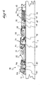
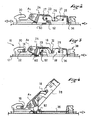
- the fixing device 10 illustrated on the figures 1 and 2 comprises a base 12 which is intended to be fixed on a sports article 11, but which could also be directly integrated in the latter.
- the base 12 could also be made of several parts, some or not of these parts being integrated in the sport article 11.
- the device is intended to ensure the attachment of a shoe having two connecting areas.
- the shoe comprises two anchoring members 16, 18 which are arranged in the sole of the boot so as to be flush with it below.
- Anchoring members 16, 18 of this type are described in the patent applications EP-A-913102 and EP-A-913103 which will be usefully referred to for more details.
- EP-A-913102 and EP-A-913103 which will be usefully referred to for more details.
- it is here two cylindrical bars of revolution arranged across a longitudinal groove in the underside of the sole. For the clarity of the drawings, only the bars 16, 18 are illustrated on the Figures 3 and 4 .
- the front bar 16 is for example located in the vicinity of the front end of the sole and the rear bar 18 is shifted rearwardly by a distance defined to be arranged at or in front of an area of the corresponding shoe to the metatarsophalangeal flexion zone of the user's foot.
- This arrangement of the binding areas is particularly appreciated in cross-country skiing because it allows, with a soft sole shoe, to maintain a flexion of the shoe corresponding to that of the foot.
- the invention could be implemented with anchoring members having another geometry. Each of the connecting members is therefore, with the corresponding portion of the sole, an embodiment of a binding zone of the shoe.
- the fastening device comprises firstly, at the front of the base 12, a fixed hook 20 which delimits a groove 22 open longitudinally towards the rear, and which is intended to receive the front cylindrical bar 16 of the shoe.
- the groove 22 has a height which is substantially identical to or slightly greater than the diameter of the front bar 16 so that the front bar is received in the groove with a minimum of play in the vertical direction.
- the groove 22 has a profile which is elongated along a rectilinear path.
- the groove 22 could also have a curved profile plunging forward and downward.
- the hook 20 is arranged above the upper face of the base 12. This hook is intended to be received in the longitudinal groove of the sole of the shoe so that, by cooperation of shapes, it participates in guiding the shoe in translation in a transverse direction (perpendicular to the plane of the figures) and in rotation along a vertical axis. In this way, the hook 20 has substantially the same width as the corresponding section of the groove of the boot, and the groove 22 is open transversely in the two lateral faces of the hook 20.
- the fixing device 10 comprises a hooking arm 24 of fixed length which is articulated at two fixed points on the one hand on the base 12 and on the other hand on the second connection zone of the shoe, namely in this case the rear bar 18.
- the arm 24, which forms a connecting member on which the shoe is attached, is articulated on the base 12, at its front end, about a transverse axis A1 which is arranged behind the hook 20. It is thus likely to move relative to the sports article between a low position (illustrated in FIGS. Figures 1 to 3 ) and a high position (shown in figure 4 ).
- the attachment arm 24 also has, on its rear part, a latch 28 which is provided to lock the rear cylindrical bar 18 of the boot.
- the attachment arm 24 comprises a fixed jaw which consists of a groove 26 open upwards, and a sliding mobile jaw, the latch 28, which is movable between a rearward opening position ( figures 1 and 2 ) and a pre-closing position illustrated on the figures 3 and 4 .
- the two jaws In this closed position, the two jaws define a housing of section corresponding to that of the rear bar 18 of the shoe.
- the bar 18 is then trapped and locked in the housing closed by the latch 28, while allowing a relative rotational movement of the bar 18 relative to the latching arm 24, about the axis of the cylindrical bar 18.
- the attachment arm is preferably also received in the groove of the sole and its dimensions are preferably provided so that the arm also participates in the transverse guidance of the shoe.
- the attachment arm In its low position illustrated at figure 1 at rest, the attachment arm is oriented substantially horizontally. In this position, it is possible to hang the shoe very simply on the device. For this, simply engage the front bar 16 of the shoe in the groove 22, then by rotation around the front bar, to lower the shoe to come lock the rear bar 18 on the hook arm 24.
- the latch 28 which receives the rear bar of the boot is arranged behind the axis A1 of articulation of the arm 24 on the device 10.
- the rear bar of the shoe describes, when the user raises the heel of the shoe relative to the sports article, an arcuate trajectory about the axis A1 of articulation arm 24 on the base. Indeed, once the rear bar 18 locked on the arm 24, it remains at a constant distance from the axis A1. During this perfectly determined movement of the rear bar 18, that is to say of an area of the shoe that corresponds substantially to the metatarsophalangeal articulation of the user's foot, the front bar 16 is free longitudinally and moves in the groove 22, in this case towards the front thereof.
- this front bar While moving longitudinally, this front bar is perfectly guided along a path defined by the profile of the groove 22.
- the groove 22 controls a downward movement of the front bar 16 when the heel of the shoe rise up. This diving movement is particularly sensitive at the end of the movement.
- the overall kinematics of the device is therefore mainly given by the locking arm 24, but it is also influenced by the geometry of the guide groove 22. This may have a profile different from that illustrated here.
- the fastening device 10 also comprises an elastic return system of the attachment arm 24 to its lower position.
- the elastic return system comprises at least one elastic member 34 which is connected to the sport article 11, and a flexible link 36 which connects the elastic member 34 to the arm hooking 24 and which cooperates with at least one return member 52, which will be seen later that it is mounted on the base 12 mobile.
- the fastening device 10 comprises a guide edge 38 which is formed of a section of parallelepipedal section and extends longitudinally rearwardly behind the hook arm 24.
- this guide edge 38 is provided to cooperate with the complementary section groove arranged in the sole of the shoe to ensure lateral guidance of the shoe / fastening assembly.
- This guide edge 38 therefore extends the hook 20 and the attachment arm 24 rearwardly.
- the elastic member 34 is integrated inside a housing 40 formed inside this edge 38.
- the elastic member 34 is a compression spring which is arranged horizontally and longitudinally in the housing 40. The front end of the spring 34 bears against a front face 42 of the housing 40. This front end of the spring is therefore fixed.
- the rear end of the spring bears against a movable carriage 44 which can slide longitudinally relative to the base 12 and to the edge 38. More specifically, the carriage 44 has a front end 46 which moves at the level of a front opening 48 of the housing 40, and a rear end 50 which moves in the housing 40 and on which the rear end of the spring 34 is based.
- Such an arrangement of an elastic member and a movable carriage is similar to that found in the device described in the document EP-768 103 and in some of the cross-country ski binding devices marketed by the Applicant.
- the device shown here comprises a flexible link 36 which connects the elastic member 34 to the latching arm 24.
- the link 36 is not hooked directly on the elastic member 34 but on the front end 46 of the carriage 44. It passes on a return 52 which is constituted by a single rod mounted on a slide 60 which is slidable longitudinally on the base 12.
- the return 52 could also consist of a pulley or other sliding surface, preferably curved.
- the flexible link is substantially inextensible. It may for example be a wire rope or a fiber cable with very low extensibility, for example an aramid fiber cable. It can also be envisaged that this link is made in the form of a band. This traction band may for example be made in the form of a metal strip, a single braided son strip, or a bundle of parallel fibers embedded in a polymeric material. Preferably, the link is sufficiently flexible and flexible not to provide a noticeable elastic effect, and especially to support an angle of about 90 degrees.
- the other end of the flexible link 36 is hooked on the latching arm 24, more precisely on the latch 28 carried by the arm 24.
- the latch is in this case a part which is slidably mounted on the arm 24, between an open retracted position (illustrated to the figures 1 and 2 ) and a closed forward position (shown in Figures 3 and 4 ).
- the latch 28 comprises two guide bars, front 23 and rear 25, which slide in complementary guide holes 27 arranged in the arm 24.
- the profile of these lights 27 determines the stroke of the latch 28 between its open positions and closed.
- the invention could also be implemented with a pivoting latch, or more generally with any lock capable of passing from an open state to a closed state.
- the flexible link 36 pulls the movable carriage 44 forwards and causes the compression of the spring 34, which thus provides a return force which tends to bring the shoe to a horizontal position with respect to the sports article.
- the flexible link is part of the return system of the connecting member to its lower position.
- the device according to the invention could also comprise a stop system in the end race (not shown), elastic or not, for example made in the form of a buffer arranged at the front end of the device, and intended to cooperate with a front support face of the sole.
- the flexible link is also used to determine the relative position of the lock 28 relative to the pivoting arm 24.
- the device comprises means for controlling the return 52 between a retracted position illustrated in FIGS. figures 1 and 2 , and an advanced position illustrated to Figures 3 and 4 this by a longitudinal displacement of the slide 60 at the rear end of which the return is arranged.
- the drawer has, at its front end, a lug 62 which is received in an eccentric groove 63 arranged in the underside of a control knob 64 rotatably mounted at the front end of the base 12 around a A2 vertical axis. Any other control device for moving the drawer and / or the return is of course conceivable.
- link 36 is attached to the latch 28 via its front guide bar 25.
- the latch 28 has an inclined ramp 32 which is arranged such that, when the latch 28 is closed position (in the absence of shoes), it is sufficient that the bar 18 exerts on the ramp 32 a substantially vertical force, from top to bottom, to push the latch 28 to its open position in which it allows access to the groove 26. This is of course when the latch 28 is initially in the closed position, and the decline of lock is against the elastic return force exerted on the lock by the link 36 and the spring 34. Also, when the bar 18 has entered the groove 26, these return means 34, 36 automatically return the latch 28 in its closed position. In this way, we see that the device according to the invention allows a footing type "step-in" where the lock is done automatically, without action of the user on the control button.
- the locking force imposed on the lock by the flexible link is related to the tension force imposed on the flexible link by the elastic member 34. Now the pivoting arm 24 is raised upwards, more the tension force is high, which only reinforces the locking force. In this way, the locking provided by the device of the invention is particularly reliable.
- the device comprises a mechanism for adjusting the stiffness of the elastic member 34.
- the point of attachment on the latch is preferably arranged such that the portion of the flexible link 36 which extends between the return 52 and the latching arm 24 is substantially vertical, so that the return force applied to the latching arm 24 is mainly directed downwards, including when the latter is in the up position as illustrated in FIG. figure 3 .
- the reference and the latch 28 are arranged near the metatarsophalangeal articulation zone of the user's foot when the shoe is fixed on the device. In this way, the return force exerted on the connecting member 24 is oriented in a direction close to that of the trajectory of the pivoting arm between its high and low positions, this for an optimal efficiency of the return effect.
- the part of the link 36 that goes from the reference 52 to the elastic member 34 extends in a substantially horizontal direction, directly in the sliding direction of the carriage 44 and compression of the spring 34.
- the unlocking of the device requires the user to return the connecting member 24 in the low position, then to actuate the control knob 64 to back the return 52 so as to cause the opening of the latch 28, the energy opening of the opening being provided by the elastic member 34.
- the release of the rear bar 18 is first allowed vertically upward, and in a second step the release of the front bar 16, longitudinally backwards and / or upwards.
- the invention thus makes it possible to obtain a locking / unlocking device whose construction is relatively simple and which makes it possible to ensure perfectly reliable locking and unlocking of the boot.
- This device is likely to be integrated with many types of fasteners.
- the invention can be integrated with fastening devices whose connecting member has a convex surface which bears on the sports article, and / or whose binding member is linked to the article. of sport by a mechanism comprising at least one link.
- the invention applies both in the case of a device comprising an articulated latch and in the case of a device in which the latch is sliding.
- the device comprises a mechanism for adjusting the stiffness of the elastic member.
Landscapes
- Footwear And Its Accessory, Manufacturing Method And Apparatuses (AREA)
- Battery Mounting, Suspending (AREA)
- Cash Registers Or Receiving Machines (AREA)
- Fittings On The Vehicle Exterior For Carrying Loads, And Devices For Holding Or Mounting Articles (AREA)
- Lock And Its Accessories (AREA)
- Telephone Function (AREA)
Claims (15)
- Vorrichtung zur Befestigung eines Schuhs auf einem Ski, einer Kufe oder einem Schneeschuh, einen Riegel (28) umfassend, welcher beweglich zwischen einer offenen und geschlossenen Stellung ist, in welchem der Riegel mit einem Verankerungsorgan (18) zusammenwirkt, welches mit dem Ski verbunden ist, um die Befestigung des Schuhs auf der Vorrichtung zu gewährleisten, dadurch gekennzeichnet, dass die Vorrichtung zumindest umfasst:eine weiche Verbindung (36), unter Spannung gehalten, welche mit der Verriegelung (28) verbunden ist und welche mit zumindest einer Rückstellung (52) zusammenwirkt, welche beweglich auf der Vorrichtung befestigt ist;einen Steuermechanismus (60, 62, 64) der Rückstellung (52) zwischen zwei Öffnungs- und Schließstellungen in der Weise, dass, in Abhängigkeit der Rückstellstellung die weiche Verbindung (36) das Verschieben der Verriegelung (28) zu ihrer offenen Position oder ihrer geschlossenen Position hervorruft.
- Befestigungsvorrichtung nach Anspruch 1, dadurch gekennzeichnet, dass die weiche Verbindung (36) durch ein elastisches Organ (34) unter Spannung gehalten wird.
- Vorrichtung zur Befestigung nach Anspruch 2, dadurch gekennzeichnet, dass die weiche Verbindung (36) an dem Sportartikel durch das Zwischenmittel des elastischen Organs (34) verbunden ist.
- Vorrichtung zur Befestigung eines Schuhs auf einem Sportartikel nach Anspruch 3, dadurch gekennzeichnet, dass sie ein Verbindungsorgan (24) mit dem Schuh umfasst, welches geeignet ist, sich in Bezug auf den Sportartikel zwischen einer unteren und einer oberen Position zu verschieben, so dass die Verriegelung (28) mit dem Verbindungsorgan (24) fest verbunden ist, und dass das elastische Steuerorgan (34) der Verriegelung (28) die elastische Rückstellung des Verbindungsorgans (24) zu seiner unteren Stellung gewährleistet.
- Befestigungsvorrichtung nach Anspruch 4, dadurch gekennzeichnet, dass der Schuh ein erstes Verankerungsorgan (16) umfasst, welches am Vorderteil des Schuhs angeordnet ist, und ein zweites Verankerungsorgan (18) umfasst, welches sich hinter dem ersten befindet, und dadurch, dass das Verbindungsorgan (24) von fester Länge ist, und gelenkig an zwei Punkten einerseits auf einem Sockel (12, A1), der mit dem Sportartikel (11) verbunden ist, und andererseits durch die Verriegelung (28) auf dem zweiten Verankerungsorgan (18) des Schuhs verbunden ist.
- Befestigungsvorrichtung nach Anspruch 4, dadurch gekennzeichnet, dass das Verbindungsorgan eine konvexe Oberfläche umfasst, welche auf dem Sportartikel aufliegt.
- Befestigungsvorrichtung nach einem der Anspruche 4 oder 5, dadurch gekennzeichnet, dass das Verbindungsorgan mit dem Sportartikel durch einen Mechanismus verbunden ist, welcher zumindest ein Schaltgestänge umfasst.
- Befestigungsvorrichtung nach einem der vorhergehenden Ansprüche, dadurch gekennzeichnet, dass die Veränderung der Rückstellung eine Veränderung des Winkels zwischen der Ausrichtung des weichen Verbindungsteils einerseits, welches sich zwischen der Rückstellung und der Verriegelung ausdehnt, und andererseits der Ausrichtung der Trajektorie der Verriegelung (28) zwischen ihren offenen und geschlossenen Stellungen hervorruft.
- Befestigungsvorrichtung nach irgendeinem der vorhergehenden Ansprüche, dadurch gekennzeichnet, dass die Verriegelung (28) gleitend ist.
- Befestigungsvorrichtung nach irgendeinem der Ansprüche 1 bis 8, dadurch gekennzeichnet, dass die Verriegelung gelenkig ist.
- Befestigungsvorrichtung nach irgendeinem der der vorhergehenden Ansprüche, dadurch gekennzeichnet, dass die Rückstellung eine Rolle umfasst.
- Befestigungsvorrichtung nach irgendeinem der Ansprüche 1 bis 10, dadurch gekennzeichnet, dass die Rückstellung zumindest eine gekrümmte Gleitoberfläche (52) umfasst, auf welcher die weiche Verbindung aufliegt und gleitet.
- Befestigungsvorrichtung nach Anspruch 4, dadurch gekennzeichnet, dass sie zusätzlich zu dem elastischen Rückstellsystem, welches von der weichen Verbindung und dem elastischen Organ gebildet wird, einen festen oder elastischen Anschlag umfasst, welcher am Ende des Verlaufs des Schuhs wirkt.
- Befestigungsvorrichtung nach irgendeinem der vorhergehenden Ansprüche, dadurch gekennzeichnet, dass sie einen Regelungsmechanismus des elastischen Organs (34) umfasst.
- Befestigungsvorrichtung nach irgendeinem der vorhergehenden Ansprüche, dadurch gekennzeichnet, dass sich die Verriegelung (28) in der Nähe der Mittelfußzehenknochenbiegungszone des Fußes des Benutzers befindet, wenn der Schuh auf der Vorrichtung befestigt ist.
Applications Claiming Priority (2)
| Application Number | Priority Date | Filing Date | Title |
|---|---|---|---|
| FR0400897A FR2865660B1 (fr) | 2004-01-30 | 2004-01-30 | Dispositif de fixation a deverrouillage integre |
| FR0400897 | 2004-01-30 |
Publications (2)
| Publication Number | Publication Date |
|---|---|
| EP1559456A1 EP1559456A1 (de) | 2005-08-03 |
| EP1559456B1 true EP1559456B1 (de) | 2008-09-24 |
Family
ID=34639811
Family Applications (1)
| Application Number | Title | Priority Date | Filing Date |
|---|---|---|---|
| EP04030543A Expired - Lifetime EP1559456B1 (de) | 2004-01-30 | 2004-12-23 | skibindung mit integrierter auslösung |
Country Status (5)
| Country | Link |
|---|---|
| EP (1) | EP1559456B1 (de) |
| AT (1) | ATE409073T1 (de) |
| DE (1) | DE602004016723D1 (de) |
| FR (1) | FR2865660B1 (de) |
| NO (1) | NO327569B1 (de) |
Families Citing this family (1)
| Publication number | Priority date | Publication date | Assignee | Title |
|---|---|---|---|---|
| AT519525B1 (de) | 2016-12-19 | 2019-01-15 | Fischer Sports Gmbh | Langlauf- oder Tourenskibindung |
Family Cites Families (12)
| Publication number | Priority date | Publication date | Assignee | Title |
|---|---|---|---|---|
| FR2770096B1 (fr) | 1997-10-29 | 1999-12-17 | Salomon Sa | Semelle de chaussure de sport |
| US5669622A (en) * | 1995-02-08 | 1997-09-23 | Miller; Michael E. | Ski binding |
| AU695197B2 (en) | 1995-05-24 | 1998-08-06 | Gierveld Beheer B.V. | Sport device |
| DE29824950U1 (de) | 1997-07-07 | 2003-09-11 | Fritschi Ag Swiss Bindings, Reichenbach Im Kandertal | Skibindung |
| WO1999002226A1 (en) * | 1997-07-11 | 1999-01-21 | Harold Edward Ayliffe | Pre-compressed spring ski binding |
| FR2770097B3 (fr) | 1997-10-29 | 2000-01-07 | Salomon Sa | Semelle de chaussure de sport |
| FR2782652B1 (fr) | 1998-09-02 | 2000-10-06 | Salomon Sa | Dispositif de fixation d'une chaussure a un article de sport |
| FR2801802B1 (fr) | 1999-12-06 | 2002-06-21 | Rossignol Sa | Fixation de ski de fond |
| WO2001093963A1 (de) | 2000-06-08 | 2001-12-13 | Rottefella As | Anordnung aus einer skibindung und einem skischuh |
| FR2850031B1 (fr) * | 2003-01-21 | 2006-08-11 | Salomon Sa | Fixation a energie deportee |
| EP1364685A1 (de) | 2003-05-20 | 2003-11-26 | Fritschi AG - Swiss Bindings | Skibindung |
| JP2006211296A (ja) | 2005-01-28 | 2006-08-10 | Sony Corp | マイクロマシンの製造方法およびマイクロマシン |
-
2004
- 2004-01-30 FR FR0400897A patent/FR2865660B1/fr not_active Expired - Fee Related
- 2004-12-23 DE DE602004016723T patent/DE602004016723D1/de not_active Expired - Lifetime
- 2004-12-23 EP EP04030543A patent/EP1559456B1/de not_active Expired - Lifetime
- 2004-12-23 AT AT04030543T patent/ATE409073T1/de not_active IP Right Cessation
-
2005
- 2005-01-31 NO NO20050559A patent/NO327569B1/no not_active IP Right Cessation
Also Published As
| Publication number | Publication date |
|---|---|
| EP1559456A1 (de) | 2005-08-03 |
| FR2865660B1 (fr) | 2006-04-07 |
| ATE409073T1 (de) | 2008-10-15 |
| DE602004016723D1 (de) | 2008-11-06 |
| FR2865660A1 (fr) | 2005-08-05 |
| NO327569B1 (no) | 2009-08-17 |
| NO20050559D0 (no) | 2005-01-31 |
| NO20050559L (no) | 2005-08-01 |
Similar Documents
| Publication | Publication Date | Title |
|---|---|---|
| EP1488831B1 (de) | Bindung mit einem Schwenkarm | |
| EP1839713B1 (de) | Einheit aus einem Langlaufski und einer Langlaufbindung | |
| EP1440713B1 (de) | Bindung mit versetzter Energie | |
| EP0925098A1 (de) | Bindungsvorrichtung zur befestigung eines schuhes an einem sportartikel | |
| FR2882658A1 (fr) | Dispositif de fixation a double commande | |
| EP1616604A1 (de) | Bindungsanlage für einen Schuh an einem Sportgerät mit getrennten elastischen Rückstellmitteln | |
| EP1312397B1 (de) | Vorrichtung zum Fixieren eines Schuhs an einen Sportartikel | |
| EP1104251A1 (de) | Langlaufskischuh | |
| EP1526900A2 (de) | Bindung mit integrierten einhaksystem | |
| FR2865660A1 (fr) | Dispositif de fixation a deverrouillage integre | |
| EP3741436B1 (de) | Bindungsvorrichtung zur befestigung eines snowboardschuhs auf einem snowboard | |
| EP1721641B1 (de) | Bindungsvorrichtung mit einstellbarer Rückhubenergie | |
| EP0231713B1 (de) | Kombination bestehend aus einem Langlaufski, einer Langlaufbindung und einem Langlaufschuh | |
| EP1785172B1 (de) | Sportschuh-Bindungsvorrichtung auf einem Gleitbrett | |
| FR2853253A1 (fr) | Fixation avec un organe de liaison en deux parties | |
| FR2843310A1 (fr) | Dispositif de fixation a decrochage par l'avant | |
| EP2322255A1 (de) | Bremsvorrichtung für Snowboard | |
| EP1319424A1 (de) | Bindungsanlage für ein Schuh an ein Sportgerät ohne Hebung | |
| FR2824747A1 (fr) | Systeme de fixation a tirant avec blocage en position ouverte | |
| WO1998016283A1 (fr) | Patin a roulettes, se fixant sur la semelle d'une chaussure de marche | |
| FR2824746A1 (fr) | Systeme de fixation a tirant avec verrouillage avant simultane | |
| EP1319425B1 (de) | Bindungsanlage für einen Schuh an einem Sportgerät mit verbesserten elastische Rückstellmitteln | |
| FR2804613A1 (fr) | Dispositif de retenue d'une chaussure sur un engin de sport | |
| FR2740697A1 (fr) | Fixation de raquettes a neige | |
| WO2002064223A1 (fr) | Dispositif de retenue d"une chaussure sur un engin de sport |
Legal Events
| Date | Code | Title | Description |
|---|---|---|---|
| PUAI | Public reference made under article 153(3) epc to a published international application that has entered the european phase |
Free format text: ORIGINAL CODE: 0009012 |
|
| 17P | Request for examination filed |
Effective date: 20041223 |
|
| AK | Designated contracting states |
Kind code of ref document: A1 Designated state(s): AT BE BG CH CY CZ DE DK EE ES FI FR GB GR HU IE IS IT LI LT LU MC NL PL PT RO SE SI SK TR |
|
| AX | Request for extension of the european patent |
Extension state: AL BA HR LV MK YU |
|
| AKX | Designation fees paid |
Designated state(s): AT BE BG CH CY CZ DE DK EE ES FI FR GB GR HU IE IS IT LI LT LU MC NL PL PT RO SE SI SK TR |
|
| GRAP | Despatch of communication of intention to grant a patent |
Free format text: ORIGINAL CODE: EPIDOSNIGR1 |
|
| GRAS | Grant fee paid |
Free format text: ORIGINAL CODE: EPIDOSNIGR3 |
|
| GRAA | (expected) grant |
Free format text: ORIGINAL CODE: 0009210 |
|
| AK | Designated contracting states |
Kind code of ref document: B1 Designated state(s): AT BE BG CH CY CZ DE DK EE ES FI FR GB GR HU IE IS IT LI LT LU MC NL PL PT RO SE SI SK TR |
|
| REG | Reference to a national code |
Ref country code: GB Ref legal event code: FG4D Free format text: NOT ENGLISH |
|
| REG | Reference to a national code |
Ref country code: CH Ref legal event code: EP |
|
| REG | Reference to a national code |
Ref country code: IE Ref legal event code: FG4D Free format text: LANGUAGE OF EP DOCUMENT: FRENCH |
|
| REF | Corresponds to: |
Ref document number: 602004016723 Country of ref document: DE Date of ref document: 20081106 Kind code of ref document: P |
|
| REG | Reference to a national code |
Ref country code: SE Ref legal event code: TRGR |
|
| PG25 | Lapsed in a contracting state [announced via postgrant information from national office to epo] |
Ref country code: LT Free format text: LAPSE BECAUSE OF FAILURE TO SUBMIT A TRANSLATION OF THE DESCRIPTION OR TO PAY THE FEE WITHIN THE PRESCRIBED TIME-LIMIT Effective date: 20080924 |
|
| PGFP | Annual fee paid to national office [announced via postgrant information from national office to epo] |
Ref country code: CH Payment date: 20081230 Year of fee payment: 5 |
|
| PG25 | Lapsed in a contracting state [announced via postgrant information from national office to epo] |
Ref country code: AT Free format text: LAPSE BECAUSE OF FAILURE TO SUBMIT A TRANSLATION OF THE DESCRIPTION OR TO PAY THE FEE WITHIN THE PRESCRIBED TIME-LIMIT Effective date: 20080924 Ref country code: SI Free format text: LAPSE BECAUSE OF FAILURE TO SUBMIT A TRANSLATION OF THE DESCRIPTION OR TO PAY THE FEE WITHIN THE PRESCRIBED TIME-LIMIT Effective date: 20080924 |
|
| NLV1 | Nl: lapsed or annulled due to failure to fulfill the requirements of art. 29p and 29m of the patents act | ||
| REG | Reference to a national code |
Ref country code: IE Ref legal event code: FD4D |
|
| PG25 | Lapsed in a contracting state [announced via postgrant information from national office to epo] |
Ref country code: BG Free format text: LAPSE BECAUSE OF FAILURE TO SUBMIT A TRANSLATION OF THE DESCRIPTION OR TO PAY THE FEE WITHIN THE PRESCRIBED TIME-LIMIT Effective date: 20081224 Ref country code: ES Free format text: LAPSE BECAUSE OF FAILURE TO SUBMIT A TRANSLATION OF THE DESCRIPTION OR TO PAY THE FEE WITHIN THE PRESCRIBED TIME-LIMIT Effective date: 20090104 |
|
| PG25 | Lapsed in a contracting state [announced via postgrant information from national office to epo] |
Ref country code: RO Free format text: LAPSE BECAUSE OF FAILURE TO SUBMIT A TRANSLATION OF THE DESCRIPTION OR TO PAY THE FEE WITHIN THE PRESCRIBED TIME-LIMIT Effective date: 20080924 Ref country code: IS Free format text: LAPSE BECAUSE OF FAILURE TO SUBMIT A TRANSLATION OF THE DESCRIPTION OR TO PAY THE FEE WITHIN THE PRESCRIBED TIME-LIMIT Effective date: 20090124 Ref country code: SK Free format text: LAPSE BECAUSE OF FAILURE TO SUBMIT A TRANSLATION OF THE DESCRIPTION OR TO PAY THE FEE WITHIN THE PRESCRIBED TIME-LIMIT Effective date: 20080924 Ref country code: PT Free format text: LAPSE BECAUSE OF FAILURE TO SUBMIT A TRANSLATION OF THE DESCRIPTION OR TO PAY THE FEE WITHIN THE PRESCRIBED TIME-LIMIT Effective date: 20090224 Ref country code: CZ Free format text: LAPSE BECAUSE OF FAILURE TO SUBMIT A TRANSLATION OF THE DESCRIPTION OR TO PAY THE FEE WITHIN THE PRESCRIBED TIME-LIMIT Effective date: 20080924 Ref country code: NL Free format text: LAPSE BECAUSE OF FAILURE TO SUBMIT A TRANSLATION OF THE DESCRIPTION OR TO PAY THE FEE WITHIN THE PRESCRIBED TIME-LIMIT Effective date: 20080924 |
|
| BERE | Be: lapsed |
Owner name: SALOMON S.A. Effective date: 20081231 |
|
| PG25 | Lapsed in a contracting state [announced via postgrant information from national office to epo] |
Ref country code: DK Free format text: LAPSE BECAUSE OF FAILURE TO SUBMIT A TRANSLATION OF THE DESCRIPTION OR TO PAY THE FEE WITHIN THE PRESCRIBED TIME-LIMIT Effective date: 20080924 Ref country code: IE Free format text: LAPSE BECAUSE OF FAILURE TO SUBMIT A TRANSLATION OF THE DESCRIPTION OR TO PAY THE FEE WITHIN THE PRESCRIBED TIME-LIMIT Effective date: 20080924 Ref country code: EE Free format text: LAPSE BECAUSE OF FAILURE TO SUBMIT A TRANSLATION OF THE DESCRIPTION OR TO PAY THE FEE WITHIN THE PRESCRIBED TIME-LIMIT Effective date: 20080924 Ref country code: MC Free format text: LAPSE BECAUSE OF NON-PAYMENT OF DUE FEES Effective date: 20081231 |
|
| PLBE | No opposition filed within time limit |
Free format text: ORIGINAL CODE: 0009261 |
|
| STAA | Information on the status of an ep patent application or granted ep patent |
Free format text: STATUS: NO OPPOSITION FILED WITHIN TIME LIMIT |
|
| GBPC | Gb: european patent ceased through non-payment of renewal fee |
Effective date: 20081224 |
|
| PG25 | Lapsed in a contracting state [announced via postgrant information from national office to epo] |
Ref country code: IT Free format text: LAPSE BECAUSE OF FAILURE TO SUBMIT A TRANSLATION OF THE DESCRIPTION OR TO PAY THE FEE WITHIN THE PRESCRIBED TIME-LIMIT Effective date: 20080924 |
|
| 26N | No opposition filed |
Effective date: 20090625 |
|
| PG25 | Lapsed in a contracting state [announced via postgrant information from national office to epo] |
Ref country code: BE Free format text: LAPSE BECAUSE OF NON-PAYMENT OF DUE FEES Effective date: 20081231 |
|
| PG25 | Lapsed in a contracting state [announced via postgrant information from national office to epo] |
Ref country code: GB Free format text: LAPSE BECAUSE OF NON-PAYMENT OF DUE FEES Effective date: 20081224 |
|
| REG | Reference to a national code |
Ref country code: FR Ref legal event code: CJ Ref country code: FR Ref legal event code: CA |
|
| PG25 | Lapsed in a contracting state [announced via postgrant information from national office to epo] |
Ref country code: PL Free format text: LAPSE BECAUSE OF FAILURE TO SUBMIT A TRANSLATION OF THE DESCRIPTION OR TO PAY THE FEE WITHIN THE PRESCRIBED TIME-LIMIT Effective date: 20080924 |
|
| PG25 | Lapsed in a contracting state [announced via postgrant information from national office to epo] |
Ref country code: CY Free format text: LAPSE BECAUSE OF FAILURE TO SUBMIT A TRANSLATION OF THE DESCRIPTION OR TO PAY THE FEE WITHIN THE PRESCRIBED TIME-LIMIT Effective date: 20080924 Ref country code: LU Free format text: LAPSE BECAUSE OF NON-PAYMENT OF DUE FEES Effective date: 20081223 Ref country code: HU Free format text: LAPSE BECAUSE OF FAILURE TO SUBMIT A TRANSLATION OF THE DESCRIPTION OR TO PAY THE FEE WITHIN THE PRESCRIBED TIME-LIMIT Effective date: 20090325 |
|
| REG | Reference to a national code |
Ref country code: CH Ref legal event code: PL |
|
| PG25 | Lapsed in a contracting state [announced via postgrant information from national office to epo] |
Ref country code: TR Free format text: LAPSE BECAUSE OF FAILURE TO SUBMIT A TRANSLATION OF THE DESCRIPTION OR TO PAY THE FEE WITHIN THE PRESCRIBED TIME-LIMIT Effective date: 20080924 |
|
| PG25 | Lapsed in a contracting state [announced via postgrant information from national office to epo] |
Ref country code: LI Free format text: LAPSE BECAUSE OF NON-PAYMENT OF DUE FEES Effective date: 20091231 Ref country code: GR Free format text: LAPSE BECAUSE OF FAILURE TO SUBMIT A TRANSLATION OF THE DESCRIPTION OR TO PAY THE FEE WITHIN THE PRESCRIBED TIME-LIMIT Effective date: 20081225 Ref country code: CH Free format text: LAPSE BECAUSE OF NON-PAYMENT OF DUE FEES Effective date: 20091231 |
|
| PGFP | Annual fee paid to national office [announced via postgrant information from national office to epo] |
Ref country code: FI Payment date: 20101214 Year of fee payment: 7 |
|
| PGFP | Annual fee paid to national office [announced via postgrant information from national office to epo] |
Ref country code: SE Payment date: 20101213 Year of fee payment: 7 |
|
| REG | Reference to a national code |
Ref country code: SE Ref legal event code: EUG |
|
| PG25 | Lapsed in a contracting state [announced via postgrant information from national office to epo] |
Ref country code: FI Free format text: LAPSE BECAUSE OF NON-PAYMENT OF DUE FEES Effective date: 20111223 |
|
| PG25 | Lapsed in a contracting state [announced via postgrant information from national office to epo] |
Ref country code: SE Free format text: LAPSE BECAUSE OF NON-PAYMENT OF DUE FEES Effective date: 20111224 |
|
| PGFP | Annual fee paid to national office [announced via postgrant information from national office to epo] |
Ref country code: DE Payment date: 20131218 Year of fee payment: 10 |
|
| PGFP | Annual fee paid to national office [announced via postgrant information from national office to epo] |
Ref country code: FR Payment date: 20131209 Year of fee payment: 10 |
|
| REG | Reference to a national code |
Ref country code: DE Ref legal event code: R119 Ref document number: 602004016723 Country of ref document: DE |
|
| REG | Reference to a national code |
Ref country code: FR Ref legal event code: ST Effective date: 20150831 |
|
| PG25 | Lapsed in a contracting state [announced via postgrant information from national office to epo] |
Ref country code: DE Free format text: LAPSE BECAUSE OF NON-PAYMENT OF DUE FEES Effective date: 20150701 |
|
| PG25 | Lapsed in a contracting state [announced via postgrant information from national office to epo] |
Ref country code: FR Free format text: LAPSE BECAUSE OF NON-PAYMENT OF DUE FEES Effective date: 20141231 |