EP1559055B1 - Verfahren und vorrichtung zum dynamischen prüfen und melden der systemintegrität - Google Patents
Verfahren und vorrichtung zum dynamischen prüfen und melden der systemintegrität Download PDFInfo
- Publication number
- EP1559055B1 EP1559055B1 EP03781827.5A EP03781827A EP1559055B1 EP 1559055 B1 EP1559055 B1 EP 1559055B1 EP 03781827 A EP03781827 A EP 03781827A EP 1559055 B1 EP1559055 B1 EP 1559055B1
- Authority
- EP
- European Patent Office
- Prior art keywords
- rig
- status
- severity
- oil
- health check
- Prior art date
- Legal status (The legal status is an assumption and is not a legal conclusion. Google has not performed a legal analysis and makes no representation as to the accuracy of the status listed.)
- Expired - Lifetime
Links
Images


Classifications
-
- G—PHYSICS
- G06—COMPUTING OR CALCULATING; COUNTING
- G06F—ELECTRIC DIGITAL DATA PROCESSING
- G06F3/00—Input arrangements for transferring data to be processed into a form capable of being handled by the computer; Output arrangements for transferring data from processing unit to output unit, e.g. interface arrangements
- G06F3/14—Digital output to display device ; Cooperation and interconnection of the display device with other functional units
-
- G—PHYSICS
- G06—COMPUTING OR CALCULATING; COUNTING
- G06Q—INFORMATION AND COMMUNICATION TECHNOLOGY [ICT] SPECIALLY ADAPTED FOR ADMINISTRATIVE, COMMERCIAL, FINANCIAL, MANAGERIAL OR SUPERVISORY PURPOSES; SYSTEMS OR METHODS SPECIALLY ADAPTED FOR ADMINISTRATIVE, COMMERCIAL, FINANCIAL, MANAGERIAL OR SUPERVISORY PURPOSES, NOT OTHERWISE PROVIDED FOR
- G06Q10/00—Administration; Management
- G06Q10/06—Resources, workflows, human or project management; Enterprise or organisation planning; Enterprise or organisation modelling
Definitions
- the present invention relates to the field of oil recovery system diagnostics and analysis and the human interface for comprehension and affirmative reporting of events associated with the optimization of the oil recovery process.
- U. S. Patent No. 6,408,953 describes a method for monitoring and analysing signals from sensors in a wellbore drilling rig comprising an oil recovery system, said method comprising: providing a plurality of sensors for monitoring the status of an oil rig comprised in said system and transmitting signals indicative of parameters related to said wellbore drilling operations; monitoring with the sensors information indicative of events at the oil rig; transmitting to a processor signals from the sensors indicative of events at that rig, the processor analysing signals from the sensors using a set of rules; reporting events from the processor on the oil rig to a central server comprising a program for reporting and displaying results, and displaying the events on a centrally accessible display.
- U. S. Patent No. 5,274, 572 describes a method and apparatus for monitoring and analyzing signal data, which uses a network model describing the system under investigation and a runtime agent for acquiring the signal data and accessing the model if an anomaly in the signal data is indicated.
- the network model describes events of interests and how the events relate to phenomena in the system.
- the network model is constructed using an object-oriented approach with: observations of the events of interests in the system; situations which describe possible underlying causes of the observations ; and relations which specify the logical relationship between the observations and situations.
- the runtime agent is constructed with an object-oriented approach using observers, which monitor the signal data and compute whether an anomaly in the incoming signal data exists.
- an "observation" is generated and the network model entered to analyze the observation and estimate a cause of the observation.
- the method and apparatus are applicable for interpreting phenomena in a wide variety of physical systems and have been exemplarily applied to monitoring the quality of oil well logging and laboratory material test sensor configurations.
- Contemporary oil recovery systems comprise a vast network of various and assorted oilrigs platforms which are typically wide spread geographically. It is complex and moreover prohibitively expensive to physically patrol, inspect and diagnose equipment failures, much less attempt to perform operational optimization in a fleet of hundreds or even thousands of oilrigs comprising a regional or global oil recovery system. Diagnosis and affirmative notification in such a system is complex and thus far in lack of an intelligible human interface. Alarms are typically premature, cryptic or lost in deluge of unintelligible data. Moreover, due to the expense and critical strategic importance of oil recovery systems, there is a critical need for a remote monitoring and diagnostic and notification service for a wide area oil recovery system.
- the invention according to claim 1 provides a method for monitoring and analysing a plurality of signals from sensors in wellbore drilling rigs comprising an oil recovery system, said method comprising: providing a plurality of sensors for monitoring the status of a plurality of oil rigs comprised in said system and transmitting signals indicative of parameters related to said wellbore drilling operations.; monitoring with the sensors information indicative of events at each oil rig; transmitting to a processor on each oil rig signals from the sensors indicative of events at that rig, the processor analysing signals from the sensors using a set of health check rules comprising logical rules, inputs and outputs for defining events associated with the status of the drilling rig and determining a severity code for each event; reporting events and severity codes from the processor on each oil rig to a central server comprising a program for reporting and displaying results, the events being reported in a protocol defining a hierarchical tree node data structure wherein results from application of the health check rules are a bottommost node of the tree node structure; and displaying the
- the invention according to claim 16 provides apparatus for monitoring and analysing a plurality of signals from sensors in wellbore drilling rigs comprising an oil recovery system, said apparatus comprising: a plurality of sensors provided on a plurality of oil rigs for monitoring the status of said plurality of oil rigs comprised in said system, and for transmitting signals indicative of parameters related to said wellbore drilling operations; means for monitoring with the sensors information indicative of events at each oil rig; a processor provided on each oil rig; means for transmitting to said processor on each oil rig signals from the sensors indicative of events at that rig, the processor including means for analysing the signals from the sensors using a set of health check rules provided on said processor comprising logical rules, inputs and outputs for defining events associated with the status of the drilling rig and determining a severity code for each event; a central server comprising a program for reporting and displaying results; means for reporting events and severity codes from the processor on each oil rig to said program on said central server; a protocol for the said reporting of the said said apparatus
- the invention further provides a computer readable medium according to claim 17 containing instructions that when executed by a computer implement a method as set out above.
- a method and apparatus for remotely monitoring, analyzing and affirmatively notifying appropriate personnel of problems and events associated with an oil recovery system comprising hundreds of oil rigs over a vast geographic area.
- the method and apparatus provide a monitoring and reporting system that is referred to as a health check system and a variety of performance monitoring sensors at each oilrig in an oil recovery system.
- the results of selected diagnostics, which are run on each oilrig, are reported to a central server.
- the central server automatically populates a database for the oil recovery system and displays a red/ yellow/green/gray color-coded report for an entire oil recovery system. They also affirmatively alert appropriate personnel of actions required to address events associated with an oilrig in an oil recovery system.
- the diagnostics performed at each oilrig are configurable at the individual rig.
- the central server need not change its reporting and display program when changes are made to a heath check at an oilrig.
- the method and apparatus provide a dynamic oilrig status reporting protocol that enables construction and display of a tree node structure representing an entire oil recovery system status on a single screen. Preferably, top level information is presented on a single screen, and detailed information presented when one drills down in to other screens. Thus, they enable rapid visual affirmation of a system health check.
- a health check is an automated test that is running on the rig and monitoring something for acceptable performance, indication of problems, etc. These tests could be applied to equipments, drilling processes, or an operator's usage of particular drilling equipment. The results are then communicated to a central server located in a service center through a unique protocol, which allows automatic distribution and display of information. A test program on a rig can be modified and that change will flow automatically through communication, storage and display of the resulting Health Check data for the rig.
- the service center based web server allows secure access to Health Check results.
- the red color indicates the failure of a test or flagging an event of interest
- the yellow color indicates that the health test has found some abnormality that may need attention
- green indicates successful completion of a test
- gray color indicates inability to conduct a test.
- the bottom-most node of the "top down tree" contains the results of a health check. The work-case result is successively carried up to the next level, until topmost node (which in most cases is the drilling rig, group of rigs or oil recovery system) is reached.
- Each health check result can be configured to generate a message (email, phone call, PDA, etc.) to alert single or multiple persons in case of test failure.
- the data transfer protocol is well defined, such that other development groups or third parties can easily develop health check tests, generate results and feed information to the central server.
- Test results are transferred from the rig to the server using a novel data protocol that dynamically defines the structure of the data, that is, the node tree structure of the data by the naming convention of the protocol.
- the results are simply stored and displayed using the structural definition provided in the communication protocol.
- the bottom-most nodes in the tree structure contain test results.
- Each test comes into the central server as a record containing node information as to where the information fits within the tree structure, an identifier for the test, a test result (red/yellow/green/gray) and intermediate data such as error codes, operator entry data and test data description.
- the central server only archives and display results and issues affirmative (with acknowledgement) and regular notifications as required.
- Events or conditions can be set for notification, thus, once the event or condition occurs and after it is set for notification, a notification is sent to a designated person reporting the event of condition.
- a list of persons can be associated with each oilrig and event or condition.
- a notification can be sent to a cell phone, PDA or other electronic device.
- a notification can comprise a text, audio or video message to a user.
- a notification tells the rig status color code, text, aural or video.
- a user can call into central server to check the status of an oilrig or oil recovery system. The status returned is a notification message indicating that the rig is okay or that a problem or condition of interest has occurred.
- Health Checks are different than alarms, although alarms (including those alarms generated by prior or legacy systems) can be used as inputs to a Health Check where the alarms are processed and considered by Health Check rather than sending an alarm immediately to oilrig personnel.
- Health Check may indicate that piece of equipment is out of range and should be replaced in the near future, however, supercritical alarms can be processed by Health Checks to generate an immediate notification.
- the present invention provides a method and apparatus for remotely monitoring, analyzing and affirmatively notifying appropriate personnel of problems and events of interest associated with an oil recovery system comprising hundreds of oil rigs over a vast geographical area.
- the present invention provides a monitoring and reporting system that is referred to as a Health Check system.
- the present invention provides a variety of performance, process and equipment monitoring Health Checks and equipment sensors at each oilrig in an oil recovery system.
- the results of selected diagnostics, which are run on each oilrig, are reported to a central server.
- the central server populates a data base for the oil recovery system, displays a red/yellow/green/gray color coded report for an entire oil recovery system and affirmatively alerts appropriate personnel of actions required or advisories to address events associated with an oilrig in an oil recovery system.
- the Health Checks performed at each oilrig are configurable at the individual rig and from the central server or other processor associated with either the oilrig or central server.
- the central server need not change its reporting and display program when changes are made to a health check at an oilrig.
- the present invention provides a dynamic oilrig status reporting protocol that enables population and display of a tree node structure representing an entire oil recovery system or single oilrig status on a single screen. Thus, the present invention enables rapid visual or aural affirmation of a system Health Check.
- Health Checks are not the same as alarms.
- An alarm is an immediate notification to an operator that a known unacceptable condition has been detected, requiring the operator's awareness of it and often some action by the operator.
- a Health Check may use alarms in its logic, but it is by nature different than an alarm.
- a heath check is more general and more diagnostic than an alarm, and does not require immediate action, at least not on the oilrig. In the present invention, a problem is reported to a central server for reporting and diagnosis to service personnel.
- a Health Check can apply to any equipment component or process, sensors, control systems, operator actions, or control processes, etc.
- the Health Check system comprises software containing test logic.
- the logic is configurable so that inputs, outputs and logic can be selected by a user to test and look for any condition or event associated with an oilrig or oil recovery system.
- the overall system comprises Health Checks running in real time on a computer at an oilrig and a communications network connecting the oilrig to a central server to move data from the rig of a group of rigs to the server.
- the server displays the results in hierarchical form.
- the server sends commands, application programs and data to the rig from the server.
- the Health Check system of the present invention further comprises a central database populated with dynamic status reported from oilrigs comprising an oil recovery system.
- the present invention further comprises a web page display for efficiently displaying Health Check results associated with a test, a rig, an area or an oil recovery system.
- the web page results can be displayed on a computer, cell phone, personal data assistant (PDA) or any other electronic display device capable of receiving and displaying or otherwise alerting (e.g., sound notification) a user of the status of the data.
- PDA personal data assistant
- the preferred screen is a color screen to enable red/green/yellow/gray display results.
- Results can also be audio, video or graphically encoded icons for severity reports, e.g., an audio message may state audibly, "situation green", “situation red” or “situation yellow” or display a particular graphical icon, animation or video clip associated with the report to demonstrate a Health Check severity report.
- the present invention enables drilling down (that is, traversing a hierarchical data structure tree from a present node toward an associated child or leaf node), into a tree of nodes representing diagnostic status, to a node or leaf level to access additional information regarding a color-coded report.
- the present invention also provides a notification system to immediately inform service personnel of problems as necessary, such as a message or email to a cell phone or pager or computer pop up message.
- a receipt affirmation function that confirms that a notification message was received and acknowledged.
- Secondary and tertiary notifications are sent when a primary recipient does not acknowledge an affirmative notification within a configurable time limit.
- a severity report associated with a given problem is represented by a blinking color when it is unacknowledged and remains a blinking color until the given problem is cleared and returns to green or clear status. Severity reports once acknowledged change from blinking to a solid color.
- Reports that have been acknowledged by one user may be transferred or reassigned to another user upon administrative permission by a system supervisor or by requesting permission to transfer a second user and receiving permission from the second user.
- a system supervisor can also display a list of users and severity reports being handled by the user, that is, a list of acknowledged and in progress severity reports assigned to a particular user to view and enable workload distribution to facilitate reassignments for balancing the work load.
- a dispatch may assign a work order to a group of particular severity reports. Once the work order is completed the system checks to see if the nodes associated with the work order have been cleared. The work order provides a secondary method for determining if nodes associated with a work order have been cleared after a work is complete. The system administrator software program can also automatically check the work order against the node state for a system check.
- the advantages provided to the customer of a preferred Health Check system are substantially less down time due to the present invention's Health Check's ability to find or anticipate problems earlier and fixing the problems faster, ideally before the customer becomes aware that a problem has occurred.
- the present invention reassures the customer that the Health Check system is always on the job and monitoring and reporting on the oil recovery system 24 hours a day, seven days a week.
- a customer or system user can always call in and confirm the status of an entire oil recovery system or single rig with a single call to the central server or a rig and receive a situation report, that is situation red, yellow, green or gray for the oil recovery system or single rig, as requested.
- the present invention enables more efficient use of operational service personnel.
- the present invention finds and reports problems, potential problems and trigger events of interest, which enables rapid response and recovery in case of actual and/or potential equipment or operator malfunctions or the occurrence of a particular event.
- the present invention also helps to find problems at an early stage when the problems are often easier to fix, before catastrophic failure, thus creating less impact on the customer's oil recovery system or individual oilrig.
- Health Checks provides a method and apparatus for providing an application program that acts as an ever-vigilant set of eyes watching an entire oil recovery system or single rig to ensure that everything is okay, that is, operational.
- yellow reports if any, bubble up and the status of the oil recovery system, rig or equipment being viewed is shown as yellow, if a yellow report is in a node tree transmitted from any oilrig in an oil recovery system.
- When grouped the worst-case status for the group is reported. For example, if three rigs were reporting the following scenario is possible: Rig 1 reports red, rig 2 reports yellow and rig 3 reports green.
- the status for a group selected to include rigs 1, 2 and 3 would be red.
- the status for a group selected to include rigs 2 and 3 would be yellow.
- the status for a group selected to include rig 3 only would be green. Subsections within a rig can also be selected for a color-coded status report. Preferably, the gray is not cleared. Usually, if the test were not conducted for any reason, the status would take gray color.
- the present invention enables testing at the nodes of a bottom up tree structure representing an oil recovery system, a single rig therein, or an equipment in an oilrig, wherein the nodes carry the results to the top for easy visualization and use.
- the present invention also provides a dynamic reporting protocol for data transfers from an oilrig to a central server wherein level identifiers are provided to transfer data and its structure in a single packet transfer, thus enabling dynamic data base population and display of reports from an oilrig.
- the results are presented on a web page or reported to cell phones, computers, pagers, personal data assistants or otherwise affirmatively reported other wise to appropriate personnel.
- reports are acknowledged by a first recipient or a second recipient is selected for receipt of the report when the first recipient does not acknowledge receipt, and so on, until a recipient has received and acknowledged the report. Alternatively multiple recipients may simultaneously get the notification.
- the present invention is automatically scaleable and extensible due to the modular and dynamic nature of its design. Tests can be easily created, added or deleted and parameters added or modified on an oilrig equipment test or Health Check without reprogramming or changing the central server's database population, data reporting and data display applications.
- the reporting can vary between broad coverage and specific coverage, that is, a status report can included data for an entire oil recovery system comprising over 100 oilrigs and/or specifically report status for a single oilrig of interest concurrently.
- the present invention provides early warning of potential and actual failures and also provides confirmation of product performance and usage.
- a set of automated Health Checks and diagnostic tests is selected to run in real time on an oilrig. Status from the test is reported continuously via a communication link between the oilrig and a central server.
- the present invention provides insight and analysis of equipment, processes and equipment usage on an oilrig.
- the present invention monitors alarms and parameter limits to assess necessary action and perform affirmative notification of appropriate personnel.
- the present invention provides quick response, real-time monitoring and remote diagnostics of the automation and control systems running on oilrigs comprising a fleet of oilrigs or an oil recovery system to achieve maximum rig performance while maintaining optimum personnel allocation.
- a service center is connected to the oilrigs through an Internet based network.
- System experts make real-time data and logged data from the oilrigs available for perusal and analysis in a central facility or at distributed locations.
- the web site of the present invention provides access to current operational status as well as to historical operation and performance data for each of the rigs comprising an oil recovery system.
- Health Check tests are configurable so that new tests can be created, added or deleted and parameters changed for execution at an oilrig with out the necessity of programming.
- a simple user interface is provided wherein a user at the central server or at an oilrig can select a test from a library of existing tests, or create a new test using a scripting language, natural language interface or pseudo language is provided which generates a script defining inputs, outputs and processing logic for a test.
- the script is compiled and sent to the rig for addition to existing Health Checks running on the rig.
- the user interface also enables modification or addition and deletion of parameters associated with a Health Check or test.
- Notifications can be an immediate message when a problem is detected or an advisory notification.
- the notification is sent to expert service personnel associated with the central server or can be directed to a service manager or local service person closest to the rig needing service.
- a particular person or service personnel category is designated for receipt of a notification.
- Secondary and tertiary backup personnel and personnel categories are designated as a recipient for each notification.
- Affirmative notifications must be acknowledged by the recipient so that the problem is acknowledged and someone has taken responsibility for the problem. If an affirmative notification is not acknowledged within a configurable time period, then a secondary or tertiary recipient is notified until the problem is acknowledged.
- Reliability reports are generated by the present invention showing performance summaries for oilrigs, comprising up time, response, problems detected and solutions provided. These reports provide an objective basis for formulating an evaluation of the Heath Check system's efficiency.
- the results from a rig comprise processed inputs from the rig. No processing is required at the central server, other than display, storage and alerts to appropriate personnel.
- the oilrig Health Checks and tests are configurable so no programming is required to implement a new test or change logic or parameters for an existing test. A field engineer or central server personnel can add a new test without requiring a user to perform a programming change.
- the present invention provides a local or remote user interface, which provides a simple interface for describing a test and logic.
- the interface comprises an iconic presentation, pseudo language, script or a natural language interface to describe a test's input(s), processing logic and output(s).
- the user interface interprets a user's inputs and converts the user's input into a scripting language.
- the script language is compiled and sent to the rig on which the new or augmented test is to be performed.
- the new test is added to a library of tests from which a user may choose to have run at a rig.
- Test modules can be deleted, added, parameters changed, and updated from the oilrig, the central server or from a remote user via a remote access electronic device.
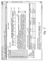
- FIG. 1 a preferred embodiment of the present invention is shown illustrating a global overview 100 of all rigs comprising an oil recovery system.
- a map pinpoints geographic locations of the rigs in the system of interest.
- a web page display is presented on a personal computer or PDA.
- the web page generated by the central server presents a geographic view of an oil recovery system.
- rig number 563 102 and rig number 569 104 is shown with a red status, indicating that a condition or reporting event of interest has occurred at rig number 563 and number 569.
- Rig number 569 106 is in Canada and rig number 563 108 is in the United States.
- Rig number 571 110 has a yellow status and rig number 567 112 has gray status. All other rigs shown in Figure 1 have a green status.
- rig number 569 106 or the Canadian region the display of Figure 2 appears.
- Figure 2 shows the Canadian region, which includes rig number 569. Notice that rig number 570 210 has a green status is now displayed on the more detailed Canadian region display. The green status geographical indicator for rig number 570 is suppressed and not shown in the broader display of Figure 1 so that the more severe red status of rig number 569 would be immediately visible and evident on the display of Figure 1 .
- the present invention displays the less severe status of rig number 570.
- the more severe status of rig number 569 bubbles up in the geographical display and is displayed first at a higher level in the geographical display hierarchy.
- the green status indicator of rig number 570 is shown in the panel 114 of Figure 1 and Figure 2 .
- the present invention presents a hybrid display in which all Health Check results are available in the panel 114 but worst case results are presented in the geographical displays of Figure 1 and Figure 2 .
- FIG. 3 the status display 314 of Figure 3 for rig number 569 is shown when a user clicks on rig number 569 104, 212 in Figure 1 or Figure 2 .
- Figure 3 illustrates that a rig number 569 component, "Rigsense” has a red indicator 312 .
- the Magnifying Glass icon 312 shown adjacent red indicator 310 indicates that more information is available regarding the red indicator 310 .
- additional panel displays 316 and 318 which are configurable, which perform additional informative functions.
- a summary panel 320 is displayed for rig number 569.
- the summary status panel contains operator reports from the oilrig. These operator reports are useful in diagnosing status and formulating a plan of action or notification.
- An AutoDriller status panel 316 is also displayed.
- Note that the Weight on Bit (WOB) indicator 317 is red in the AutoDriller status panel.
- a driller adjustable parameters panel 318 is also displayed.
- the device message block 413 may contain a part number 411 to expedite repair of a failure as reported.
- the particular part number and or drawing number necessary to perform a given repair associated with a given problem or severity report may be difficult to find in a vast inventory of parts and part numbers and drawings associated with a given failure. Otherwise, the recipient of a failure report may have to search via key words through a vast inventory of parts, part numbers and drawings associated with a given failure.
- the user may not be familiar with a particular vendor's part numbering system, thus, provision of the part number is a valuable expedient to trouble shooting.
- Figure 4A shows that the sensor group device status 412 is red with a Magnifying Glass icon 416 indicating that more information is available for the red sensor group device status indicator 412 .
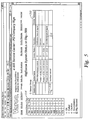
- a pop-up message 415 appears along with the Magnifying Glass stating "Click on Magnifying Glass for more details.” Clicking on the red sensor group 414 device Magnifying Glass 416 brings up the display 510 of Figure 5 , showing a detailed status for the sensor group device status. Note that there are two red indicators shown in Figure 5 for device status in the sensor group as follows: "Pump 3 Stroke Count Sensor" 516 and "Hookload Sensor" 514 .
- the Pump 3 red device status indicator has a informational comment 512 in the operation column of the display of Figure 5 , stating "Intermittent Loss of Signal.”
- the Hookload Sensor red device status indicator present an adjacent Magnifying Glass icon 518 with a message indicating that more information is available for the device status of the Hookload sensor by clicking on the Magnifying Glass icon. Clicking on the Manifying Glass indicator 518 for the Hookload sensor brings up the Hookload sensor panel 616 of Figure 6 , which shows that the device name "Barrier" 610 had a red device status indicator 612.
- the red device status for the Barrier displays an Operation message 614, stating, "Excessive ground current".
- Each colored indicator and accompanying operation message shown in the preferred displays illustrated in Figures 1-6 appeared in line of the Health Check performed at an oilrig and sent to the server in the structured protocol of the present invention.
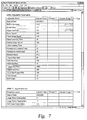
- Figure 7 illustrates a Driller Adjustable parameters display 710 with two red indicators showing that Drill Low Set Point 712 and Upper Set Point 714 are Outside Range. A Drilling Tuning parameters panel 716 is also displayed. Both panels indicate the current value, changed indicator and outside range indicator for each parameter displayed in the respective panels of Figure 7 .
- the display of Figure 7 is an alternative tabular display for rig status for a single rig.
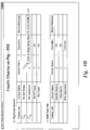
- Figure 8 illustrates a configuration or driller adjustable parameters status panel 810 for rig numbers 178-189.
- the display of Figure 8 is an alternative tabular display for rig status for plurality of rigs, e.g., rigs 178-189.
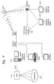
- a data acquisition system 1010 is shown in an oilrig environment connected to a plurality of legacy or Heath Check sensors 1012, which gathers data from the group of sensors monitoring the rig equipment, parameters and processes.
- the data acquisition system 1010 sends the acquired data from the sensors 1012 to a computer 1014 on which the preferred Health Check application of the present invention is running.
- the application of the present invention performs Health Checks logic on the acquired data and reports the results in the structured protocol to a user via satellite 1016 or some other form of electronic communication.
- a user may monitor health check status and receive notifications via a electronic receiver 1020, diagnostic station 1024 or mobile in field service vehicle 1022.
- the present invention is also useful for Process Monitoring, that is, to determine that equipment is being used properly to perform a designated process. For example, if rig operators are using an "override" during a certain system state indicative of a certain process, which is supposed to be run automatically rather than manually overridden, the present invention can perform a health check to detect this event of interest and report it to the central server. Knowledge of this occurrence enable central server personnel to detect and correct the inappropriate action of the operators. Moreover, the test to detect the inappropriate override stays in the system so that if new operators recreate the problem or trained operator backslide into using the manual override inappropriately, the central server personnel will be notified so that the problem can be address again. Thus, the Health Check system builds a cumulative base of operational check to insure that a process on a rig or oil recovery system runs in optimal fashion.
- Figure 10 is an illustration of a preferred Health Check system reporting health checks of multiple equipments, processes or systems from multiple oil rigs to multiple users.
- FIG. 11 the results of the tests are reported to the central server in a special protocol that contains heath check results data and describes the manner in which the data is constructed so that the data can be placed in a logical data structure or tree format and displayed.
- the root node 1110 usually an oilrig has a designation of "00".
- the first level of nodes 1112, 1113 etc. under the root node are named Aa, Ab, Ac, Ad, etc.
- Each subsequent layer of node is named with the name of the parent node followed by a designation of the current node.
- the root node 1110 is named "00"
- the first level of children nodes under the root node are named Aa 1112 and Ac 1113.
- the children of node Aa 1112 are named AaBa 1114, AaBd 1116, AaBe 1118 and AaBf 1120 as shown.
- the children of child node AaBa are named AaBaC1 1122 , AaBaC2 1124, AaBaC3 1126 and AaBaC4 1128 .
- AaBaC5 1130 The children of node AaBaC5 1130 are named AaBaC5Dg 1132, AaBaC5Dp 1134 , AaBaC5Dq 1136 and AaBaC5Ds 1138.
- a new test could be added to rig 569 number and the Heath Check status could be reported under node AaBaC5Dx 1140.
- Changes to the Health Checks running on any or all rigs does not require changes to the display or data base population application because the preferred communication protocol defines the data base layout and display layout.
- the leaf nodes of the tree structure represent Health Check results. Each node contains a test identifier, test result (red/yellow/green/gray), intermediate data, user-entered data and test description. Trouble shooting comments are provided at the central server based on reported errors. Test error codes are included in the node so that messages associated with the error codes are displayed to the appropriate user. Alternately, trouble shooting and other information can also be generated and appended to the results of the tests at rig site. Thus, no processing to determine rig status is done at the central server. Notifications are sent when deemed necessary by the application.
- Notification logic is configurable by service personnel at the central server or at the oilrig. Notification logic dictates that notifications are sent when an event occurs and the event has been selected for reporting as a notification to a user.
- the notification logic and a list of appropriate notification recipients in order of priority, that is, who to contact first, is retained at the central server.
- the event can be a report on an equipment status, process execution or an operational item.
- a user can check in with the central server of present invention to obtain a real time report of the status of an oilrig or multiple oilrigs. The requesting user will receive a severity report message indicating the status of the rig, for example, "okay” or "red/yellow/green/gray.”
- VICIS-ED is a drilling rig information and control system; it includes control of the drawworks via a joystick.
- an autodriller in VICIS-ED controls ROP, WOB, torque and/ delta-p parameters of the drilling process; it does this by controlling rate of line payout on the drawworks to limit the controlled parameters to setpoints specified by the driller. This health check tests verifies that the auto-driller is maintaining these parameters within acceptable limits. Acceptable control ranges typically have the following default values:
- the DCQA application computes the percent of time the feedback is within the allowable range. For each controller, this test is performed once a second when the controller has been in control for a minimum of 10 seconds. A count of acceptable and total test results is accumulated for each controller. At 6am for the previous 24 hours, this test computes the percent of time each controller's feedback was within the specified range, for all valid tests. If at least 20 tests for a controller were not done in the last 24 hours (which includes when there was no drilling or if the autodriller was not used), that controller's health check result is gray. Otherwise, the percentage of acceptable control counts is compared to pre-set values to categorize the result as red, yellow or green.
- VICIS-ED provides a keyed override switch, whose use should not be required for routine operation of the system.
- the status of this switch is monitored once a second, resulting in a count of times the switch was activated. A count greater than zero produces a red result for this health check, otherwise it is green. If this switch is used, this check is deemed failed and the number of engagements of this switch is documented in the command center log.
- This test monitors the state of the keyed override switch once a second and counts the number of times the switch has been pressed. If the switch is on when the test starts, that is counted as a key press.
- the health check is conducted, which consists of comparing the number of switch activations to a count of zero. If the switch has been pressed one time or more, the health check result is red; otherwise, it is green.
- This Health Check watches for a minimum of 3 consecutive joystick positions in same direction (i.e. all hoisting or all lowering) and compares the joystick position and block velocity in the third sample. If the joy stick position and the block velocity are in opposite directions, the Health Check increments the appropriate joystick hoist or lowers the error count. This test is not performed while the system is in keyed override or in a slip-and-cut mode.
- This Health Check detects watches for a minimum of 3 consecutive joystick positions in neutral direction. If the block is rising or falling in the third sample, it increments the joystick neutral error count. This Health Check is not performed while the system is in keyed override or in slip-and-cut mode.
- the health check result is red; otherwise, it is green.
- the joystick position is determined using the hoist and lower switches in the joystick assembly. The test also uses the following parameters:
- the Health Check monitors the bit-on-bottom state and auto-driller state from the drill logic in the drilling instrumentation system. It computes the percent of drilling time when the auto driller is in use on a one-second sampling as follows: 100 ⁇ number of times AD on AND bit ⁇ on ⁇ bottom / number of times bit ⁇ on ⁇ bottom .
- the test outputs the percent of drilling time the auto driller was used and this health check.
- This Health Check consists of comparing this percentage against a threshold of 98%. If the percentage is ⁇ 98%, the health check result is red; otherwise it is green. If no drilling was done, the health check result is gray. The percent of time on-bottom drilling is also computed, based on bit-on-bottom status.
- VICIS-ED A large number (more than 100) of system setting parameters exist in VICIS-ED; some are initial system settings, some are expert tuning adjustments and some are operational in nature and driller-specified. Many of these parameters preferably do not require changing on a daily basis, and knowledge of which parameters changed and how is vital for providing support to maintain system performance and ensure optimal usage.
- This test monitors all tuning parameters and maintains a count of changes by parameters and by groups of parameters (example - driller-initiated parameters). The following parameters are monitored, grouped as follows:
- Driller-Adjustable Operational Parameters Drill Stop Point; Low Set Point; High Set Point; Swab Speed for Trip Out; Surge Speed for Trip In; Stand Lowering Time; Surge Speed for Run Casing; Joint Lowering Time; Connection Lowering Speed; Connection Hoisting Speed; Trip In Kick Out Alert; Trip Out Height Alert; ROP Set point; WOB Set point; Delta P Set point; Torque Set point; Engine Cut Slip Speed Set point; Lines Strung; and Bail Length.
- Password-Protected Parameters Block weight; Brake horsepower; Encoder resolution; Brake air supply alarm low limit; Brake air supply alarm high limit; Engine tuning gain; Engine tuning integral; Brake hoisting tuning gain; Brake hoisting tuning integral; Brake lowering tuning gain; Brake lowering tuning integral; ROP loop tuning gain; ROP loop tuning integral; WOB loop tuning gain; WOB loop tuning integral; Torque loop tuning gain; Torque loop tuning integral; Delta P loop tuning gain; and Delta P loop tuning integral.
- This test records the value for each parameter upon startup. On a 24-hour basis starting at 6am CST, the test maintains a count of the number of times each parameter's value is changed, and if a parameter was outside the preferred range.
- the application outputs the following at 6am CST: a "value has changed” state for each parameter; a "value was out of range” state for each parameter; count of parameters changed per group; color-coded test result for each group; and color-coded test result for System Settings.
- test results for each parameter are color-coded in the following order:
- the group test results are color-coded as the "worst case" test result of all the parameters in the group.
- the BCS block control system limits the driller's operation of the block such that it does not exceed safe limits of operation. This check tests the operation of block control system compared to the preset limits it is required to enforce. To pass the test, the block should operate within the position/velocity envelope enclosed by upper and lower set points and maximum velocity set points. Pre-determined tolerance ranges are specified upon installation.
- the specification for VICIS-ED BCS operation is as follows:
- the test maintains a count of each of the following failures:
- the health check is not done if either the range override or the keyed over ride are on, or if in slip-and-cut mode. These counts are reset to zero at 6am and are maintained on a 24-hour basis. At 6am, the counts will be summed. If this sum is greater than zero, the health check result is red; otherwise, it is green.
- Elevator position at least one value has been received, AND current value must be between -20ft and 150ft.
- Block velocity at least one value has been received, AND current value must be between-5000ft/min and 5000ft/min.
- Keyed override switch state at least one value has been received, AND current value must be 0 or 1.
- Weight-on-bit at least one value has been received
- the present invention is implemented as a set of instructions on a computer readable medium, comprising ROM, RAM, CD ROM, Flash or any other computer readable medium, now known or unknown that when executed cause a computer to implement the method of the present invention.
Landscapes
- Engineering & Computer Science (AREA)
- Theoretical Computer Science (AREA)
- Business, Economics & Management (AREA)
- Entrepreneurship & Innovation (AREA)
- Human Resources & Organizations (AREA)
- Strategic Management (AREA)
- Physics & Mathematics (AREA)
- General Physics & Mathematics (AREA)
- Economics (AREA)
- Operations Research (AREA)
- Game Theory and Decision Science (AREA)
- Development Economics (AREA)
- General Engineering & Computer Science (AREA)
- Marketing (AREA)
- Tourism & Hospitality (AREA)
- Quality & Reliability (AREA)
- Human Computer Interaction (AREA)
- General Business, Economics & Management (AREA)
- Educational Administration (AREA)
- Telephonic Communication Services (AREA)
- Alarm Systems (AREA)
- Management, Administration, Business Operations System, And Electronic Commerce (AREA)
- Testing And Monitoring For Control Systems (AREA)
Claims (17)
- Verfahren zum Überwachen und Analysieren von einer Vielzahl von Signalen von Sensoren in Bohrlochbohranlagen, die ein Ölgewinnungssystem umfassen, wobei das vorfahren das Folgende umfasst:Bereitstellen von einer Vielzahl von Sensoren (1012) zur Überwachung des Status von einer Vielzahl von Ölbohranlagen (Anlage-A, Anlage-B), die in dem System umfasst sind, und zum Übertragen von Signalen, die für Parameter bezeichnend sind, die mit dem Betrieb der Bohrlochbohranlagen in Beziehung stehen;Überwachen von Information, die für Ereignisse auf jeder Ölbohranlage (Anlage-A, Anlage-B) bezeichnend ist, mit den Sensoren;Übertragen von Signalen von den Sensoren (1012) zu einer Verarbeitungseinheit auf jeder Ölbohranlage (Anlage-A, Anlage-B), wobei die Signale von den Sensoren (1012) für Ereignisse auf dieser Anlage (Anlage-A, Anlage-B) bezeichnend sind, wobei die Verarbeitungseinheit Signale von den Sensoren analysiert, wobei ein Satz von Gesundheitscheckregeln verwendet wird, die logische Regeln, Inputs und Outputs umfassen, um Ereignisse zu definieren, die mit dem Status der Bohranlage in Beziehung stehen, und eine Schweregradangabe für jedes Ereignis bestimmt;Berichten der Ereignisse und der Schweregradangaben von der Verarbeitungseinheit auf jeder Ölbohranlage (Anlage-A, Anlage-B) zu einem zentralen Server, der ein Programm zum Berichten und Darstellen von Ergebnissen umfasst, wobei die Ereignisse in einem Protokoll berichtet werden, welches eine hierarchische Baumknotendatenstruktur definiert,wobei die Ergebnisse aus der Abwendung der Gesundheitscheckregeln ein unterster Knoten der Baumknotenstruktur sind; undDarstellen der Ereignisschweregradangaben auf einer zentral zugänglichen Anzeige.
- Verfahren nach Anspruch 1, ferner umfassend
eine Verarbeitungseinheit auf jeder Anlage (Anlage-A, Anlage-B), die die Schweregradangaben in einer hierarchischen Reihenfolge bereitstellt und die Schweregradangaben in einer Reihenfolge der Schwere nach darstellt, wobei eine höhere Schweregradangabe vor einer niedrigeren Schweregradangabe dargestellt wird. - Verfahren nach Anspruch 1 oder 2, ferner umfassend
das Berichten einer Worst-Case-Schweregradangabe vor dem Berichten von anderen Schweregradangaben, die nicht so schwerwiegend wie die Worst-Case-Schweregradangabe sind, und
das Darstellen der Worst-Case-Schweregradangabe vor den anderen Schweregradangaben. - Verfahren nach einem der vorhergehenden Ansprüche, ferner umfassend das Verändern von mindestens einer der Gesundheitscheckregeln von dem Satz von Gesundheitscheckregeln auf jeder Anlage (Anlage-A, Anlage-B), ohne dass dabei das Programm in dem zentralen Server verändert wird.
- Verfahren nach einem der vorhergehenden Ansprüche, wobei
der zentrale Server eine Datenbasispopulation, eine Abwendung zum Berichten von Daten und eine Abwendung zum Darstellen von Daten aufweist,
wobei das Verfahren ferner das Verändern von einer Gesundheitscheckregel in der Verarbeitungseinheit umfasst, ohne dass dabei die Datenbasispopulation, die Anwendungen zum Berichten von Daten und die Anwendungen zum Darstellen von Daten des zentralen Servers verändert werden. - Verfahren nach einem der vorhergehenden Ansprüche, ferner umfassend das Laufenlassen des Gesundheitschecks in Echtzeit, um Ergebnisse in Bezug auf den derzeitigen Status der Geräte auf jeder Anlage (Anlage-A, Anlage-B) bereitzustellen und um ein mögliches Versagen von Geräten anzuzeigen.
- Verfahren nach einem der vorhergehenden Ansprüche, wobei auf dem zentralen Server keine Verarbeitung der Ergebnisse erfolgt.
- Verfahren nach einem der vorhergehenden Ansprüche, ferner umfassend das Verfügbarmachen der Anzeige von den Schweregradangaben für eine Betrachtung an einer zentralen Einrichtung oder an verteilten Orten eines Kommunikationsnetzwerks.
- Verfahren nach einem der vorhergehenden Ansprüche, wobei das Verfahren in Echtzeit erfolgt.
- Verfahren nach einem der vorhergehenden Ansprüche, wobei das Verfahren automatisch erfolgt.
- Verfahren nach einem der vorhergehenden Ansprüche, ferner umfassend das Darstellen eines Status von der Bohranlage (Anlage-A, Anlage-B) in einer geographischen Anzeige.
- Verfahren nach Anspruch 11, ferner umfassend das Darstellen der Schweregradangaben in der geographischen Anzeige.
- Verfahren nach einem der vorhergehenden Ansprüche, ferner umfassend das Senden von einer Bestätigungsmeldung von einem Ereignis an einen Primärkontakt, das Empfangen von einer Kenntnisnahme von dem Primärkontakt und andernfalls das Senden der Bestätigungsmeldung an einen Sekundärkontakt.
- Verfahren nach einem der vorhergehenden Ansprüche, ferner umfassend das Senden von einer Meldung von einem Ereignis an mehrere Kontakte.
- Verfahren nach einem der vorhergehenden Ansprüche, wobei jede Bohranlage (Anlage-A, Anlage-B) ein Informations- und Kontrollsystem zum Kontrollieren des Bohrfortschritts (ROP; Engl.: rate of penetration), des Bohrerdrucks (WOB; Engl.: weight on bit), des Drehmoments und des Differenzdrucks (delta-p) aufweist und wobei die Gesundheitschecks verifizieren, dass ein automatischer Bohrer in dem Informations- und Kontrollsystem diese Parameter innerhalb von akzeptablen Grenzen aufrechterhält.
- Apparat zum Überwachen und Analysieren von einer Vielzahl von Signalen von Sensoren in Bohrlochbohranlagen, die ein Ölgewinnungssystem umfassen, wobei der Apparat das Folgende umfasst:eine Vielzahl von Sensoren (1012), die auf einer Vielzahl von Ölbohranlagen (Anlage-A, Anlage-B) bereitgestellt ist, zur Überwachung des Status von der Vielzahl von Ölbohranlagen, die in dem System umfasst sind, und zum Übertragen von Signalen, die für Parameter bezeichnend sind, die mit dem Betrieb der Bohrlochbohranlagen in Beziehung stehen;Mittel zum Überwachen von Information, die für Ereignisse auf jeder Ölbohranlage bezeichnend ist, mit den Sensoren;eine Verarbeitungseinheit, die auf jeder Ölbohranlage (Anlage-A, Anlage-B) bereitgestellt ist;Mittel zum Übertragen von Signalen von den Sensoren zu der Verarbeitungseinheit auf jeder Ölbohranlage (Anlage-A, Anlage-B), wobei die Signale von den Sensoren für Ereignisse auf dieser Anlage bezeichnend sind, wobei die Verarbeitungseinheit Mittel zum Analysieren der Signale von den Sensoren umfasst, wobei ein Satz von Gesundheitscheckregeln verwendet wird, die auf der Verarbeitungseinheit bereitgestellt sind und die logische Regeln, Inputs und Outputs umfassen, um Ereignisse zu definieren, die mit dem Status der Bohranlage in Beziehung stehen, und Mittel zum Bestimmen von einer Schweregradangabe für jedes Ereignis umfasst;einen zentralen Server, der ein Programm umfasst, das für das Berichten und Darstellen von Ergebnissen konfiguriert ist;Mittel zum Berichten von Ereignissen und Schweregradangaben von der Verarbeitungseinheit auf jeder Ölbohranlage (Anlage-A, Anlage-B) zu dem Programm auf dem zentralen Server;ein Protokoll für das Berichten von den Ereignissen, wobei das Protokoll eine hierarchische Baumknotendatenstruktur definiert, wobei die Ergebnisse aus der Abwendung der Gesundheitscheckregeln ein unterster Knoten der Baumknotenstruktur sind; undeine zentral zugängliche Anzeige und Mittel zum Anzeigen der Ereignisschweregradangaben auf der zentral zugänglichen Anzeige;wobei der Apparat konfiguriert ist, um das Verfahren nach einem der vorhergehenden Ansprüche durchzuführen.
- Computerlesbares Medium, das Instruktionen enthält, die, wenn sie durch einen Computer ausgeführt werden, ein Verfahren nach einem der Ansprüche 1 - 15 implementieren.
Applications Claiming Priority (5)
| Application Number | Priority Date | Filing Date | Title |
|---|---|---|---|
| US42426202P | 2002-11-06 | 2002-11-06 | |
| US424262P | 2002-11-06 | ||
| US373216 | 2003-02-24 | ||
| US10/373,216 US6907375B2 (en) | 2002-11-06 | 2003-02-24 | Method and apparatus for dynamic checking and reporting system health |
| PCT/US2003/035594 WO2004044695A2 (en) | 2002-11-06 | 2003-11-06 | A method and apparatus for dynamic checking and reporting system health |
Publications (3)
| Publication Number | Publication Date |
|---|---|
| EP1559055A2 EP1559055A2 (de) | 2005-08-03 |
| EP1559055A4 EP1559055A4 (de) | 2014-10-29 |
| EP1559055B1 true EP1559055B1 (de) | 2016-07-20 |
Family
ID=32179567
Family Applications (1)
| Application Number | Title | Priority Date | Filing Date |
|---|---|---|---|
| EP03781827.5A Expired - Lifetime EP1559055B1 (de) | 2002-11-06 | 2003-11-06 | Verfahren und vorrichtung zum dynamischen prüfen und melden der systemintegrität |
Country Status (6)
| Country | Link |
|---|---|
| US (1) | US6907375B2 (de) |
| EP (1) | EP1559055B1 (de) |
| AU (1) | AU2003287582A1 (de) |
| CA (1) | CA2499303C (de) |
| NO (1) | NO20051135L (de) |
| WO (1) | WO2004044695A2 (de) |
Families Citing this family (110)
| Publication number | Priority date | Publication date | Assignee | Title |
|---|---|---|---|---|
| US8209203B1 (en) * | 2001-07-30 | 2012-06-26 | Ods-Petrodata, Ltd. | System, method, and computer program for tracking floating production system market and technical data |
| US20050242003A1 (en) * | 2004-04-29 | 2005-11-03 | Eric Scott | Automatic vibratory separator |
| CA2493091C (en) * | 2002-07-26 | 2008-12-30 | Varco I/P, Inc. | Automated rig control management system |
| US8312995B2 (en) | 2002-11-06 | 2012-11-20 | National Oilwell Varco, L.P. | Magnetic vibratory screen clamping |
| US20060105896A1 (en) * | 2004-04-29 | 2006-05-18 | Smith George E | Controlled centrifuge systems |
| US8172740B2 (en) | 2002-11-06 | 2012-05-08 | National Oilwell Varco L.P. | Controlled centrifuge systems |
| US20040181549A1 (en) * | 2003-03-13 | 2004-09-16 | Pate James D. | Direct maintenance system for unscheduled, predictive, and preventive maintenance of critical process equipment |
| US20040267694A1 (en) * | 2003-06-30 | 2004-12-30 | Satoshi Sakai | Machine-readable medium & data management system and method for tracking real-world objects |
| US7946356B2 (en) * | 2004-04-15 | 2011-05-24 | National Oilwell Varco L.P. | Systems and methods for monitored drilling |
| US8069239B2 (en) * | 2004-07-20 | 2011-11-29 | Beckman Coulter, Inc. | Centralized monitor and control system for laboratory instruments |
| US20060248468A1 (en) * | 2005-04-29 | 2006-11-02 | Larry Constantine | Apparatus and method for controlling visibility of data with visual nesting |
| US7505871B2 (en) * | 2006-08-11 | 2009-03-17 | Varco I/P, Inc. | Diagnosis and troubleshooting for above-ground well systems |
| US9103195B2 (en) * | 2006-09-27 | 2015-08-11 | Halliburton Energy Services, Inc. | Monitor and control of directional drilling operations and simulations |
| US9359882B2 (en) | 2006-09-27 | 2016-06-07 | Halliburton Energy Services, Inc. | Monitor and control of directional drilling operations and simulations |
| US20080083566A1 (en) | 2006-10-04 | 2008-04-10 | George Alexander Burnett | Reclamation of components of wellbore cuttings material |
| US8215417B2 (en) * | 2007-01-23 | 2012-07-10 | Canrig Drilling Technology Ltd. | Method, device and system for drilling rig modification |
| US8204692B2 (en) * | 2006-12-18 | 2012-06-19 | Baker Hughes Incorporated | System, program product, and method for drilling rig activity accounting visualization |
| US7636614B2 (en) * | 2007-01-31 | 2009-12-22 | Halliburton Energy Services, Inc. | Systems for managing flow control valves in process systems |
| WO2008093054A2 (en) * | 2007-01-31 | 2008-08-07 | Hallibruton Energy Services, Inc. | Systems and methods for monitoring sensor and actuator health and performance |
| US20080179056A1 (en) * | 2007-01-31 | 2008-07-31 | Halliburton Energy Services Inc. | Systems for monitoring sensor and actuator health and performance |
| US7606636B2 (en) * | 2007-01-31 | 2009-10-20 | Halliburton Energy Services, Inc. | Methods for managing flow control valves in process systems |
| US7574325B2 (en) * | 2007-01-31 | 2009-08-11 | Halliburton Energy Services, Inc. | Methods to monitor system sensor and actuator health and performance |
| US20080281660A1 (en) * | 2007-05-13 | 2008-11-13 | System Services, Inc. | System, Method and Apparatus for Outsourcing Management of One or More Technology Infrastructures |
| US20080281607A1 (en) * | 2007-05-13 | 2008-11-13 | System Services, Inc. | System, Method and Apparatus for Managing a Technology Infrastructure |
| US20090045973A1 (en) * | 2007-08-16 | 2009-02-19 | Rodney Paul F | Communications of downhole tools from different service providers |
| US8622220B2 (en) | 2007-08-31 | 2014-01-07 | Varco I/P | Vibratory separators and screens |
| US9717896B2 (en) | 2007-12-18 | 2017-08-01 | Gearbox, Llc | Treatment indications informed by a priori implant information |
| US8636670B2 (en) | 2008-05-13 | 2014-01-28 | The Invention Science Fund I, Llc | Circulatory monitoring systems and methods |
| US20090287120A1 (en) | 2007-12-18 | 2009-11-19 | Searete Llc, A Limited Liability Corporation Of The State Of Delaware | Circulatory monitoring systems and methods |
| GB2461856B (en) * | 2008-07-11 | 2012-12-19 | Vetco Gray Controls Ltd | Testing of an electronics module |
| US9073104B2 (en) | 2008-08-14 | 2015-07-07 | National Oilwell Varco, L.P. | Drill cuttings treatment systems |
| US20100056873A1 (en) * | 2008-08-27 | 2010-03-04 | Allen Paul G | Health-related signaling via wearable items |
| US8284046B2 (en) | 2008-08-27 | 2012-10-09 | The Invention Science Fund I, Llc | Health-related signaling via wearable items |
| US8094009B2 (en) * | 2008-08-27 | 2012-01-10 | The Invention Science Fund I, Llc | Health-related signaling via wearable items |
| US8125331B2 (en) * | 2008-08-27 | 2012-02-28 | The Invention Science Fund I, Llc | Health-related signaling via wearable items |
| US8130095B2 (en) * | 2008-08-27 | 2012-03-06 | The Invention Science Fund I, Llc | Health-related signaling via wearable items |
| US20100078216A1 (en) * | 2008-09-25 | 2010-04-01 | Baker Hughes Incorporated | Downhole vibration monitoring for reaming tools |
| US8556083B2 (en) | 2008-10-10 | 2013-10-15 | National Oilwell Varco L.P. | Shale shakers with selective series/parallel flow path conversion |
| US9079222B2 (en) | 2008-10-10 | 2015-07-14 | National Oilwell Varco, L.P. | Shale shaker |
| WO2010068740A2 (en) * | 2008-12-10 | 2010-06-17 | Simple One Media, Llc | Statistical and visual sports analysis system |
| US20110270525A1 (en) * | 2010-04-30 | 2011-11-03 | Scott Hunter | Machines, systems, computer-implemented methods, and computer program products to test and certify oil and gas equipment |
| US8844042B2 (en) | 2010-06-16 | 2014-09-23 | Microsoft Corporation | System state based diagnostic scan |
| CN103562492A (zh) * | 2011-03-10 | 2014-02-05 | 界标制图有限公司 | 用于实时监测多口井的操作数据的系统与方法 |
| WO2012138321A1 (en) * | 2011-04-04 | 2012-10-11 | Landmark Graphics Corporation | Safety barrier alert |
| RU2591668C2 (ru) * | 2011-08-30 | 2016-07-20 | Халлибертон Энерджи Сервисез, Инк. | Способ и система комплексного управления подземными работами |
| JP5807990B2 (ja) * | 2011-09-22 | 2015-11-10 | アイトーン、インコーポレイテッド | 自律移動ロボット用の監視、診断及び追跡ツール |
| EP2834460A2 (de) * | 2012-04-03 | 2015-02-11 | National Oilwell Varco, L.P. | Bohrsteuerungssystem |
| USD713825S1 (en) | 2012-05-09 | 2014-09-23 | S.P.M. Flow Control, Inc. | Electronic device holder |
| US9525976B2 (en) * | 2012-05-10 | 2016-12-20 | Honeywell International Inc. | BIM-aware location based application |
| EP2855836B1 (de) | 2012-05-25 | 2019-03-06 | S.P.M. Flow Control, Inc. | Vorrichtung und verfahren zur beurteilung von systemen im zusammenhang mit bohrlochköpfen |
| US20140067352A1 (en) * | 2012-09-06 | 2014-03-06 | Intellicess Inc. | Presenting attributes of interest in a physical system using process maps based modeling |
| US10171999B2 (en) | 2012-12-07 | 2019-01-01 | Sitepro, Llc | Mobile surveillance unit |
| US8649909B1 (en) | 2012-12-07 | 2014-02-11 | Amplisine Labs, LLC | Remote control of fluid-handling devices |
| US9643111B2 (en) | 2013-03-08 | 2017-05-09 | National Oilwell Varco, L.P. | Vector maximizing screen |
| WO2014203245A2 (en) | 2013-06-20 | 2014-12-24 | Aspect International (2015) Private Limited | An nmr/mri-based integrated system for analyzing and treating of a drilling mud for drilling mud recycling process and methods thereof |
| US9626432B2 (en) * | 2013-09-09 | 2017-04-18 | International Business Machines Corporation | Defect record classification |
| WO2015060836A1 (en) * | 2013-10-23 | 2015-04-30 | Halliburton Energy Services, Inc. | Sealing element wear detection for wellbore devices |
| US8779919B1 (en) * | 2013-11-03 | 2014-07-15 | Instant Care, Inc. | Event communication apparatus and method |
| US9494503B2 (en) | 2013-11-06 | 2016-11-15 | Aspect Imaging Ltd. | Inline rheology/viscosity, density, and flow rate measurement |
| MX2014015407A (es) | 2014-03-23 | 2015-09-22 | Aspect Internat 2015 Private Ltd | Medios y metodos para el analisis multimodal y el tratamiento del lodo de perforacion. |
| US9957781B2 (en) | 2014-03-31 | 2018-05-01 | Hitachi, Ltd. | Oil and gas rig data aggregation and modeling system |
| WO2016019039A1 (en) | 2014-07-30 | 2016-02-04 | S.P.M. Flow Control, Inc. | Band with rfid chip holder and identifying component |
| WO2016027122A1 (en) * | 2014-08-18 | 2016-02-25 | Magma Products Group Ltd. | Commissioning management system |
| USD750516S1 (en) | 2014-09-26 | 2016-03-01 | S.P.M. Flow Control, Inc. | Electronic device holder |
| US9547547B2 (en) | 2014-11-28 | 2017-01-17 | Software Ag | Systems and/or methods for handling erroneous events in complex event processing (CEP) applications |
| WO2016094530A1 (en) | 2014-12-09 | 2016-06-16 | Schlumberger Canada Limited | Electric submersible pump event detection |
| WO2016100973A1 (en) | 2014-12-19 | 2016-06-23 | Schlumberger Technology Corporation | Method of creating and executing a plan |
| US9626729B2 (en) | 2014-12-22 | 2017-04-18 | Amplisine Labs, LLC | Oil-field trucking dispatch |
| CN107207188B (zh) | 2014-12-29 | 2021-02-12 | 奥的斯电梯公司 | 维持系统性能的系统与方法 |
| US20180012310A1 (en) * | 2015-01-06 | 2018-01-11 | Schlumberger Technology Corporation | Creating and executing a well construction/operation plan |
| WO2016116926A1 (en) | 2015-01-19 | 2016-07-28 | Aspect International (2015) Private Limited | Nmr-based systems for crude oil enhancement and methods thereof |
| CN106053299B (zh) | 2015-04-12 | 2020-10-30 | 艾斯拜克特Ai有限公司 | 非圆形横截面管道中的流体的nmr成像 |
| US10891573B2 (en) * | 2015-04-19 | 2021-01-12 | Schlumberger Technology Corporation | Wellsite report system |
| US11037039B2 (en) | 2015-05-21 | 2021-06-15 | S.P.M. Flow Control, Inc. | Method and system for securing a tracking device to a component |
| CN106324010A (zh) | 2015-07-02 | 2017-01-11 | 艾斯拜克特Ai有限公司 | 使用mr设备对在管道中流动的流体的分析 |
| US10229360B2 (en) | 2015-08-10 | 2019-03-12 | Saudi Arabian Oil Company | Diagnosing reservoir health |
| WO2017030870A1 (en) | 2015-08-14 | 2017-02-23 | S.P.M. Flow Control, Inc. | Carrier and band assembly for identifying and managing a component of a system associated with a wellhead |
| WO2017044105A1 (en) * | 2015-09-10 | 2017-03-16 | Hitachi, Ltd. | Method and apparatus for well spudding scheduling |
| US11915178B2 (en) * | 2015-09-22 | 2024-02-27 | Nmetric, Llc | Cascading notification system |
| US20170122095A1 (en) * | 2015-11-03 | 2017-05-04 | Ubiterra Corporation | Automated geo-target and geo-hazard notifications for drilling systems |
| US9848061B1 (en) | 2016-10-28 | 2017-12-19 | Vignet Incorporated | System and method for rules engine that dynamically adapts application behavior |
| US9928230B1 (en) | 2016-09-29 | 2018-03-27 | Vignet Incorporated | Variable and dynamic adjustments to electronic forms |
| US12217036B2 (en) | 2016-02-10 | 2025-02-04 | Vignet Incorporated | Automating interactions for health data collection and patient engagement |
| US10655996B2 (en) | 2016-04-12 | 2020-05-19 | Aspect Imaging Ltd. | System and method for measuring velocity profiles |
| CA3045755C (en) | 2016-12-30 | 2024-01-23 | Evolution Engineering Inc. | System and method for data telemetry among adjacent boreholes |
| US20180283137A1 (en) * | 2017-03-30 | 2018-10-04 | Nabors Drilling Technologies Usa, Inc. | Integrated Remote Choke System |
| CN108387342A (zh) * | 2018-01-08 | 2018-08-10 | 联创汽车电子有限公司 | Eps非接触式扭矩传感器故障识别系统及其识别方法 |
| WO2019147689A1 (en) | 2018-01-23 | 2019-08-01 | Baker Hughes, A Ge Company, Llc | Methods of evaluating drilling performance, methods of improving drilling performance, and related systems for drilling using such methods |
| US11029810B2 (en) * | 2018-05-07 | 2021-06-08 | Otis Elevator Company | Equipment service graphical interface |
| US11808903B2 (en) | 2018-05-12 | 2023-11-07 | Schlumberger Technology Corporation | Seismic data interpretation system |
| US12147920B2 (en) | 2018-12-04 | 2024-11-19 | Schlumberger Technology Corporation | Multi-domain planning and execution |
| US11288609B2 (en) | 2018-12-04 | 2022-03-29 | Schlumberger Technology Corporation | Systems and methods for executing a plan associated with multiple equipment by using rule-based inference |
| CA3043421A1 (en) | 2018-05-15 | 2019-11-15 | Schlumberger Canada Limited | Operations management network system and method |
| US10808517B2 (en) | 2018-12-17 | 2020-10-20 | Baker Hughes Holdings Llc | Earth-boring systems and methods for controlling earth-boring systems |
| US12146394B2 (en) | 2018-12-28 | 2024-11-19 | Upwing Energy, Inc. | Controlling downhole-type rotating machines |
| US11753890B2 (en) | 2019-01-15 | 2023-09-12 | Schlumberger Technology Corporation | Real-time pump-down perforating data acquisition and application automation response |
| EP3698877B1 (de) | 2019-02-19 | 2021-11-10 | Alfa Laval Corporate AB | Verfahren zur steuerung eines zentrifugalabscheiders sowie zentrifugalabscheider |
| US11371330B2 (en) | 2019-07-24 | 2022-06-28 | Schlumberger Technology Corporation | Coordinated pumping operations |
| US11041371B2 (en) * | 2019-08-27 | 2021-06-22 | Schlumberger Technology Corporation | Adaptive probabilistic health management for rig equipment |
| CN110575953A (zh) * | 2019-10-19 | 2019-12-17 | 横县南香茶厂 | 一种变直线茶叶振动筛 |
| US11933156B2 (en) | 2020-04-28 | 2024-03-19 | Schlumberger Technology Corporation | Controller augmenting existing control system |
| US11867054B2 (en) | 2020-05-11 | 2024-01-09 | Saudi Arabian Oil Company | Systems and methods for estimating well parameters and drilling wells |
| US20210350335A1 (en) * | 2020-05-11 | 2021-11-11 | Saudi Arabian Oil Company | Systems and methods for automatic generation of drilling schedules using machine learning |
| CN112230760B (zh) * | 2020-09-17 | 2022-09-20 | 淮南师范学院 | 一种基于用户操作及生物特征相结合的分析系统和方法 |
| US12379707B2 (en) * | 2020-10-23 | 2025-08-05 | Schlumberger Technology Corporation | Monitoring equipment health |
| US20220277250A1 (en) * | 2021-03-01 | 2022-09-01 | Saudi Arabian Oil Company | System and method for rig evaluation |
| CN113294143B (zh) * | 2021-04-16 | 2023-09-26 | 中煤能源研究院有限责任公司 | 一种煤层底板灰岩水害地面超前区域探查治理效果评价方法 |
| CN113399277B (zh) * | 2021-08-18 | 2021-10-29 | 山东柏源技术有限公司 | 一种石油钻具自动化检测系统 |
| CN116603727B (zh) * | 2023-07-19 | 2023-11-17 | 四川磊蒙机械设备有限公司 | 双重振动振动筛及其筛板组件 |
| CN116720853B (zh) * | 2023-08-09 | 2023-10-27 | 山东立鑫石油机械制造有限公司 | 一种超稠油石油钻采设备安全性能综合监控方法及系统 |
Family Cites Families (23)
| Publication number | Priority date | Publication date | Assignee | Title |
|---|---|---|---|---|
| US3219107A (en) * | 1960-09-14 | 1965-11-23 | Socony Mobil Oil Co Inc | Remote and automatic control of petroleum production |
| US3629859A (en) * | 1969-11-14 | 1971-12-21 | Halliburton Co | Oil field production automation and apparatus |
| US4432064A (en) * | 1980-10-27 | 1984-02-14 | Halliburton Company | Apparatus for monitoring a plurality of operations |
| US4573115A (en) * | 1983-10-28 | 1986-02-25 | Standard Oil Company (Indiana) | Supervisory control system for remotely monitoring and controlling at least one operational device |
| US4794534A (en) * | 1985-08-08 | 1988-12-27 | Amoco Corporation | Method of drilling a well utilizing predictive simulation with real time data |
| KR890007306A (ko) * | 1987-10-30 | 1989-06-19 | 제트.엘.더머 | 온라인 밸브 진단 감시 시스템 |
| US5274572A (en) | 1987-12-02 | 1993-12-28 | Schlumberger Technology Corporation | Method and apparatus for knowledge-based signal monitoring and analysis |
| US5278549A (en) * | 1992-05-01 | 1994-01-11 | Crawford James R | Wireline cycle life counter |
| US5732776A (en) * | 1995-02-09 | 1998-03-31 | Baker Hughes Incorporated | Downhole production well control system and method |
| US5706896A (en) * | 1995-02-09 | 1998-01-13 | Baker Hughes Incorporated | Method and apparatus for the remote control and monitoring of production wells |
| US6408953B1 (en) * | 1996-03-25 | 2002-06-25 | Halliburton Energy Services, Inc. | Method and system for predicting performance of a drilling system for a given formation |
| US6693553B1 (en) * | 1997-06-02 | 2004-02-17 | Schlumberger Technology Corporation | Reservoir management system and method |
| US6012016A (en) * | 1997-08-29 | 2000-01-04 | Bj Services Company | Method and apparatus for managing well production and treatment data |
| US8073721B1 (en) * | 1999-05-24 | 2011-12-06 | Computer Associates Think, Inc. | Service level management |
| US6519568B1 (en) * | 1999-06-15 | 2003-02-11 | Schlumberger Technology Corporation | System and method for electronic data delivery |
| US6553336B1 (en) * | 1999-06-25 | 2003-04-22 | Telemonitor, Inc. | Smart remote monitoring system and method |
| US7783507B2 (en) * | 1999-08-23 | 2010-08-24 | General Electric Company | System and method for managing a fleet of remote assets |
| US7259688B2 (en) * | 2000-01-24 | 2007-08-21 | Shell Oil Company | Wireless reservoir production control |
| US6917845B2 (en) * | 2000-03-10 | 2005-07-12 | Smiths Detection-Pasadena, Inc. | Method for monitoring environmental condition using a mathematical model |
| FR2808335B1 (fr) * | 2000-04-28 | 2002-07-12 | Inst Francais Du Petrole | Methode et systeme de synchronisation des elements d'un dispositif sismique utilisant un reseau de transmission standard et une reference temporelle externe |
| US6801135B2 (en) * | 2000-05-26 | 2004-10-05 | Halliburton Energy Services, Inc. | Webserver-based well instrumentation, logging, monitoring and control |
| US6393363B1 (en) * | 2000-06-28 | 2002-05-21 | Schlumberger Technology Corporation | Method and apparatus for the measurement of the electrical resistivity of geologic formations employing modeling data |
| US20020035551A1 (en) * | 2000-09-20 | 2002-03-21 | Sherwin Rodney D. | Method and system for oil and gas production information and management |
-
2003
- 2003-02-24 US US10/373,216 patent/US6907375B2/en not_active Expired - Lifetime
- 2003-11-06 CA CA002499303A patent/CA2499303C/en not_active Expired - Fee Related
- 2003-11-06 EP EP03781827.5A patent/EP1559055B1/de not_active Expired - Lifetime
- 2003-11-06 AU AU2003287582A patent/AU2003287582A1/en not_active Abandoned
- 2003-11-06 WO PCT/US2003/035594 patent/WO2004044695A2/en not_active Ceased
-
2005
- 2005-03-03 NO NO20051135A patent/NO20051135L/no not_active Application Discontinuation
Also Published As
| Publication number | Publication date |
|---|---|
| US20040088115A1 (en) | 2004-05-06 |
| CA2499303C (en) | 2010-02-02 |
| EP1559055A2 (de) | 2005-08-03 |
| US6907375B2 (en) | 2005-06-14 |
| WO2004044695A2 (en) | 2004-05-27 |
| AU2003287582A8 (en) | 2004-06-03 |
| WO2004044695A3 (en) | 2004-09-23 |
| NO20051135L (no) | 2005-05-12 |
| AU2003287582A1 (en) | 2004-06-03 |
| EP1559055A4 (de) | 2014-10-29 |
| CA2499303A1 (en) | 2004-05-27 |
Similar Documents
| Publication | Publication Date | Title |
|---|---|---|
| EP1559055B1 (de) | Verfahren und vorrichtung zum dynamischen prüfen und melden der systemintegrität | |
| US20050222772A1 (en) | Oil rig choke control systems and methods | |
| KR102648377B1 (ko) | 네트워크 케이블 품질 모니터링이 가능한 ai 통합배선반 및 이를 이용한 방법 | |
| US6131112A (en) | Method and apparatus for integrated network and systems management | |
| AU2015204064B2 (en) | Systems and methods to visualize component health and preventive maintenance needs for subsea control subsystem components | |
| US20070222585A1 (en) | System and method for visual representation of a catastrophic event and coordination of response | |
| US7429921B2 (en) | Communication system for a fire alarm or security system | |
| WO2005094344A2 (en) | Detecting performance in enterprise software applications | |
| JP2014209346A (ja) | プロセスプラント内の総資産使用指標 | |
| US20070035398A1 (en) | External status asset monitor | |
| KR20060105748A (ko) | 설비 부품의 감시 및 교체 관리 시스템 | |
| CN1993718A (zh) | 因特网促进的火警监视、控制系统和方法 | |
| Jiang et al. | System hazard analysis of tower crane in different phases on construction site | |
| KR102680066B1 (ko) | 네트워크 케이블 품질 모니터링이 가능한 지능형 통합배선반 | |
| WO2001075697A1 (en) | A knowledge system and methods of business alerting and business analysis | |
| Atchison | Automated well control: From automated detection to automated shut-in | |
| CN106549831A (zh) | 一种信息系统的健康分析方法和系统 | |
| CN112489373B (zh) | 一种地质灾害的监测方法、后台监控中心和监测系统 | |
| Padarthi et al. | Iot-based embedded sensor system for real-time health monitoring of composite structures for large-scale industrial operations | |
| Wolthusen | GIS-based command and control infrastructure for critical infrastructure protection | |
| KR102640451B1 (ko) | 사업장재해 통합관제 시스템 및 그 방법 | |
| KR102142856B1 (ko) | X-Ray 검색장비 원격 모니터링 통합 관리제어 시스템 및 이를 이용한 방법 | |
| CN116266426A (zh) | 火灾事件模式分析和交叉建筑物数据分析 | |
| US11334061B2 (en) | Method to detect skill gap of operators making frequent inadvertent changes to the process variables | |
| KR101738770B1 (ko) | 엔터프라이즈 비즈니스 서비스 레벨의 통합 모니터링 방법 및 시스템 |
Legal Events
| Date | Code | Title | Description |
|---|---|---|---|
| PUAI | Public reference made under article 153(3) epc to a published international application that has entered the european phase |
Free format text: ORIGINAL CODE: 0009012 |
|
| 17P | Request for examination filed |
Effective date: 20050224 |
|
| AK | Designated contracting states |
Kind code of ref document: A2 Designated state(s): AT BE BG CH CY CZ DE DK EE ES FI FR GB GR HU IE IT LI LU MC NL PT RO SE SI SK TR |
|
| AX | Request for extension of the european patent |
Extension state: AL LT LV MK |
|
| DAX | Request for extension of the european patent (deleted) | ||
| RAP1 | Party data changed (applicant data changed or rights of an application transferred) |
Owner name: VARCO I/P, INC. |
|
| A4 | Supplementary search report drawn up and despatched |
Effective date: 20140925 |
|
| RIC1 | Information provided on ipc code assigned before grant |
Ipc: G06F 19/00 20110101AFI20140919BHEP |
|
| 17Q | First examination report despatched |
Effective date: 20150120 |
|
| GRAP | Despatch of communication of intention to grant a patent |
Free format text: ORIGINAL CODE: EPIDOSNIGR1 |
|
| INTG | Intention to grant announced |
Effective date: 20160211 |
|
| GRAS | Grant fee paid |
Free format text: ORIGINAL CODE: EPIDOSNIGR3 |
|
| GRAA | (expected) grant |
Free format text: ORIGINAL CODE: 0009210 |
|
| AK | Designated contracting states |
Kind code of ref document: B1 Designated state(s): AT BE BG CH CY CZ DE DK EE ES FI FR GB GR HU IE IT LI LU MC NL PT RO SE SI SK TR |
|
| REG | Reference to a national code |
Ref country code: GB Ref legal event code: FG4D |
|
| REG | Reference to a national code |
Ref country code: CH Ref legal event code: EP |
|
| REG | Reference to a national code |
Ref country code: IE Ref legal event code: FG4D |
|
| REG | Reference to a national code |
Ref country code: AT Ref legal event code: REF Ref document number: 814605 Country of ref document: AT Kind code of ref document: T Effective date: 20160815 |
|
| REG | Reference to a national code |
Ref country code: DE Ref legal event code: R096 Ref document number: 60349169 Country of ref document: DE |
|
| REG | Reference to a national code |
Ref country code: NL Ref legal event code: MP Effective date: 20160720 |
|
| REG | Reference to a national code |
Ref country code: AT Ref legal event code: MK05 Ref document number: 814605 Country of ref document: AT Kind code of ref document: T Effective date: 20160720 |
|
| PG25 | Lapsed in a contracting state [announced via postgrant information from national office to epo] |
Ref country code: FI Free format text: LAPSE BECAUSE OF FAILURE TO SUBMIT A TRANSLATION OF THE DESCRIPTION OR TO PAY THE FEE WITHIN THE PRESCRIBED TIME-LIMIT Effective date: 20160720 Ref country code: IT Free format text: LAPSE BECAUSE OF FAILURE TO SUBMIT A TRANSLATION OF THE DESCRIPTION OR TO PAY THE FEE WITHIN THE PRESCRIBED TIME-LIMIT Effective date: 20160720 Ref country code: NL Free format text: LAPSE BECAUSE OF FAILURE TO SUBMIT A TRANSLATION OF THE DESCRIPTION OR TO PAY THE FEE WITHIN THE PRESCRIBED TIME-LIMIT Effective date: 20160720 |
|
| PG25 | Lapsed in a contracting state [announced via postgrant information from national office to epo] |
Ref country code: GR Free format text: LAPSE BECAUSE OF FAILURE TO SUBMIT A TRANSLATION OF THE DESCRIPTION OR TO PAY THE FEE WITHIN THE PRESCRIBED TIME-LIMIT Effective date: 20161021 Ref country code: SE Free format text: LAPSE BECAUSE OF FAILURE TO SUBMIT A TRANSLATION OF THE DESCRIPTION OR TO PAY THE FEE WITHIN THE PRESCRIBED TIME-LIMIT Effective date: 20160720 Ref country code: ES Free format text: LAPSE BECAUSE OF FAILURE TO SUBMIT A TRANSLATION OF THE DESCRIPTION OR TO PAY THE FEE WITHIN THE PRESCRIBED TIME-LIMIT Effective date: 20160720 Ref country code: BE Free format text: LAPSE BECAUSE OF NON-PAYMENT OF DUE FEES Effective date: 20160720 Ref country code: PT Free format text: LAPSE BECAUSE OF FAILURE TO SUBMIT A TRANSLATION OF THE DESCRIPTION OR TO PAY THE FEE WITHIN THE PRESCRIBED TIME-LIMIT Effective date: 20161121 Ref country code: AT Free format text: LAPSE BECAUSE OF FAILURE TO SUBMIT A TRANSLATION OF THE DESCRIPTION OR TO PAY THE FEE WITHIN THE PRESCRIBED TIME-LIMIT Effective date: 20160720 |
|
| REG | Reference to a national code |
Ref country code: DE Ref legal event code: R097 Ref document number: 60349169 Country of ref document: DE |
|
| PG25 | Lapsed in a contracting state [announced via postgrant information from national office to epo] |
Ref country code: EE Free format text: LAPSE BECAUSE OF FAILURE TO SUBMIT A TRANSLATION OF THE DESCRIPTION OR TO PAY THE FEE WITHIN THE PRESCRIBED TIME-LIMIT Effective date: 20160720 Ref country code: RO Free format text: LAPSE BECAUSE OF FAILURE TO SUBMIT A TRANSLATION OF THE DESCRIPTION OR TO PAY THE FEE WITHIN THE PRESCRIBED TIME-LIMIT Effective date: 20160720 |
|
| PLBE | No opposition filed within time limit |
Free format text: ORIGINAL CODE: 0009261 |
|
| STAA | Information on the status of an ep patent application or granted ep patent |
Free format text: STATUS: NO OPPOSITION FILED WITHIN TIME LIMIT |
|
| PG25 | Lapsed in a contracting state [announced via postgrant information from national office to epo] |
Ref country code: DK Free format text: LAPSE BECAUSE OF FAILURE TO SUBMIT A TRANSLATION OF THE DESCRIPTION OR TO PAY THE FEE WITHIN THE PRESCRIBED TIME-LIMIT Effective date: 20160720 Ref country code: CZ Free format text: LAPSE BECAUSE OF FAILURE TO SUBMIT A TRANSLATION OF THE DESCRIPTION OR TO PAY THE FEE WITHIN THE PRESCRIBED TIME-LIMIT Effective date: 20160720 Ref country code: SK Free format text: LAPSE BECAUSE OF FAILURE TO SUBMIT A TRANSLATION OF THE DESCRIPTION OR TO PAY THE FEE WITHIN THE PRESCRIBED TIME-LIMIT Effective date: 20160720 Ref country code: BG Free format text: LAPSE BECAUSE OF FAILURE TO SUBMIT A TRANSLATION OF THE DESCRIPTION OR TO PAY THE FEE WITHIN THE PRESCRIBED TIME-LIMIT Effective date: 20161020 |
|
| REG | Reference to a national code |
Ref country code: DE Ref legal event code: R119 Ref document number: 60349169 Country of ref document: DE |
|
| 26N | No opposition filed |
Effective date: 20170421 |
|
| REG | Reference to a national code |
Ref country code: CH Ref legal event code: PL |
|
| PG25 | Lapsed in a contracting state [announced via postgrant information from national office to epo] |
Ref country code: LI Free format text: LAPSE BECAUSE OF NON-PAYMENT OF DUE FEES Effective date: 20161130 Ref country code: CH Free format text: LAPSE BECAUSE OF NON-PAYMENT OF DUE FEES Effective date: 20161130 |
|
| REG | Reference to a national code |
Ref country code: IE Ref legal event code: MM4A |
|
| REG | Reference to a national code |
Ref country code: FR Ref legal event code: ST Effective date: 20170731 |
|
| PG25 | Lapsed in a contracting state [announced via postgrant information from national office to epo] |
Ref country code: SI Free format text: LAPSE BECAUSE OF FAILURE TO SUBMIT A TRANSLATION OF THE DESCRIPTION OR TO PAY THE FEE WITHIN THE PRESCRIBED TIME-LIMIT Effective date: 20160720 |
|
| PG25 | Lapsed in a contracting state [announced via postgrant information from national office to epo] |
Ref country code: LU Free format text: LAPSE BECAUSE OF NON-PAYMENT OF DUE FEES Effective date: 20161130 |
|
| PG25 | Lapsed in a contracting state [announced via postgrant information from national office to epo] |
Ref country code: FR Free format text: LAPSE BECAUSE OF NON-PAYMENT OF DUE FEES Effective date: 20161130 |
|
| PG25 | Lapsed in a contracting state [announced via postgrant information from national office to epo] |
Ref country code: DE Free format text: LAPSE BECAUSE OF NON-PAYMENT OF DUE FEES Effective date: 20170601 Ref country code: IE Free format text: LAPSE BECAUSE OF NON-PAYMENT OF DUE FEES Effective date: 20161106 |
|
| PG25 | Lapsed in a contracting state [announced via postgrant information from national office to epo] |
Ref country code: HU Free format text: LAPSE BECAUSE OF FAILURE TO SUBMIT A TRANSLATION OF THE DESCRIPTION OR TO PAY THE FEE WITHIN THE PRESCRIBED TIME-LIMIT; INVALID AB INITIO Effective date: 20031106 Ref country code: CY Free format text: LAPSE BECAUSE OF FAILURE TO SUBMIT A TRANSLATION OF THE DESCRIPTION OR TO PAY THE FEE WITHIN THE PRESCRIBED TIME-LIMIT Effective date: 20160720 |
|
| PG25 | Lapsed in a contracting state [announced via postgrant information from national office to epo] |
Ref country code: MC Free format text: LAPSE BECAUSE OF FAILURE TO SUBMIT A TRANSLATION OF THE DESCRIPTION OR TO PAY THE FEE WITHIN THE PRESCRIBED TIME-LIMIT Effective date: 20160720 Ref country code: TR Free format text: LAPSE BECAUSE OF FAILURE TO SUBMIT A TRANSLATION OF THE DESCRIPTION OR TO PAY THE FEE WITHIN THE PRESCRIBED TIME-LIMIT Effective date: 20160720 |
|
| PGFP | Annual fee paid to national office [announced via postgrant information from national office to epo] |
Ref country code: GB Payment date: 20191107 Year of fee payment: 17 |
|
| GBPC | Gb: european patent ceased through non-payment of renewal fee |
Effective date: 20201106 |
|
| PG25 | Lapsed in a contracting state [announced via postgrant information from national office to epo] |
Ref country code: GB Free format text: LAPSE BECAUSE OF NON-PAYMENT OF DUE FEES Effective date: 20201106 |