EP1558835B1 - Überwachungsventil, gesteinsbohrvorrichtung und verfahren zur steuerung von mindestens zwei hydraulischen stellgliedern für ein solches überwachungsventil und eine solche gesteinsbohrvorrichtung - Google Patents
Überwachungsventil, gesteinsbohrvorrichtung und verfahren zur steuerung von mindestens zwei hydraulischen stellgliedern für ein solches überwachungsventil und eine solche gesteinsbohrvorrichtung Download PDFInfo
- Publication number
- EP1558835B1 EP1558835B1 EP03810473A EP03810473A EP1558835B1 EP 1558835 B1 EP1558835 B1 EP 1558835B1 EP 03810473 A EP03810473 A EP 03810473A EP 03810473 A EP03810473 A EP 03810473A EP 1558835 B1 EP1558835 B1 EP 1558835B1
- Authority
- EP
- European Patent Office
- Prior art keywords
- pressure
- sleeve
- channel
- feed
- valve
- Prior art date
- Legal status (The legal status is an assumption and is not a legal conclusion. Google has not performed a legal analysis and makes no representation as to the accuracy of the status listed.)
- Expired - Lifetime
Links
- 238000012544 monitoring process Methods 0.000 title claims abstract description 80
- 239000011435 rock Substances 0.000 title claims abstract description 27
- 238000005553 drilling Methods 0.000 title claims abstract description 24
- 238000000034 method Methods 0.000 title claims abstract description 8
- 238000009527 percussion Methods 0.000 claims description 41
- 230000035515 penetration Effects 0.000 claims description 12
- 230000007423 decrease Effects 0.000 claims description 9
- 230000009471 action Effects 0.000 claims description 7
- 238000010276 construction Methods 0.000 description 6
- 238000006073 displacement reaction Methods 0.000 description 5
- 239000012530 fluid Substances 0.000 description 5
- 230000006872 improvement Effects 0.000 description 5
- 230000001276 controlling effect Effects 0.000 description 4
- 230000008901 benefit Effects 0.000 description 3
- 230000000875 corresponding effect Effects 0.000 description 2
- 238000010586 diagram Methods 0.000 description 2
- 230000000694 effects Effects 0.000 description 2
- 238000007789 sealing Methods 0.000 description 2
- 230000008859 change Effects 0.000 description 1
- 230000006835 compression Effects 0.000 description 1
- 238000007906 compression Methods 0.000 description 1
- 230000003247 decreasing effect Effects 0.000 description 1
- 230000009977 dual effect Effects 0.000 description 1
- 230000008569 process Effects 0.000 description 1
- 230000000750 progressive effect Effects 0.000 description 1
- 230000004044 response Effects 0.000 description 1
- 230000035939 shock Effects 0.000 description 1
Images


Classifications
-
- F—MECHANICAL ENGINEERING; LIGHTING; HEATING; WEAPONS; BLASTING
- F15—FLUID-PRESSURE ACTUATORS; HYDRAULICS OR PNEUMATICS IN GENERAL
- F15B—SYSTEMS ACTING BY MEANS OF FLUIDS IN GENERAL; FLUID-PRESSURE ACTUATORS, e.g. SERVOMOTORS; DETAILS OF FLUID-PRESSURE SYSTEMS, NOT OTHERWISE PROVIDED FOR
- F15B13/00—Details of servomotor systems ; Valves for servomotor systems
- F15B13/02—Fluid distribution or supply devices characterised by their adaptation to the control of servomotors
- F15B13/04—Fluid distribution or supply devices characterised by their adaptation to the control of servomotors for use with a single servomotor
- F15B13/0416—Fluid distribution or supply devices characterised by their adaptation to the control of servomotors for use with a single servomotor with means or adapted for load sensing
- F15B13/0417—Load sensing elements; Internal fluid connections therefor; Anti-saturation or pressure-compensation valves
-
- E—FIXED CONSTRUCTIONS
- E21—EARTH OR ROCK DRILLING; MINING
- E21B—EARTH OR ROCK DRILLING; OBTAINING OIL, GAS, WATER, SOLUBLE OR MELTABLE MATERIALS OR A SLURRY OF MINERALS FROM WELLS
- E21B44/00—Automatic control systems specially adapted for drilling operations, i.e. self-operating systems which function to carry out or modify a drilling operation without intervention of a human operator, e.g. computer-controlled drilling systems; Systems specially adapted for monitoring a plurality of drilling variables or conditions
-
- F—MECHANICAL ENGINEERING; LIGHTING; HEATING; WEAPONS; BLASTING
- F15—FLUID-PRESSURE ACTUATORS; HYDRAULICS OR PNEUMATICS IN GENERAL
- F15B—SYSTEMS ACTING BY MEANS OF FLUIDS IN GENERAL; FLUID-PRESSURE ACTUATORS, e.g. SERVOMOTORS; DETAILS OF FLUID-PRESSURE SYSTEMS, NOT OTHERWISE PROVIDED FOR
- F15B11/00—Servomotor systems without provision for follow-up action; Circuits therefor
- F15B11/16—Servomotor systems without provision for follow-up action; Circuits therefor with two or more servomotors
- F15B11/161—Servomotor systems without provision for follow-up action; Circuits therefor with two or more servomotors with sensing of servomotor demand or load
- F15B11/162—Servomotor systems without provision for follow-up action; Circuits therefor with two or more servomotors with sensing of servomotor demand or load for giving priority to particular servomotors or users
-
- F—MECHANICAL ENGINEERING; LIGHTING; HEATING; WEAPONS; BLASTING
- F15—FLUID-PRESSURE ACTUATORS; HYDRAULICS OR PNEUMATICS IN GENERAL
- F15B—SYSTEMS ACTING BY MEANS OF FLUIDS IN GENERAL; FLUID-PRESSURE ACTUATORS, e.g. SERVOMOTORS; DETAILS OF FLUID-PRESSURE SYSTEMS, NOT OTHERWISE PROVIDED FOR
- F15B11/00—Servomotor systems without provision for follow-up action; Circuits therefor
- F15B11/16—Servomotor systems without provision for follow-up action; Circuits therefor with two or more servomotors
- F15B11/20—Servomotor systems without provision for follow-up action; Circuits therefor with two or more servomotors controlling several interacting or sequentially-operating members
-
- F—MECHANICAL ENGINEERING; LIGHTING; HEATING; WEAPONS; BLASTING
- F15—FLUID-PRESSURE ACTUATORS; HYDRAULICS OR PNEUMATICS IN GENERAL
- F15B—SYSTEMS ACTING BY MEANS OF FLUIDS IN GENERAL; FLUID-PRESSURE ACTUATORS, e.g. SERVOMOTORS; DETAILS OF FLUID-PRESSURE SYSTEMS, NOT OTHERWISE PROVIDED FOR
- F15B2211/00—Circuits for servomotor systems
- F15B2211/20—Fluid pressure source, e.g. accumulator or variable axial piston pump
- F15B2211/205—Systems with pumps
- F15B2211/2053—Type of pump
- F15B2211/20546—Type of pump variable capacity
- F15B2211/20553—Type of pump variable capacity with pilot circuit, e.g. for controlling a swash plate
-
- F—MECHANICAL ENGINEERING; LIGHTING; HEATING; WEAPONS; BLASTING
- F15—FLUID-PRESSURE ACTUATORS; HYDRAULICS OR PNEUMATICS IN GENERAL
- F15B—SYSTEMS ACTING BY MEANS OF FLUIDS IN GENERAL; FLUID-PRESSURE ACTUATORS, e.g. SERVOMOTORS; DETAILS OF FLUID-PRESSURE SYSTEMS, NOT OTHERWISE PROVIDED FOR
- F15B2211/00—Circuits for servomotor systems
- F15B2211/30—Directional control
- F15B2211/305—Directional control characterised by the type of valves
- F15B2211/30525—Directional control valves, e.g. 4/3-directional control valve
- F15B2211/3053—In combination with a pressure compensating valve
- F15B2211/30535—In combination with a pressure compensating valve the pressure compensating valve is arranged between pressure source and directional control valve
-
- F—MECHANICAL ENGINEERING; LIGHTING; HEATING; WEAPONS; BLASTING
- F15—FLUID-PRESSURE ACTUATORS; HYDRAULICS OR PNEUMATICS IN GENERAL
- F15B—SYSTEMS ACTING BY MEANS OF FLUIDS IN GENERAL; FLUID-PRESSURE ACTUATORS, e.g. SERVOMOTORS; DETAILS OF FLUID-PRESSURE SYSTEMS, NOT OTHERWISE PROVIDED FOR
- F15B2211/00—Circuits for servomotor systems
- F15B2211/40—Flow control
- F15B2211/405—Flow control characterised by the type of flow control means or valve
- F15B2211/40515—Flow control characterised by the type of flow control means or valve with variable throttles or orifices
-
- F—MECHANICAL ENGINEERING; LIGHTING; HEATING; WEAPONS; BLASTING
- F15—FLUID-PRESSURE ACTUATORS; HYDRAULICS OR PNEUMATICS IN GENERAL
- F15B—SYSTEMS ACTING BY MEANS OF FLUIDS IN GENERAL; FLUID-PRESSURE ACTUATORS, e.g. SERVOMOTORS; DETAILS OF FLUID-PRESSURE SYSTEMS, NOT OTHERWISE PROVIDED FOR
- F15B2211/00—Circuits for servomotor systems
- F15B2211/40—Flow control
- F15B2211/455—Control of flow in the feed line, i.e. meter-in control
-
- F—MECHANICAL ENGINEERING; LIGHTING; HEATING; WEAPONS; BLASTING
- F15—FLUID-PRESSURE ACTUATORS; HYDRAULICS OR PNEUMATICS IN GENERAL
- F15B—SYSTEMS ACTING BY MEANS OF FLUIDS IN GENERAL; FLUID-PRESSURE ACTUATORS, e.g. SERVOMOTORS; DETAILS OF FLUID-PRESSURE SYSTEMS, NOT OTHERWISE PROVIDED FOR
- F15B2211/00—Circuits for servomotor systems
- F15B2211/50—Pressure control
- F15B2211/505—Pressure control characterised by the type of pressure control means
- F15B2211/50563—Pressure control characterised by the type of pressure control means the pressure control means controlling a differential pressure
-
- F—MECHANICAL ENGINEERING; LIGHTING; HEATING; WEAPONS; BLASTING
- F15—FLUID-PRESSURE ACTUATORS; HYDRAULICS OR PNEUMATICS IN GENERAL
- F15B—SYSTEMS ACTING BY MEANS OF FLUIDS IN GENERAL; FLUID-PRESSURE ACTUATORS, e.g. SERVOMOTORS; DETAILS OF FLUID-PRESSURE SYSTEMS, NOT OTHERWISE PROVIDED FOR
- F15B2211/00—Circuits for servomotor systems
- F15B2211/50—Pressure control
- F15B2211/515—Pressure control characterised by the connections of the pressure control means in the circuit
- F15B2211/5153—Pressure control characterised by the connections of the pressure control means in the circuit being connected to an output member and a directional control valve
- F15B2211/5155—Pressure control characterised by the connections of the pressure control means in the circuit being connected to an output member and a directional control valve being connected to multiple output members
-
- F—MECHANICAL ENGINEERING; LIGHTING; HEATING; WEAPONS; BLASTING
- F15—FLUID-PRESSURE ACTUATORS; HYDRAULICS OR PNEUMATICS IN GENERAL
- F15B—SYSTEMS ACTING BY MEANS OF FLUIDS IN GENERAL; FLUID-PRESSURE ACTUATORS, e.g. SERVOMOTORS; DETAILS OF FLUID-PRESSURE SYSTEMS, NOT OTHERWISE PROVIDED FOR
- F15B2211/00—Circuits for servomotor systems
- F15B2211/50—Pressure control
- F15B2211/57—Control of a differential pressure
-
- F—MECHANICAL ENGINEERING; LIGHTING; HEATING; WEAPONS; BLASTING
- F15—FLUID-PRESSURE ACTUATORS; HYDRAULICS OR PNEUMATICS IN GENERAL
- F15B—SYSTEMS ACTING BY MEANS OF FLUIDS IN GENERAL; FLUID-PRESSURE ACTUATORS, e.g. SERVOMOTORS; DETAILS OF FLUID-PRESSURE SYSTEMS, NOT OTHERWISE PROVIDED FOR
- F15B2211/00—Circuits for servomotor systems
- F15B2211/60—Circuit components or control therefor
- F15B2211/605—Load sensing circuits
- F15B2211/6051—Load sensing circuits having valve means between output member and the load sensing circuit
- F15B2211/6054—Load sensing circuits having valve means between output member and the load sensing circuit using shuttle valves
-
- F—MECHANICAL ENGINEERING; LIGHTING; HEATING; WEAPONS; BLASTING
- F15—FLUID-PRESSURE ACTUATORS; HYDRAULICS OR PNEUMATICS IN GENERAL
- F15B—SYSTEMS ACTING BY MEANS OF FLUIDS IN GENERAL; FLUID-PRESSURE ACTUATORS, e.g. SERVOMOTORS; DETAILS OF FLUID-PRESSURE SYSTEMS, NOT OTHERWISE PROVIDED FOR
- F15B2211/00—Circuits for servomotor systems
- F15B2211/60—Circuit components or control therefor
- F15B2211/605—Load sensing circuits
- F15B2211/6051—Load sensing circuits having valve means between output member and the load sensing circuit
- F15B2211/6055—Load sensing circuits having valve means between output member and the load sensing circuit using pressure relief valves
-
- F—MECHANICAL ENGINEERING; LIGHTING; HEATING; WEAPONS; BLASTING
- F15—FLUID-PRESSURE ACTUATORS; HYDRAULICS OR PNEUMATICS IN GENERAL
- F15B—SYSTEMS ACTING BY MEANS OF FLUIDS IN GENERAL; FLUID-PRESSURE ACTUATORS, e.g. SERVOMOTORS; DETAILS OF FLUID-PRESSURE SYSTEMS, NOT OTHERWISE PROVIDED FOR
- F15B2211/00—Circuits for servomotor systems
- F15B2211/70—Output members, e.g. hydraulic motors or cylinders or control therefor
- F15B2211/71—Multiple output members, e.g. multiple hydraulic motors or cylinders
-
- F—MECHANICAL ENGINEERING; LIGHTING; HEATING; WEAPONS; BLASTING
- F15—FLUID-PRESSURE ACTUATORS; HYDRAULICS OR PNEUMATICS IN GENERAL
- F15B—SYSTEMS ACTING BY MEANS OF FLUIDS IN GENERAL; FLUID-PRESSURE ACTUATORS, e.g. SERVOMOTORS; DETAILS OF FLUID-PRESSURE SYSTEMS, NOT OTHERWISE PROVIDED FOR
- F15B2211/00—Circuits for servomotor systems
- F15B2211/70—Output members, e.g. hydraulic motors or cylinders or control therefor
- F15B2211/78—Control of multiple output members
Definitions
- Load-sense circuits and valves are used more and more in hydraulic systems. Valves of this kind can be used in situations in which only one hydraulic pump provides the necessary flow and pressure to a hydraulic circuit having several actuators connected to it. With the load-sense valves, it is possible to control each of the actuators individually. The maximum pressure of the actuators can be controlled via pilot relief valves limiting the pressure of the load-sense lines.
- a first actuator pressure can control a second actuator pressure in using a monitoring valve.
- the monitoring valve senses the pressure of first actuator and defines the load-sense pressure of the second actuator.
- most monitoring valves induce unacceptable leaks from second circuit into the first circuit, and thus modify the first actuator's flow control. They also show high hysteresis, which is why their use in controlling pressures is difficult.
- the method of the invention is characterized in that a reference pressure led to a monitoring valve is controlled to define a specific pressure level of a first actuator, above which level the pressure ratio control is active.
- the valve of the invention is characterized in that its slide has at least one collar, that a sleeve is arranged around the slide, that the body has a space inside which the collar and the sleeve are arranged to move, that the outer rim of the sleeve is sealed to the body and the inner rim of the sleeve is sealed to the slide, that the sleeve defines a first chamber and a second chamber on opposite sides of the sleeve, and said chambers are not connected to each other, that the first chamber is connected at least to a first pressure channel and the second chamber is connected at least to a second pressure channel, that the sleeve is arranged to move in the first or the second direction of travel depending on the pressure difference inside the chambers, and that in one direction of travel, the sleeve is arranged to act on the axial position of the slide when abutting on the collar.
- the rock drilling apparatus of the invention is characterized in that a reference pressure channel is connected to a monitoring valve and the control of the reference pressure is arranged to define a specific pressure level of feed apparatus, above which level the feed apparatus pressure activates pressure ratio control on the percussion apparatus.
- the essential idea of the invention is that hydraulic power is provided to a hydraulic circuit by using at least one pump and the hydraulic flow and pressure is led in a desired manner to at least two hydraulically operated actuators, namely a first actuator and a second actuator, connected to the hydraulic circuit.
- Both actuators are provided with at least one pressure fluid channel, and at least one fluid channel may be equipped with a compensator valve to control the effective flows and pressures in the actuators.
- the monitoring valve is connected to the input channel of a first actuator through a sensing channel and controls a load-sense circuit of a second actuator.
- the pressure of the load-sense circuit is set by a force of a spring element and biased by a control element of the monitoring valve with differential pressure sensing.
- the invention provides the advantage that the pressure relation between two actuators of the system can now be adjusted in a more versatile and accurate manner.
- a further advantage of the monitoring valve of the invention is its simple hydraulic-mechanical structure that does not necessarily need electrical components. The monitoring valve can thus be an inexpensive and reliable component.
- the monitoring valve In a rock drilling apparatus, it is possible to use the monitoring valve to adjust an appropriate low limit for percussion pressure, sense the pressure of drill feed and vary the percussion pressure in proportion to the feed pressure variations. With a specific connection based on two relief valves in series, it is possible to fine adjust the feed pressure while keeping the percussion pressure unchanged.
- the hydraulic circuit shown in Figure 1 comprises at least one pump that can be a fixed displacement pump or an adjustable displacement pump.
- a fixed displacement pump provides a constant volume flow.
- the pressure and flow fed into the hydraulic circuit are controlled by directing, when necessary, part of the flow provided by the pump to a tank through a three way compensator valve (not shown).
- Figure 1 specifically shows an adjustable displacement pump 1 with integrated load-sense control elements to control the flow and pressure provided by the pump.
- the control elements can be pressure-operated, for instance.
- a pressure relief valve 2 can be arranged to the channel coming from the pump 1 to open a connection to the tank if the pressure from the pump 1 exceeds a predefined value. In this way, it is possible to avoid possible pressure shocks.
- At least two actuators 4, 4' are connected to the hydraulic circuit, to which the hydraulic flow produced by the pump 1 is led through control spools 3, 3'.
- the control spools 3, 3' can be actuated manually, hydraulically or electrically. For sake of clarity, both spools 3, 3' are shown in their activated position.
- at least one compensator valve 5, (5') in the channels leading to the actuators 4, (4') adjusts the hydraulic flow/pressure led to the actuators 4, (4').
- Load-sense circuits 6, 6' sense via the control spools 3, 3' and the restrictors 7, 7' the pressure in the feeding lines of actuators 4, 4'.
- the load-sense circuits 6, 6' are further connected to the compensator valves 5, 5' and control the adjustable displacement pump.
- the load-sense circuits 6, 6' can also contain pressure relief valves 8, 8'.
- Figure 1 the input channel leading to the first actuator 4 is connected to a monitoring valve 10 via a sensing channel 9.
- the monitoring valve 10 is further connected to the load-sense circuit 6' of the second actuator 4'.
- Figures 1A, 1B, 1C show possible existing monitoring valves, respectively relief, sequence and counterbalance valves, with various drawbacks to be overcome by the valve of the invention.
- FIG. 2 shows a monitoring valve 10 of the invention and its connections to a hydraulic circuit.
- the monitoring valve 10 can be a hydraulic valve having a basic structure similar to a pressure relief valve.
- the monitoring valve 10 is connected to the load-sense circuit 6' of the second actuator 4' and to the input channel of the first actuator 4 through the sensing channel 9. If the pressure of the load-sense circuit 6' exceeds a preset limit value, it provides a force that exceeds a pre-set counter force, for instance a force produced with a spring 12, and moves the spool towards direction A, thus opening a connection from the load-sense circuit 6' to a discharge channel 11. Further, the valve has a control element 42 arranged to influence the opening of the connection between the load-sense circuit 6' and discharge channel 11.
- the effective pressure of the sensing channel 9 and the hydraulic pressure of a reference channel 40 are arranged to act on the control element 42.
- the control element 42 adds its force to the force of the spring 12 to prevent the opening of the connection to the discharge channel, as a result of which the pressure in the load-sense circuit 6' will increase.
- FIG. 3 shows a construction of a monitoring valve 10 of the invention.
- the valve can be a spool valve comprising a body 26 and an elongated slide 20 arranged in a space in the body 26.
- the cross-profile of the slide 20 can be substantially round and the slide has a first end and a second end, the diameters of which may be substantially equal.
- the first end of the slide 20 is sealed substantially pressure-tight with respect to the body 26 by means of a detachable support sleeve 32, for instance.
- the second end of the slide 20 is on its outer rim sealed to a bore 27 in the body 26.
- a pressure space 28 may be formed between the sealed ends in the body 26.
- the mid-section of the slide 20 may comprise a collar 23 arranged to said pressure space 28.
- the diameter of the collar 23 is bigger than the diameter of the first and second ends of the slide.
- the diameter of the collar 23 is smaller than that of the pressure space 28 so that the collar 23 does not touch the walls of the pressure space 28. For this reason, the collar 23 does not restrict the flow of pressure fluid in the pressure space 28.
- the movement of the slide 20 is restricted towards direction B in such a manner that the collar is arranged to settle against the end surface 29 of the pressure space 28 when the slide 20 is in its extreme right position in Figure 3.
- an elongated sleeve 42 previously designated as control element in Figure 2, is arranged around the slide 20.
- the sleeve 42 is axially movable in the pressure space 28.
- the inner rim of the sleeve 42 is sealed to the slide 20, at first end side.
- the sleeve 42 can thus move axially independently from the slide 20.
- the outer rim of the sleeve 42 is sealed to the body 26.
- a front chamber 31 is then located on the first end side of the sleeve 42 and a rear chamber 30 is on the second end side. Due to the sealing, the chambers 31, 30 are not connected to each other. Further, hydraulic channels 9, 40 lead to the pressure space 28.
- the front chamber 31 is connected to the sensing channel 9 and the rear chamber 30 is connected to the reference channel 40.
- the rear body 41 forms a chamber 34, to which a spring 12 can be arranged that can be a compression spring or any other spring element or force element enabling a corresponding action.
- the first end of the slide 20 and the spring 12 can be either in direct contact with each other or they may have a shim or some other connecting element 35 between them.
- the monitoring valve further comprises a control element 36 to control the force of the spring 12.
- the control element 36 is positioned by an adjusting screw 43 for compressing, i.e. pretensioning, the spring 12, and a locking nut 44 for locking the adjusting screw 43 to a desired position.
- the spring 12 has pushed the slide 20 in direction B to its extreme rightmost position, i.e. so that the collar 23 is against the end surface 29 of the pressure space 28.
- the end surface of the second end of the slide 20 is connected to the channel leading to the load-sense circuit 6'. Further, the bore 27, to which the second end of the slide 20 is sealed, has a connection to the discharge channel 11.
- the slide 20 can also have a longitudinal channel 24 that connects the chamber 34 to the discharge channel 11. Possible leak flows can flow along the channel 24 to the tank.
- the monitoring valve 10 shown in Figure 3 operates like a pressure-relief valve.
- the connection between the discharge channel 11 and load-sense circuit 6' opens.
- the effective pressures of the chambers 30, 31 do not directly affect the position of the slide 20, they only affect the position of the sleeve 42.
- the sleeve 42 in turn affects the position of the slide 20.
- the sleeve 42 has two substantially equal pressure surfaces towards the rear chamber 31 and the front chamber 30.
- the sleeve 42 moves towards direction A against the support sleeve 32. If the pressure in the sensing channel 9 is higher than that of the reference channel 40, the sleeve 42 moves to abut against the collar 23 of the slide 20. The force pushing the sleeve 42 towards direction B then together with the force of the spring 12 tries to prevent the slide 20 from moving towards direction A. Because the slide 20 opposes the opening of the connection to the discharge channel 11, the load-sense circuit 6' will have a higher effective pressure.
- the ratio of the effective pressure variations in the sensing channel 9 and load-sense circuit 6' remains constant.
- the magnitude of the pressure ratio depends on the internal structure of the monitoring valve 10, i.e. in this case on the ratio of the end surface area of the second end of the slide 20, and the end surface area of the sleeve 42.
- the pressure ratio can be formed with quite a high range, for instance 1:3 ... 3:1.
- the pressure ratio of the monitoring valve is defined as the ratio between the above-mentioned active surfaces.
- FIG. 3 An advantage of the construction shown in Figure 3 is that the slide 20 provides an accurate pressure value to the load-sense circuit 6' because of the cylindrical mounting and cylindrical sealing between the slide 20 and its bore 27.
- so called “ball and seat” or “poppet and seat” type constructions would create harmful hysteresis.
- Another reason for hysteresis in prior art overcenter valves are the many dynamic seals mounted on pistons and slides.
- the spool 20 and control element 13 are designed without any inner or outer seal. The leaks from one chamber to the other are limited by a low clearance between moving parts and bores.
- the detailed structure of the monitoring valve 10 could differ from the construction shown in Figure 3.
- a person skilled in the art can also construct in other ways a monitoring valve according to the principle of the invention.
- the shape of the slide 20, the location of the channels 9, 40, 11, 6' and the force element 12 can be constructed in another manner than shown in the figures. It is for instance possible to use another force element than a spring, such as a pressure accumulator or an electric actuator, to preset the monitoring valve 10.
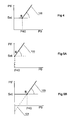
- Figures 4, 5A and 5B show by means of curve 100 the pressure relation induced via monitoring valve 10 to the load-sense circuit 6' by a pressure sensed in the sensing channel 9.
- the pressure of the sensing channel 9 is shown on the horizontal axis and the pressure of the load-sense circuit 6' is shown on the vertical axis.
- the minimum load-sense pressure i.e. the horizontal portion of the curve 100 is set.
- S The point where curve 100 changes from a constant pressure curve to a pressure ratio curve is marked with S in the figures.
- This point S shows the situation, where the sleeve 42 of the monitoring valve 10 begins to affect the pressure of the load-sense circuit 6'.
- the location of point S depends on how high the pressure in the reference channel 40 is.
- the pressure of the reference channel 40 is zero, so point S is on the vertical axis, and the corresponding curve can only cut the vertical axis at positive values.
- the dashed-line continuation 101 of the curve can cut the vertical axis at negative values.
- the location of the point S can be freely selected by adjusting the pressure of the reference channel 40, whereas the location of point S is strictly limited in prior-art valves to the position of Figure 5A.
- Figure 6 shows another construction of a monitoring valve 10 of the invention, and Figure 6A shows the according hydraulic graphical symbol.
- the monitoring valve 10 can be constructed in such a manner that the collar 23 of slide 20 is arranged to move in the front chamber 31 instead of the rear chamber 30.
- the sleeve 42 works by pushing the slide 20 to the opposite direction.
- the positions of the reference channel 40 and sensing channel 9 are reversed. When the pressure of the sensing channel 9 increases above the pressure of the reference channel 40, the sleeve 42 begins to reduce the force provided by the spring 12.
- Figure 6B shows by means of curve 102 the pressure relation induced via monitoring valve 10 in the load-sense circuit 6' by a pressure sensed in sensing channel 9. This is shown in Figure 6B by marking point S, where curve 102, i.e. the pressure of the load-sense circuit 6', begins to decrease.
- Figure 7 shows a side view of a rock drill 70.
- the monitoring system and monitoring valve 10 of the invention can be applied to control the hydraulic actuators of the rock drill 70.
- These actuators include a percussion apparatus 71 and a rotating apparatus 72.
- one actuator of the rock drill 70 is a feed apparatus 73, by means of which the drill is moved on the feed beam 74.
- the feed apparatus 73 can be a hydraulic cylinder or motor, for instance.
- Figure 8 shows a hydraulic diagram including the monitoring valve 10 to control a rock drill apparatus.
- This Figure 8 is almost similar to Figure 1, but the spool 3' with double outlet for an actuator acting in both directions is simplified into a similar spool with a single outlet suitable for the percussion apparatus 71.
- the percussion apparatus is controlled via monitoring valve 10 depending on pressure in sensing channel 9 connected to the feed actuator 73.
- the monitoring valve is set to provide a response as per Figure 4.
- the precise setting of point S is achieved by setting the reference channel 40 by any pressure device.
- a pressure-reducing valve 80 with additional relieving feature 81 is shown in Figure 8.
- the description of valve 80 cannot be exhaustive, as any kind of pressure valve can be used, including electric actuated valves such as solenoid controlled proportional valves or servo-valves, without being out of the scope of the present invention.
- relief valve 8 In an arrangement as per Figure 8, one only action on relief valve 8 influences directly the feed pressure, and simultaneously the percussion pressure via the monitoring valve 10.
- Figure 8 also shows an improvement.
- An adjustable restrictor 82 is included in the feed line between the spool 3 and feed actuator 73.
- the sensing channel 9 is directly connected to the feed actuator inlet, so that the monitoring valve 10 senses the precise feed pressure applied to the actuator.
- a compensator valve 5 controlled by a relief valve 8 creates a substantially constant feed pressure, and the restrictor 82 creates a pressure drop proportional to square of the flow consumed by the feed actuator.
- an increasing penetration rate of the rock drill affects the drilling parameters, at first in decreasing the pressure of the feed actuator 73.
- the monitoring valve 10 decreases the percussion pressure.
- the sensing channel 9 is not subject to any flow : this specific feature ensures that no leak flow or no load-sense flow can pollute the flow from restrictor 82 to the feed actuator 73.
- the valve arrangement as per Figure 8 is sensitive to penetration rate, and determines the feed pressure variation and the percussion pressure variation depending on the penetration rate.
- one only action on the relief valve 8 may simultaneously increase the feed and the percussion pressures with the correct pressure ratio.
- the two pressures had to be set separately.
- the increase of penetration rate decreases the actual feed pressure, and the percussion pressure decreases in a predetermined ratio with the feed pressure decrease.
- Figure 9 shows a second improvement.
- the load-sense circuit 6 is connected to two relief valves 83 and 84 in series, instead of one only relief valve 8 as in Figure 8.
- the reference channel 40 of the monitoring valve 10 is connected in-between the two relief valves 83 and 84.
- one only action on the relief valve 83 simultaneously acts on the feed pressure and the percussion pressure, as explained in the description of the previous Figure 8.
- one only action on the relief valve 83 simultaneously biases the feed pressure and the reference pressure on monitoring valve 10, thus keeping the pressure difference between the sensing line 9 and the reference line 40 at least substantially constant, and thus keeping the percussion pressure unaffected.
- the operator may have a possibility to adjust the valve 84, while the percussion pressure and its according feed pressure variation are purely controlled by the penetration rate.
- the operator can only fine-tune the feed pressure, but the operator has no influence on the percussion pressure.
- the percussion pressure is only controlled by the penetration rate, and the sensing of the penetration rate is not affected by the possible adjustment or the fine-tuning decided by the operator on the feed pressure.
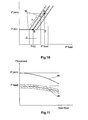
- Figure 10 illustrates the dual control of the feed pressure, with one only control affecting the percussion pressure.
- the horizontal axis shows the feed pressure and the vertical axis shows the percussion pressure.
- the minimum percussion pressure (min) is set with the spring 12 of the monitoring valve 10. If the feed pressure is lower than the pressure value P40 set by the relief valve 84, the percussion pressure stays constant at the minimum value. If the feed pressure is higher than the P40 threshold, any variation in the feed pressure induces a variation on the percussion pressure at a given ratio, and the oblique portion C of curve 90 shows this dependency.
- the oblique portion has a certain angular coefficient that corresponds to the pressure ratio of the monitoring valve 10.
- Figure 10 also illustrates that the system of the invention enables fine adjustment of the feed pressure without affecting the percussion pressure. Assuming that relief valve 83 is untouched, the triangle STU in Figure 10 stays constant. By varying the reference pressure by the relief valve 84, the triangle STU moves back and forth along arrow D. It is very easy to understand that the feed pressure can be variable, while the percussion pressure keeps constant. This fine adjustment of the feed pressure may be required to optimise the feed force for smaller or larger bits, for hemispherical or ballistic carbide buttons, for resharpened or worn out carbide buttons, and the like.
- Both Figures 10 and 11 illustrate that the drilling system equipped with restrictor 82 between the spool 3 and the feed actuator 73 is sensitive to the penetration rate, for example when drilling through soft rock or through a cavity.
- the feed apparatus 73 requires a higher flow of pressure fluid over the restrictor 82.
- the pressure drop caused by the restrictor 82 increases.
- the feed pressure decreases according to curve 95 of Figure 11.
- the monitoring valve 10 of the invention forces the percussion pressure to decrease according to curve 96.
- Figure 12 shows a partial hydraulic schematic of the rock drill 70. It includes all the features of Figure 9. In addition, several extra valves and restrictors create some auxiliary functions required by the complete drilling process.
- a solenoid valve 91 including a check-valve is connected as a by-pass to restrictor 82.
- the valve 91 allows fast feed retract motion, and fast feed forwards motion, for example when pulling rods.
- a second improvement is the solenoid valve 92, connected in a way to enable/disable the monitoring valve 10, so that the operator can override the pressure limitations induced by the monitoring valve 10. This function is for example required to rattle the drill string loose at maximum percussion pressure, but at zero feed pressure, before retrieving the string from the drilled hole.
- a third improvement is the introduction of two sensing channels 93 and 94 on both sides of the feed actuator 73, in order to activate the monitoring valve 10 in both feed directions.
- a fourth possible improvement is to form the restrictor 82 as a progressive slot on a spool, in order to decrease the area of the restrictor 82 in changing the longitudinal position of the spool.
- the spool position may also be biased by a spring and two hydraulic pressures applied to both ends, in order to limit the restrictor area while drilling through difficult rock.
Landscapes
- Engineering & Computer Science (AREA)
- Physics & Mathematics (AREA)
- Fluid Mechanics (AREA)
- Mechanical Engineering (AREA)
- General Engineering & Computer Science (AREA)
- Mining & Mineral Resources (AREA)
- Geology (AREA)
- Life Sciences & Earth Sciences (AREA)
- Environmental & Geological Engineering (AREA)
- General Life Sciences & Earth Sciences (AREA)
- Geochemistry & Mineralogy (AREA)
- Fluid-Pressure Circuits (AREA)
- Earth Drilling (AREA)
- Safety Valves (AREA)
- Perforating, Stamping-Out Or Severing By Means Other Than Cutting (AREA)
- Valve Device For Special Equipments (AREA)
Claims (14)
- Verfahren zum Steuern des Betriebs von mindestens einem ersten Hydraulikaktuator und einem zweiten Hydraulikaktuator, wobei das Verfahren umfasst:- Setzen des zu dem zweiten Aktuator gelenkten minimalen oder maximalen Drucks des Druckmediums mit einem Überwachungsventil (10),- Einstellen des zu dem zweiten Aktuator gelenkten Drucks des Druckmediums in einem vordefinierten Druckverhältnis mit dem zu dem ersten Aktuator gelenkten Druck,dadurch gekennzeichnet, dass ein zum Überwachungsventil (10) gelenkter Bezugsdruck gesteuert wird, um ein spezifisches Druckniveau des ersten Aktuators zu definieren, über welchem Niveau eine Druckverhältnissteuerung aktiv ist.
- Überwachungsventil, umfassend mindestens:einen Körper (26),ein langgestrecktes Gleitelement (20) mit einem ersten Ende und einem zweiten Ende und das zu einem Raum in dem Körper (26) angeordnet und in der Längsrichtung in dem Raum bewegbar ist,mindestens ein Kraftelement, das so angeordnet ist, dass es auf das erste Ende des Gleitelements (20) einwirkt, um das Gleitelement (20) in Richtung auf eine erste Bewegungsrichtung (B) zu bewegen, undmindestens einen steuerbaren Kanal (6'), der so angeordnet ist, dass er sich durch die Längsbewegung des Gleitelements (20) öffnet und schließt,dadurch gekennzeichnet, dass
das Gleitelement (20) mindestens einen Kragen (23) aufweist,
eine Hülse (42) um das Gleitelement (20) angeordnet ist,
der Körper (26) einen Raum aufweist, in dessem Innern der Kragen (23) und die Hülse (42) zur Bewegung angeordnet sind,
der äußere Rand der Hülse (42) dichtend am Körper (26) anliegt und der innere Rand der Hülse dichtend am Gleitelement (20) anliegt,
die Hülse (42) eine erste Kammer (31) und eine zweite Kammer (30) auf entgegengesetzten Seiten der Hülse (42) begrenzt und die Kammern (30, 31) nicht miteinander verbunden sind,
die erste Kammer (31) mindestens mit einem ersten Druckkanal verbunden ist,
die zweite Kammer (30) mindestens mit einem zweiten Druckkanal verbunden ist,
die Hülse (42) so angeordnet ist, dass sie sich abhängig vom Druckunterschied im Innern der Kammern (30, 31) in die erste (B) oder die zweite (A) Bewegungsrichtung bewegt, und
in einer Bewegungsrichtung die Hülse (42) so angeordnet ist, dass sie auf die axiale Position des Gleitelements (20) einwirkt, wenn sie am Kragen (23) anstößt. - Überwachungsventil nach Anspruch 2,
dadurch gekennzeichnet, dass
die Hülse (42) so angeordnet ist, dass sie auf derselben Seite wie das Kraftelement (12) am Kragen (23) anstößt,
sich die erste Kammer (31) auf der Kraftelement (12)-Seite der Hülse (42) befindet und sich die zweite Kammer (30) auf der Kragen (23)-Seite der Hülse befindet,
die erste Kammer (31) mit einem Sensorkanal (9) verbunden ist,
die zweite Kammer (30) mit einem Bezugskanal (40) verbunden ist,
die Hülse (42) so angeordnet ist, dass sie mittels des Kragens (23) das Gleitelement (20) in Richtung auf die erste Bewegungsrichtung (B) schiebt, wenn der Druck des Sensorkanals (9) höher als derjenige des Bezugskanals (40) ist. - Überwachungsventil nach Anspruch 2,
dadurch gekennzeichnet, dass
die Hülse (42) so angeordnet ist, dass sie auf der in Bezug zum Kraftelement (12) entgegengesetzten Seite des Kragens (23) am Kragen (23) anstößt,
sich die erste Kammer (31) auf der Kraftelement (12)-Seite der Hülse (42) befindet und sich die zweite Kammer (30) auf der entgegengesetzten Seite der Hülse (42) befindet,
die erste Kammer (31) mit einem Bezugskanal (40) verbunden ist,
die zweite Kammer (30) mit einem Sensorkanal (9) verbunden ist,
die Hülse (42) so angeordnet ist, dass sie mittels des Kragens (23) das Gleitelement (20) in Richtung auf die zweite Bewegungsrichtung (A) schiebt, wenn der Druck des Sensorkanals (9) höher als derjenige des Bezugskanals (40) ist. - Überwachungsventil nach einem der Ansprüche 2 oder 4,
dadurch gekennzeichnet, dass das Kraftelement eine Feder (12) ist und die Schubkraft der Feder (12) einstellbar ist. - Überwachungsventil nach einem der Ansprüche 2 bis 5,
dadurch gekennzeichnet, dass
das zweite Ende des Gleitelements (20) eng anliegend an eine Bohrung (27) im Körper (26) angeordnet ist,
der Druck des steuerbaren Kanals (6') so eingerichtet ist, dass er auf die Endoberfläche des zweiten Endes des Gleitelements (20) einwirkt,
die Bohrung (27) mit mindestens einem querlaufenden Austragkanal (11) verbunden ist, und
das zweite Ende des Gleitelements (20) angeordnet ist, um die Verbindung zwischen dem steuerbaren Kanal (6') und dem Austragkanal (11) zu öffnen und zu schließen. - Überwachungsventil nach einem der Ansprüche 2 bis 6,
dadurch gekennzeichnet, dass
das Überwachungsventil (10) angeordnet ist, um die Druckvariation des steuerbaren Kanals (6') in einem vordefinierten Verhältnis mit der Druckvariation des Sensorkanals (9) einzustellen, und
das Druckverhältnis des Überwachungsventils (10) durch das Verhältnis des Endflächeninhalts der Hülse (42) zu dem Quer-Flächeninhalt des zweiten Endes des Gleitelements (20) bestimmt ist. - Überwachungsventil nach Anspruch 3,
dadurch gekennzeichnet, dass die Wirkung der Hülse (42) eingerichtet ist, um den Druck des steuerbaren Kanals (6') bei einem vorgegebenen Verhältnis zu erhöhen, wenn die Hülse (42) auf derselben Seite wie das Kraftelement (12) an den Kragen (23) der Hülse (42) anstößt. - Überwachungsventil nach Anspruch 4,
dadurch gekennzeichnet, dass die Wirkung der Hülse (42) eingerichtet ist, um den Druck des steuerbaren Kanals (6') bei einem vorgegebenen Verhältnis zu verringern, wenn die Hülse (42) auf der entgegengesetzten Seite des Kraftelements (12) an den Kragen (23) der Hülse (42) anstößt. - Gesteinsbohrvorrichtung, umfassend mindestens:eine Schlagvorrichtung (71),eine Vorschubvorrichtung (73),ein Hydrauliksystem, mit dem die Schlagvorrichtung (71) und Vorschubvorrichtung (73) verbunden sind, und mindestens eine Hydraulikpumpe (1), um Hydraulikdruck zum Hydrauliksystem zu liefern,mindestens ein Kompensatorventil (5') im Druckmediumkanal, der zur Schlagvorrichtung (71) führt, und mindestens ein zweites Kompensatorventil (5) im Druckmediumkanal, der zur Vorschubvorrichtung (73) führt, um den Betrieb der Schlagvorrichtung bzw. Vorschubvorrichtung einzustellen, undmindestens ein Überwachungsventil (10), um den zur Schlagvorrichtung (71) gelenkten minimalen Druck des Druckmediums zu setzen und den zur Schlagvorrichtung (71) gelenkten Druck des Druckmediums in einem vordefinierten Druckverhältnis mit dem zur Vorschubvorrichtung (73) gelenkten Druck einzustellen,dadurch gekennzeichnet, dass
ein Bezugsdruckkanal (40) mit dem Überwachungsventil (10) verbunden ist, und die Steuerung des Drucks in dem Kanal so eingerichtet ist, dass ein spezifisches Druckniveau der Vorschubvorrichtung (73) bereitgestellt wird, über welchem Niveau der Vorschubdruck die Druckverhältnissteuerung bei der Schlagvorrichtung (71) aktiviert. - Gesteinsbohrvorrichtung, umfassend mindestens:eine Schlagvorrichtung (71),eine Vorschubvorrichtung (73),ein Hydrauliksystem, mit dem die Schlagvorrichtung (71) und Vorschubvorrichtung (73) verbunden sind, und mindestens eine Hydraulikpumpe (1), um Hydraulikdruck zum Hydrauliksystem zu liefern,mindestens ein Kompensatorventil (5) in dem zur Vorschubvorrichtung (73) führenden Druckmediumkanal, um den Betrieb der Vorschubvorrichtung einzustellen, undmindestens ein Überwachungsventil (10), um den zur Schlagvorrichtung (71) gelenkten minimalen Druck des Druckmediums zu setzen und um die zur Schlagvorrichtung (71) gelenkte Druckvariation des Druckmediums in einem vordefinierten Druckverhältnis mit der Druckvariation der Vorschubvorrichtung (73) einzustellen,dadurch gekennzeichnet, dass ein Bezugsdruckkanal (40) mit dem Überwachungsventil (10) verbunden ist und die Steuerung des Drucks in dem Kanal so eingerichtet ist, dass ein spezifisches Druckniveau der Vorschubvorrichtung (73) bereitgestellt wird, über welchem Niveau der Vorschubdruck die Druckverhältnissteuerung bei der Schlagvorrichtung (71) aktiviert.
- Gesteinsbohrvorrichtung nach Anspruch 10 oder 11,
dadurch gekennzeichnet, dass
der Druck der Vorschubvorrichtung (73) bestimmt ist, indem in dem Kraftmesskreis (6) der Vorschubvorrichtung (73) ein erstes Entlastungsventil (83) und ein zweites Entlastungsventil (84) gesetzt werden, die respektive in der Richtung des Kraftmessstroms montiert sind,
der Bezugskanal (40) des Überwachungsventils (10) zwischen dem ersten Entlastungsventil (83) und dem zweiten Entlastungsventil (84) verbunden ist,
das erste Entlastungsventil (83) in einem vordefinierten Druckverhältnis auf den Vorschubdruck und den Schlagdruck einwirkt, und
das zweite Entlastungsventil (84) nur auf den Vorschubdruck einwirkt. - Gesteinsbohrvorrichtung nach einem der Ansprüche 10 bis 12,
dadurch gekennzeichnet, dass
die Gesteinsbohrvorrichtung mindestens eine Drossel (82) umfasst, die auf den tatsächlichen Strom der Vorschubvorrichtung (73) empfindlich reagiert,
die Drossel (82) in dem Vorschubkreis zu der Vorschubvorrichtung (73) angeordnet ist und abhängig von der Eindringgeschwindigkeit eine Vorschubdruckvariation herbeiführt,
und die Vorschubdruckvariation gleichzeitig das Überwachungsventil (10) vorspannt, um die Druckvariation bei der Schlagvorrichtung (71) mit einem Druckverhältnis zu steuern. - Gesteinsbohrvorrichtung nach Anspruch 13,
dadurch gekennzeichnet, dass die Drossel (82) der Vorschubvorrichtung (73) auf einem Schieber gebildet ist, der durch eine Feder und Hydraulikdrücke auf beiden Enden vorgespannt ist, so dass der Drosselbereich hydraulisch gesteuert werden kann und von seinem voreingestellten Anfangswert hinab zu einem Null-Bereich zunehmend eingeschränkt wird, um in schwierigem Gestein zu bohren.
Applications Claiming Priority (3)
| Application Number | Priority Date | Filing Date | Title |
|---|---|---|---|
| FI20021980 | 2002-11-05 | ||
| FI20021980A FI119654B (fi) | 2002-11-05 | 2002-11-05 | Menetelmä ainakin kahden hydraulisen toimilaitteen toiminnan ohjaamiseksi, seurantaventtiili sekä edelleen kallionporauslaite |
| PCT/FI2003/000823 WO2004042192A1 (en) | 2002-11-05 | 2003-11-05 | Monitoring valve, rock drilling apparatus and a method for controlling at least two hydraulic actuators to such a monitoring valve and rock drilling apparatus |
Publications (2)
| Publication Number | Publication Date |
|---|---|
| EP1558835A1 EP1558835A1 (de) | 2005-08-03 |
| EP1558835B1 true EP1558835B1 (de) | 2007-06-06 |
Family
ID=8564889
Family Applications (1)
| Application Number | Title | Priority Date | Filing Date |
|---|---|---|---|
| EP03810473A Expired - Lifetime EP1558835B1 (de) | 2002-11-05 | 2003-11-05 | Überwachungsventil, gesteinsbohrvorrichtung und verfahren zur steuerung von mindestens zwei hydraulischen stellgliedern für ein solches überwachungsventil und eine solche gesteinsbohrvorrichtung |
Country Status (9)
| Country | Link |
|---|---|
| US (1) | US7124578B2 (de) |
| EP (1) | EP1558835B1 (de) |
| JP (1) | JP4388477B2 (de) |
| AT (1) | ATE364128T1 (de) |
| AU (1) | AU2003276294B2 (de) |
| DE (1) | DE60314272T2 (de) |
| FI (1) | FI119654B (de) |
| WO (1) | WO2004042192A1 (de) |
| ZA (2) | ZA200503537B (de) |
Families Citing this family (13)
| Publication number | Priority date | Publication date | Assignee | Title |
|---|---|---|---|---|
| FI115552B (fi) * | 2002-11-05 | 2005-05-31 | Sandvik Tamrock Oy | Järjestely kallioporauksen ohjaamiseksi |
| DE102005048156B9 (de) * | 2005-10-06 | 2010-08-12 | Dorma Gmbh + Co. Kg | Mobile Trennwand |
| FR2904446B1 (fr) * | 2006-07-28 | 2008-10-03 | Snecma Sa | Procede de detection et de quantification d'anomalies de percage |
| SE532483C2 (sv) * | 2007-04-11 | 2010-02-02 | Atlas Copco Rock Drills Ab | Metod, anordning och bergborrningsrigg för styrning av åtminstone en borrparameter |
| FI123634B (fi) * | 2007-10-05 | 2013-08-30 | Sandvik Mining & Constr Oy | Kallionrikkomislaite, suojaventtiili sekä menetelmä kallionrikkomislaitteen käyttämiseksi |
| KR20110076073A (ko) * | 2009-12-29 | 2011-07-06 | 볼보 컨스트럭션 이큅먼트 에이비 | 네가티브 컨트롤방식 유압시스템 |
| CN103950855B (zh) * | 2014-04-10 | 2014-12-31 | 中煤科工集团西安研究院有限公司 | 一种电液联控转臂限位装置 |
| US20160221171A1 (en) * | 2015-02-02 | 2016-08-04 | Caterpillar Inc. | Hydraulic hammer having dual valve acceleration control system |
| WO2018225102A1 (en) * | 2017-06-09 | 2018-12-13 | Buffo Salvatore | Safety valve for hydraulic systems |
| CN112648247B (zh) * | 2020-12-15 | 2023-02-24 | 陕西斯达防爆安全科技股份有限公司 | 一种合流逻辑复合作用液压阀组 |
| CN112727818B (zh) * | 2020-12-25 | 2023-03-21 | 中铁工程装备集团隧道设备制造有限公司 | 凿岩机的液压控制系统 |
| CN113638943B (zh) * | 2021-08-12 | 2024-06-14 | 中国铁建重工集团股份有限公司 | 一种冲击液压控制系统及凿岩台车 |
| CN116025330B (zh) * | 2022-12-14 | 2023-09-22 | 四川蓝海智能装备制造有限公司 | 一种防卡钎的电控式凿岩机液压控制结构及控制方法 |
Family Cites Families (15)
| Publication number | Priority date | Publication date | Assignee | Title |
|---|---|---|---|---|
| US3561542A (en) * | 1969-03-20 | 1971-02-09 | Gardner Denver Co | Control system for rock drills |
| US3823729A (en) * | 1973-05-07 | 1974-07-16 | Ltv Aerospace Corp | Differential pressure monitoring valve |
| US4484637A (en) * | 1979-01-19 | 1984-11-27 | Cooper Industries, Inc. | Positioning control system for rock drill support apparatus |
| US4431020A (en) * | 1981-10-08 | 1984-02-14 | Marotta Scientific Controls, Inc. | Flow-control system having a wide range of flow-rate control |
| US4516467A (en) * | 1983-05-27 | 1985-05-14 | Schroeder Brothers Corporation | Method and apparatus for controlling a rotary percussive hydraulic drill |
| FI67604C (fi) * | 1983-06-14 | 1985-04-10 | Tampella Oy Ab | Foerfarande och anordning foer reglering av matningsroerelsen hos en borrstaong vid bergborrning |
| US4967791A (en) * | 1989-04-26 | 1990-11-06 | The Boeing Company | Pressure activated check valve |
| JP3124094B2 (ja) * | 1991-12-25 | 2001-01-15 | カヤバ工業株式会社 | 複数アクチュエータの制御装置 |
| ZA932779B (en) * | 1993-04-21 | 1994-10-12 | Jarmo Uolevi Leppaenen | Control system for percussion drill |
| US5826613A (en) * | 1993-05-19 | 1998-10-27 | Georg Fischer Rohrleitungssysteme Ag | Flow control valve |
| FI95166C (fi) * | 1994-04-14 | 1995-12-27 | Tamrock Oy | Sovitelma painenestekäyttöisessä kallionporauslaitteessa |
| FR2756003B1 (fr) * | 1996-11-18 | 1998-12-24 | Montabert Ets | Dispositif de forage |
| ATE217564T1 (de) * | 1997-10-03 | 2002-06-15 | Sig Produktionstechnik Ag | Bohrhammer |
| US6408622B1 (en) * | 1998-12-28 | 2002-06-25 | Hitachi Construction Machinery Co., Ltd. | Hydraulic drive device |
| DE69935081T2 (de) | 1998-12-28 | 2007-11-15 | Furukawa Co. Ltd. | Drucksteuerventil |
-
2002
- 2002-11-05 FI FI20021980A patent/FI119654B/fi not_active IP Right Cessation
-
2003
- 2003-11-05 AU AU2003276294A patent/AU2003276294B2/en not_active Ceased
- 2003-11-05 JP JP2004549220A patent/JP4388477B2/ja not_active Expired - Fee Related
- 2003-11-05 EP EP03810473A patent/EP1558835B1/de not_active Expired - Lifetime
- 2003-11-05 DE DE60314272T patent/DE60314272T2/de not_active Expired - Lifetime
- 2003-11-05 WO PCT/FI2003/000823 patent/WO2004042192A1/en not_active Ceased
- 2003-11-05 AT AT03810473T patent/ATE364128T1/de not_active IP Right Cessation
- 2003-11-05 US US10/533,884 patent/US7124578B2/en not_active Expired - Fee Related
-
2005
- 2005-05-04 ZA ZA200503537A patent/ZA200503537B/en unknown
- 2005-05-04 ZA ZA200503536A patent/ZA200503536B/en unknown
Also Published As
| Publication number | Publication date |
|---|---|
| FI20021980A0 (fi) | 2002-11-05 |
| ATE364128T1 (de) | 2007-06-15 |
| DE60314272D1 (de) | 2007-07-19 |
| DE60314272T2 (de) | 2008-02-07 |
| FI20021980A7 (fi) | 2004-05-06 |
| US20060011360A1 (en) | 2006-01-19 |
| AU2003276294A1 (en) | 2004-06-07 |
| ZA200503537B (en) | 2006-08-30 |
| AU2003276294B2 (en) | 2008-05-08 |
| WO2004042192A1 (en) | 2004-05-21 |
| FI119654B (fi) | 2009-01-30 |
| US7124578B2 (en) | 2006-10-24 |
| JP4388477B2 (ja) | 2009-12-24 |
| ZA200503536B (en) | 2006-09-27 |
| EP1558835A1 (de) | 2005-08-03 |
| JP2006505752A (ja) | 2006-02-16 |
Similar Documents
| Publication | Publication Date | Title |
|---|---|---|
| EP1558835B1 (de) | Überwachungsventil, gesteinsbohrvorrichtung und verfahren zur steuerung von mindestens zwei hydraulischen stellgliedern für ein solches überwachungsventil und eine solche gesteinsbohrvorrichtung | |
| EP1558836B1 (de) | Anordnung zur gesteinsbohrungssteuerung | |
| US6334308B1 (en) | Pressure compensating valve, unloading pressure control valve and hydraulically operated device | |
| EP1701074B1 (de) | Druckbegrezungsventil mit Entlüftungsdämpfung | |
| US7387061B2 (en) | Control apparatus for hydraulic cylinder | |
| US5333449A (en) | Pressure compensating valve assembly | |
| EP0837249A1 (de) | Druckausgleichsventil | |
| JP2006505752A5 (de) | ||
| KR102342222B1 (ko) | 유량 조정 밸브 및 밸브 구조체 | |
| KR102078496B1 (ko) | 펌프 장치 | |
| JP3144914B2 (ja) | 油圧制御弁装置 | |
| EP0404956A1 (de) | Zufuhr von öl unter druck für den zylinder einer maschine | |
| US5735311A (en) | Pressure compensation valve | |
| US7243493B2 (en) | Valve gradually communicating a pressure signal | |
| US5562424A (en) | Pump displacement control for a variable displacement pump | |
| AU630914B2 (en) | Boring device | |
| JP2004360751A (ja) | 油圧制御装置 | |
| US7644646B1 (en) | Three position servo system to control the displacement of a hydraulic motor | |
| EP1821014B1 (de) | Entlüftungsventil | |
| US8511081B2 (en) | Hydraulic damping assembly and regulating system | |
| JP5217454B2 (ja) | 油圧駆動装置 | |
| EP0386263B1 (de) | Schnüffelventilanordnung | |
| JP3803147B2 (ja) | さく孔装置の打撃圧制御装置 | |
| JP2009174672A (ja) | 油圧駆動装置 |
Legal Events
| Date | Code | Title | Description |
|---|---|---|---|
| PUAI | Public reference made under article 153(3) epc to a published international application that has entered the european phase |
Free format text: ORIGINAL CODE: 0009012 |
|
| 17P | Request for examination filed |
Effective date: 20050429 |
|
| AK | Designated contracting states |
Kind code of ref document: A1 Designated state(s): AT BE BG CH CY CZ DE DK EE ES FI FR GB GR HU IE IT LI LU MC NL PT RO SE SI SK TR |
|
| AX | Request for extension of the european patent |
Extension state: AL LT LV MK |
|
| DAX | Request for extension of the european patent (deleted) | ||
| GRAP | Despatch of communication of intention to grant a patent |
Free format text: ORIGINAL CODE: EPIDOSNIGR1 |
|
| GRAS | Grant fee paid |
Free format text: ORIGINAL CODE: EPIDOSNIGR3 |
|
| GRAA | (expected) grant |
Free format text: ORIGINAL CODE: 0009210 |
|
| RAP1 | Party data changed (applicant data changed or rights of an application transferred) |
Owner name: SANDVIK MINING AND CONSTRUCTION OY |
|
| AK | Designated contracting states |
Kind code of ref document: B1 Designated state(s): AT BE BG CH CY CZ DE DK EE ES FI FR GB GR HU IE IT LI LU MC NL PT RO SE SI SK TR |
|
| PG25 | Lapsed in a contracting state [announced via postgrant information from national office to epo] |
Ref country code: CH Free format text: LAPSE BECAUSE OF FAILURE TO SUBMIT A TRANSLATION OF THE DESCRIPTION OR TO PAY THE FEE WITHIN THE PRESCRIBED TIME-LIMIT Effective date: 20070606 Ref country code: FI Free format text: LAPSE BECAUSE OF FAILURE TO SUBMIT A TRANSLATION OF THE DESCRIPTION OR TO PAY THE FEE WITHIN THE PRESCRIBED TIME-LIMIT Effective date: 20070606 Ref country code: LI Free format text: LAPSE BECAUSE OF FAILURE TO SUBMIT A TRANSLATION OF THE DESCRIPTION OR TO PAY THE FEE WITHIN THE PRESCRIBED TIME-LIMIT Effective date: 20070606 |
|
| REG | Reference to a national code |
Ref country code: GB Ref legal event code: FG4D |
|
| REG | Reference to a national code |
Ref country code: CH Ref legal event code: EP |
|
| REG | Reference to a national code |
Ref country code: IE Ref legal event code: FG4D |
|
| REF | Corresponds to: |
Ref document number: 60314272 Country of ref document: DE Date of ref document: 20070719 Kind code of ref document: P |
|
| PG25 | Lapsed in a contracting state [announced via postgrant information from national office to epo] |
Ref country code: ES Free format text: LAPSE BECAUSE OF FAILURE TO SUBMIT A TRANSLATION OF THE DESCRIPTION OR TO PAY THE FEE WITHIN THE PRESCRIBED TIME-LIMIT Effective date: 20070917 |
|
| ET | Fr: translation filed | ||
| REG | Reference to a national code |
Ref country code: SE Ref legal event code: TRGR |
|
| PG25 | Lapsed in a contracting state [announced via postgrant information from national office to epo] |
Ref country code: AT Free format text: LAPSE BECAUSE OF FAILURE TO SUBMIT A TRANSLATION OF THE DESCRIPTION OR TO PAY THE FEE WITHIN THE PRESCRIBED TIME-LIMIT Effective date: 20070606 |
|
| NLV1 | Nl: lapsed or annulled due to failure to fulfill the requirements of art. 29p and 29m of the patents act | ||
| REG | Reference to a national code |
Ref country code: CH Ref legal event code: PL |
|
| PG25 | Lapsed in a contracting state [announced via postgrant information from national office to epo] |
Ref country code: BE Free format text: LAPSE BECAUSE OF FAILURE TO SUBMIT A TRANSLATION OF THE DESCRIPTION OR TO PAY THE FEE WITHIN THE PRESCRIBED TIME-LIMIT Effective date: 20070606 |
|
| PG25 | Lapsed in a contracting state [announced via postgrant information from national office to epo] |
Ref country code: BG Free format text: LAPSE BECAUSE OF FAILURE TO SUBMIT A TRANSLATION OF THE DESCRIPTION OR TO PAY THE FEE WITHIN THE PRESCRIBED TIME-LIMIT Effective date: 20070906 Ref country code: CZ Free format text: LAPSE BECAUSE OF FAILURE TO SUBMIT A TRANSLATION OF THE DESCRIPTION OR TO PAY THE FEE WITHIN THE PRESCRIBED TIME-LIMIT Effective date: 20070606 Ref country code: SI Free format text: LAPSE BECAUSE OF FAILURE TO SUBMIT A TRANSLATION OF THE DESCRIPTION OR TO PAY THE FEE WITHIN THE PRESCRIBED TIME-LIMIT Effective date: 20070606 Ref country code: PT Free format text: LAPSE BECAUSE OF FAILURE TO SUBMIT A TRANSLATION OF THE DESCRIPTION OR TO PAY THE FEE WITHIN THE PRESCRIBED TIME-LIMIT Effective date: 20071106 Ref country code: NL Free format text: LAPSE BECAUSE OF FAILURE TO SUBMIT A TRANSLATION OF THE DESCRIPTION OR TO PAY THE FEE WITHIN THE PRESCRIBED TIME-LIMIT Effective date: 20070606 |
|
| PG25 | Lapsed in a contracting state [announced via postgrant information from national office to epo] |
Ref country code: SK Free format text: LAPSE BECAUSE OF FAILURE TO SUBMIT A TRANSLATION OF THE DESCRIPTION OR TO PAY THE FEE WITHIN THE PRESCRIBED TIME-LIMIT Effective date: 20070606 |
|
| PLBE | No opposition filed within time limit |
Free format text: ORIGINAL CODE: 0009261 |
|
| STAA | Information on the status of an ep patent application or granted ep patent |
Free format text: STATUS: NO OPPOSITION FILED WITHIN TIME LIMIT |
|
| PG25 | Lapsed in a contracting state [announced via postgrant information from national office to epo] |
Ref country code: IT Free format text: LAPSE BECAUSE OF FAILURE TO SUBMIT A TRANSLATION OF THE DESCRIPTION OR TO PAY THE FEE WITHIN THE PRESCRIBED TIME-LIMIT Effective date: 20070606 Ref country code: GR Free format text: LAPSE BECAUSE OF FAILURE TO SUBMIT A TRANSLATION OF THE DESCRIPTION OR TO PAY THE FEE WITHIN THE PRESCRIBED TIME-LIMIT Effective date: 20070907 Ref country code: DK Free format text: LAPSE BECAUSE OF FAILURE TO SUBMIT A TRANSLATION OF THE DESCRIPTION OR TO PAY THE FEE WITHIN THE PRESCRIBED TIME-LIMIT Effective date: 20070606 |
|
| 26N | No opposition filed |
Effective date: 20080307 |
|
| PG25 | Lapsed in a contracting state [announced via postgrant information from national office to epo] |
Ref country code: RO Free format text: LAPSE BECAUSE OF FAILURE TO SUBMIT A TRANSLATION OF THE DESCRIPTION OR TO PAY THE FEE WITHIN THE PRESCRIBED TIME-LIMIT Effective date: 20070606 |
|
| PG25 | Lapsed in a contracting state [announced via postgrant information from national office to epo] |
Ref country code: MC Free format text: LAPSE BECAUSE OF NON-PAYMENT OF DUE FEES Effective date: 20071130 |
|
| GBPC | Gb: european patent ceased through non-payment of renewal fee |
Effective date: 20071105 |
|
| PG25 | Lapsed in a contracting state [announced via postgrant information from national office to epo] |
Ref country code: IE Free format text: LAPSE BECAUSE OF NON-PAYMENT OF DUE FEES Effective date: 20071105 |
|
| PG25 | Lapsed in a contracting state [announced via postgrant information from national office to epo] |
Ref country code: GB Free format text: LAPSE BECAUSE OF NON-PAYMENT OF DUE FEES Effective date: 20071105 |
|
| PG25 | Lapsed in a contracting state [announced via postgrant information from national office to epo] |
Ref country code: EE Free format text: LAPSE BECAUSE OF FAILURE TO SUBMIT A TRANSLATION OF THE DESCRIPTION OR TO PAY THE FEE WITHIN THE PRESCRIBED TIME-LIMIT Effective date: 20070606 |
|
| PG25 | Lapsed in a contracting state [announced via postgrant information from national office to epo] |
Ref country code: CY Free format text: LAPSE BECAUSE OF FAILURE TO SUBMIT A TRANSLATION OF THE DESCRIPTION OR TO PAY THE FEE WITHIN THE PRESCRIBED TIME-LIMIT Effective date: 20070606 |
|
| PG25 | Lapsed in a contracting state [announced via postgrant information from national office to epo] |
Ref country code: LU Free format text: LAPSE BECAUSE OF NON-PAYMENT OF DUE FEES Effective date: 20071105 |
|
| PG25 | Lapsed in a contracting state [announced via postgrant information from national office to epo] |
Ref country code: HU Free format text: LAPSE BECAUSE OF FAILURE TO SUBMIT A TRANSLATION OF THE DESCRIPTION OR TO PAY THE FEE WITHIN THE PRESCRIBED TIME-LIMIT Effective date: 20071207 Ref country code: TR Free format text: LAPSE BECAUSE OF FAILURE TO SUBMIT A TRANSLATION OF THE DESCRIPTION OR TO PAY THE FEE WITHIN THE PRESCRIBED TIME-LIMIT Effective date: 20070606 |
|
| REG | Reference to a national code |
Ref country code: FR Ref legal event code: PLFP Year of fee payment: 13 |
|
| PGFP | Annual fee paid to national office [announced via postgrant information from national office to epo] |
Ref country code: DE Payment date: 20151028 Year of fee payment: 13 |
|
| PGFP | Annual fee paid to national office [announced via postgrant information from national office to epo] |
Ref country code: SE Payment date: 20151111 Year of fee payment: 13 |
|
| REG | Reference to a national code |
Ref country code: FR Ref legal event code: PLFP Year of fee payment: 14 |
|
| PGFP | Annual fee paid to national office [announced via postgrant information from national office to epo] |
Ref country code: FR Payment date: 20161014 Year of fee payment: 14 |
|
| REG | Reference to a national code |
Ref country code: DE Ref legal event code: R119 Ref document number: 60314272 Country of ref document: DE |
|
| REG | Reference to a national code |
Ref country code: SE Ref legal event code: EUG |
|
| PG25 | Lapsed in a contracting state [announced via postgrant information from national office to epo] |
Ref country code: SE Free format text: LAPSE BECAUSE OF NON-PAYMENT OF DUE FEES Effective date: 20161106 |
|
| PG25 | Lapsed in a contracting state [announced via postgrant information from national office to epo] |
Ref country code: DE Free format text: LAPSE BECAUSE OF NON-PAYMENT OF DUE FEES Effective date: 20170601 |
|
| REG | Reference to a national code |
Ref country code: FR Ref legal event code: ST Effective date: 20180731 |
|
| PG25 | Lapsed in a contracting state [announced via postgrant information from national office to epo] |
Ref country code: FR Free format text: LAPSE BECAUSE OF NON-PAYMENT OF DUE FEES Effective date: 20171130 |