EP1558150B1 - Device for determining the position of a knee-joint endoprosthesis - Google Patents
Device for determining the position of a knee-joint endoprosthesis Download PDFInfo
- Publication number
- EP1558150B1 EP1558150B1 EP02785363A EP02785363A EP1558150B1 EP 1558150 B1 EP1558150 B1 EP 1558150B1 EP 02785363 A EP02785363 A EP 02785363A EP 02785363 A EP02785363 A EP 02785363A EP 1558150 B1 EP1558150 B1 EP 1558150B1
- Authority
- EP
- European Patent Office
- Prior art keywords
- femur
- tibia
- knee
- tibial
- relative
- Prior art date
- Legal status (The legal status is an assumption and is not a legal conclusion. Google has not performed a legal analysis and makes no representation as to the accuracy of the status listed.)
- Expired - Lifetime
Links
Images


Classifications
-
- A—HUMAN NECESSITIES
- A61—MEDICAL OR VETERINARY SCIENCE; HYGIENE
- A61F—FILTERS IMPLANTABLE INTO BLOOD VESSELS; PROSTHESES; DEVICES PROVIDING PATENCY TO, OR PREVENTING COLLAPSING OF, TUBULAR STRUCTURES OF THE BODY, e.g. STENTS; ORTHOPAEDIC, NURSING OR CONTRACEPTIVE DEVICES; FOMENTATION; TREATMENT OR PROTECTION OF EYES OR EARS; BANDAGES, DRESSINGS OR ABSORBENT PADS; FIRST-AID KITS
- A61F2/00—Filters implantable into blood vessels; Prostheses, i.e. artificial substitutes or replacements for parts of the body; Appliances for connecting them with the body; Devices providing patency to, or preventing collapsing of, tubular structures of the body, e.g. stents
- A61F2/02—Prostheses implantable into the body
- A61F2/30—Joints
- A61F2/46—Special tools for implanting artificial joints
- A61F2/4657—Measuring instruments used for implanting artificial joints
-
- A—HUMAN NECESSITIES
- A61—MEDICAL OR VETERINARY SCIENCE; HYGIENE
- A61B—DIAGNOSIS; SURGERY; IDENTIFICATION
- A61B17/00—Surgical instruments, devices or methods
- A61B17/14—Surgical saws
- A61B17/15—Guides therefor
- A61B17/154—Guides therefor for preparing bone for knee prosthesis
- A61B17/155—Cutting femur
-
- A—HUMAN NECESSITIES
- A61—MEDICAL OR VETERINARY SCIENCE; HYGIENE
- A61B—DIAGNOSIS; SURGERY; IDENTIFICATION
- A61B34/00—Computer-aided surgery; Manipulators or robots specially adapted for use in surgery
- A61B34/20—Surgical navigation systems; Devices for tracking or guiding surgical instruments, e.g. for frameless stereotaxis
-
- A—HUMAN NECESSITIES
- A61—MEDICAL OR VETERINARY SCIENCE; HYGIENE
- A61B—DIAGNOSIS; SURGERY; IDENTIFICATION
- A61B5/00—Measuring for diagnostic purposes; Identification of persons
- A61B5/06—Devices, other than using radiation, for detecting or locating foreign bodies ; Determining position of diagnostic devices within or on the body of the patient
- A61B5/061—Determining position of a probe within the body employing means separate from the probe, e.g. sensing internal probe position employing impedance electrodes on the surface of the body
- A61B5/064—Determining position of a probe within the body employing means separate from the probe, e.g. sensing internal probe position employing impedance electrodes on the surface of the body using markers
-
- A—HUMAN NECESSITIES
- A61—MEDICAL OR VETERINARY SCIENCE; HYGIENE
- A61B—DIAGNOSIS; SURGERY; IDENTIFICATION
- A61B5/00—Measuring for diagnostic purposes; Identification of persons
- A61B5/103—Measuring devices for testing the shape, pattern, colour, size or movement of the body or parts thereof, for diagnostic purposes
-
- A—HUMAN NECESSITIES
- A61—MEDICAL OR VETERINARY SCIENCE; HYGIENE
- A61B—DIAGNOSIS; SURGERY; IDENTIFICATION
- A61B5/00—Measuring for diagnostic purposes; Identification of persons
- A61B5/45—For evaluating or diagnosing the musculoskeletal system or teeth
- A61B5/4528—Joints
-
- A—HUMAN NECESSITIES
- A61—MEDICAL OR VETERINARY SCIENCE; HYGIENE
- A61B—DIAGNOSIS; SURGERY; IDENTIFICATION
- A61B90/00—Instruments, implements or accessories specially adapted for surgery or diagnosis and not covered by any of the groups A61B1/00 - A61B50/00, e.g. for luxation treatment or for protecting wound edges
- A61B90/36—Image-producing devices or illumination devices not otherwise provided for
-
- G—PHYSICS
- G01—MEASURING; TESTING
- G01S—RADIO DIRECTION-FINDING; RADIO NAVIGATION; DETERMINING DISTANCE OR VELOCITY BY USE OF RADIO WAVES; LOCATING OR PRESENCE-DETECTING BY USE OF THE REFLECTION OR RERADIATION OF RADIO WAVES; ANALOGOUS ARRANGEMENTS USING OTHER WAVES
- G01S5/00—Position-fixing by co-ordinating two or more direction or position line determinations; Position-fixing by co-ordinating two or more distance determinations
- G01S5/18—Position-fixing by co-ordinating two or more direction or position line determinations; Position-fixing by co-ordinating two or more distance determinations using ultrasonic, sonic or infrasonic waves
- G01S5/186—Determination of attitude
-
- G—PHYSICS
- G06—COMPUTING OR CALCULATING; COUNTING
- G06T—IMAGE DATA PROCESSING OR GENERATION, IN GENERAL
- G06T7/00—Image analysis
- G06T7/70—Determining position or orientation of objects or cameras
- G06T7/73—Determining position or orientation of objects or cameras using feature-based methods
-
- A—HUMAN NECESSITIES
- A61—MEDICAL OR VETERINARY SCIENCE; HYGIENE
- A61B—DIAGNOSIS; SURGERY; IDENTIFICATION
- A61B17/00—Surgical instruments, devices or methods
- A61B17/02—Surgical instruments, devices or methods for holding wounds open, e.g. retractors; Tractors
- A61B17/025—Joint distractors
- A61B2017/0268—Joint distractors for the knee
-
- A—HUMAN NECESSITIES
- A61—MEDICAL OR VETERINARY SCIENCE; HYGIENE
- A61B—DIAGNOSIS; SURGERY; IDENTIFICATION
- A61B34/00—Computer-aided surgery; Manipulators or robots specially adapted for use in surgery
- A61B34/10—Computer-aided planning, simulation or modelling of surgical operations
- A61B2034/101—Computer-aided simulation of surgical operations
- A61B2034/102—Modelling of surgical devices, implants or prosthesis
-
- A—HUMAN NECESSITIES
- A61—MEDICAL OR VETERINARY SCIENCE; HYGIENE
- A61B—DIAGNOSIS; SURGERY; IDENTIFICATION
- A61B34/00—Computer-aided surgery; Manipulators or robots specially adapted for use in surgery
- A61B34/10—Computer-aided planning, simulation or modelling of surgical operations
- A61B2034/101—Computer-aided simulation of surgical operations
- A61B2034/105—Modelling of the patient, e.g. for ligaments or bones
-
- A—HUMAN NECESSITIES
- A61—MEDICAL OR VETERINARY SCIENCE; HYGIENE
- A61B—DIAGNOSIS; SURGERY; IDENTIFICATION
- A61B34/00—Computer-aided surgery; Manipulators or robots specially adapted for use in surgery
- A61B34/20—Surgical navigation systems; Devices for tracking or guiding surgical instruments, e.g. for frameless stereotaxis
- A61B2034/2046—Tracking techniques
- A61B2034/2055—Optical tracking systems
-
- A—HUMAN NECESSITIES
- A61—MEDICAL OR VETERINARY SCIENCE; HYGIENE
- A61B—DIAGNOSIS; SURGERY; IDENTIFICATION
- A61B34/00—Computer-aided surgery; Manipulators or robots specially adapted for use in surgery
- A61B34/20—Surgical navigation systems; Devices for tracking or guiding surgical instruments, e.g. for frameless stereotaxis
- A61B2034/2068—Surgical navigation systems; Devices for tracking or guiding surgical instruments, e.g. for frameless stereotaxis using pointers, e.g. pointers having reference marks for determining coordinates of body points
-
- A—HUMAN NECESSITIES
- A61—MEDICAL OR VETERINARY SCIENCE; HYGIENE
- A61B—DIAGNOSIS; SURGERY; IDENTIFICATION
- A61B34/00—Computer-aided surgery; Manipulators or robots specially adapted for use in surgery
- A61B34/20—Surgical navigation systems; Devices for tracking or guiding surgical instruments, e.g. for frameless stereotaxis
- A61B2034/2072—Reference field transducer attached to an instrument or patient
-
- A—HUMAN NECESSITIES
- A61—MEDICAL OR VETERINARY SCIENCE; HYGIENE
- A61B—DIAGNOSIS; SURGERY; IDENTIFICATION
- A61B90/00—Instruments, implements or accessories specially adapted for surgery or diagnosis and not covered by any of the groups A61B1/00 - A61B50/00, e.g. for luxation treatment or for protecting wound edges
- A61B90/06—Measuring instruments not otherwise provided for
- A61B2090/061—Measuring instruments not otherwise provided for for measuring dimensions, e.g. length
-
- A—HUMAN NECESSITIES
- A61—MEDICAL OR VETERINARY SCIENCE; HYGIENE
- A61B—DIAGNOSIS; SURGERY; IDENTIFICATION
- A61B90/00—Instruments, implements or accessories specially adapted for surgery or diagnosis and not covered by any of the groups A61B1/00 - A61B50/00, e.g. for luxation treatment or for protecting wound edges
- A61B90/06—Measuring instruments not otherwise provided for
- A61B2090/067—Measuring instruments not otherwise provided for for measuring angles
-
- A—HUMAN NECESSITIES
- A61—MEDICAL OR VETERINARY SCIENCE; HYGIENE
- A61B—DIAGNOSIS; SURGERY; IDENTIFICATION
- A61B5/00—Measuring for diagnostic purposes; Identification of persons
- A61B5/68—Arrangements of detecting, measuring or recording means, e.g. sensors, in relation to patient
- A61B5/6846—Arrangements of detecting, measuring or recording means, e.g. sensors, in relation to patient specially adapted to be brought in contact with an internal body part, i.e. invasive
- A61B5/6867—Arrangements of detecting, measuring or recording means, e.g. sensors, in relation to patient specially adapted to be brought in contact with an internal body part, i.e. invasive specially adapted to be attached or implanted in a specific body part
- A61B5/6878—Bone
-
- A—HUMAN NECESSITIES
- A61—MEDICAL OR VETERINARY SCIENCE; HYGIENE
- A61F—FILTERS IMPLANTABLE INTO BLOOD VESSELS; PROSTHESES; DEVICES PROVIDING PATENCY TO, OR PREVENTING COLLAPSING OF, TUBULAR STRUCTURES OF THE BODY, e.g. STENTS; ORTHOPAEDIC, NURSING OR CONTRACEPTIVE DEVICES; FOMENTATION; TREATMENT OR PROTECTION OF EYES OR EARS; BANDAGES, DRESSINGS OR ABSORBENT PADS; FIRST-AID KITS
- A61F2/00—Filters implantable into blood vessels; Prostheses, i.e. artificial substitutes or replacements for parts of the body; Appliances for connecting them with the body; Devices providing patency to, or preventing collapsing of, tubular structures of the body, e.g. stents
- A61F2/02—Prostheses implantable into the body
- A61F2/30—Joints
- A61F2/38—Joints for elbows or knees
- A61F2/3859—Femoral components
-
- A—HUMAN NECESSITIES
- A61—MEDICAL OR VETERINARY SCIENCE; HYGIENE
- A61F—FILTERS IMPLANTABLE INTO BLOOD VESSELS; PROSTHESES; DEVICES PROVIDING PATENCY TO, OR PREVENTING COLLAPSING OF, TUBULAR STRUCTURES OF THE BODY, e.g. STENTS; ORTHOPAEDIC, NURSING OR CONTRACEPTIVE DEVICES; FOMENTATION; TREATMENT OR PROTECTION OF EYES OR EARS; BANDAGES, DRESSINGS OR ABSORBENT PADS; FIRST-AID KITS
- A61F2/00—Filters implantable into blood vessels; Prostheses, i.e. artificial substitutes or replacements for parts of the body; Appliances for connecting them with the body; Devices providing patency to, or preventing collapsing of, tubular structures of the body, e.g. stents
- A61F2/02—Prostheses implantable into the body
- A61F2/30—Joints
- A61F2/38—Joints for elbows or knees
- A61F2/389—Tibial components
-
- A—HUMAN NECESSITIES
- A61—MEDICAL OR VETERINARY SCIENCE; HYGIENE
- A61F—FILTERS IMPLANTABLE INTO BLOOD VESSELS; PROSTHESES; DEVICES PROVIDING PATENCY TO, OR PREVENTING COLLAPSING OF, TUBULAR STRUCTURES OF THE BODY, e.g. STENTS; ORTHOPAEDIC, NURSING OR CONTRACEPTIVE DEVICES; FOMENTATION; TREATMENT OR PROTECTION OF EYES OR EARS; BANDAGES, DRESSINGS OR ABSORBENT PADS; FIRST-AID KITS
- A61F2/00—Filters implantable into blood vessels; Prostheses, i.e. artificial substitutes or replacements for parts of the body; Appliances for connecting them with the body; Devices providing patency to, or preventing collapsing of, tubular structures of the body, e.g. stents
- A61F2/02—Prostheses implantable into the body
- A61F2/30—Joints
- A61F2/46—Special tools for implanting artificial joints
- A61F2/4603—Special tools for implanting artificial joints for insertion or extraction of endoprosthetic joints or of accessories thereof
- A61F2/461—Special tools for implanting artificial joints for insertion or extraction of endoprosthetic joints or of accessories thereof of knees
-
- A—HUMAN NECESSITIES
- A61—MEDICAL OR VETERINARY SCIENCE; HYGIENE
- A61F—FILTERS IMPLANTABLE INTO BLOOD VESSELS; PROSTHESES; DEVICES PROVIDING PATENCY TO, OR PREVENTING COLLAPSING OF, TUBULAR STRUCTURES OF THE BODY, e.g. STENTS; ORTHOPAEDIC, NURSING OR CONTRACEPTIVE DEVICES; FOMENTATION; TREATMENT OR PROTECTION OF EYES OR EARS; BANDAGES, DRESSINGS OR ABSORBENT PADS; FIRST-AID KITS
- A61F2/00—Filters implantable into blood vessels; Prostheses, i.e. artificial substitutes or replacements for parts of the body; Appliances for connecting them with the body; Devices providing patency to, or preventing collapsing of, tubular structures of the body, e.g. stents
- A61F2/02—Prostheses implantable into the body
- A61F2/30—Joints
- A61F2/46—Special tools for implanting artificial joints
- A61F2002/4632—Special tools for implanting artificial joints using computer-controlled surgery, e.g. robotic surgery
-
- A—HUMAN NECESSITIES
- A61—MEDICAL OR VETERINARY SCIENCE; HYGIENE
- A61F—FILTERS IMPLANTABLE INTO BLOOD VESSELS; PROSTHESES; DEVICES PROVIDING PATENCY TO, OR PREVENTING COLLAPSING OF, TUBULAR STRUCTURES OF THE BODY, e.g. STENTS; ORTHOPAEDIC, NURSING OR CONTRACEPTIVE DEVICES; FOMENTATION; TREATMENT OR PROTECTION OF EYES OR EARS; BANDAGES, DRESSINGS OR ABSORBENT PADS; FIRST-AID KITS
- A61F2/00—Filters implantable into blood vessels; Prostheses, i.e. artificial substitutes or replacements for parts of the body; Appliances for connecting them with the body; Devices providing patency to, or preventing collapsing of, tubular structures of the body, e.g. stents
- A61F2/02—Prostheses implantable into the body
- A61F2/30—Joints
- A61F2/46—Special tools for implanting artificial joints
- A61F2/4657—Measuring instruments used for implanting artificial joints
- A61F2002/4658—Measuring instruments used for implanting artificial joints for measuring dimensions, e.g. length
-
- A—HUMAN NECESSITIES
- A61—MEDICAL OR VETERINARY SCIENCE; HYGIENE
- A61F—FILTERS IMPLANTABLE INTO BLOOD VESSELS; PROSTHESES; DEVICES PROVIDING PATENCY TO, OR PREVENTING COLLAPSING OF, TUBULAR STRUCTURES OF THE BODY, e.g. STENTS; ORTHOPAEDIC, NURSING OR CONTRACEPTIVE DEVICES; FOMENTATION; TREATMENT OR PROTECTION OF EYES OR EARS; BANDAGES, DRESSINGS OR ABSORBENT PADS; FIRST-AID KITS
- A61F2/00—Filters implantable into blood vessels; Prostheses, i.e. artificial substitutes or replacements for parts of the body; Appliances for connecting them with the body; Devices providing patency to, or preventing collapsing of, tubular structures of the body, e.g. stents
- A61F2/02—Prostheses implantable into the body
- A61F2/30—Joints
- A61F2/46—Special tools for implanting artificial joints
- A61F2/4657—Measuring instruments used for implanting artificial joints
- A61F2002/4668—Measuring instruments used for implanting artificial joints for measuring angles
-
- G—PHYSICS
- G06—COMPUTING OR CALCULATING; COUNTING
- G06T—IMAGE DATA PROCESSING OR GENERATION, IN GENERAL
- G06T2207/00—Indexing scheme for image analysis or image enhancement
- G06T2207/30—Subject of image; Context of image processing
- G06T2207/30004—Biomedical image processing
- G06T2207/30008—Bone
Definitions
- the invention relates to a system for determining the position of the tibial component and / or the femoral component of a knee joint endoprosthesis relative to the proximal tibial plateau or to the distal femur with a navigation system for monitoring the position of the femur and the tibia via marking elements which can be fixed thereto, with a distraction device which Laterally and medially, the distal femur and proximal tibial plateau are displaced laterally and medially with a defined force into a splayed position, with a data processing system showing the relative positions of the femur and tibia in this distraction and thus the size of the gap between the femur and tibia determines and calculates various virtual relative positions of the femur and tibia with the knee extended and flexed, depending on geometric data of the knee joint endoprosthesis and various assumed positions of the tibial component on the tibia and / or femoral
- endoprostheses which consist of two or three parts, for example, from a tibial fixable on the tibial component, fixable on the femur femoral part and arranged between the femoral part and tibial component intermediate part.
- Tibial component and femoral component must be connected to the tibia or femur so that the kinematics of the original knee joint are reproduced as well as possible.
- the tibial plateau and the femur must be resected by sawing, so that the tibial component and femoral component in the desired position on the tibia and femur come to rest, This position is responsible for the optimal kinematics of the knee joint.
- marking elements may for example be elements with a plurality of radiating transmitters, such as infrared diodes, in other cases are marking elements with a plurality of spaced-apart reflection bodies, e.g. reflect an infrared radiation well.
- the navigation system detects the radiation emanating from the marking element and can thereby determine the position of the marking element in space and thus also the position of the body part on which the marking element is fixed.
- Such navigation systems are regularly used in knee surgery to monitor the movement of the femur and tibia and also to anatomical geometric data of the femur and the tibia head by means of suitable navigated investment or tactile instruments to capture (DE 100 31 887 A1).
- a system for determining the position of the tibial component and / or the femoral component of a knee joint endoprosthesis relative to the proximal tibial plateau or to the distal femur with a navigation system for monitoring the position of the femur and the tibia via marking elements which can be fixed thereto Distraction device, which laterally and medially displaces the distal femur and the proximal tibial plateau with a defined force into a spread position with a defined force, with a data processing system that determines the relative positions of the femur and tibia during this distraction and thus the size of the gap between Femur and tibia are determined and dependent on geometric Data from the knee joint endoprosthesis and various assumed positions of the tibia on the tibia and / or the femoral femur calculate various relative virtual positions of the femur and tibia with the knee flexed and flexe
- the position of the tibial component and / or the femoral component can be determined without having to make any changes to the tibia or femur. It is sufficient to expose the knee joint and then determine by spreading the gap between the tibial plateau and femur with the knee extended and bent knee each adjusting relative position of the femur and tibia and thus the gap width between the tibial plateau and femur.
- certain positions on the tibia or femur are determined for the selected parts of the prosthesis. This is done only virtually, so not actually by contact surfaces are determined, where the prosthesis parts can be applied to the femur and tibia, such as sawing planes.
- This position data is therefore virtual, because in fact no prosthesis part is moved, but this movement is carried out by a pure calculation.
- the virtual position data for a particular assumed position of the prosthesis parts are then compared with the relative positions that have been recorded in the anatomical knee joint in the spread by means of the distraction device.
- Optimal reproduction of the body's kinematics can be achieved if, according to a preferred embodiment, a selected position is determined so that the virtual relative position of the femur and tibia coincides with the spread position. It then results in a sequence of movements that corresponds to the natural sequence of movements, wherein in the stretched and bent position, the tension of the ligaments is identical to the natural state.
- a selected position is determined so that the size of the gap between the femur and tibia in the angled position and / or the extended position of the knee laterally and medially is at least approximately equal.
- the position of the prosthesis parts can be assumed differently in many ways; for example, in a first preferred embodiment it is possible to shift the assumed position of the femoral part by its parallel displacement perpendicular to the longitudinal axis of the femur in order to calculate various virtual relative positions.
- the longitudinal axis of the femur may be identical to the mechanical axis of the femur connecting the knee joint to the hip joint. This different relative position corresponds to a different thickness of the articular surface resected at the distal end of the femur.
- the assumed position of the femoral component is displaced by its parallel displacement in the anterior-posterior direction. With such a displacement results in a change in distance of the dorsal articular surface of the femoral component, so that this articular surface has different distances to the tibial plateau with bent knee.
- the assumed position of the femoral component is changed by pivoting about an anterior-posterior axis in order to calculate various virtual relative positions.
- Pivoting leads to a correction of the varus-valgus position of the knee, which means that the width of the gap between the femur and the tibial component is changed laterally and medially, even with the knee extended.
- the assumed position of the femoral component is changed by pivoting about a medial-lateral axis. This leads to a tilt of the articular surfaces relative to the longitudinal axis of the femur and may be important for certain corrections.
- the ligamentous apparatus becomes progressively stiffer upon expansion and is practically unstretchable beyond a certain elongation, i. the distraction enters saturation.
- the achievable elongation in this area is relatively independent of the expansive force applied, and for this reason it is advantageous to distract into this area, thus giving well reproducible results.
- the actual gap between the gliding surfaces of the femur and the tibial plateau can only be accurately determined during flexion of the knee and distraction device if additional geometrical data on the shape of the femur and tibia are available , It is therefore provided according to a further development of the invention that, in order to determine the size of the gap between femur and tibia, the contour of the proximal tibial plateau and the contour of the distal femur are navigated through the system of at least one Investment element to these contours determined.
- a contact element has a stylus tip, are scanned with the various points of the contours.
- a contact element has a flat contact surface, which applies to the contour to be determined.
- a contact element has two mutually perpendicular contact surfaces, which applies together to the contour to be determined. This is advantageous, for example, for determining the contour of the condylar surfaces of the femur, the two abutment surfaces can then be applied to the distal condylar surface or the dorsal condylar surface so that information about the contours in this region can be obtained.
- the comparison of the spread position and each calculated by the simulation virtual relative position is preferably carried out with the aid of a viewing device or a display on the surgeon from this data derived information is displayed, for example, can be provided according to a preferred embodiment that one on a Display the size of the medial and lateral gap in the stretched and in the angled Position of the knee in each calculated virtual relative positions represents. For example, the surgeon may now change the assumed positions so that the size of the gap becomes equal medial and lateral and, if possible, in the extended and angled states.
- the position of the femoral component assumed for the determination of various virtual relative positions relative to geometric data of the femur for example to an image of the femur corresponding to the geometric data.
- the surgeon can then read off, for example, the inclination of a contact surface of the femoral component relative to the longitudinal axis of the femur or a similar measure directly and make a corresponding variation of the assumed position so that this read size corresponds to the ideas of the surgeon.
- the data processing system is associated with a display that displays the relative position of the femur and tibia in the distraction corresponding data and the virtual relative positions corresponding data for the purpose of their comparison.
- the data processing system on the display the size of the medial and lateral gap in the extended and in the angled position of the knee in each calculated virtual relative positions.
- the data processing system displays on the display the position of the femoral component assumed relative to the geometrical data of the femur for the determination of various virtual relative positions.
- such a device comprises at least one navigated abutment element, which can be applied to the contour of the proximal tibial plateau and the contour of the distal femur for determining the size of the gap between femur and tibia.
- a contact element has a Tastspitze, with the various points of the contours are scanned.
- a contact element has a flat contact surface which is applied to the contour to be determined.
- the contact element can have two mutually perpendicular abutment surfaces, which applies together to the contour to be determined.
- the patient 1 is mounted on an operating table 2, and the knee joint is opened in a conventional manner.
- At least on the femur 3 and on the tibia 4 and preferably also on the hip bone 5 and on the foot 6 of the patient marking elements 7, 8, 9 and 10 are fixed rigidly, for example by screwing a bone screw.
- Each of these marking elements carries three mutually spaced emitters 11, this can be active radiation emitter for ultrasonic radiation, infrared radiation or similar radiation or passive reflection elements for such radiation, which then reflect on them incident radiation and emit it.
- marking elements work together with a navigation system 12 having a plurality of radiation receivers 13, which detects the position and orientation of the marking elements in space and feeds this position corresponding data to a data processing system 14.
- the data processing system 14 is provided with a display 15 in the form of a screen and with a keyboard 16 for the input of additional data.
- the mechanical axes of the femur 3 and the tibia 4 are first determined.
- This mechanical axis of the femur 3 results for example from the connecting line of the hip joint 17 and the knee joint 18, these joints can be by means of the navigation system 12 in a conventional manner characterized determine that the femur and hip joint on the one hand and femur and tibia on the other hand are moved against each other, in the same way, the mechanical axis of the tibia can be determined as a connecting line of the ankle and knee joint by relative movement of the femur and tibia on the one hand and tibia and foot on the other.
- the marking elements which are rigidly connected to the femur, tibia, hip bone and foot are also moved on paths defined by the joints, and the data processing installation 14 can then determine the position of the joints relative to the marking elements and thus also to the body parts from these paths. with which the marking elements are firmly connected.
- a first operation step after determining the mechanical axes of the femur and tibia, the tibial plateau 19 is prepared, ie the proximal end of the tibia.
- the joint surface facing the femur 20, ie the distal end of the femur 3, is removed by a plane saw cut, the resulting sawing plane 21 is perpendicular to the previously determined mechanical axis of the tibia and is usually only a few millimeters below the proximal one End of tibial head 19.
- the exact location of the sawing plane 21 is again controlled by the fact that on the sawing plane 21, a plate-shaped contact element 22 is placed, which in turn is rigidly connected to a marker 23, so that the navigation system, the position of the contact element 22 in space and thus the location the sawing plane 21 can determine ( Figure 2).
- a distraction device 26 is inserted into the intermediate space between the sawing plane 21 of the tibial plateau 19, on the one hand, and the joint surfaces 24, 25 of the femur 20, which run side by side and at a distance from one another.
- This has two relatively displaceable spreading members 27, 28, a lower web-shaped spreading member 27 is applied to the sawing plane 21, an upper parallel extending spreading member 28 to one of the two joint surfaces 24, 25.
- a separate Distraction device 26 applied so that when spreading the two spreading members 27, 28 of a distraction device 26 each one or the other articular surface 24 and 25 can be removed from the sawing plane 21.
- the construction of the distraction device can be very different, there are distraction devices of this kind in large numbers, it is only important that it succeeds by moving the spreading members 27, 28 against each other, for example by means of an attacking them, shown in Figure 5 only very schematically Sp Schwarzinstrumentes 29, the gap between articular surfaces 24, 25 on the one hand and sawing plane 21 on the other hand to enlarge.
- the sidebands have an approximately elastic behavior at the beginning of the stretching, However, the elasticity reaches a saturation value, so that when applying a force exceeding a certain value in each case, a maximum elongation of the sidebands can be achieved and thus a maximum gap between the femur on the one hand and Tibiakopf on the other.
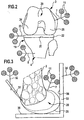
- this maximum gap 30 is shown schematically in an angled knee, in Figure 7 in a stretched.
- the gap width is defined by the distance of the two articular surfaces 24, 25 of the femur 3 from the sawing plane 21.
- the gap width at both articular surfaces 24, 25 about the same, but this must not be so, it can due to misalignments or adhesions quite different gap widths in the two articular surfaces 24, 25 give, both in angled knee and in the extended knee.
- the relative position of the femur and the tibia, which occupy this both in angled and in the extended knee after spreading the distraction 26, are determined by the navigation system 12 and the data processing system 14 corresponding records are stored, so these represent the kinematics of the knee joint to be replaced , the gap widths thus obtained provide information about the tension of the two sidebands.
- geometric data about the shape of the femur are needed.
- This data can be achieved with the help of navigated investment elements, ie investment elements, which are each provided with a marking element.
- a contact element may for example be a stylus tip 31 with a marking element 32 (FIG. 3), with this stylus tip 31 the contours of the femur 20 can be determined pointwise.
- Another abutment element is formed by an L-profile 33 with a marking element 34.
- the L-profile has on its inside two perpendicular to each other, flat contact surfaces 35, 36 which can be applied for example so at the distal or dorsal end of the femur that abutting the distal end bearing surface 35 perpendicular to the previously determined mechanical axis of the femur 3 is ( Figure 3). In this way, the extension of the articular surfaces 24 and 25 of the femur 3 can be determined.
- the next step is to simulate the movements that would occur in the knee joint when implanting an endograft prosthesis of a particular geometry in certain presumed positions.
- a specific type of knee joint endoprosthesis for example a tibial component, an intermediate part and a femoral component
- the dimensions of these parts are known, as well as the relative movements of the parts of this endoprosthesis relative to each other, which can be determined due to the geometric configuration of Endogelenkproothese.
- This data is entered in the form of a data set, for example via the keyboard 16 in the data processing system.
- the position of the femoral component relative to the femur can be varied, for example, by positioning the femoral component differently in the direction of the mechanical axis of the femur (Figure 9); it is possible for the femoral component to be inclined relative to the femur, for example anterior-posterior 10) or about a medial-laterally extending central axis (FIG. 11), the femoral component can also be displaced in the anterior-posterior direction (FIG. 12). This leads to a corresponding change of contact surfaces of the femoral component on the appropriately prepared femur, this is shown in the figures 9 to 12 by dotted lines showing different positions of these contact surfaces.
- the data processing system 14 may calculate the relative position of the femur and tibia with the knee extended and angled, and thus, e.g. Also, the width of the gap 30 in the extended and angled knee on the medial and lateral joint surface.
- the surgeon thus has the possibility of assuming different relative positions of the femoral component relative to the femur and with this assumed position to calculate the effects on the positioning of the femur and tibia relative to each other and thus, for example, the widths of the gap 30 for a specific assumed position of the femoral component relative to the femur.
- the plane defined by the sawing template can define, for example, the distal sawing surface of the femur; this defined sawing plane can be displaced or pivoted relative to the femur by adjusting the sawing template.
- this assumed sawing plane can be determined spatially, i.
- the navigation system determines the location of this assumed sawing plane relative to the femur.
- the gap widths in the form of rectangles are shown side by side, on one side for the medial articular surface and on the other side for the lateral articular surface, in both cases for angled and for a stretched knee.
- the extended position is characterized by symbols 37, the gap width by vertical bars 38, whose height corresponds to the gap width. This amount is additionally indicated in numbers.
- an image of the femur may be displayed on the display 15, in which the position of the assumed sawing plane is superimposed, so that the user can immediately recognize how this assumed sawing plane is arranged relative to the femur. This is particularly important if this sawing plane is inclined, the angle of inclination with respect to a perpendicular to the mechanical axis of the femur surface can then be read immediately. Thus, the surgeon can also check which assumed positions he selects, for example, to achieve a varus valgus correction.
- the widths of the lateral and medial articular surface slits 30 for both the extended and angled knees will appear on the display without delay that any movement of the knee would be necessary.
- the gap widths achieved in this way can now be compared by the surgeon with the gap widths which he wishes to achieve, be it that these gap widths correspond exactly to the gap widths which he previously determined in the patient's own knee with the aid of the distraction device 26, be He wants to deviate from these values in a well-defined way, for example, to align different medial and lateral gap widths.
- the surgeon can also check for side-band tensing effects that result from correcting certain malposition of the knee, such as a varus valgus malalignment. He can thus conclude a compromise between position correction on the one hand and intervention in the tension behavior of the sidebands on the other hand and determine the optimal position of the femoral component relative to the femur in advance, without the femur would have to be edited in any way.
- the surgeon also has the opportunity to perform this procedure for an endoprosthesis with different dimensions or different kinematic behavior, also resulting in different movements of the femur and tibia relative to each other.
- the data processing system 14 it is additionally possible to also simulate different prosthesis parts and their effects on the movement sequence so that, on the one hand, the selection of the prosthesis parts and, on the other hand, the assumed position of the prosthesis parts relative to the femur and / or or tibia the entire expected movement sequence can be simulated and compared with the desired results.
- a corresponding cut can be made on the femur with the aid of the sawing template, for example the distal sawing surface is formed, then further sawing surfaces follow, for example a dorsal sawing surface which is perpendicular to the distal one Sawing surface stands.
- Their position is determined in a very similar way by assuming different positions of this sawing surface and then calculating the effect of the different positioning on the kinematics. For example, the displacement of the dorsal cutting plane results in the femoral component being positioned differently relative to the femur in the anterior-posterior direction.
- FIG. 13 shows diagrammatically how the tibial component 40, intermediate part 41 and femoral component 42 of the knee dynasty prosthesis are arranged on the tibia and femur after implantation. It is also schematically shown in this illustration how tibia and femur are tensioned against each other by lateral bands 39.
Landscapes
- Health & Medical Sciences (AREA)
- Life Sciences & Earth Sciences (AREA)
- Engineering & Computer Science (AREA)
- Surgery (AREA)
- Veterinary Medicine (AREA)
- Animal Behavior & Ethology (AREA)
- Public Health (AREA)
- General Health & Medical Sciences (AREA)
- Biomedical Technology (AREA)
- Heart & Thoracic Surgery (AREA)
- Medical Informatics (AREA)
- Molecular Biology (AREA)
- Oral & Maxillofacial Surgery (AREA)
- Physics & Mathematics (AREA)
- Pathology (AREA)
- Nuclear Medicine, Radiotherapy & Molecular Imaging (AREA)
- Biophysics (AREA)
- Orthopedic Medicine & Surgery (AREA)
- Transplantation (AREA)
- Dentistry (AREA)
- General Physics & Mathematics (AREA)
- Physical Education & Sports Medicine (AREA)
- Human Computer Interaction (AREA)
- Robotics (AREA)
- Radar, Positioning & Navigation (AREA)
- Remote Sensing (AREA)
- Rheumatology (AREA)
- Cardiology (AREA)
- Vascular Medicine (AREA)
- Computer Vision & Pattern Recognition (AREA)
- Theoretical Computer Science (AREA)
- Prostheses (AREA)
- Surgical Instruments (AREA)
- Apparatus For Radiation Diagnosis (AREA)
Abstract
Description
Die Erfindung betrifft ein System zur Bestimmung der Lage des Tibiateils und/oder des Femurteils einer Kniegelenkendoprothese relativ zum proximalen Tibiakopf bzw. zum distalen Femur mit einem Navigationssystem zur Überwachung der Lage des Femurs und der Tibia über an diesen festlegbare Markierelemente, mit einem Distraktionsgerät, welches den distalen Femur und den proximalen Tibiakopf bei gestrecktem und bei abgewinkeltem Knie lateral und medial mit einer definierten Kraft in eine gespreizte Position verschiebt, mit einer Datenverarbeitungsanlage, die die Relativpositionen von Femur und Tibia bei dieser Distraktion und damit die Größe des Spaltes zwischen Femur und Tibia bestimmt und die in Abhängigkeit von geometrischen Daten der Kniegelenkendoprothese und verschiedenen angenommenen Positionen des Tibiateils an der Tibia und/oder des Femurteils am Femur verschiedene virtuelle Relativpositionen von Femur und Tibia bei gestrecktem und gebeugtem Knie berechnet.The invention relates to a system for determining the position of the tibial component and / or the femoral component of a knee joint endoprosthesis relative to the proximal tibial plateau or to the distal femur with a navigation system for monitoring the position of the femur and the tibia via marking elements which can be fixed thereto, with a distraction device which Laterally and medially, the distal femur and proximal tibial plateau are displaced laterally and medially with a defined force into a splayed position, with a data processing system showing the relative positions of the femur and tibia in this distraction and thus the size of the gap between the femur and tibia determines and calculates various virtual relative positions of the femur and tibia with the knee extended and flexed, depending on geometric data of the knee joint endoprosthesis and various assumed positions of the tibial component on the tibia and / or femoral component on the femur.
Bei der Implantatation einer Kniegelenkendoprothese werden häufig Endoprothesen verwendet, die aus zwei oder drei Teilen bestehen, beispielsweise aus einem an der Tibia festlegbaren Tibiateil, einem am Femur festlegbaren Femurteil und einem zwischen Femurteil und Tibiateil angeordneten Zwischenteil. Tibiateil und Femurteil müssen mit der Tibia bzw. dem Femur so verbunden werden, daß die Kinematik des ursprünglichen Kniegelenks möglichst gut reproduziert wird. Um dies zu erreichen, müssen der Tibiakopf und der Femur durch Sägeschnitte entsprechend reseziert werden, so daß Tibiateil und Femurteil in der gewünschten Position an Tibia und Femur zur Anlage kommen, diese Anlageposition ist verantwortlich für die optimale Kinematik des Kniegelenks.In the implantation of a knee joint endoprosthesis endoprostheses are often used, which consist of two or three parts, for example, from a tibial fixable on the tibial component, fixable on the femur femoral part and arranged between the femoral part and tibial component intermediate part. Tibial component and femoral component must be connected to the tibia or femur so that the kinematics of the original knee joint are reproduced as well as possible. To achieve this, the tibial plateau and the femur must be resected by sawing, so that the tibial component and femoral component in the desired position on the tibia and femur come to rest, This position is responsible for the optimal kinematics of the knee joint.
Es ist bekannt, zur Implantatation eines Kniegelenkes die ursprüngliche Kinematik des Knies und auch die Kinematik des Knies nach der Implantatation der Endoprothese dadurch zu überwachen, daß sowohl der Femur als auch die Tibia durch ein an sich bekanntes Navigationssystem lageüberwacht werden. Ein solches Navigationssystem kann die Position bestimmter Markierelemente im Raum laufend bestimmen, bei den Markierelementen kann es sich beispielsweise um Elemente mit mehreren strahlenden Sendern handeln, etwa Infrarotdioden, in anderen Fällen handelt es sich dabei um Markierelemente mit mehreren im Abstand zueinander angeordneten Reflexionskörpern, die z.B. eine Infrarotstrahlung gut reflektieren. Das Navigationssystem erfaßt die Strahlung, die von dem Markierelement ausgeht, und kann dadurch die Lage des Markierelementes im Raum bestimmen und damit auch die Lage des Körperteils, an dem das Markierelement festgelegt ist. Derartige Navigationssysteme werden bei Knieoperationen regelmäßig eingesetzt, um den Bewegungsablauf von Femur und Tibia zu überwachen und auch um anatomischgeometrische Daten des Femurs und des Tibiakopfes mittels geeigneter navigierter Anlage- oder Tastinstrumente zu erfassen (DE 100 31 887 A1).It is known to monitor the implantation of a knee joint, the original kinematics of the knee and the kinematics of the knee after implantation of the endoprosthesis characterized in that both the femur and the tibia are monitored by a known per se navigation system. Such a navigation system may continuously determine the position of certain marking elements in space, the marking elements may for example be elements with a plurality of radiating transmitters, such as infrared diodes, in other cases are marking elements with a plurality of spaced-apart reflection bodies, e.g. reflect an infrared radiation well. The navigation system detects the radiation emanating from the marking element and can thereby determine the position of the marking element in space and thus also the position of the body part on which the marking element is fixed. Such navigation systems are regularly used in knee surgery to monitor the movement of the femur and tibia and also to anatomical geometric data of the femur and the tibia head by means of suitable navigated investment or tactile instruments to capture (DE 100 31 887 A1).
Für das Gelingen einer Knieoperation ist wichtig, daß nach dem Einsetzen des Implantates Femur und Tibia auf der lateralen und medialen Seite gleichmäßig durch die Femur und Tibia verbindenden Bänder gegeneinander gespannt werden, und zwar möglichst sowohl in der gestreckten als auch in der abgewinkelten Stellung des Beines. Um dies zu erreichen ist es bekannt, Probeimplantate einzusetzen und nach dem Einsetzen der Probeimplantate die sich für diese Probeimplantate ergebenden Spannungen zu messen, beispielsweise mit Hilfe eines Distraktionsgerätes, welches die zusammenhaltenden Kräfte durch Aufspreizen des Spaltes zwischen Femur und Tibia mißt.For successful knee surgery, it is important that the femur and tibia on the lateral and medial side are evenly stretched against each other after insertion of the implant through the femoral and tibial ligaments, preferably both in the extended and angled positions of the leg , In order to achieve this, it is known to use trial implants and after insertion of the trial implants for this Measure tensions resulting trial implants, for example, using a distraction device, which measures the cohesive forces by spreading the gap between the femur and tibia.
Dieses Verfahren ist außerordentlich umständlich und birgt die Gefahr in sich, daß aufgrund von Fehlmessungen nach erfolgter Operation doch nicht die erwünschten Spannungsverhältnisse erreicht werden, dies kann dazu führen, daß die Gelenkflächen nach der Operation zu wenig oder aber umgekehrt auch zu stark gegeneinander gespannt werden.This method is extremely cumbersome and involves the risk that due to incorrect measurements after the operation but not the desired voltage ratios are achieved, this can cause the articular surfaces are too little or too strong and vice versa stretched against each other after surgery.
Es ist Aufgabe der Erfindung, ein System der gattungsgemäßen Art so auszubilden, daß während des Operationsablaufes und ohne Veränderungen an dem ursprünglichen Kniegelenk vorzunehmen, bestimmt werden kann, wie die Teile der Endoprothese zu implantieren sind, um die natürlichen Spannungsverhältnisse im Kniegelenk in der gewünschten Weise zu reproduzieren oder gegebenenfalls auch abzuwandeln.It is an object of the invention to design a system of the generic type so that it can be determined during the course of the operation and without making changes to the original knee joint, as to how the parts of the endoprosthesis are to be implanted, to the natural stress conditions in the knee joint in the desired manner to reproduce or modify if necessary.
Diese Aufgabe wird erfindungsgemäß gelöst durch ein System zur Bestimmung der Lage des Tibiateiles und/oder des Femurteils einer Kniegelenkendoprothese relativ zum proximalen Tibiakopf bzw. zum distalen Femur mit einem Navigationssystem zur Überwachung der Lage des Femurs und der Tibia über an diesen festlegbare Markierelemente, mit einem Distraktionsgerät, welches den distalen Femur und den proximalen Tibiakopf bei gestrecktem und bei abgewinkeltem Knie lateral und medial mit einer definierten Kraft in eine gespreizte Position verschiebt, mit einer Datenverarbeitungsanlage, die die Relativpositionen von Femur und Tibia bei dieser Distraktion und damit die Größe des Spaltes zwischen Femur und Tibia bestimmt und die in Abhängigkeit von geometrischen Daten der Kniegelenkendoprothese und verschiedenen angenommenen Positionen des Tibiateils an der Tibia und/oder des Femurteils am Femur verschiedene virtuelle Relativpositionen von Femur und Tibia bei gestrecktem und gebeugtem Knie berechnet.This object is achieved according to the invention by a system for determining the position of the tibial component and / or the femoral component of a knee joint endoprosthesis relative to the proximal tibial plateau or to the distal femur with a navigation system for monitoring the position of the femur and the tibia via marking elements which can be fixed thereto Distraction device, which laterally and medially displaces the distal femur and the proximal tibial plateau with a defined force into a spread position with a defined force, with a data processing system that determines the relative positions of the femur and tibia during this distraction and thus the size of the gap between Femur and tibia are determined and dependent on geometric Data from the knee joint endoprosthesis and various assumed positions of the tibia on the tibia and / or the femoral femur calculate various relative virtual positions of the femur and tibia with the knee flexed and flexed.
Mit diesem System kann damit die Lage des Tibiateils und/oder des Femurteils bestimmt werden, ohne daß an Tibia oder Femur Veränderungen vorgenommen werden müssen. Es genügt, das Kniegelenk freizulegen und dann durch Aufspreizen des Spaltes zwischen Tibiakopf und Femur bei gestrecktem Knie und bei abgebeugtem Knie die jeweils sich einstellende Relativposition von Femur und Tibia und damit die Spaltbreite zwischen Tibiakopf und Femur zu bestimmen. In einem nächsten Schritt werden für die ausgewählten Prothesenteile bestimmte Positionen an der Tibia bzw. am Femur festgelegt. Dies erfolgt nur virtuell, also nicht tatsächlich, indem Anlageflächen bestimmt werden, an denen die Prothesenteile an Femur und Tibia angelegt werden können, beispielsweise Sägeebenen.With this system, the position of the tibial component and / or the femoral component can be determined without having to make any changes to the tibia or femur. It is sufficient to expose the knee joint and then determine by spreading the gap between the tibial plateau and femur with the knee extended and bent knee each adjusting relative position of the femur and tibia and thus the gap width between the tibial plateau and femur. In a next step, certain positions on the tibia or femur are determined for the selected parts of the prosthesis. This is done only virtually, so not actually by contact surfaces are determined, where the prosthesis parts can be applied to the femur and tibia, such as sawing planes.
Mit den so angenommenen Anlageflächen und damit den so angenommenen Positionen der Implantatteile an Femur und/oder Tibia kann dann berechnet werden, wie sich Femur und Tibia bei der Beugebewegung relativ zueinander bewegen, sofern bei dieser Berechnung die geometrischen Daten der Implantatteile zugrunde gelegt werden. Diese geometrischen Daten geben an, wie die Implantatteile sich relativ zueinander bewegen, und aus den angenommenen Positionen der Implantatteile an Femur und Tibia einerseits und der Relativbewegung der Implantate zueinander andererseits lassen sich die virtuellen Relativpositionen von Femur und Tibia während der Beugebewegung berechnen.With the thus assumed contact surfaces and thus the assumed positions of the implant parts on the femur and / or tibia, it can then be calculated how the femur and tibia move relative to one another during the flexion movement, provided that the geometric data of the implant parts are used in this calculation. These geometric data indicate how the implant parts move relative to one another and from the assumed positions of the implant parts on the femur and tibia on the one hand and the relative movement of the implants on the other hand, the virtual relative positions of the femur and tibia can be calculated during the flexion movement.
Diese Positionsdaten sind deswegen virtuell, weil tatsächlich kein Prothesenteil bewegt wird, sondern diese Bewegung erfolgt durch eine reine Berechnung.This position data is therefore virtual, because in fact no prosthesis part is moved, but this movement is carried out by a pure calculation.
Die virtuellen Positionsdaten für eine bestimmte angenommene Position der Prothesenteile werden anschließend verglichen mit den Relativpositionen, die bei dem anatomischen Kniegelenk bei der Aufspreizung mit Hilfe des Distraktionsgerätes aufgenommen worden sind.The virtual position data for a particular assumed position of the prosthesis parts are then compared with the relative positions that have been recorded in the anatomical knee joint in the spread by means of the distraction device.
Eine optimale Reproduktion der körpereigenen Kinematik läßt sich dann erreichen, wenn gemäß einer bevorzugten Ausführungsform eine ausgewählte Position so bestimmt wird, daß die virtuelle Relativposition von Femur und Tibia mit der gespreizten Position übereinstimmt. Es ergibt sich dann ein Bewegungsablauf, der dem natürlichen Bewegungsablauf entspricht, wobei in gestreckter und in gebeugter Stellung die Spannung des Bandapparates identisch mit dem natürlichen Zustand ist.Optimal reproduction of the body's kinematics can be achieved if, according to a preferred embodiment, a selected position is determined so that the virtual relative position of the femur and tibia coincides with the spread position. It then results in a sequence of movements that corresponds to the natural sequence of movements, wherein in the stretched and bent position, the tension of the ligaments is identical to the natural state.
Es ist aber natürlich auch möglich, daß der Operateur gezielt eine Abweichung der virtuellen Relativposition von der tatsächlichen Relativposition wünscht, beispielsweise zur Korrektur einer Fehlstellung. Dann besteht die Möglichkeit, durch Variation der angenommenen Position der Implantatteile solange virtuelle Relativpositionen zu errechnen, bis eine virtuelle Relativposition gefunden ist, die der gewünschten Abweichung von der tatsächlichen Relativposition entspricht, mit anderen Worten wird die Bewegung des Knies auf diese Weise in Abhängigkeit von unterschiedlich angenommen Positionen der Prothesenteile simuliert, ohne daß dazu eine Bearbeitung des Tibiakopfes oder des Femurs notwendig wäre.But it is of course also possible that the surgeon specifically wants a deviation of the virtual relative position of the actual relative position, for example, to correct a malposition. Then, by varying the assumed position of the implant parts, it is possible to calculate virtual relative positions until a virtual relative position has been found which corresponds to the desired deviation from the actual relative position, in other words the movement of the knee becomes different in this way assumed positions of the prosthesis parts simulated, without the need for a treatment of the tibial plateau or the femur would be necessary.
Beispielsweise kann vorgesehen sein, daß man eine ausgewählte Position so bestimmt, daß die Größe des Spaltes zwischen Femur und Tibia in der abgewinkelten Stellung und/oder der gestreckten Stellung des Knies lateral und medial zumindest annähernd gleich ist.For example, it can be provided that a selected position is determined so that the size of the gap between the femur and tibia in the angled position and / or the extended position of the knee laterally and medially is at least approximately equal.
Die Position der Prothesenteile kann in vielfältiger Weise unterschiedlich angenommen werden, beispielsweise kann bei einer ersten bevorzugten Ausführungsform vorgesehen sein, daß man zur Berechnung verschiedener virtueller Relativpositionen die angenommene Position des Femurteils durch dessen in sich parallele Verschiebung senkrecht zur Längsachse des Femurs verschiebt. Die Längsachse des Femurs kann dabei identisch sein mit der mechanischen Achse des Femurs, die das Kniegelenk mit dem Hüftgelenk verbindet. Diese unterschiedliche Relativposition entspricht einer unterschiedlichen Dicke der am distalen Ende des Femurs resezierten Gelenkfläche.The position of the prosthesis parts can be assumed differently in many ways; for example, in a first preferred embodiment it is possible to shift the assumed position of the femoral part by its parallel displacement perpendicular to the longitudinal axis of the femur in order to calculate various virtual relative positions. The longitudinal axis of the femur may be identical to the mechanical axis of the femur connecting the knee joint to the hip joint. This different relative position corresponds to a different thickness of the articular surface resected at the distal end of the femur.
Bei einer weiteren bevorzugten Ausführungsform ist vorgesehen, daß man zur Berechnung verschiedener virtueller Relativpositionen die angenommene Position des Femurteils durch dessen in sich parallele Verschiebung in anterior-posteriorer Richtung verschiebt. Mit einer solchen Verschiebung ergibt sich eine Abstandsänderung der dorsalen Gelenkfläche des Femurteils, so daß diese Gelenkfläche bei gebeugtem Knie verschiedene Abstände zum Tibiakopf aufweist.In a further preferred embodiment, it is provided that for the calculation of various virtual relative positions, the assumed position of the femoral component is displaced by its parallel displacement in the anterior-posterior direction. With such a displacement results in a change in distance of the dorsal articular surface of the femoral component, so that this articular surface has different distances to the tibial plateau with bent knee.
Bei einer weiteren bevorzugten Variation der angenommenen Position des Femurteils wird vorgesehen, daß man zur Berechnung verschiedener virtueller Relativpositionen die angenommene Position des Femurteils durch dessen Verschwenkung um eine anterior-posterior verlaufende Achse verändert. Eine solche Verschwenkung führt zu einer Korrektur der Varus-Valgus-Stellung des Knies, d.h. dadurch wird auch bei gestrecktem Knie die Spaltbreite zwischen Femur und Tibiateil lateral und medial verändert.In a further preferred variation of the assumed position of the femoral component, it is provided that the assumed position of the femoral component is changed by pivoting about an anterior-posterior axis in order to calculate various virtual relative positions. Such Pivoting leads to a correction of the varus-valgus position of the knee, which means that the width of the gap between the femur and the tibial component is changed laterally and medially, even with the knee extended.
Eine weitere Möglichkeit einer Veränderung der angenommen Position sieht vor, daß man zur Berechnung verschiedener virtueller Relativpositionen die angenommene Position des Femurteils durch dessen Verschwenkung um eine medial-lateral verlaufende Achse verändert. Dies führt zu einer Neigung der Gelenkflächen gegenüber der Längsachse des Femurs und kann für bestimmte Korrekturen von Bedeutung sein.Another possibility of changing the assumed position provides that for the calculation of various virtual relative positions, the assumed position of the femoral component is changed by pivoting about a medial-lateral axis. This leads to a tilt of the articular surfaces relative to the longitudinal axis of the femur and may be important for certain corrections.
Die genannten Variationen können einzeln oder in Kombination vorgenommen werden, und es ist klar, daß jede dieser Änderungen der Position des Femurteils zu einem geänderten kinematischen Verhalten des Kniegelenks führt. Durch die beschriebene Simulation dieser Bewegung, die sich durch die Berechnung der jeweils entsprechenden virtuellen Relativpositionen von Femur und Tibia ergeben, kann der Operateur die Konsequenzen einer Änderung der Position in jedem Falle am Vergleich der virtuellen Relativpositionen mit der gespreizten Position im gestreckten und abgewinkelten Knie feststellen und die angenommene Position so lange variieren, bis einerseits die gewünschte Übereinstimmung mit der gespreizten Position möglichst gut erreicht wird und andererseits eine gegebenenfalls erwünschte Korrektur, beispielsweise eine Varus-Valgus-Korrektur.The variations mentioned can be made individually or in combination, and it is clear that each of these changes in the position of the femoral component leads to a changed kinematic behavior of the knee joint. By the described simulation of this movement, which results from the calculation of the respectively corresponding virtual relative positions of femur and tibia, the surgeon can determine the consequences of a change of position in each case comparing the virtual relative positions with the spread position in the stretched and bent knee and vary the assumed position until, on the one hand, the desired agreement with the spread position is achieved as well as possible and, on the other hand, an optionally desired correction, for example a varus valgus correction.
Zusätzlich zu unterschiedlich angenommenen Positionen ist es auch gemäß einer Weiterbildung der Erfindung möglich, daß man zur Berechnung verschiedener virtueller Relativpositionen von unterschiedlich dimensionierten Tibiateilen und/oder Femurteilen ausgeht. Es ist also möglich, verschieden große Tibia- oder Femurteile bei dieser Simulation anzunehmen und bei der Simulation deren Auswirkungen auf die virtuellen Relativpositionen zu berechnen. Der Operateur hat damit mit der Wahl der Abmessungen der Tibia- oder Femurteile einerseits und der Variation der Position dieser Teile andererseits eine Vielzahl von Möglichkeiten zur Verfügung, die Kniekinematik zu beeinflussen, und das Ergebnis dieser unterschiedlichen Parameter kann durch die beschriebene Simulation während der Operation vorab überprüft werden, ohne daß bereits Tibia oder Femur bearbeitet werden müssen.In addition to differently adopted positions, it is also possible according to a development of the invention that one can calculate different virtual relative positions of differently sized tibial parts and / or females. It is therefore possible to assume differently sized tibia or femur parts in this simulation and to calculate their effects on the virtual relative positions during the simulation. On the other hand, with the choice of the dimensions of the tibial or femoral parts on the one hand and the variation of the position of these parts on the other hand, the surgeon has a large number of possibilities for influencing the knee kinematics, and the result of these different parameters can be pre-determined by the simulation described during the operation be checked without tibia or femur having to be treated.
Es ist vorteilhaft, wenn man bei der Bestimmung der gespreizten Position den Spalt zwischen Femur und Tibiakopf maximal aufweitet. Der Bandapparat wird beim Aufweiten zunehmend steifer und ist ab einer bestimmten Dehnung praktisch nicht mehr weiter dehnbar, d.h. die Distraktion läuft in eine Sättigung ein. Die erzielbare Dehnung ist in diesem Bereich relativ unabhängig von der aufgewandten Dehnungskraft, und aus diesem Grunde ist es vorteilhaft, bis in diesen Bereich zu distrahieren, man erhält dadurch gut reproduzierbare Ergebnisse.It is advantageous to maximally expand the gap between the femur and the tibial plateau in determining the spread position. The ligamentous apparatus becomes progressively stiffer upon expansion and is practically unstretchable beyond a certain elongation, i. the distraction enters saturation. The achievable elongation in this area is relatively independent of the expansive force applied, and for this reason it is advantageous to distract into this area, thus giving well reproducible results.
Aus der Überwachung der Position von Femur und Tibia läßt sich bei der Beugungsbewegung des Knies und auch bei Anlage des Distraktionsgerätes der tatsächliche Spalt zwischen den Gleitflächen des Femurs und dem Tibiakopf nur dann genau bestimmen, wenn zusätzlich geometrische Daten über die Form von Femur und Tibia vorliegen. Es ist daher gemäß einer weiteren Fortbildung der Erfindung vorgesehen, daß man zur Bestimmung der Größe des Spaltes zwischen Femur und Tibia die Kontur des proximalen Tibiakopfes und die Kontur des distalen Femurs durch die Anlage von mindestens einem navigierten Anlageelement an diese Konturen bestimmt. Dies ist eine an sich bekannte Technik zur Konturbestimmung, durch die Anlage eines navigierten Anlageelementes kann das Navigationssystem durch die jeweilige Lage des Anlageelementes relativ zu Femur und Tibia den Anlagepunkt oder die Anlagelinie genau lokalisieren, und daraus lassen sich geometrische Daten für die Gesamtkontur des Tibiakopfes und des Femurs errechnen.By monitoring the position of the femur and tibia, the actual gap between the gliding surfaces of the femur and the tibial plateau can only be accurately determined during flexion of the knee and distraction device if additional geometrical data on the shape of the femur and tibia are available , It is therefore provided according to a further development of the invention that, in order to determine the size of the gap between femur and tibia, the contour of the proximal tibial plateau and the contour of the distal femur are navigated through the system of at least one Investment element to these contours determined. This is a per se known technique for contour determination, by the installation of a navigated investment element, the navigation system by the respective position of the contact element relative to the femur and tibia locate the investment point or investment line exactly, and it can be geometrical data for the overall contour of the tibial plateau and of the femur.
Beispielsweise kann vorgesehen sein, daß ein Anlageelement eine Tastspitze aufweist, mit der verschiedene Punkte der Konturen abgetastet werden.For example, it can be provided that a contact element has a stylus tip, are scanned with the various points of the contours.
Bei einer anderen Ausgestaltung ist vorgesehen, daß ein Anlageelement eine ebene Anlagefläche aufweist, die man an die zu bestimmende Kontur anlegt.In another embodiment, it is provided that a contact element has a flat contact surface, which applies to the contour to be determined.
Bei einer besonders bevorzugten Ausführungsform ist vorgesehen, daß ein Anlageelement zwei senkrecht aufeinander stehende Anlageflächen aufweist, die man gemeinsam an die zu bestimmende Kontur anlegt. Dies ist beispielsweise günstig zur Bestimmung der Kontur der Kondylenflächen des Femurs, die beiden Anlageflächen können dann an die distale Kondylenfläche bzw. die dorsale Kondylenfläche angelegt werden, so daß Informationen über die Konturen in diesem Bereich gewonnen werden können.In a particularly preferred embodiment, it is provided that a contact element has two mutually perpendicular contact surfaces, which applies together to the contour to be determined. This is advantageous, for example, for determining the contour of the condylar surfaces of the femur, the two abutment surfaces can then be applied to the distal condylar surface or the dorsal condylar surface so that information about the contours in this region can be obtained.
Der Vergleich der gespreizten Position und der jeweils durch die Simulation errechneten virtuellen Relativposition wird vorzugsweise mit Hilfe eines Sichtgerätes oder einer Anzeige erfolgen, auf der dem Operateur aus diesen Daten abgeleitete Informationen angezeigt werden, beispielsweise kann gemäß einer bevorzugten Ausführungsform vorgesehen sein, daß man auf einer Anzeige die Größe des medialen und lateralen Spaltes in der gestreckten und in der abgewinkelten Stellung des Knies in den jeweils berechneten virtuellen Relativpositionen darstellt. Der Operateur kann jetzt beispielsweise die angenommen Positionen so verändern, daß die Größe des Spaltes medial und lateral und nach Möglichkeit in gestrecktem und abgewinkeltem Zustand gleich wird.The comparison of the spread position and each calculated by the simulation virtual relative position is preferably carried out with the aid of a viewing device or a display on the surgeon from this data derived information is displayed, for example, can be provided according to a preferred embodiment that one on a Display the size of the medial and lateral gap in the stretched and in the angled Position of the knee in each calculated virtual relative positions represents. For example, the surgeon may now change the assumed positions so that the size of the gap becomes equal medial and lateral and, if possible, in the extended and angled states.
Weiterhin ist es günstig, wenn man auf einer Anzeige die für die Bestimmung verschiedener virtueller Relativpositionen angenommene Position des Femurteiles relativ zu geometrischen Daten des Femurs anzeigt, beispielsweise zu einem den geometrischen Daten entsprechenden Bild des Femurs. Der Operateur kann dann beispielsweise die Neigung einer Anlagefläche des Femurteils relativ zur Längsachse des Femur oder ein ähnliches Maß unmittelbar ablesen und eine entsprechende Variation der angenommenen Position so vornehmen, daß diese abgelesene Größe den Vorstellungen des Operateurs entspricht.Furthermore, it is favorable to display on a display the position of the femoral component assumed for the determination of various virtual relative positions relative to geometric data of the femur, for example to an image of the femur corresponding to the geometric data. The surgeon can then read off, for example, the inclination of a contact surface of the femoral component relative to the longitudinal axis of the femur or a similar measure directly and make a corresponding variation of the assumed position so that this read size corresponds to the ideas of the surgeon.
Während es ohne weiteres möglich ist, das beschriebene Verfahren bei unbearbeitetem Tibiakopf und unbearbeitetem Femur durchzuführen, kann es in bestimmten Fällen vorteilhaft sein, wenn man vor der Aufspreizung des Spaltes zwischen Femur und Tibiakopf die proximale Gelenkfläche des Tibiakopfes längs einer Ebene reseziert, die senkrecht auf der Längsachse der Tibia steht. Man erhält dadurch eine Anlagefläche für das Distraktionsgerät und kann diese Anlagefläche auch als Anlagefläche für das Tibiateil verwenden, so daß die Anpassung der Endoprothese dann ausschließlich im Femurteil erfolgt.While it is readily possible to perform the described method in unprocessed tibial plateau and unprocessed femur, it may be advantageous in certain cases, before resectioning the proximal articular surface of the tibial plateau along a plane perpendicular to the spread of the gap between the femur and tibial plateau the longitudinal axis of the tibia stands. This gives a contact surface for the distraction device and can also use this contact surface as a contact surface for the tibial component so that the adaptation of the endoprosthesis then takes place exclusively in the femoral part.
Es kann vorgesehen sein, daß der Datenverarbeitungsanlage eine Anzeige zugeordnet ist, die der Relativposition von Femur und Tibia bei der Distraktion entsprechende Daten und den virtuellen Relativpositionen entsprechende Daten zum Zwecke von deren Vergleich anzeigt. Insbesondere kann dabei vorgesehen sein, daß die Datenverarbeitungsanlage auf der Anzeige die Größe des medialen und lateralen Spaltes in der gestreckten und in der abgewinkelten Stellung des Knies in den jeweils berechneten virtuellen Relativpositionen darstellt.It can be provided that the data processing system is associated with a display that displays the relative position of the femur and tibia in the distraction corresponding data and the virtual relative positions corresponding data for the purpose of their comparison. In particular, it can be provided be that the data processing system on the display, the size of the medial and lateral gap in the extended and in the angled position of the knee in each calculated virtual relative positions.
Es ist weiterhin günstig, wenn die Datenverarbeitungsanlage auf der Anzeige die für die Bestimmung verschiedener virtueller Relativpositionen angenommene Position des Femurteiles relativ zu geometrischen Daten des Femurs anzeigt.It is furthermore advantageous if the data processing system displays on the display the position of the femoral component assumed relative to the geometrical data of the femur for the determination of various virtual relative positions.
Gemäß einer bevorzugten Ausführungsform umfaßt eine derartige Vorrichtung mindestens ein navigiertes Anlageelement, welches zur Bestimmung der Größe des Spaltes zwischen Femur und Tibia an die Kontur des proximalen Tibiakopfes und die Kontur des distalen Femurs anlegbar ist.According to a preferred embodiment, such a device comprises at least one navigated abutment element, which can be applied to the contour of the proximal tibial plateau and the contour of the distal femur for determining the size of the gap between femur and tibia.
Es kann dabei vorgesehen sein, daß ein Anlageelement eine Tastspitze aufweist, mit der verschiedene Punkte der Konturen abtastbar sind.It may be provided that a contact element has a Tastspitze, with the various points of the contours are scanned.
Bei einer anderen Ausführungsform ist vorgesehen, daß ein Anlageelement eine ebene Anlagefläche aufweist, die man an die zu bestimmende Kontur anlegt.In another embodiment, it is provided that a contact element has a flat contact surface which is applied to the contour to be determined.
Das Anlegeelement kann dabei zwei senkrecht aufeinanderstehende Anlageflächen aufweisen, die man gemeinsam an die zu bestimmende Kontur anlegt.The contact element can have two mutually perpendicular abutment surfaces, which applies together to the contour to be determined.
Die nachfolgende Beschreibung bevorzugter Ausführungsformen der Erfindung dient im Zusammenhang mit der Zeichnung der näheren Erläuterung. Es zeigen:
- Figur 1:
- eine schematische Gesamtansicht eines Systems zur Bestimmung der Lage von Prothesenteilen im Knie eines Patienten;
- Figur 2:
- eine schematische Vorderansicht eines abgewinkelten Knies mit einem navigierten Femur, einer navigierten Tibia und einer navigierten Anlageplatte an einer resezierten Tibiafläche;
- Figur 3:
- eine seitliche Ansicht eines navigierten Femurs mit einem navigierten Anlageelement mit zwei senkrecht zueinander stehenden Anlageflächen und mit einem navigierten Anlageelement in Form einer Tastspitze;
- Figur 4:
- eine Ansicht ähnlich Figur 2 mit einem zwischen Femur und Tibiakopf eingesetzten Distraktionsgerät;
- Figur 5:
- eine Seitenansicht des abgewinkelten Kies der Figur 4;
- Figur 6:
- eine Ansicht ähnlich Figur 4 bei einem Kniegelenk in der distrahierten Position ohne Darstellung des Distraktionsgerätes;
- Figur 7:
- eine Ansicht ähnlich Figur 6 bei einem gestreckten Knie;
- Figur 8:
- eine Anzeige für die mediale und laterale Spaltbreite bei abgewinkeltem und bei gestrecktem Knie;
- Figur 9:
- eine Vorderansicht eines Femurs mit in Richtung der Längsachse des Femurs verschoben angenommen Positionen des Femurteils einer Endoprothese;
- Figur 10:
- eine Ansicht ähnlich Figur 9 mit einer um eine anterior-posteriorer Achse verschwenkten Anlagefläche;
- Figur 11:
- eine Seitenansicht eines Femurs mit einer um eine medial-laterale Achse verschwenkten Anlagefläche;
- Figur 12:
- eine Ansicht ähnlich Figur 11 mit einer in anterior-posteriore Richtung verschobenen Anlagefläche;
- Figur 13:
- eine schematische Seitenansicht eines Kniegelenks mit eingesetzter Endoprothese und
- Figur 14:
- ein Flußdiagramm zur Beschreibung des Verfahrensablaufes bei der Bestimmung der Lage der Endoprothesenteile relativ zu Tibia und Femur.
- FIG. 1:
- a schematic overall view of a system for determining the position of prosthesis parts in the knee of a patient;
- FIG. 2:
- a schematic front view of an angled knee with a navigated femur, a navigated tibia and a navigated investment plate on a resected tibial surface;
- FIG. 3:
- a side view of a navigated femur with a navigated investment element with two mutually perpendicular contact surfaces and with a navigated investment element in the form of a stylus tip;
- FIG. 4:
- a view similar to Figure 2 with a distraction device inserted between the femur and tibial plateau;
- FIG. 5:
- a side view of the angled gravel of Figure 4;
- FIG. 6:
- a view similar to Figure 4 in a knee joint in the distracted position without representation of the distraction device;
- FIG. 7:
- a view similar to Figure 6 with a straight knee;
- FIG. 8:
- an indication of the medial and lateral gap width for angled and stretched knees;
- FIG. 9:
- a front view of a femur with shifted in the direction of the longitudinal axis of the femur adopted positions of the femoral part of an endoprosthesis;
- FIG. 10:
- a view similar to Figure 9 with a pivoting about an anterior-posterior axis bearing surface;
- FIG. 11:
- a side view of a femur with a bearing surface pivoted about a medial-lateral axis;
- FIG. 12:
- a view similar to Figure 11 with a displaced in the anterior-posterior direction bearing surface;
- FIG. 13:
- a schematic side view of a knee joint with inserted endoprosthesis and
- FIG. 14:
- a flowchart describing the procedure in determining the position of the endoprosthesis relative to the tibia and femur.
Zum Ersetzen eines Kniegelenkes durch eine Kniegelenkendoprothese wird der Patient 1 auf einem Operationstisch 2 gelagert, und das Kniegelenk wird in an sich bekannter Weise eröffnet. Zumindest am Femur 3 und an der Tibia 4 und vorzugsweise auch am Hüftknochen 5 und am Fuß 6 des Patienten werden Markierelemente 7, 8, 9 bzw. 10 starr festgelegt, beispielsweise durch Einschrauben einer Knochenschraube. Jedes dieser Markierelemente trägt drei im Abstand zueinander angeordnete Emitter 11, dies können aktive Strahlungssender für Ultraschallstrahlung, Infrarotstrahlung oder eine ähnliche Strahlung sein oder auch passive Reflexionselemente für eine solche Strahlung, die dann auf sie auffallende Strahlung reflektieren und damit emittieren. Diese Markierelemente arbeiten zusammen mit einem Navigationssystem 12 mit mehreren Strahlungsempfängern 13, welches die Lage und Orientierung der Markierelemente im Raum feststellt und dieser Lage entsprechende Daten einer Datenverarbeitungsanlage 14 zuführt. Die Datenverarbeitungsanlage 14 ist mit einer Anzeige 15 in Form eines Bildschirmes ausgestattet und mit einer Tastatur 16 zur Eingabe von zusätzlichen Daten.To replace a knee joint by a knee joint endoprosthesis, the patient 1 is mounted on an operating table 2, and the knee joint is opened in a conventional manner. At least on the
Zur Vorbereitung einer Implantatation einer Kniegelenkendoprothese werden zunächst die mechanischen Achsen des Femurs 3 und der Tibia 4 bestimmt. Diese mechanische Achse des Femurs 3 ergibt sich beispielsweise aus der Verbindungslinie des Hüftgelenks 17 und des Kniegelenks 18, diese Gelenke lassen sich mit Hilfe des Navigationssystemes 12 in an sich bekannter Weise dadurch bestimmen, daß Femur und Hüftgelenk einerseits sowie Femur und Tibia andererseits gegeneinander bewegt werden, in gleicher Weise kann die mechanische Achse der Tibia als Verbindungslinie des Fußgelenkes und des Kniegelenkes durch Relativbewegung von Femur und Tibia einerseits und Tibia und Fuß andererseits bestimmt werden. Durch diese Bewegung werden auch die mit Femur, Tibia, Hüftknochen und Fuß starr verbundenen Markierelemente auf durch die Gelenke definierten Bahnen bewegt, und aus diesen Bahnen kann die Datenverarbeitungsanlage 14 dann die Lage der Gelenke relativ zu den Markierelementen und damit auch zu den Körperteilen bestimmen, mit denen die Markierelemente fest verbunden sind.To prepare an implantation of a knee joint endoprosthesis, the mechanical axes of the
Man erhält auf diese Weise je eine mechanische Achse des Femurs und der Tibia, die annähernd der Längsrichtung dieser Knochen entsprechen.In this way one obtains in each case a mechanical axis of the femur and the tibia, which correspond approximately to the longitudinal direction of these bones.
In einem ersten Operationsschritt wird nach Bestimmung der mechanischen Achsen von Femur und Tibia der Tibiakopf 19 vorbereitet, also das proximale Ende der Tibia. Die dem Femur 20, also dem distalen Ende des Femurs 3, zugewandte Gelenkfläche wird durch einen ebenen Sägeschnitt entfernt, die sich dadurch ergebende Sägeebene 21 verläuft senkrecht zu der zuvor bestimmten mechanischen Achse der Tibia und befindet sich in der Regel nur einige Millimeter unterhalb des proximalen Endes des Tibiakopfes 19.In a first operation step, after determining the mechanical axes of the femur and tibia, the
Die genaue Lage der Sägeebene 21 wird noch einmal dadurch kontrolliert, daß auf die Sägeebene 21 ein plattenförmiges Anlageelement 22 aufgelegt wird, welches seinerseits starr mit einem Markierelement 23 verbunden wird, so daß das Navigationssystem die Lage des Anlageelementes 22 im Raum und damit auch die Lage der Sägeebene 21 bestimmen kann (Figur 2).The exact location of the sawing
In einem nächsten Schritt wird in den Zwischenraum zwischen der Sägeebene 21 des Tibiakopfes 19 einerseits und der nebeneinander und im Abstand voneinander verlaufenden Gelenkflächen 24, 25 des Femurs 20 andererseits ein Distraktionsgerät 26 eingeschoben. Dieses weist zwei relativ zueinander verschiebbare Spreizglieder 27, 28 auf, ein unteres stegförmiges Spreizglied 27 wird an die Sägeebene 21 angelegt, ein oberes parallel dazu verlaufendes Spreizglied 28 an eine der beiden Gelenkflächen 24, 25. An jeder dieser Gelenkflächen 24, 25 wird ein eigenes Distraktionsgerät 26 angelegt, so daß beim Aufspreizen der beiden Spreizglieder 27, 28 eines Distraktionsgeräts 26 jeweils die eine oder die andere Gelenkfläche 24 bzw. 25 von der Sägeebene 21 entfernt werden kann.In a next step, a
Die Konstruktion des Distraktionsgerätes kann sehr unterschiedlich sein, es gibt Distraktionsgeräte dieser Art in großer Zahl, wichtig ist nur, daß es damit gelingt, durch Verschieben der Spreizglieder 27, 28 gegeneinander, beispielsweise mittels eines an diesen angreifenden, in Figur 5 nur sehr schematisch dargestellten Spreizinstrumentes 29, den Zwischenraum zwischen Gelenkflächen 24, 25 einerseits und Sägeebene 21 andererseits zu vergrößern.The construction of the distraction device can be very different, there are distraction devices of this kind in large numbers, it is only important that it succeeds by moving the spreading
Dieser Vergrößerung wird von den Femur und die Tibia seitlich verbindenden Seitenbändern ein Widerstand entgegengesetzt, diese Seitenbänder spannen das distale Femurende und das proximale Tibiaende gegeneinander. Gegen die Kraft dieser Bänder erfolgt das Aufspreizen des Zwischenraumes zwischen Femur und Tibiakopf, und zwar sowohl bei abgewinkeltem Knie, wie es in den Figuren 4 und 5 dargestellt ist, als auch bei gestrecktem Knie. Die Seitenbänder weisen beim Beginn der Dehnung ein annähernd elastisches Verhalten auf, die Dehnfähigkeit erreicht jedoch einen Sättigungswert, so daß beim Aufbringen einer einen bestimmten Wert überschreitenden Kraft in jedem Falle eine maximale Dehnung der Seitenbänder zu erreichen ist und damit ein maximaler Spalt zwischen Femur einerseits und Tibiakopf andererseits.This enlargement is resisted by sidebands connecting laterally to the femur and tibia, these sidebands clamping the distal femoral end and proximal tibia end against each other. The spreading of the space between the femur and the tibial plateau takes place against the force of these ligaments, both in the case of an angled knee, as shown in FIGS. 4 and 5, and in the case of an extended knee. The sidebands have an approximately elastic behavior at the beginning of the stretching, However, the elasticity reaches a saturation value, so that when applying a force exceeding a certain value in each case, a maximum elongation of the sidebands can be achieved and thus a maximum gap between the femur on the one hand and Tibiakopf on the other.
In Figur 6 ist dieser maximale Spalt 30 schematisch bei einem abgewinkelten Knie dargestellt, in Figur 7 bei einem gestreckten. Die Spaltbreite wird definiert durch den Abstand der beiden Gelenkflächen 24, 25 des Femurs 3 von der Sägeebene 21. In der Darstellung der Figur 6 und 7 ist die Spaltbreite bei beiden Gelenkflächen 24, 25 etwa gleich, dies muß aber keineswegs so sein, es kann aufgrund von Fehlstellungen oder von Verwachsungen durchaus unterschiedliche Spaltbreiten bei den beiden Gelenkflächen 24, 25 geben, und zwar sowohl bei abgewinkeltem Knie als auch bei gestrecktem Knie.In Figure 6, this
Die Relativposition des Femurs und der Tibia, die diese sowohl bei abgewinkeltem als auch bei gestrecktem Knie nach der Spreizung der Distraktionsgeräte 26 einnehmen, werden vom Navigationssystem 12 bestimmt und in der Datenverarbeitungsanlage 14 werden entsprechende Datensätze gespeichert, diese repräsentieren also die Kinematik des zu ersetzenden Kniegelenks, die so erzielten Spaltbreiten geben Auskunft über die Spannung der beiden Seitenbänder.The relative position of the femur and the tibia, which occupy this both in angled and in the extended knee after spreading the
Wenn sich bei dieser Untersuchung sehr unterschiedliche Werte der Spannung der Seitenbänder ergeben, hat der Operateur bereits jetzt die Möglichkeit, durch kleine Einschnitte an einem der Seitenbänder dessen Spannungsverhalten zu ändern und dadurch eine gewünschte Korrektur vorzunehmen, nach jeder Korrektur wird erneut eine Distraktion und eine Bestimmung der Relativpositionen von Femur und Tibiakopf vorgenommen, so daß das Ergebnis dieser Korrektur sofort festgestellt werden kann.If in this examination very different values of the tension of the sidebands result, the surgeon already has the possibility to change its tension behavior by small incisions on one of the sidebands and thereby to make a desired correction, after each correction again a distraction and a determination the relative positions made of femur and tibial plateau, so that the result of this correction can be determined immediately.
Für das weitere Verfahren werden auch geometrische Daten über die Form des Femurs benötigt. Diese Daten lassen sich mit Hilfe von navigierten Anlageelementen erreichen, also Anlageelementen, die jeweils mit einem Markierelement versehen sind. Ein solches Anlageelement kann beispielsweise eine Tastspitze 31 mit einem Markierelement 32 sein (Figur 3), mit dieser Tastspitze 31 lassen sich punktweise die Konturen des Femurs 20 bestimmen. Ein anderes Anlageelement wird durch ein L-Profil 33 mit einem Markierelement 34 gebildet. Das L-Profil weist an seiner Innenseite zwei senkrecht zueinander stehende, ebene Anlageflächen 35, 36 auf, die beispielsweise so am distalen bzw. dorsalen Ende des Femurs angelegt werden können, daß die am distalen Ende anliegende Anlagefläche 35 senkrecht auf der zuvor bestimmten mechanischen Achse des Femurs 3 steht (Figur 3). Auf diese Weise läßt sich die Erstreckung der Gelenkflächen 24 und 25 des Femurs 3 bestimmen.For the further procedure, geometric data about the shape of the femur are needed. This data can be achieved with the help of navigated investment elements, ie investment elements, which are each provided with a marking element. Such a contact element may for example be a
Aus den auf diese Weise bestimmten Konturdaten kann man für jede Relativposition von Femur und Tibia den Abstand der Gelenkflächen 24 und 25 von der Sägeebene 21 berechnen, und zwar sowohl medial als auch lateral.From the contour data determined in this way, it is possible to calculate the distance of the
Ohne daß bisher am Femur irgendeine Veränderung vorgenommen worden ist, werden jetzt in einem nächsten Arbeitsschritt die Bewegungsabläufe simuliert, die sich im Kniegelenk ergeben würden, wenn eine Endogelenkprothese einer bestimmten Geometrie in bestimmten angenommenen Positionen implantiert wird. Man geht also zunächst von einem bestimmten Typ einer Kniegelenkendoprothese aus, die beispielsweise aus einem Tibiateil, einem Zwischenteil und einem Femurteil besteht, die Abmessungen dieser Teile sind bekannt, ebenso die Relativbewegungen der Teile dieser Endoprothese relativ zueinander, die sich aufgrund der geometrischen Ausgestaltung der Endogelenkprothese bestimmen lassen. Diese Daten werden in Form eines Datensatzes beispielsweise über die Tastatur 16 in die Datenverarbeitungsanlage eingegeben.Without any change being made to the femur, the next step is to simulate the movements that would occur in the knee joint when implanting an endograft prosthesis of a particular geometry in certain presumed positions. Thus, one starts with a specific type of knee joint endoprosthesis, for example a tibial component, an intermediate part and a femoral component, the dimensions of these parts are known, as well as the relative movements of the parts of this endoprosthesis relative to each other, which can be determined due to the geometric configuration of Endogelenkproothese. This data is entered in the form of a data set, for example via the
Unter der Annahme, daß das Tibiateil mit einer entsprechenden Anlagefläche an der Sägeebene 21 dicht anliegt, kann man auf diese Weise berechnen, wie sich bei einer Bewegung der Endogelenkprothese entsprechende Anlageflächen am Femurteil bewegen. Diese Anlageflächen des Femurteils entsprechen Sägeebenen am Femur, die zur Anpassung des Femurs an das Femurteil angebracht werden müssen. Je nach Lage dieser Sägeebenen wird der Femur unterschiedlich relativ zum Femurteil positioniert, und dies führt natürlich zu unterschiedlichen Relativpositionen von Femur und Tibia beim Bewegungsablauf der Knieendogelenkprothese.Assuming that the tibial component bears tightly against the sawing
Die Lage des Femurteils relativ zum Femur kann beispielsweise dadurch variiert werden, daß das Femurteil in Richtung der mechanischen Achse des Femurs unterschiedlich positioniert wird (Figur 9), es ist möglich, daß das Femurteil gegenüber dem Femur geneigt wird, beispielsweise um eine anterior-posterior verlaufende Mittelachse (Figur 10) oder um eine medial-lateral verlaufende Mittelachse (Figur 11) das Femurteil kann auch in anterior-posteriorer Richtung verschoben werden (Figur 12). Dies führt zu einer entsprechenden Veränderung von Anlageflächen des Femurteils an dem entsprechend vorbereiteten Femur, dies ist in den Figuren 9 bis 12 durch strichpunktierte Linien dargestellt, die unterschiedliche Positionen dieser Anlageflächen zeigen.The position of the femoral component relative to the femur can be varied, for example, by positioning the femoral component differently in the direction of the mechanical axis of the femur (Figure 9); it is possible for the femoral component to be inclined relative to the femur, for example anterior-posterior 10) or about a medial-laterally extending central axis (FIG. 11), the femoral component can also be displaced in the anterior-posterior direction (FIG. 12). This leads to a corresponding change of contact surfaces of the femoral component on the appropriately prepared femur, this is shown in the figures 9 to 12 by dotted lines showing different positions of these contact surfaces.
Für jede Relativposition des Femurteils relativ zum Femur kann die Datenverarbeitungsanlage 14 die Relativposition von Femur und Tibia bei gestrecktem und bei abgewinkeltem Knie berechnen und damit z.B. auch die Breite des Spaltes 30 bei gestrecktem und bei abgewinkeltem Knie an der medialen und an der lateralen Gelenkfläche.For each relative position of the femoral component relative to the femur, the
Der Operateur hat damit die Möglichkeit, unterschiedliche Relativpositionen des Femurteils gegenüber dem Femur anzunehmen und mit dieser angenommenen Position die Auswirkungen auf die Positionierung von Femur und Tibia relativ zueinander zu berechnen und damit auch beispielsweise die Breiten des Spaltes 30 für eine ganz bestimmte angenommene Position des Femurteils relativ zum Femur.The surgeon thus has the possibility of assuming different relative positions of the femoral component relative to the femur and with this assumed position to calculate the effects on the positioning of the femur and tibia relative to each other and thus, for example, the widths of the
Um eine solche spezielle Position annehmen zu können, ist es beispielsweise sinnvoll, am Femur eine Sägeschablone zu befestigen und diese Sägeschablone relativ zum Femur dann durch geeignete Verstellmöglichkeiten unterschiedlich zu positionieren. Die durch die Sägeschablone definierte Ebene kann beispielsweise die distale Sägefläche des Femurs definieren, diese definierte Sägeebene kann durch Verstellung der Sägeschablone relativ zum Femur verschoben oder verschwenkt werden. Wenn die Sägeschablone ebenfalls mit einem Markierelement verbunden ist, kann somit diese angenommene Sägeebene räumlich bestimmt werden, d.h. das Navigationssystem ermittelt die Lage dieser angenommenen Sägeebene relativ zum Femur.In order to be able to assume such a special position, it is useful, for example, to attach a sawing template to the femur and then to position this sawing template differently relative to the femur by means of suitable adjustment possibilities. The plane defined by the sawing template can define, for example, the distal sawing surface of the femur; this defined sawing plane can be displaced or pivoted relative to the femur by adjusting the sawing template. Thus, if the sawing template is also connected to a marking element, this assumed sawing plane can be determined spatially, i. The navigation system determines the location of this assumed sawing plane relative to the femur.
Der Operateur hat dadurch die Möglichkeit, diese Sägeebene in unterschiedlichste Relativpositionen zum Femur zu bringen und dann mit dieser angenommenen Stellung zu berechnen, wie sich Femur und Tibia aufgrund der Kinematik der Endoprothese relativ zueinander von der abgewinkelten bis in die gestreckte Stellung bewegen. Bei jeder angenommenen Sägeebene und damit jeder angenommenen Position des Femurteils relativ zum Femur ergeben sich somit beispielsweise Daten über die laterale und mediale Breite des Spaltes 30 bei gestrecktem und abgewinkeltem Knie. Diese Daten können auf der Anzeige 15 sichtbar gemacht werden, wie dies schematisch in Figur 8 gezeigt ist. Dort sind die Spaltbreiten in Form von Rechtecken nebeneinander dargestellt, und zwar auf einer Seite für die mediale Gelenkfläche und auf der anderen Seite für die laterale Gelenkfläche, in beiden Fällen für abgewinkeltes und für gestrecktes Knie. Die Strecklage wird durch Symbole 37 gekennzeichnet, die Spaltbreite durch senkrechte Balken 38, deren Höhe der Spaltbreite entspricht. Diese Höhe ist zusätzlich noch in Zahlen angegeben.The surgeon has the opportunity to bring this sawing plane in a variety of relative positions to the femur and then calculate with this assumed position, as the femur and tibia due to the kinematics move the endoprosthesis relative to each other from the angled to the extended position. Thus, for each assumed sawing plane and thus each assumed position of the femoral component relative to the femur, data about the lateral and medial width of the
Auf der Anzeige 15 kann zusätzlich ein Bild des Femurs dargestellt werden, in weiches die Lage der angenommenen Sägeebene eingeblendet wird, so daß der Benutzer sofort erkennen kann, wie diese angenommene Sägeebene relativ zum Femur angeordnet ist. Dies ist insbesondere dann von Bedeutung, wenn diese Sägeebene geneigt wird, der Neigungswinkel gegenüber einer senkrecht auf der mechanischen Achse des Femurs stehenden Fläche kann dann sofort abgelesen werden. Damit kann der Operateur auch überprüfen, welche angenommenen Positionen er auswählt, um beispielsweise eine Varus-Valgus-Korrektur zu erreichen.In addition, an image of the femur may be displayed on the
Wenn der Operateur also durch Verstellung der Sägeschablone eine bestimmte angenommene Position des Femurteils am Femur vorgibt, erscheinen auf der Anzeige unverzüglich die Breiten des Spaltes 30 für die laterale und die mediale Gelenkfläche sowohl für gestrecktes als auch für abgewinkeltes Knie, ohne daß irgendeine Bewegung des Knies dazu notwendig wäre. Die auf diese Weise erreichten Spaltbreiten kann der Operateur nunmehr mit den Spaltbreiten vergleichen, die er erreichen will, sei es, daß diese Spaltbreiten genau den Spaltbreiten entsprechen, die er vorher bei dem patienteneigenen Knie mit Hilfe des Distraktionsgerätes 26 bestimmt hat, sei es, daß er von diesen Werten in genau definierter Weise abweichen will, beispielsweise um unterschiedliche mediale und laterale Spaltbreiten einander anzugleichen.Thus, if the operator prescribes a certain assumed position of the femoral component on the femur by adjusting the sawing template, the widths of the lateral and medial articular surface slits 30 for both the extended and angled knees will appear on the display without delay that any movement of the knee would be necessary. The gap widths achieved in this way can now be compared by the surgeon with the gap widths which he wishes to achieve, be it that these gap widths correspond exactly to the gap widths which he previously determined in the patient's own knee with the aid of the
Bei dieser Gelegenheit kann der Operateur auch Auswirkungen auf das Spannungsverhalten der Seitenbänder überprüfen, die sich dadurch ergeben, daß er bestimmte Fehlstellung des Knies korrigieren will, beispielsweise eine Varus-Valgus-Fehlstellung. Er kann somit einen Kompromiß zwischen Stellungskorrektur einerseits und Eingriff in das Spannungsverhalten der Seitenbänder anderseits schließen und die optimale Lage des Femurteils relativ zum Femur vorab bestimmen, ohne daß dazu der Femur in irgendeiner Weise bearbeitet werden müßte.On this occasion, the surgeon can also check for side-band tensing effects that result from correcting certain malposition of the knee, such as a varus valgus malalignment. He can thus conclude a compromise between position correction on the one hand and intervention in the tension behavior of the sidebands on the other hand and determine the optimal position of the femoral component relative to the femur in advance, without the femur would have to be edited in any way.
Zusätzlich hat der Operateur natürlich auch die Möglichkeit, dieses Verfahren für eine Endoprothese mit unterschiedlichen Abmessungen oder unterschiedlichem kinematischem Verhalten durchzuführen, auch dadurch ergeben sich unterschiedliche Bewegungen von Femur und Tibia relativ zueinander. Es besteht also durch Eingabe der entsprechenden Datensätze in die Datenverarbeitungsanlage 14 zusätzlich die Möglichkeit, auch noch unterschiedliche Prothesenteile und deren Auswirkungen auf den Bewegungsablauf zu simulieren, so daß einerseits über die Auswahl der Prothesenteile und andererseits über die angenommene Position der Prothesenteile relativ zu Femur und/oder Tibia der gesamte zu erwartende Bewegungsablauf simuliert und mit den gewünschten Ergebnissen verglichen werden kann.In addition, of course, the surgeon also has the opportunity to perform this procedure for an endoprosthesis with different dimensions or different kinematic behavior, also resulting in different movements of the femur and tibia relative to each other. Thus, by inputting the corresponding data sets into the
Grundsätzlich wäre es auch möglich, eine entsprechende Berechnung für unterschiedliche angenommene Positionen des Tibiateils relativ zum Tibiakopf durchzuführen, es ist aber vorteilhaft, wenn in der beschriebenen Weise von einer vorgegebenen Sägeebene 21 für eine bestimmte Position des Tibiateils ausgegangen wird und die Variation im wesentlichen dadurch erfolgt, daß die Prothese selbst und/oder die angenommene Position des Femurteils relativ zum Femur variiert werden.In principle, it would also be possible to perform a corresponding calculation for different assumed positions of the tibia part relative to the tibial plateau, but it is advantageous if in the manner described a
Sobald eine Lage der Sägeebene gefunden ist, die optimal ist, kann mit Hilfe der Sägeschablone ein entsprechender Schnitt am Femur durchgeführt werden, beispielsweise wird die distale Sägefläche ausgebildet, daran schließen sich dann weitere Sägeflächen an, beispielsweise eine dorsale Sägefläche, die senkrecht auf der distalen Sägefläche steht. Deren Lage wird in ganz ähnlicher Weise dadurch bestimmt, daß unterschiedliche Lagen dieser Sägefläche angenommen und dann die Auswirkung der unterschiedlichen Positionierung auf die Kinematik berechnet wird. Zum Beispiel führt die Verschiebung der dorsalen Schnittebene dazu, daß das Femurteil relativ zum Femur in anterior-posteriorer Richtung unterschiedlich positioniert wird.As soon as a position of the sawing plane is found which is optimal, a corresponding cut can be made on the femur with the aid of the sawing template, for example the distal sawing surface is formed, then further sawing surfaces follow, for example a dorsal sawing surface which is perpendicular to the distal one Sawing surface stands. Their position is determined in a very similar way by assuming different positions of this sawing surface and then calculating the effect of the different positioning on the kinematics. For example, the displacement of the dorsal cutting plane results in the femoral component being positioned differently relative to the femur in the anterior-posterior direction.
Wenn die Schnitte ausgeführt sind, wird deren genaue Lage noch einmal dadurch verifiziert, daß navigierte Anlageelemente an die Schnittebenen angelegt werden, beispielsweise das Anlageelement 22, so daß sichergestellt ist, daß die erzeugte Sägeebene auch tatsächlich der ausgewählten, angenommenen Position der Sägeebene entspricht.Once the cuts have been made, their exact position is verified once again by applying navigated abutment elements to the cutting planes, such as
Die geschilderten Verfahrensschritte sind in der Darstellung der Figur 14 schematisch zusammengefaßt, insbesondere erkennt man daraus, daß der Operateur den Simulationsvorgang mit unterschiedlichen angenommenen Positionen des Femurteils relativ zum Femur mehrfach wiederholt, bis die optimale Lage gefunden ist.The described method steps are schematically summarized in the representation of Figure 14, in particular it can be seen that the surgeon repeats the simulation process with different assumed positions of the femoral component relative to the femur several times until the optimal position is found.
In Figur 13 ist schematisch dargestellt, wie Tibiateil 40, Zwischenteil 41 und Femurteil 42 der Knieendogelenkprothese nach erfolgter Implantatation an Tibia und Femur angeordnet sind, man erkennt in dieser Darstellung auch schematisch, wie Tibia und Femur durch Seitenbänder 39 gegeneinander gespannt werden.FIG. 13 shows diagrammatically how the
Claims (8)
- System for determining the position of the tibial part (40) and/or the femoral part (42) of a knee-joint endoprosthesis in relation to the proximal tibial head (19) or to the distal femur (20) with a navigation system (12) for monitoring the position of the femur (3) and the tibia (4) by means of marking elements (7, 8) which can be fixed on the femur and tibia, with a distraction appliance (26), which displaces the distal femur (20) and the proximal tibial head (19) laterally and medially with a defined force into a spread position when the knee is straightened and bent, with a data processing system (14), which determines the relative position of the femur (3) and the tibia (4) during the distraction; and consequently the size of the gap (30) between the femur (3) and the tibia (4), and calculates various virtual relative positions of the femur (3) and the tibia (4) according to geometrical data of the knee-joint endoprosthesis and different assumed positions of the tibial part (40) on the tibia (4) and/or of the femoral part (42) on the femur (3) when the knee is straightened and bent.
- System according to Claim 1, characterized in that a display (15) which displays data corresponding to the relative position of the femur (3) and the tibia (4) during the distraction and data corresponding to the virtual relative positions for the purpose of their comparison is associated with the data processing system (14).
- System according to Claim 2, characterized in that the data processing system (14) shows on the display (15) the size of the medial and lateral gaps (30) in the straightened and bent positions of the knee in the respectively calculated virtual relative positions.
- System according to Claim 2 or 3, characterized in that the data processing system (14) displays on the display (15) the position of the femoral part (42) assumed for the determination of various virtual relative positions in relation to geometrical data of the femur (3).
- System according to one of Claims 1 to 4, characterized in that it comprises at least one navigated engaging element (22, 31, 33), which can be placed against the contour of the proximal tibial head (19) and the contour of the distal femur (20) to determine the size of the gap (30) between the femur (3) and the tibia (4).
- System according to Claim 5, characterized in that an engaging element (31) has a contact tip, with which various parts of the contours are sensed.
- System according to Claim 5 or 6, characterized in that an engaging element (22, 33) has a planar engagement surface, which is placed against the contour to be determined.
- System according to Claim 7, characterized in that an engaging element (33) has two mutually perpendicular engagement surfaces (35, 36), which are jointly placed against the contour to be determined.
Priority Applications (1)
| Application Number | Priority Date | Filing Date | Title |
|---|---|---|---|
| AT02785363T ATE320758T1 (en) | 2002-11-05 | 2002-11-05 | DEVICE FOR DETERMINING THE POSITION OF A KNEE JOINT PROSTHESIS |
Applications Claiming Priority (2)
| Application Number | Priority Date | Filing Date | Title |
|---|---|---|---|
| PCT/EP2002/012319 WO2004041097A1 (en) | 2002-11-05 | 2002-11-05 | Method and device for determining the position of a knee-joint endoprosthesis |
| DE20217014U DE20217014U1 (en) | 2002-11-05 | 2002-11-05 | Device for determining the position of a knee joint endoprosthesis |
Publications (2)
| Publication Number | Publication Date |
|---|---|
| EP1558150A1 EP1558150A1 (en) | 2005-08-03 |
| EP1558150B1 true EP1558150B1 (en) | 2006-03-22 |
Family
ID=32737249
Family Applications (1)
| Application Number | Title | Priority Date | Filing Date |
|---|---|---|---|
| EP02785363A Expired - Lifetime EP1558150B1 (en) | 2002-11-05 | 2002-11-05 | Device for determining the position of a knee-joint endoprosthesis |
Country Status (7)
| Country | Link |
|---|---|
| US (1) | US20050251148A1 (en) |
| EP (1) | EP1558150B1 (en) |
| JP (1) | JP2006504477A (en) |
| AU (1) | AU2002350671A1 (en) |
| DE (2) | DE50206165D1 (en) |
| ES (1) | ES2258659T3 (en) |
| WO (1) | WO2004041097A1 (en) |
Families Citing this family (67)
| Publication number | Priority date | Publication date | Assignee | Title |
|---|---|---|---|---|
| WO2002017798A1 (en) * | 2000-08-31 | 2002-03-07 | Plus Endoprothetik Ag | Method and device for determining a load axis of an extremity |
| DE10306793A1 (en) * | 2002-05-21 | 2003-12-04 | Plus Endoprothetik Ag Rotkreuz | Arrangement and method for the intraoperative determination of the position of a joint replacement implant |
| US7029477B2 (en) * | 2002-12-20 | 2006-04-18 | Zimmer Technology, Inc. | Surgical instrument and positioning method |
| US7458977B2 (en) * | 2003-02-04 | 2008-12-02 | Zimmer Technology, Inc. | Surgical navigation instrument useful in marking anatomical structures |
| US8057482B2 (en) | 2003-06-09 | 2011-11-15 | OrthAlign, Inc. | Surgical orientation device and method |
| US7559931B2 (en) | 2003-06-09 | 2009-07-14 | OrthAlign, Inc. | Surgical orientation system and method |
| DE50309180D1 (en) * | 2003-09-13 | 2008-03-27 | Aesculap Ag & Co Kg | DEVICE FOR DETERMINING THE ANGLE BETWEEN FEMUR AND TIBIA |
| DE10343826B4 (en) * | 2003-09-22 | 2006-02-09 | Plus-Endoprothetik Ag | Bone-proof locator and navigation system |
| FR2866556B1 (en) * | 2004-02-23 | 2006-06-16 | Sofinordest | DEVICE FOR ASSISTING THE SURGEON IN THE SELECTION OF A FEMORAL AND / OR TIBIAL IMPLANT FOR THE PREPARATION OF A PROSTHESIS AND METHOD FOR IMPLEMENTING THE SAME |
| DE102004013368A1 (en) * | 2004-03-17 | 2005-10-06 | Merete Medical Gmbh | Modular joint prosthesis system |
| DE102004025612A1 (en) * | 2004-04-22 | 2005-11-10 | Plus Endoprothetik Ag | Device for detecting a force-displacement characteristic of one or more bands, as well as methods for detecting the characteristic |
| US20060081063A1 (en) * | 2004-10-11 | 2006-04-20 | Timo Neubauer | Ligament force detection system |
| EP1645229B1 (en) * | 2004-10-11 | 2008-11-26 | BrainLAB AG | System for determining the ligament force |
| DE102005044044B3 (en) | 2005-09-14 | 2007-06-14 | Hjs Gelenk System Gmbh | Device and method for determining and adjusting the optimal relative position of a functional surface and accordingly designed implant components of an artificial joint |
| EP1976446A4 (en) * | 2006-01-25 | 2015-04-15 | Orthosoft Inc | Cas system for condyle measurement |
| US8323290B2 (en) * | 2006-03-03 | 2012-12-04 | Biomet Manufacturing Corp. | Tensor for use in surgical navigation |
| US8337508B2 (en) * | 2006-03-20 | 2012-12-25 | Perception Raisonnement Action En Medecine | Distractor system |
| US7728868B2 (en) | 2006-08-02 | 2010-06-01 | Inneroptic Technology, Inc. | System and method of providing real-time dynamic imagery of a medical procedure site using multiple modalities |
| US9101394B2 (en) * | 2007-04-19 | 2015-08-11 | Mako Surgical Corp. | Implant planning using captured joint motion information |
| WO2009094646A2 (en) | 2008-01-24 | 2009-07-30 | The University Of North Carolina At Chapel Hill | Methods, systems, and computer readable media for image guided ablation |
| WO2009105665A1 (en) * | 2008-02-20 | 2009-08-27 | Mako Surgical Corp. | Implant planning using corrected captured joint motion information |
| US8340379B2 (en) | 2008-03-07 | 2012-12-25 | Inneroptic Technology, Inc. | Systems and methods for displaying guidance data based on updated deformable imaging data |
| EP2344078B1 (en) | 2008-07-24 | 2018-04-18 | OrthAlign, Inc. | Systems for joint replacement |
| WO2010030809A1 (en) | 2008-09-10 | 2010-03-18 | Orthalign, Inc | Hip surgery systems and methods |
| US9364291B2 (en) | 2008-12-11 | 2016-06-14 | Mako Surgical Corp. | Implant planning using areas representing cartilage |
| US11464578B2 (en) | 2009-02-17 | 2022-10-11 | Inneroptic Technology, Inc. | Systems, methods, apparatuses, and computer-readable media for image management in image-guided medical procedures |
| US8554307B2 (en) | 2010-04-12 | 2013-10-08 | Inneroptic Technology, Inc. | Image annotation in image-guided medical procedures |
| US8690776B2 (en) | 2009-02-17 | 2014-04-08 | Inneroptic Technology, Inc. | Systems, methods, apparatuses, and computer-readable media for image guided surgery |
| US8641621B2 (en) | 2009-02-17 | 2014-02-04 | Inneroptic Technology, Inc. | Systems, methods, apparatuses, and computer-readable media for image management in image-guided medical procedures |
| ATE515240T1 (en) | 2009-05-06 | 2011-07-15 | Brainlab Ag | TOOL FOR DETECTING PLANES OF A BONE AND ASSOCIATED DATA PROCESSING METHOD |
| US10869771B2 (en) | 2009-07-24 | 2020-12-22 | OrthAlign, Inc. | Systems and methods for joint replacement |
| US8118815B2 (en) | 2009-07-24 | 2012-02-21 | OrthAlign, Inc. | Systems and methods for joint replacement |
| US9282947B2 (en) | 2009-12-01 | 2016-03-15 | Inneroptic Technology, Inc. | Imager focusing based on intraoperative data |
| WO2012082164A1 (en) | 2010-01-21 | 2012-06-21 | Orthallgn, Inc. | Systems and methods for joint replacement |
| DE102010008985A1 (en) * | 2010-02-24 | 2011-06-30 | Deutsches Zentrum für Luft- und Raumfahrt e.V., 51147 | Tracing device i.e. marker, for movement-tracing of finger limb in human hand, has reflection elements arranged at distance to each other to determine position and orientation of human limb to be traced in simultaneous manner |
| US8670816B2 (en) | 2012-01-30 | 2014-03-11 | Inneroptic Technology, Inc. | Multiple medical device guidance |
| WO2013173700A1 (en) | 2012-05-18 | 2013-11-21 | OrthAlign, Inc. | Devices and methods for knee arthroplasty |
| WO2013185811A1 (en) * | 2012-06-13 | 2013-12-19 | Brainlab Ag | Determining a range of motion of an artificial knee joint |
| US9649160B2 (en) | 2012-08-14 | 2017-05-16 | OrthAlign, Inc. | Hip replacement navigation system and method |
| US10314559B2 (en) | 2013-03-14 | 2019-06-11 | Inneroptic Technology, Inc. | Medical device guidance |
| US9265447B2 (en) * | 2013-03-18 | 2016-02-23 | Orthosensor Inc. | System for surgical information and feedback display |
| US9901406B2 (en) | 2014-10-02 | 2018-02-27 | Inneroptic Technology, Inc. | Affected region display associated with a medical device |
| US10188467B2 (en) | 2014-12-12 | 2019-01-29 | Inneroptic Technology, Inc. | Surgical guidance intersection display |
| US10363149B2 (en) | 2015-02-20 | 2019-07-30 | OrthAlign, Inc. | Hip replacement navigation system and method |
| US10743936B2 (en) | 2015-05-08 | 2020-08-18 | Smith & Nephew, Inc. | Method and apparatus for judging implant orientation data |
| US9949700B2 (en) | 2015-07-22 | 2018-04-24 | Inneroptic Technology, Inc. | Medical device approaches |
| US9675319B1 (en) | 2016-02-17 | 2017-06-13 | Inneroptic Technology, Inc. | Loupe display |
| US10278778B2 (en) | 2016-10-27 | 2019-05-07 | Inneroptic Technology, Inc. | Medical device navigation using a virtual 3D space |
| US10918499B2 (en) | 2017-03-14 | 2021-02-16 | OrthAlign, Inc. | Hip replacement navigation systems and methods |
| US10863995B2 (en) | 2017-03-14 | 2020-12-15 | OrthAlign, Inc. | Soft tissue measurement and balancing systems and methods |
| US11259879B2 (en) | 2017-08-01 | 2022-03-01 | Inneroptic Technology, Inc. | Selective transparency to assist medical device navigation |
| US11484365B2 (en) | 2018-01-23 | 2022-11-01 | Inneroptic Technology, Inc. | Medical image guidance |
| US12274631B2 (en) | 2018-02-02 | 2025-04-15 | Exactech, Inc. | Soft tissue balancing in robotic knee surgery |
| US20190240046A1 (en) | 2018-02-02 | 2019-08-08 | Orthosoft, Inc. | Range of motion evaluation in orthopedic surgery |
| US20190240045A1 (en) * | 2018-02-02 | 2019-08-08 | Orthosoft, Inc. | Soft tissue balancing in robotic knee surgery |
| CN112930150B (en) * | 2018-08-31 | 2025-02-21 | 乔纳森·彼得·卡伯特 | Device and method for preparing the proximal surface of the tibia and/or femur and the proximal surface of the posterior femoral condyle for components of an artificial knee joint |
| CN111685771A (en) * | 2020-05-07 | 2020-09-22 | 北京天智航医疗科技股份有限公司 | Measurement system and measurement method for knee joint clearance |
| WO2022094076A1 (en) | 2020-10-30 | 2022-05-05 | Mako Surgical Corp. | Robotic surgical system with cut selection logic |
| EP4262605A1 (en) | 2020-12-15 | 2023-10-25 | MAKO Surgical Corp. | Dynamic gap capture and flexion widget |
| CA3142761C (en) * | 2020-12-16 | 2024-07-02 | Orthosoft Ulc | Knee arthroplasty validation and gap balancing instrumentation |
| CN113545847B (en) * | 2021-06-08 | 2022-07-26 | 北京天智航医疗科技股份有限公司 | Femoral head center positioning system and method |
| USD1044829S1 (en) | 2021-07-29 | 2024-10-01 | Mako Surgical Corp. | Display screen or portion thereof with graphical user interface |
| CN115607286B (en) * | 2022-12-20 | 2023-03-17 | 北京维卓致远医疗科技发展有限责任公司 | Knee joint replacement surgery navigation method, system and equipment based on binocular positioning |
| US12226164B2 (en) | 2022-12-30 | 2025-02-18 | Depuy Ireland Unlimited Company | Systems and methods for planning and assisting orthopaedic surgical procedures |
| US12564446B2 (en) | 2022-12-31 | 2026-03-03 | Depuy Ireland Unlimited Company | Systems and methods for planning and assisting orthopaedic surgical procedures |
| US12502221B2 (en) | 2023-05-16 | 2025-12-23 | Depuy Ireland Unlimited Company | Systems and methods for negative registration of bone surfaces |
| US12458442B2 (en) | 2023-06-30 | 2025-11-04 | Depuy Ireland Unlimited Company | Apparatus, system, and method for bone loss compensation of a patient's knee joint during an orthopaedic surgical procedure |
Family Cites Families (9)
| Publication number | Priority date | Publication date | Assignee | Title |
|---|---|---|---|---|
| US5733292A (en) * | 1995-09-15 | 1998-03-31 | Midwest Orthopaedic Research Foundation | Arthroplasty trial prosthesis alignment devices and associated methods |
| US5682886A (en) * | 1995-12-26 | 1997-11-04 | Musculographics Inc | Computer-assisted surgical system |
| US6280818B1 (en) * | 1999-03-03 | 2001-08-28 | Wayn-Tex, Inc. | Carpet backing components and methods of making and using the same |
| US6702821B2 (en) * | 2000-01-14 | 2004-03-09 | The Bonutti 2003 Trust A | Instrumentation for minimally invasive joint replacement and methods for using same |
| DE10031887B4 (en) | 2000-06-30 | 2008-02-07 | Stryker Leibinger Gmbh & Co. Kg | System for implantation of knee joint prostheses |
| ES2216789T3 (en) * | 2000-09-26 | 2004-11-01 | Brainlab Ag | SYSTEM FOR ORIENTATION ASSISTED BY NAVIGATION OF ELEMENTS ON A BODY. |
| GB0101990D0 (en) * | 2001-01-25 | 2001-03-14 | Finsbury Dev Ltd | Surgical system |
| US6514259B2 (en) * | 2001-02-02 | 2003-02-04 | Carnegie Mellon University | Probe and associated system and method for facilitating planar osteotomy during arthoplasty |
| AU2002247227A1 (en) * | 2001-02-27 | 2002-09-12 | Smith And Nephew, Inc. | Surgical navigation systems and processes for unicompartmental knee |
-
2002
- 2002-11-05 EP EP02785363A patent/EP1558150B1/en not_active Expired - Lifetime
- 2002-11-05 DE DE50206165T patent/DE50206165D1/en not_active Expired - Lifetime
- 2002-11-05 AU AU2002350671A patent/AU2002350671A1/en not_active Abandoned
- 2002-11-05 DE DE20217014U patent/DE20217014U1/en not_active Expired - Lifetime
- 2002-11-05 JP JP2004548695A patent/JP2006504477A/en active Pending
- 2002-11-05 WO PCT/EP2002/012319 patent/WO2004041097A1/en not_active Ceased
- 2002-11-05 ES ES02785363T patent/ES2258659T3/en not_active Expired - Lifetime
-
2005
- 2005-04-26 US US11/116,104 patent/US20050251148A1/en not_active Abandoned
Also Published As
| Publication number | Publication date |
|---|---|
| US20050251148A1 (en) | 2005-11-10 |
| AU2002350671A1 (en) | 2004-06-07 |
| DE50206165D1 (en) | 2006-05-11 |
| ES2258659T3 (en) | 2006-09-01 |
| EP1558150A1 (en) | 2005-08-03 |
| DE20217014U1 (en) | 2003-01-02 |
| JP2006504477A (en) | 2006-02-09 |
| WO2004041097A1 (en) | 2004-05-21 |
Similar Documents
| Publication | Publication Date | Title |
|---|---|---|
| EP1558150B1 (en) | Device for determining the position of a knee-joint endoprosthesis | |
| DE102009028503B4 (en) | Resection template for the resection of bones, method for producing such a resection template and operation set for performing knee joint surgery | |
| EP1819280B1 (en) | Ligament-tensioning device and cutting jig for osteotomy | |
| EP1492461B1 (en) | Ligament tensioning device with cutting jig | |
| DE602005004438T2 (en) | Apparatus for arthroscopic bone preparation | |
| DE69837781T2 (en) | Target device for implant devices | |
| EP0322363B1 (en) | Positioning device for total condylar knee prostheses | |
| DE60312628T2 (en) | Device for aligning the leg for unicondylar arthroplasty of the knee | |
| EP0969780B1 (en) | Process and device for the preoperative determination of positioning data of endoprosthesis parts | |
| DE60301635T2 (en) | Device for adjusting the diffraction distance of a knee prosthesis | |
| DE69434321T2 (en) | Milling equipment for use in a total knee reconstruction | |
| EP1591075A1 (en) | Method and device for planning knee implants | |
| EP3242637B1 (en) | Jig for determining a patient-adapted implant size of the femoral implant of a knee endoprosthesis | |
| DE102010013258A1 (en) | Device for positioning of cutting guide elements at femur bone in the knee endoprosthetics, has fixing element which is connected with cutting guide element and comprises anchor and coupling element | |
| EP1645229B1 (en) | System for determining the ligament force | |
| DE10358926B4 (en) | Resektionsschnittlehre | |
| DE69821080T2 (en) | Device for cutting the femur to insert a knee prosthesis | |
| EP2677939A1 (en) | Patient-specific trial repositioning block | |
| EP3755244B1 (en) | Orientation apparatus with feedback | |
| DE69728430T2 (en) | AUXILIARY INSTRUMENT FOR PREPARING THE INSERTION OF A KNEE PROSTHESIS | |
| EP3753501A1 (en) | Template and kits for domosteotomy | |
| DE112020002071T5 (en) | Systems and methods for selecting artificial femoral components | |
| DE102004050913A1 (en) | Ligament-tensioning device e.g. for preparing implantation of articulated implant, has base body having claws provided with bearing surfaces applied to bone part | |
| DE102014102615A1 (en) | Method for aligning the tibia relative to the femur in a high tibial osteotomy and apparatus for performing the method | |
| EP3968871A1 (en) | Medical technology positioning/alignment device with guide template and optical marking device |
Legal Events
| Date | Code | Title | Description |
|---|---|---|---|
| PUAI | Public reference made under article 153(3) epc to a published international application that has entered the european phase |
Free format text: ORIGINAL CODE: 0009012 |
|
| 17P | Request for examination filed |
Effective date: 20050421 |
|
| AK | Designated contracting states |
Kind code of ref document: A1 Designated state(s): AT BE BG CH CY CZ DE DK EE ES FI FR GB GR IE IT LI LU MC NL PT SE SK TR |
|
| AX | Request for extension of the european patent |
Extension state: AL LT LV MK RO SI |
|
| GRAP | Despatch of communication of intention to grant a patent |
Free format text: ORIGINAL CODE: EPIDOSNIGR1 |
|
| RTI1 | Title (correction) |
Free format text: DEVICE FOR DETERMINING THE POSITION OF A KNEE-JOINT ENDOPROSTHESIS |
|
| GRAS | Grant fee paid |
Free format text: ORIGINAL CODE: EPIDOSNIGR3 |
|
| GRAA | (expected) grant |
Free format text: ORIGINAL CODE: 0009210 |
|
| DAX | Request for extension of the european patent (deleted) | ||
| AK | Designated contracting states |
Kind code of ref document: B1 Designated state(s): AT BE BG CH CY CZ DE DK EE ES FI FR GB GR IE IT LI LU MC NL PT SE SK TR |
|
| PG25 | Lapsed in a contracting state [announced via postgrant information from national office to epo] |
Ref country code: IT Free format text: LAPSE BECAUSE OF FAILURE TO SUBMIT A TRANSLATION OF THE DESCRIPTION OR TO PAY THE FEE WITHIN THE PRESCRIBED TIME-LIMIT;WARNING: LAPSES OF ITALIAN PATENTS WITH EFFECTIVE DATE BEFORE 2007 MAY HAVE OCCURRED AT ANY TIME BEFORE 2007. THE CORRECT EFFECTIVE DATE MAY BE DIFFERENT FROM THE ONE RECORDED. Effective date: 20060322 Ref country code: NL Free format text: LAPSE BECAUSE OF FAILURE TO SUBMIT A TRANSLATION OF THE DESCRIPTION OR TO PAY THE FEE WITHIN THE PRESCRIBED TIME-LIMIT Effective date: 20060322 Ref country code: SK Free format text: LAPSE BECAUSE OF FAILURE TO SUBMIT A TRANSLATION OF THE DESCRIPTION OR TO PAY THE FEE WITHIN THE PRESCRIBED TIME-LIMIT Effective date: 20060322 |
|
| REG | Reference to a national code |
Ref country code: GB Ref legal event code: FG4D Free format text: NOT ENGLISH |
|
| REG | Reference to a national code |
Ref country code: CH Ref legal event code: EP Ref country code: CH Ref legal event code: NV Representative=s name: ISLER & PEDRAZZINI AG |
|
| REG | Reference to a national code |
Ref country code: IE Ref legal event code: FG4D Free format text: LANGUAGE OF EP DOCUMENT: GERMAN |
|
| REF | Corresponds to: |
Ref document number: 50206165 Country of ref document: DE Date of ref document: 20060511 Kind code of ref document: P |
|
| GBT | Gb: translation of ep patent filed (gb section 77(6)(a)/1977) |
Effective date: 20060522 |
|
| PG25 | Lapsed in a contracting state [announced via postgrant information from national office to epo] |
Ref country code: DK Free format text: LAPSE BECAUSE OF FAILURE TO SUBMIT A TRANSLATION OF THE DESCRIPTION OR TO PAY THE FEE WITHIN THE PRESCRIBED TIME-LIMIT Effective date: 20060622 Ref country code: BG Free format text: LAPSE BECAUSE OF FAILURE TO SUBMIT A TRANSLATION OF THE DESCRIPTION OR TO PAY THE FEE WITHIN THE PRESCRIBED TIME-LIMIT Effective date: 20060622 Ref country code: SE Free format text: LAPSE BECAUSE OF FAILURE TO SUBMIT A TRANSLATION OF THE DESCRIPTION OR TO PAY THE FEE WITHIN THE PRESCRIBED TIME-LIMIT Effective date: 20060622 |
|
| PG25 | Lapsed in a contracting state [announced via postgrant information from national office to epo] |
Ref country code: PT Free format text: LAPSE BECAUSE OF FAILURE TO SUBMIT A TRANSLATION OF THE DESCRIPTION OR TO PAY THE FEE WITHIN THE PRESCRIBED TIME-LIMIT Effective date: 20060822 |
|
| NLV1 | Nl: lapsed or annulled due to failure to fulfill the requirements of art. 29p and 29m of the patents act | ||
| REG | Reference to a national code |
Ref country code: ES Ref legal event code: FG2A Ref document number: 2258659 Country of ref document: ES Kind code of ref document: T3 |
|
| ET | Fr: translation filed | ||
| PG25 | Lapsed in a contracting state [announced via postgrant information from national office to epo] |
Ref country code: BE Free format text: LAPSE BECAUSE OF NON-PAYMENT OF DUE FEES Effective date: 20061130 Ref country code: MC Free format text: LAPSE BECAUSE OF NON-PAYMENT OF DUE FEES Effective date: 20061130 |
|
| PLBE | No opposition filed within time limit |
Free format text: ORIGINAL CODE: 0009261 |
|
| STAA | Information on the status of an ep patent application or granted ep patent |
Free format text: STATUS: NO OPPOSITION FILED WITHIN TIME LIMIT |
|
| 26N | No opposition filed |
Effective date: 20061227 |
|
| REG | Reference to a national code |
Ref country code: CH Ref legal event code: PCAR Free format text: ISLER & PEDRAZZINI AG;POSTFACH 1772;8027 ZUERICH (CH) |
|
| BERE | Be: lapsed |
Owner name: AESCULAP A.G. & CO. KG Effective date: 20061130 |
|
| PG25 | Lapsed in a contracting state [announced via postgrant information from national office to epo] |
Ref country code: GR Free format text: LAPSE BECAUSE OF FAILURE TO SUBMIT A TRANSLATION OF THE DESCRIPTION OR TO PAY THE FEE WITHIN THE PRESCRIBED TIME-LIMIT Effective date: 20060623 |
|
| PG25 | Lapsed in a contracting state [announced via postgrant information from national office to epo] |
Ref country code: FI Free format text: LAPSE BECAUSE OF FAILURE TO SUBMIT A TRANSLATION OF THE DESCRIPTION OR TO PAY THE FEE WITHIN THE PRESCRIBED TIME-LIMIT Effective date: 20060322 Ref country code: EE Free format text: LAPSE BECAUSE OF FAILURE TO SUBMIT A TRANSLATION OF THE DESCRIPTION OR TO PAY THE FEE WITHIN THE PRESCRIBED TIME-LIMIT Effective date: 20060322 |
|
| PG25 | Lapsed in a contracting state [announced via postgrant information from national office to epo] |
Ref country code: TR Free format text: LAPSE BECAUSE OF FAILURE TO SUBMIT A TRANSLATION OF THE DESCRIPTION OR TO PAY THE FEE WITHIN THE PRESCRIBED TIME-LIMIT Effective date: 20060322 Ref country code: LU Free format text: LAPSE BECAUSE OF NON-PAYMENT OF DUE FEES Effective date: 20061105 |
|
| PG25 | Lapsed in a contracting state [announced via postgrant information from national office to epo] |
Ref country code: CY Free format text: LAPSE BECAUSE OF FAILURE TO SUBMIT A TRANSLATION OF THE DESCRIPTION OR TO PAY THE FEE WITHIN THE PRESCRIBED TIME-LIMIT Effective date: 20060322 |
|
| REG | Reference to a national code |
Ref country code: DE Ref legal event code: R082 Ref document number: 50206165 Country of ref document: DE Representative=s name: HOEGER, STELLRECHT & PARTNER PATENTANWAELTE MB, DE |
|
| REG | Reference to a national code |
Ref country code: FR Ref legal event code: PLFP Year of fee payment: 14 |
|
| REG | Reference to a national code |
Ref country code: FR Ref legal event code: PLFP Year of fee payment: 15 |
|
| REG | Reference to a national code |
Ref country code: FR Ref legal event code: PLFP Year of fee payment: 16 |
|
| REG | Reference to a national code |
Ref country code: DE Ref legal event code: R082 Ref document number: 50206165 Country of ref document: DE Representative=s name: HOEGER, STELLRECHT & PARTNER PATENTANWAELTE MB, DE |
|
| PGFP | Annual fee paid to national office [announced via postgrant information from national office to epo] |
Ref country code: DE Payment date: 20211122 Year of fee payment: 20 Ref country code: CZ Payment date: 20211027 Year of fee payment: 20 Ref country code: AT Payment date: 20211117 Year of fee payment: 20 Ref country code: FR Payment date: 20211119 Year of fee payment: 20 Ref country code: ES Payment date: 20211216 Year of fee payment: 20 Ref country code: IE Payment date: 20211118 Year of fee payment: 20 Ref country code: GB Payment date: 20211123 Year of fee payment: 20 |
|
| PGFP | Annual fee paid to national office [announced via postgrant information from national office to epo] |
Ref country code: IT Payment date: 20211130 Year of fee payment: 20 Ref country code: CH Payment date: 20211123 Year of fee payment: 20 |
|
| REG | Reference to a national code |
Ref country code: DE Ref legal event code: R071 Ref document number: 50206165 Country of ref document: DE |
|
| REG | Reference to a national code |
Ref country code: CH Ref legal event code: PL |
|
| REG | Reference to a national code |
Ref country code: ES Ref legal event code: FD2A Effective date: 20221125 |
|
| REG | Reference to a national code |
Ref country code: GB Ref legal event code: PE20 Expiry date: 20221104 |
|
| REG | Reference to a national code |
Ref country code: AT Ref legal event code: MK07 Ref document number: 320758 Country of ref document: AT Kind code of ref document: T Effective date: 20221105 |
|
| REG | Reference to a national code |
Ref country code: IE Ref legal event code: MK9A |
|
| PG25 | Lapsed in a contracting state [announced via postgrant information from national office to epo] |
Ref country code: IE Free format text: LAPSE BECAUSE OF EXPIRATION OF PROTECTION Effective date: 20221105 Ref country code: GB Free format text: LAPSE BECAUSE OF EXPIRATION OF PROTECTION Effective date: 20221104 Ref country code: ES Free format text: LAPSE BECAUSE OF EXPIRATION OF PROTECTION Effective date: 20221106 Ref country code: CZ Free format text: LAPSE BECAUSE OF EXPIRATION OF PROTECTION Effective date: 20221105 |