EP1557940A2 - Motor controller - Google Patents
Motor controller Download PDFInfo
- Publication number
- EP1557940A2 EP1557940A2 EP05001151A EP05001151A EP1557940A2 EP 1557940 A2 EP1557940 A2 EP 1557940A2 EP 05001151 A EP05001151 A EP 05001151A EP 05001151 A EP05001151 A EP 05001151A EP 1557940 A2 EP1557940 A2 EP 1557940A2
- Authority
- EP
- European Patent Office
- Prior art keywords
- phase
- command value
- axis current
- value
- axis
- Prior art date
- Legal status (The legal status is an assumption and is not a legal conclusion. Google has not performed a legal analysis and makes no representation as to the accuracy of the status listed.)
- Granted
Links
- 238000004804 winding Methods 0.000 claims abstract description 6
- 238000006243 chemical reaction Methods 0.000 claims description 12
- 238000000034 method Methods 0.000 claims description 5
- 230000008569 process Effects 0.000 claims description 4
- 230000009467 reduction Effects 0.000 abstract description 9
- 230000006870 function Effects 0.000 description 12
- 238000001514 detection method Methods 0.000 description 11
- 238000011144 upstream manufacturing Methods 0.000 description 8
- 238000010586 diagram Methods 0.000 description 7
- 230000003111 delayed effect Effects 0.000 description 4
- 230000004044 response Effects 0.000 description 3
- 230000003247 decreasing effect Effects 0.000 description 2
- 238000007796 conventional method Methods 0.000 description 1
- 230000004907 flux Effects 0.000 description 1
- 238000010438 heat treatment Methods 0.000 description 1
Images


Classifications
-
- H—ELECTRICITY
- H02—GENERATION; CONVERSION OR DISTRIBUTION OF ELECTRIC POWER
- H02P—CONTROL OR REGULATION OF ELECTRIC MOTORS, ELECTRIC GENERATORS OR DYNAMO-ELECTRIC CONVERTERS; CONTROLLING TRANSFORMERS, REACTORS OR CHOKE COILS
- H02P23/00—Arrangements or methods for the control of AC motors characterised by a control method other than vector control
- H02P23/14—Estimation or adaptation of motor parameters, e.g. rotor time constant, flux, speed, current or voltage
-
- H—ELECTRICITY
- H02—GENERATION; CONVERSION OR DISTRIBUTION OF ELECTRIC POWER
- H02P—CONTROL OR REGULATION OF ELECTRIC MOTORS, ELECTRIC GENERATORS OR DYNAMO-ELECTRIC CONVERTERS; CONTROLLING TRANSFORMERS, REACTORS OR CHOKE COILS
- H02P21/00—Arrangements or methods for the control of electric machines by vector control, e.g. by control of field orientation
- H02P21/14—Estimation or adaptation of machine parameters, e.g. flux, current or voltage
- H02P21/16—Estimation of constants, e.g. the rotor time constant
-
- H—ELECTRICITY
- H02—GENERATION; CONVERSION OR DISTRIBUTION OF ELECTRIC POWER
- H02P—CONTROL OR REGULATION OF ELECTRIC MOTORS, ELECTRIC GENERATORS OR DYNAMO-ELECTRIC CONVERTERS; CONTROLLING TRANSFORMERS, REACTORS OR CHOKE COILS
- H02P6/00—Arrangements for controlling synchronous motors or other dynamo-electric motors using electronic commutation dependent on the rotor position; Electronic commutators therefor
- H02P6/14—Electronic commutators
- H02P6/15—Controlling commutation time
Definitions
- the present invention relates to a controller for a motor, and more specifically, to a controller for a brushless motor.
- phase current values of three phases U, V, and W are d/q converted to generate d-axis current value and q-axis current value in accordance with a d-q coordinate system. Further, feedback control is performed based on the difference of the d-axis current value and q-axis current value from d-axis current command value and q-axis current command value (target values). The d-axis voltage command value and the q-axis voltage command value are converted back to the phase current command values of three phases U, V and W (d/q inverse conversion) to generate a motor control signal based on the phase voltage command values.
- the d-q coordinate system is an orthogonal coordinate system in which the d axis extends in the same direction as the magnetic flux of a rotor in the motor and the q axis extends in a direction orthogonal to the d axis.
- the d/q conversion is a procedure for calculating an alternating current as a direct current by converting the vector of each phase current supplied to the brushless motor to the d-q coordinate system.
- phase current values of the three phases are inaccurately converted to the d-q coordinate system.
- control is sometimes performed with improper coordinate axes shifted from the proper or original d-q coordinate axes in the d-q coordinate system.
- the value of the q-axis current on the original q axis will be lower than the q-axis current command value. This reduces the motor torque.
- a known motor controller Japanese Laid-Open Patent Publication No. 2001-178199
- the controller corrects the rotation angle that is advanced during the time difference between a current detection time and a rotation angle detection time to calculate the rotation angle used in the d/q conversion based on the average angular velocity of the motor.
- the motor controller corrects the rotation angle that is advanced during the time difference between rotation angle detection to the next rotation angle detection to calculate the rotation angle used in the d/q inverse conversion.
- the d/q conversion is performed with an accurate rotation angle during the current detection.
- the output timing of the voltage command value is matched with the timing of the next rotation angle detection.
- the voltage command value is accurately converted to the d-q coordinate system in order to control the q-axis current with the original d-q coordinate axes. This suppresses motor torque reduction.
- a d-axis current command value Id* is zero
- the value of the q-axis current on the original q axis that is, the q-axis current value Iq is decreased from the q-axis current command value Iq* to Iq*cos ⁇ .
- the reduction of the torque that occurs in accordance with the decreasing of the q-axis current value Iq becomes significant as the angular velocity ⁇ increases.
- EPS electric power steering device
- a positive d-axis current having a d-axis current value Id equivalent to the Iq*sin ⁇ is generated by the influence of the motor inductance L.
- the generation of the positive d-axis current causes heating of the motor.
- the motor has an upper limit of power supply voltage, such as an EPS motor, as a d axis interference term increases, voltage drop caused by the influence of the motor inductance L is canceled. This restricts the flow of the q-axis current and further reduces the torque.
- the controller includes a three-phase/two-phase converter for converting values of three-phase current provided to the brushless motor to two-phase current values, a two-phase/three-phase converter for converting two-phase voltage command values in accordance with the difference between the two-phase current values and the two-phase current command values to generate three-phase voltage command values, a rotation angle detector for detecting rotation angle of the brushless motor, and an angular velocity calculator for calculating angular velocity of the brushless motor.
- a phase advancing angle calculator calculates a phase advancing angle corresponding to a delay angle of the phase of the phase current with respect to the phase of the phase voltage command resulting from influence of inductance of the motor based on a function of the angular velocity and the inductance.
- a rotation angle corrector adds the phase advancing angle to the rotation angle to generate a corrected rotation angle.
- the two-phase/three-phase converter performs two-phase/three-phase conversion using the corrected rotation angle.
- the controller includes a three-phase/two-phase converter for converting values of three phase currents provided to the brushless motor to generate two-phase current values including a d-axis current value and a q-axis current value, and a two-phase/three-phase converter for converting a d-axis voltage command value and a q-axis voltage command value to three-phase voltage command values, the d-axis voltage command value being corresponding to the difference between the d-axis current value and a d-axis current command value, and the q-axis voltage command value being corresponding to the difference between the q-axis current value and a q-axis current command value.
- An angular velocity calculator calculates angular velocity of the brushless motor.
- a condition determination circuit determines whether absolute value of the angular velocity is equal to or greater than a predetermined value.
- a command determination circuit determines the d-axis current command value and the q-axis current command value based on the determination of the condition determination circuit.
- ⁇ sin ⁇ 0 and Iq* Iq0 ⁇ cos ⁇ 0 if the absolute value of the angular velocity is greater than or equal to the predetermined value, where Id* represents the d-axis current command value, Iq* represents the q-axis current command value, Iq0 represents the input q-axis current command value, and ⁇ 0 represents the predetermined phase advancing angle.
- the command determination circuit determines zero as the d-axis current command value and Iq0 as the q-axis current command value if the absolute value of the angular velocity is smaller than the predetermined value.
- a further aspect of the present invention is a controller for controlling a three-phase brushless motor.
- the controller includes a three-phase/two-phase converter for converting values of three-phase currents provided to the brushless motor to generate two-phase current values including a d-axis current value and a q-axis current value, and a two-phase/three-phase converter for converting a d-axis voltage command value and a q-axis voltage command value to generate three-phase voltage command values, the d-axis voltage command value being corresponding to the difference between the d-axis current value and a d-axis current command value, and the q-axis voltage command value being corresponding to the difference between the q-axis current value and a q-axis current command value.
- An angular velocity calculator calculates angular velocity of the brushless motor.
- a condition determination circuit performs a conditional determination based on the angular velocity.
- a phase advancing angle calculator performs either one of a process for calculating a phase advancing angle corresponding to a delay angle of the phase of the phase current with respect to the phase of the phase voltage command resulting from influence of inductance of the motor based on a function of the angular velocity and the motor inductance and a process for using a predetermined angle as the phase advancing angle, in accordance with the determination of the condition determination circuit.
- ⁇ sin ⁇ ' and Iq* Iq0 ⁇ cos ⁇ ' where Id* represents the d-axis current command value, Iq* represents the q-axis current command value, Iq0 represents the input q-axis current command value, and ⁇ ' represents the phase advancing angle.
- the controller 1 includes a control circuit 2, for generating a motor control signal, and an output circuit 5, for supplying drive power of three phases (U, V, and W) to a brushless motor 4 in accordance with the motor control signal.
- the control circuit 2 is connected to current sensors 6, 7, and 8, which are respectively used for detecting phase current values Iu, Iv, and Iw provided to the brushless motor 4, and a rotation angle sensor 9, which detects the rotation angle ⁇ (electric angle) of the brushless motor 4.
- the control circuit 2 generates the motor control signal as described below based on the detected phase current values Iu, Iv, and Iw and the rotation angle ⁇ .
- the detection signals of the current sensors 6 to 8 are provided to a phase current calculator 11.
- the detection signal of the rotation angle sensor 9 is provided to a rotation angle calculator 12.
- the phase current calculator 11 calculates the phase current values Iu, Iv, Iw based on the detection signals.
- the rotation angle calculator 12 calculates the rotation angle ⁇ based on the detection signal.
- the phase current calculator 11 and the rotation angle calculator 12 provide the values Iu, Iv, Iw, and ⁇ to a three-phase/two-phase converter 13.
- the three-phase/two-phase converter 13 converts (d/q conversion) the phase current values Iu, Iv, Iw to a d-axis current value Id and a q-axis current value Iq in the d-q coordinate system and provides the current values Id and Iq respectively to subtracters 15 and 16.
- a d-axis current command value Id* and a q-axis current command value Iq* are provided to the subtracters 15 and 16. If the brushless motor 4 is a permanent magnet synchronization motor, the d-axis current command value Id* is zero.
- the q-axis current command value Iq* is provided from upstream the controller 1 to the subtracter 16. If the controller 1 is applied to an electric power steering device, an upstream controller of the controller 1 calculates the necessary assist torque based on the steering torque, vehicle velocity, rotation angle, and angular velocity. Further, the upstream controller calculates the q-axis current value to have the brushless motor 4 generate such assist torque. The calculated q-axis current value is provided to the subtracter 16 as the q-axis current command value Iq*.
- the subtracter 15 calculates the difference ⁇ Id between the d-axis current value Id and the d-axis current command value Id* and provides the difference ⁇ Id to a PI control unit 17. Then, subtracter 16 calculates the difference ⁇ Iq between the q-axis current value Iq and the q-axis current command value Iq* and provides the difference ⁇ Iq to a PI control unit 18.
- the PI control units 17 and 18 respectively perform proportional integral control (PI control) to generate the d-axis voltage command value Vd* and the q-axis voltage command value Vq* based on the differences ⁇ Id and ⁇ Iq provided from the subtracters 15 and 16 so that the d-axis current value Id and the q-axis current value Iq, which are actual currents, follow the d-axis current command value Id* and the q-axis current command value Iq*.
- the PI control units 17 and 18 respectively provides the d-axis voltage command value Vd* and the q-axis voltage command value Vq* to a two-phase/three-phase converter 21.
- the rotation angle of the brushless motor 4 is input to the two-phase/three-phase converter 21.
- the two-phase/three-phase converter 21 converts the d-axis voltage command value Vd* and the q-axis voltage command value Vq* to the phase voltage command values Vu*, Vv*, and Vw* (d/q inverse conversion) of three phases based on the rotation angle.
- the two-phase/three-phase converter 21 provides each phase voltage command value Vu*, Vv*, and Vw* to a PWM converter 22.
- the PWM converter 22 calculates the motor control signal based on each of the input phase voltage command values Vu*, Vv*, and Vw*. Then, the PWM converter 22 provides the calculated motor control signal to the output circuit 5.
- the output circuit 5 is connected between a direct current power source 25 and the brushless motor 4.
- the output circuit 5 converts the direct current voltage provided from the direct current power source 25 to drive power of three phases (U, V, W) in accordance with the motor control signal provided from the control circuit 2, and provides the drive power to the brushless motor 4.
- the output circuit 5 includes a plurality of (six) power MOSFETs (hereinafter referred to as FETs) 26a to 26f corresponding in number to the phases of the brushless motor 4. More specifically, the output circuit 5 is configured by connecting a series-connected circuit of the FETs 26a and 26d, a series-connected circuit of the FETs 26b and 26e, and a series-connected circuit of FETs 26c and 26f in parallel to one another.
- FETs power MOSFETs
- a node U between the FETs 26a and 26d is connected to a U-phase coil of the brushless motor 4
- a node V between the FETs 26b and 26e is connected to a V-phase coil of the brushless motor 4
- a node W between the FETs 26c and 26f is connected to a W-phase coil of the brushless motor 4.
- the motor control signal provided from the PWM converter 22 is applied to the gate terminals of each of the FETs 26a to 26f.
- Each FET 26a to 26f is activated and inactivated in response to the motor control signal and generates the drive power of the corresponding U, V, and W-phase.
- the drive power of the U, V, and W-phases is provided from the nodes U, V, and W to the brushless motor 4 to rotate the brushless motor 4.
- the control circuit 2 includes a phase advancing control unit 33 for correcting the rotation angle ⁇ calculated by the rotation angle calculator 12 in accordance with the angular velocity of the brushless motor 4.
- the phase advancing control unit 33 includes a phase advancing angle calculator 35 and an adder 36.
- the rotation angle ⁇ calculated by the rotation angle calculator 12 is input to the adder 36 and a differentiator 37.
- the differentiator 37 calculates the angular velocity ⁇ based on the rotation angle ⁇ and provides the angular velocity ⁇ to the phase advancing angle calculator 35.
- the phase advancing angle calculator 35 refers to the map to determine the phase advancing angle ⁇ corresponding to the angular velocity ⁇ .
- the adder 36 adds the phase advancing angle ⁇ to the rotation angle ⁇ provided from the rotation angle calculator 12 to generate a corrected rotation angle ⁇ ' and provides the corrected rotation angle ⁇ ' to the two-phase/three-phase converter 21.
- the two-phase/three-phase converter 21 then performs d/q inverse conversion based on the corrected rotation angle ⁇ '.
- the phase current calculator 11, the rotation angle calculator 12, the three-phase/two-phase converter 13, the subtracters 15, 16, the PI control units 17, 18, the two-phase/three-phase converter 21, the PWM converter 22, the phase advancing control unit 33, and the differentiator 37 configuring the control circuit 2 are realized by a program executed by a microcomputer.
- the rotation angle calculator 12 serves as the rotation angle detector, the phase advancing control unit 33 serves as the angle corrector, and the differentiator 37 serves as the angular velocity calculator.
- the first embodiment has the advantages described below.
- the two-phase/three-phase converter 21 performs the d/q inverse conversion based on the corrected rotation angle ⁇ ' to generate the phase voltage command in which the phase is advanced beforehand by the phase advancing angle ⁇ corresponding to the delay angle ⁇ . Since the phase of the phase current is delayed by the delay angle ⁇ with respect to the phase voltage command in which the phase is advanced, the vector of the q-axis current matches with the original d-q coordinate axes in the d-q coordinate system. Thus, even if the angular velocity ⁇ is increased, the value of the q-axis current is accurately controlled. As a result, the reduction of the torque by the influence of the motor inductance is prevented, and the generation of d-axis current that becomes an invalid current is also prevented.
- a controller for a DC brushless motor according to a second embodiment of the present invention will now be described. Like or same reference numerals are given to those components that are the same as the corresponding components of the first embodiment and will not be described.
- the hardware configuration of a motor controller 41 in the second embodiment is the same as the controller 1 of the first embodiment and only differs in the control block of a control circuit 42.
- the rotation angle ⁇ ' corrected by the advancing angle ⁇ corresponding to the delay angle ⁇ in accordance with the angular velocity ⁇ is input from the phase advancing control unit 33 to the two-phase/three-phase converter 21. That is, the d/q inverse conversion is performed based on the rotation angle ⁇ ' in which the phase delay of the d-q coordinate system corrected (refer to Fig. 1).
- the d-axis current command value Id*and the q-axis current command value Iq* are determined taking into consideration that the d'-q' axes for control are shifted by the delay angle ⁇ from the original d-q axes in the d-q coordinate system. More specifically, the d-axis current command value Id* and the q-axis current command value Iq* are determined so as to generate the q-axis current value Iq on the original q axis close to a q-axis current command value Iq0 provided from the upstream of the motor controller 41 and to suppress the generation of the positive d-axis current value Id on the original d axis that becomes an invalid current.
- the control circuit 42 includes a current command value generator 43 for determining and generating the d-axis current command value Id* and the q-axis current command value Iq*.
- the q-axis current command value Iq0 is input to the current command value generator 43 from the upstream side of the motor controller 41. Further, the angular velocity ⁇ is input to the current command value generator 43 from the differentiator 37.
- the q-axis current command value Iq0 corresponds to the q-axis current command value Iq* in the first embodiment.
- the current command value generator 43 generates the d-axis current command value Id* and the q-axis current command value Iq* based on the q-axis current command value Iq0 and the angular velocity ⁇ .
- the current command value generator 43 includes an angular velocity determination circuit 44 for performing conditional determination based on the angular velocity ⁇ , and a d, q axes current command value calculator 46 for calculating the d-axis current command value Id* and the q-axis current command value Iq* based on the determination of the angular velocity determination circuit 44.
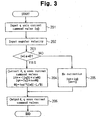
- Fig. 3 is a flowchart of the control performed by the current command value generator 43.
- the angular velocity determination circuit 44 first determines whether the absolute value of the input angular velocity ⁇ is greater than or equal to a predetermined threshold value, that is, an angular velocity ⁇ 0 (S203).
- Iq0) ⁇ sin ⁇ 0 and Iq* Iq0xcos ⁇ 0 (S204).
- the phase advancing angle ⁇ 0 is the delay angle ⁇ (in the second embodiment 19°) corresponding to the angular velocity ⁇ 0.
- the current command value generator 43 (d, q axes current command value calculator 46) serves as a command determination circuit and the angular velocity determination circuit 44 serves as a condition determination circuit.
- a d-axis current and a q-axis current having a value equivalent to the sum of the vector components (in the d axis direction and the q axis direction) of the d-axis current command value Id* and the q-axis current command value Iq* on the d'-q' coordinate axes for control are generated in the original d axis and q axis.
- ⁇ sin ⁇ 0 and Iq* Iq0 ⁇ cos ⁇ 0 when the absolute value of the angular velocity ⁇ of the brushless motor 4 is greater than or equal to the predetermined angular velocity ⁇ 0.
- ⁇ sin( ⁇ - ⁇ 0), and the q-axis current value Iq on the original q axis is expressed by the equation Iq Iq0 ⁇ sin( ⁇ - ⁇ 0).
- the second embodiment has the advantages described below.
- d-axis current expressed by the equation Id
- ⁇ sin( ⁇ - ⁇ 0) is generated on the original d axis
- torque close to the target value is generated, even when the angular velocity ⁇ increases, while suppressing torque reduction caused by the influence of the motor inductance. Further, the generation of positive d-axis current on the original d axis is suppressed, and the reduction of q-axis current when the motor is heated or when the d axis interference term is increased is prevented.
- the calculation load is small compared to when sequentially calculating the phase advancing angle in response to the angular velocity ⁇ .
- the necessary memory capacity is small compared to when storing a map associating the angular velocity ⁇ and the phase advancing angle in the memory. Therefore, an inexpensive microcomputer having low computing power or small memory capacity may be used. This reduces costs.
- a controller for a DC brushless motor according to a third embodiment of the present invention will now be described. Like or same reference numerals are given to those components that are the same as the corresponding components of the second embodiment and will not be described.
- a motor controller 51 shown in Fig. 6 only differs from the motor controller 41 of the second embodiment in a current command value generator 53.
- the current command value generator 53 includes an angular velocity determination circuit 54, for performing conditional determination based on the angular velocity ⁇ , a phase advancing angle calculator 55, for calculating the phase advancing angle ⁇ ', and a d, q axes current command value calculator 56 for calculating the d-axis current command value Id* and the q-axis current command value Iq* based on the calculated phase advancing angle ⁇ '.
- the angular velocity determination circuit 54 first determines whether
- •L/R is less than or equal to a predetermined value (in the third embodiment ⁇ 1) that is set in advance (S303). The phase advancing angle calculator 55 then calculates the phase advancing angle ⁇ ' in accordance with the determination of the angular velocity determination circuit 54 (S304, S305).
- the phase advancing angle calculator 55 calculates the delay angle ⁇ of the phase of the phase current with respect to the phase of the phase voltage command based on the function of the angular velocity ⁇ and the motor inductance L and calculates the phase advancing angle ⁇ ' corresponding to the delay angle ⁇ (S304).
- a predetermined value (angle) ⁇ is used as the phase advancing angle ⁇ ' (S305).
- ⁇ sin ⁇ ' and Iq* Iq0xcos ⁇ (S306).
- the current command value generator 53 then provides the d-axis current command value Id* and the q-axis current command value Iq* to the subtracters 15, 16, respectively (S307).
- the current command value generator 53 (d, q axes current command value calculator 56) serves as the command determination circuit, and the angular velocity determination circuit 54 serves as the condition determination circuit.
- the third embodiment has the advantages described below.
- phase current sensors 6 to 8 are used to detect the phase current value Iu, Iv, Iw.
- the present invention is not limited to such a configuration, and any two-phase currents may be detected from the phase current values Iu, Iv, and Iw with two current sensors, and the remaining phase current may be detected from the detected two-phase currents through a calculation.
- the phase advancing angle calculator 35 determines the phase advancing angle ⁇ corresponding to the angular velocity ⁇ that is input by referring to the map.
- the phase advancing control unit 33 adds the phase advancing angle ⁇ , which is calculated based on the function of the angular velocity ⁇ and the motor inductance L (and armature wiring resistance R), to the rotation angle ⁇ , which is calculated by the rotation angle calculator 12, and provides the sum to the two-phase/three-phase converter 3 as the corrected rotation angle ⁇ '.
- the present invention is not limited to such a configuration, and a predetermined phase advancing angle set in advance may be added to the rotation angle ⁇ calculated by the rotation angle calculator 12.
- a condition determination circuit for performing a conditional determination based on the angular velocity ⁇ may be used like in the angular velocity determination circuits 44 and 54 of the second and the third embodiments.
- the phase advancing calculator may calculate the phase advancing angle based on the above function or may use a predetermined value as the phase advancing angle. Alternatively, calculation of the phase advancing angle may be eliminated.
- the angular velocity determination circuits 44 and 54 respectively include the current command value generators 43 and 53.
- the present invention is not limited to such a configuration, and the angular velocity determination circuit may be omitted so that the d-axis current command value Id* and the q-axis current command value Iq* are determined from a uniform calculation mode irrespective of the angular velocity ⁇ as in the phase advancing control unit 33 of the first embodiment.
- the d-axis current command value Id* and the q-axis current command value Iq* may be determined by using the phase advancing angle calculated based on the above function or by using the predetermined phase advancing angle.
- the predetermined angular velocity ⁇ 0 and the phase advancing angle ⁇ 0 may be set to any value.
- ⁇ sin ⁇ 0 and Iq* Iq0 ⁇ cos ⁇ 0 when
- the predetermined value ⁇ and the predetermined value ⁇ may be set to any value.
- the angular velocity determination circuit 54 determines whether the
- •L/R is less than or equal to a predetermined value ⁇ (in the third embodiment ⁇ l).
- the present invention is not limited to such a configuration, and the angular velocity determination circuit may perform the determination based on whether the absolute value of the angular velocity ⁇ is less than or equal to a predetermined value.
- the phase advancing angle calculator 55 calculates the phase advancing angle ⁇ ' based on the above function when the angular velocity determination circuit 54 is
- An adder (36) adds the phase advancing angle to the rotation angle ( ⁇ ) provided from the rotation angle calculator to generate the corrected rotation angle ( ⁇ '). The adder further provides the corrected rotation angle to a two-phase/three-phase converter (21).
Landscapes
- Engineering & Computer Science (AREA)
- Power Engineering (AREA)
- Control Of Motors That Do Not Use Commutators (AREA)
- Control Of Ac Motors In General (AREA)
Abstract
Description
Claims (10)
- A controller for controlling a three-phase brushless motor, the controller characterized by:a three-phase/two-phase converter for converting values of three-phase current provided to the brushless motor to two-phase current values;a two-phase/three-phase converter for converting two-phase voltage command values in accordance with the difference between the two-phase current values and the two-phase current command values to generate three-phase voltage command values;a rotation angle detector for detecting rotation angle of the brushless motor;an angular velocity calculator for calculating angular velocity of the brushless motor;a phase advancing angle calculator for calculating a phase advancing angle corresponding to a delay angle of the phase of the phase current with respect to the phase of the phase voltage command resulting from influence of inductance of the motor based on a function of the angular velocity and the inductance; anda rotation angle corrector for adding the phase advancing angle to the rotation angle to generate a corrected rotation angle, wherein the two-phase/three-phase converter performs two-phase/three-phase conversion using the corrected rotation angle.
- The controller as claimed in claim 1, wherein the function is an equation expressed by ϕ=tan-1(ω•L/R) or an approximation thereof, where ϕ represents the delay angle, ω represents the angular velocity, L represents the inductance, and R represents the armature winding resistance.
- The controller as claimed in claim 1, wherein:the phase advancing angle calculator is connected to the angular velocity calculator; andthe rotation angle corrector is connected to the two-phase/three-phase converter, the rotation angle detector, and the phase advancing angle calculator.
- The controller as claimed in claim 1, wherein the two-phase current command values are a d-axis current command value and a q-axis current command value, the two-phase current values are a d-axis current value and a q-axis current value, and the two-phase voltage command values are a d-axis voltage command value and a q-axis voltage command value, the controller further comprising:a first subtracter, connected to the three-phase/two-phase converter, for calculating the difference between the d-axis current value and the d-axis current command value;a first PI control unit, connected to the first subtracter and the two-phase/three-phase converter, for generating the d-axis voltage command value;a second subtracter, connected to the three-phase/two-phase converter, for calculating the difference between the q-axis current value and the q-axis current command value; anda second PI control unit, connected to the second subtracter and the two-phase/three-phase converter, for generating the q-axis voltage command value.
- A controller for controlling a three-phase brushless motor, the controller characterized by:a three-phase/two-phase converter for converting values of three phase currents provided to the brushless motor to generate two-phase current values including a d-axis current value and a q-axis current value;a two-phase/three-phase converter for converting a d-axis voltage command value and a q-axis voltage command value to three-phase voltage command values, the d-axis voltage command value being corresponding to the difference between the d-axis current value and a d-axis current command value, and the q-axis voltage command value being corresponding to the difference between the q-axis current value and a q-axis current command value;an angular velocity calculator for calculating angular velocity of the brushless motor;a condition determination circuit for determining whether absolute value of the angular velocity is equal to or greater than a predetermined value; anda command determination circuit for determining the d-axis current command value and the q-axis current command value based on the determination of the condition determination circuit, wherein the command determination circuit:determines the d-axis current command value and the q-axis current command value from the equations ofdetermines zero as the d-axis current command value and Iq0 as the q-axis current command value if the absolute value of the angular velocity is smaller than the predetermined value.
- The controller as claimed in claim 5, further comprising:wherein the rotation angle detector is connected to the three-phase/two-phase converter, the two-phase/three-phase converter, and the angular velocity calculator.a first subtracter, connected to the three-phase/two-phase converter and the command determination circuit, for calculating the difference between the d-axis current value and the d-axis current command value;a first PI control unit, connected to the first subtracter and the two-phase/three-phase converter, for generating the d-axis voltage command value;a second subtracter, connected to the three-phase/two-phase converter and the command determination circuit, for calculating the difference between the q-axis current value and the q-axis current command value; anda second PI control unit, connected to the second subtracter and the two-phase/three-phase converter, for generating the q-axis voltage command value;
- A controller for controlling a three-phase brushless motor, the controller characterized by:where Id* represents the d-axis current command value, Iq* represents the q-axis current command value, Iq0 represents the input q-axis current command value, and Φ' represents the phase advancing angle.a three-phase/two-phase converter for converting values of three-phase currents provided to the brushless motor to generate two-phase current values including a d-axis current value and a q-axis current value;a two-phase/three-phase converter for converting a d-axis voltage command value and a q-axis voltage command value to generate three-phase voltage command values, the d-axis voltage command value being corresponding to the difference between the d-axis current value and a d-axis current command value, and the q-axis voltage command value being corresponding to the difference between the q-axis current value and a q-axis current command value;an angular velocity calculator for calculating angular velocity of the brushless motor;a condition determination circuit for performing a conditional determination based on the angular velocity; anda phase advancing angle calculator for performing either one of a process for calculating a phase advancing angle corresponding to a delay angle of the phase of the phase current with respect to the phase of the phase voltage command resulting from influence of inductance of the motor based on a function of the angular velocity and the motor inductance and a process for using a predetermined angle as the phase advancing angle, in accordance with the determination of the condition determination circuit; anda command determination circuit for determining the d-axis current command value and the q-axis current command value in accordance with the phase advancing angle and an equation of
- The controller as claimed in claim 7, wherein the function is an equation expressed by ϕ=tan-1(ω•L/R) or an approximation thereof, where ϕ represents the delay angle, ω represents the angular velocity, L represents the inductance, and R represents the armature winding resistance.
- The controller as claimed in claim 7, wherein:the condition determination circuit determines whether a value of |ω|•L/R is less than or equal to a predetermined value, where ω represents the angular velocity, L represents the motor inductance, and R represents the armature winding resistance; andthe phase advancing angle calculator calculates the phase advancing angle based on the function when the value of |ω|•L/R is less than or equal to the predetermined value and sets the predetermined angle as the phase advancing angle when the value of |ω|•L/R is greater than the predetermined value.
- The controller as claimed in claim 7, further comprising:wherein the rotation angle detector is connected to the three-phase/two-phase converter, the two-phase/three-phase converter, and the angular velocity calculator.a first subtracter, connected to the three-phase/two-phase converter and the command determination circuit, for calculating the difference between the d-axis current value and the d-axis current command value;a first PI control unit, connected to the first subtracter and the two-phase/three-phase converter, for generating the d-axis voltage command value;a second subtracter, connected to the three-phase/two-phase converter and the command determination circuit, for calculating the difference between the q-axis current value and the q-axis current command value; anda second PI control unit, connected to the second subtracter and the two-phase/three-phase converter, for generating the q-axis voltage command value;
Applications Claiming Priority (2)
| Application Number | Priority Date | Filing Date | Title |
|---|---|---|---|
| JP2004013628A JP4561105B2 (en) | 2004-01-21 | 2004-01-21 | Motor control device |
| JP2004013628 | 2004-01-21 |
Publications (3)
| Publication Number | Publication Date |
|---|---|
| EP1557940A2 true EP1557940A2 (en) | 2005-07-27 |
| EP1557940A3 EP1557940A3 (en) | 2011-03-09 |
| EP1557940B1 EP1557940B1 (en) | 2019-12-18 |
Family
ID=34631915
Family Applications (1)
| Application Number | Title | Priority Date | Filing Date |
|---|---|---|---|
| EP05001151.9A Ceased EP1557940B1 (en) | 2004-01-21 | 2005-01-20 | Motor controller |
Country Status (3)
| Country | Link |
|---|---|
| US (1) | US7078873B2 (en) |
| EP (1) | EP1557940B1 (en) |
| JP (1) | JP4561105B2 (en) |
Cited By (3)
| Publication number | Priority date | Publication date | Assignee | Title |
|---|---|---|---|---|
| EP1881594A1 (en) * | 2006-07-20 | 2008-01-23 | Schneider Toshiba Inverter Europe SAS | Method of adjusting parameters of a synchronous motor and variable speed drive using such a method |
| US7943509B2 (en) | 2007-01-05 | 2011-05-17 | Nxp B.V. | Method of making an interconnect structure |
| WO2013009443A3 (en) * | 2011-07-08 | 2013-11-21 | Allegro Microsystems, Llc | Electronic circuit and method generating electric motor drive signals having phase advances in accordance with a user selected relationship between rotational speed of an electric motor and the phase advances |
Families Citing this family (12)
| Publication number | Priority date | Publication date | Assignee | Title |
|---|---|---|---|---|
| JP4289458B2 (en) * | 2004-09-07 | 2009-07-01 | 三菱電機株式会社 | Electric power steering control device |
| JP5470697B2 (en) * | 2007-06-20 | 2014-04-16 | 株式会社ジェイテクト | Electric power steering device |
| JP5167717B2 (en) * | 2007-08-08 | 2013-03-21 | 日本精工株式会社 | Motor drive control device and electric power steering device using motor drive control device |
| JP2009261121A (en) * | 2008-04-16 | 2009-11-05 | Asmo Co Ltd | Motor control apparatus |
| JP5535165B2 (en) * | 2011-09-26 | 2014-07-02 | 株式会社東芝 | Semiconductor device and motor drive device |
| KR101928435B1 (en) * | 2012-06-19 | 2018-12-12 | 삼성전자주식회사 | Power conversion apparatus and method for controlling the same |
| US10065278B2 (en) | 2013-01-22 | 2018-09-04 | Western Industries Incorporated | Spill resistant warming drawer |
| US8975842B2 (en) * | 2013-06-21 | 2015-03-10 | Hamilton Sundstrand Corporation | Permanent magnet motor control |
| KR102155814B1 (en) * | 2014-06-16 | 2020-09-17 | 엘에스일렉트릭(주) | Apparatus for Delay Angle Compensation of Flying Start Function |
| US9343102B1 (en) * | 2015-03-25 | 2016-05-17 | Western Digital Technologies, Inc. | Data storage device employing a phase offset to generate power from a spindle motor during a power failure |
| US9355676B1 (en) * | 2015-03-25 | 2016-05-31 | Western Digital Technologies, Inc. | Data storage device controlling amplitude and phase of driving voltage to generate power from a spindle motor |
| CN107222145B (en) * | 2017-07-27 | 2019-09-06 | 广东美芝制冷设备有限公司 | Control method, system and the machine readable storage medium of permanent magnet synchronous motor |
Citations (1)
| Publication number | Priority date | Publication date | Assignee | Title |
|---|---|---|---|---|
| JP2001178199A (en) | 1999-12-15 | 2001-06-29 | Toyoda Mach Works Ltd | Motor controller |
Family Cites Families (13)
| Publication number | Priority date | Publication date | Assignee | Title |
|---|---|---|---|---|
| JP3399156B2 (en) * | 1995-05-29 | 2003-04-21 | 株式会社デンソー | Control device for brushless DC motor |
| JP3397007B2 (en) * | 1995-06-30 | 2003-04-14 | 松下電器産業株式会社 | Brushless motor |
| JP3281561B2 (en) * | 1996-12-25 | 2002-05-13 | シャープ株式会社 | Motor speed control device |
| US6081087A (en) * | 1997-10-27 | 2000-06-27 | Matsushita Electric Industrial Co., Ltd. | Motor control apparatus |
| US6462491B1 (en) * | 1999-01-27 | 2002-10-08 | Matsushita Electric Industrial Co., Ltd. | Position sensorless motor control apparatus |
| US6373211B1 (en) * | 1999-09-17 | 2002-04-16 | Delphi Technologies, Inc. | Extended speed range operation of permanent magnet brushless machines using optimal phase angle control in the voltage mode operation |
| JP3502040B2 (en) * | 2000-12-27 | 2004-03-02 | 本田技研工業株式会社 | Brushless DC motor constant detection device, brushless DC motor control device, and brushless DC motor constant detection program |
| US7071649B2 (en) * | 2001-08-17 | 2006-07-04 | Delphi Technologies, Inc. | Active temperature estimation for electric machines |
| JP3775290B2 (en) * | 2001-11-29 | 2006-05-17 | 日産自動車株式会社 | Motor control device |
| JP3644922B2 (en) * | 2001-12-06 | 2005-05-11 | 本田技研工業株式会社 | Electric power steering device |
| JP2002291298A (en) * | 2002-03-25 | 2002-10-04 | Hitachi Ltd | Motor control device and control device for electric vehicle |
| US7436139B2 (en) * | 2003-01-29 | 2008-10-14 | Matra Manufacturing & Services Sas | Phase advance angle optimization for brushless motor control |
| US6911794B2 (en) * | 2003-05-08 | 2005-06-28 | Wavecrest Laboratories, Llc | Precision adaptive motor control in cruise control system having various motor control schemes |
-
2004
- 2004-01-21 JP JP2004013628A patent/JP4561105B2/en not_active Expired - Fee Related
-
2005
- 2005-01-20 EP EP05001151.9A patent/EP1557940B1/en not_active Ceased
- 2005-01-21 US US11/038,195 patent/US7078873B2/en not_active Expired - Lifetime
Patent Citations (1)
| Publication number | Priority date | Publication date | Assignee | Title |
|---|---|---|---|---|
| JP2001178199A (en) | 1999-12-15 | 2001-06-29 | Toyoda Mach Works Ltd | Motor controller |
Cited By (6)
| Publication number | Priority date | Publication date | Assignee | Title |
|---|---|---|---|---|
| EP1881594A1 (en) * | 2006-07-20 | 2008-01-23 | Schneider Toshiba Inverter Europe SAS | Method of adjusting parameters of a synchronous motor and variable speed drive using such a method |
| FR2904163A1 (en) * | 2006-07-20 | 2008-01-25 | Schneider Toshiba Inverter | METHOD FOR ADJUSTING PARAMETERS OF A SYNCHRONOUS MOTOR AND SPEED VARIATOR USING SUCH A METHOD |
| US7646164B2 (en) | 2006-07-20 | 2010-01-12 | Schneider Toshiba Inverter Europe Sas | Method of adjusting parameters of a synchronous motor and variable speed drive using such a method |
| US7943509B2 (en) | 2007-01-05 | 2011-05-17 | Nxp B.V. | Method of making an interconnect structure |
| WO2013009443A3 (en) * | 2011-07-08 | 2013-11-21 | Allegro Microsystems, Llc | Electronic circuit and method generating electric motor drive signals having phase advances in accordance with a user selected relationship between rotational speed of an electric motor and the phase advances |
| US8729841B2 (en) | 2011-07-08 | 2014-05-20 | Allegro Microsystems, Llc | Electronic circuit and method generating electric motor drive signals having phase advances in accordance with a user selected relationship between rotational speed of an electric motor and the phase advances |
Also Published As
| Publication number | Publication date |
|---|---|
| US20050156549A1 (en) | 2005-07-21 |
| US7078873B2 (en) | 2006-07-18 |
| JP2005210814A (en) | 2005-08-04 |
| EP1557940A3 (en) | 2011-03-09 |
| JP4561105B2 (en) | 2010-10-13 |
| EP1557940B1 (en) | 2019-12-18 |
Similar Documents
| Publication | Publication Date | Title |
|---|---|---|
| JP4168730B2 (en) | Control device for three-phase AC motor | |
| US7928675B2 (en) | Feedback control method and apparatus for electric motor | |
| US6674262B2 (en) | Motor control apparatus and motor control method | |
| US7548038B2 (en) | Controller for motor | |
| JP5549384B2 (en) | Electric motor control device and electric motor control system | |
| US9112436B2 (en) | System for controlling controlled variable of rotary machine | |
| AU2009345453B2 (en) | Power conversion device | |
| US10778130B2 (en) | Control apparatus for alternating-current rotary electric machine | |
| JP4881635B2 (en) | Vector controller for permanent magnet motor | |
| EP1557940B1 (en) | Motor controller | |
| JP2000228892A (en) | Control device for synchronous motor | |
| US9548688B2 (en) | Motor control apparatus | |
| WO2008047438A1 (en) | Vector controller of permanent magnet synchronous motor | |
| JP3674741B2 (en) | Control device for permanent magnet synchronous motor | |
| EP1583217A1 (en) | Motor drive-controlling device and electric power-steering device | |
| JP7385538B2 (en) | Power converter, temperature estimation method and program | |
| JP4912516B2 (en) | Power converter | |
| EP1280264B1 (en) | AC current detecting device for inverter apparatus and AC current detecting method therefor | |
| US8129935B2 (en) | Motor control device | |
| JP2000037098A (en) | Power conversion device using speed sensorless vector control | |
| JP2004061217A (en) | Current detection device and method, and motor device | |
| JP2008154308A (en) | Electric power steering control device | |
| JP2002191198A (en) | Method for correcting DC voltage detection value of motor drive device, motor drive control device | |
| JP2001136775A (en) | Load estimation method for permanent magnet rotor type synchronous motor and control device for permanent magnet rotor type synchronous motor | |
| JP2023127886A (en) | motor drive system |
Legal Events
| Date | Code | Title | Description |
|---|---|---|---|
| PUAI | Public reference made under article 153(3) epc to a published international application that has entered the european phase |
Free format text: ORIGINAL CODE: 0009012 |
|
| AK | Designated contracting states |
Kind code of ref document: A2 Designated state(s): AT BE BG CH CY CZ DE DK EE ES FI FR GB GR HU IE IS IT LI LT LU MC NL PL PT RO SE SI SK TR |
|
| AX | Request for extension of the european patent |
Extension state: AL BA HR LV MK YU |
|
| RAP1 | Party data changed (applicant data changed or rights of an application transferred) |
Owner name: TOYODA KOKI KABUSHIKI KAISHA Owner name: FAVESS CO., LTD. Owner name: JTEKT CORPORATION |
|
| RAP1 | Party data changed (applicant data changed or rights of an application transferred) |
Owner name: JTEKT CORPORATION |
|
| PUAL | Search report despatched |
Free format text: ORIGINAL CODE: 0009013 |
|
| AK | Designated contracting states |
Kind code of ref document: A3 Designated state(s): AT BE BG CH CY CZ DE DK EE ES FI FR GB GR HU IE IS IT LI LT LU MC NL PL PT RO SE SI SK TR |
|
| AX | Request for extension of the european patent |
Extension state: AL BA HR LV MK YU |
|
| RIC1 | Information provided on ipc code assigned before grant |
Ipc: H02P 21/00 20060101AFI20050511BHEP Ipc: H02P 6/14 20060101ALI20110202BHEP |
|
| 17P | Request for examination filed |
Effective date: 20110909 |
|
| AKX | Designation fees paid |
Designated state(s): DE FR |
|
| 17Q | First examination report despatched |
Effective date: 20181105 |
|
| GRAP | Despatch of communication of intention to grant a patent |
Free format text: ORIGINAL CODE: EPIDOSNIGR1 |
|
| INTG | Intention to grant announced |
Effective date: 20190704 |
|
| GRAS | Grant fee paid |
Free format text: ORIGINAL CODE: EPIDOSNIGR3 |
|
| GRAA | (expected) grant |
Free format text: ORIGINAL CODE: 0009210 |
|
| AK | Designated contracting states |
Kind code of ref document: B1 Designated state(s): DE FR |
|
| REG | Reference to a national code |
Ref country code: DE Ref legal event code: R096 Ref document number: 602005056489 Country of ref document: DE |
|
| REG | Reference to a national code |
Ref country code: DE Ref legal event code: R097 Ref document number: 602005056489 Country of ref document: DE |
|
| PLBE | No opposition filed within time limit |
Free format text: ORIGINAL CODE: 0009261 |
|
| STAA | Information on the status of an ep patent application or granted ep patent |
Free format text: STATUS: NO OPPOSITION FILED WITHIN TIME LIMIT |
|
| 26N | No opposition filed |
Effective date: 20200921 |
|
| PGFP | Annual fee paid to national office [announced via postgrant information from national office to epo] |
Ref country code: FR Payment date: 20201210 Year of fee payment: 17 |
|
| PGFP | Annual fee paid to national office [announced via postgrant information from national office to epo] |
Ref country code: DE Payment date: 20210105 Year of fee payment: 17 |
|
| REG | Reference to a national code |
Ref country code: DE Ref legal event code: R119 Ref document number: 602005056489 Country of ref document: DE |
|
| PG25 | Lapsed in a contracting state [announced via postgrant information from national office to epo] |
Ref country code: DE Free format text: LAPSE BECAUSE OF NON-PAYMENT OF DUE FEES Effective date: 20220802 |
|
| PG25 | Lapsed in a contracting state [announced via postgrant information from national office to epo] |
Ref country code: FR Free format text: LAPSE BECAUSE OF NON-PAYMENT OF DUE FEES Effective date: 20220131 |