EP1557898B1 - Brennstoffzellenstapel mit einer Filtervorrichtung - Google Patents
Brennstoffzellenstapel mit einer Filtervorrichtung Download PDFInfo
- Publication number
- EP1557898B1 EP1557898B1 EP04028834A EP04028834A EP1557898B1 EP 1557898 B1 EP1557898 B1 EP 1557898B1 EP 04028834 A EP04028834 A EP 04028834A EP 04028834 A EP04028834 A EP 04028834A EP 1557898 B1 EP1557898 B1 EP 1557898B1
- Authority
- EP
- European Patent Office
- Prior art keywords
- fuel cell
- filter
- cell stack
- stack according
- main line
- Prior art date
- Legal status (The legal status is an assumption and is not a legal conclusion. Google has not performed a legal analysis and makes no representation as to the accuracy of the status listed.)
- Expired - Lifetime
Links
- 239000000446 fuel Substances 0.000 title claims abstract description 65
- 238000001914 filtration Methods 0.000 claims abstract description 7
- 238000000034 method Methods 0.000 claims abstract description 5
- 238000011045 prefiltration Methods 0.000 claims description 7
- 238000004140 cleaning Methods 0.000 claims description 4
- 238000009833 condensation Methods 0.000 claims description 2
- 230000005494 condensation Effects 0.000 claims description 2
- XLYOFNOQVPJJNP-UHFFFAOYSA-N water Substances O XLYOFNOQVPJJNP-UHFFFAOYSA-N 0.000 claims description 2
- 238000011144 upstream manufacturing Methods 0.000 claims 1
- 238000006243 chemical reaction Methods 0.000 description 8
- 239000003570 air Substances 0.000 description 7
- 239000007789 gas Substances 0.000 description 4
- 239000002245 particle Substances 0.000 description 4
- QVGXLLKOCUKJST-UHFFFAOYSA-N atomic oxygen Chemical compound [O] QVGXLLKOCUKJST-UHFFFAOYSA-N 0.000 description 3
- 239000001257 hydrogen Substances 0.000 description 3
- 229910052739 hydrogen Inorganic materials 0.000 description 3
- 239000001301 oxygen Substances 0.000 description 3
- 229910052760 oxygen Inorganic materials 0.000 description 3
- UFHFLCQGNIYNRP-UHFFFAOYSA-N Hydrogen Chemical compound [H][H] UFHFLCQGNIYNRP-UHFFFAOYSA-N 0.000 description 2
- 239000012080 ambient air Substances 0.000 description 2
- 239000004020 conductor Substances 0.000 description 2
- 239000003792 electrolyte Substances 0.000 description 2
- 239000003344 environmental pollutant Substances 0.000 description 2
- 239000012065 filter cake Substances 0.000 description 2
- 238000012423 maintenance Methods 0.000 description 2
- 239000000463 material Substances 0.000 description 2
- 231100000719 pollutant Toxicity 0.000 description 2
- 239000005518 polymer electrolyte Substances 0.000 description 2
- 229920005597 polymer membrane Polymers 0.000 description 2
- 230000006978 adaptation Effects 0.000 description 1
- 239000003054 catalyst Substances 0.000 description 1
- 238000010349 cathodic reaction Methods 0.000 description 1
- 239000007795 chemical reaction product Substances 0.000 description 1
- 239000011362 coarse particle Substances 0.000 description 1
- 238000010276 construction Methods 0.000 description 1
- 238000011109 contamination Methods 0.000 description 1
- 239000002826 coolant Substances 0.000 description 1
- 230000003247 decreasing effect Effects 0.000 description 1
- 238000009792 diffusion process Methods 0.000 description 1
- 238000007599 discharging Methods 0.000 description 1
- 238000003411 electrode reaction Methods 0.000 description 1
- 230000002349 favourable effect Effects 0.000 description 1
- 238000010438 heat treatment Methods 0.000 description 1
- 150000002431 hydrogen Chemical class 0.000 description 1
- 238000009434 installation Methods 0.000 description 1
- 230000010354 integration Effects 0.000 description 1
- 239000000376 reactant Substances 0.000 description 1
- 230000036647 reaction Effects 0.000 description 1
- 238000010079 rubber tapping Methods 0.000 description 1
- 230000035945 sensitivity Effects 0.000 description 1
- 239000000126 substance Substances 0.000 description 1
- 239000003053 toxin Substances 0.000 description 1
- 231100000765 toxin Toxicity 0.000 description 1
- 108700012359 toxins Proteins 0.000 description 1
- 230000007704 transition Effects 0.000 description 1
Images

Classifications
-
- H—ELECTRICITY
- H01—ELECTRIC ELEMENTS
- H01M—PROCESSES OR MEANS, e.g. BATTERIES, FOR THE DIRECT CONVERSION OF CHEMICAL ENERGY INTO ELECTRICAL ENERGY
- H01M8/00—Fuel cells; Manufacture thereof
- H01M8/06—Combination of fuel cells with means for production of reactants or for treatment of residues
- H01M8/0662—Treatment of gaseous reactants or gaseous residues, e.g. cleaning
-
- H—ELECTRICITY
- H01—ELECTRIC ELEMENTS
- H01M—PROCESSES OR MEANS, e.g. BATTERIES, FOR THE DIRECT CONVERSION OF CHEMICAL ENERGY INTO ELECTRICAL ENERGY
- H01M8/00—Fuel cells; Manufacture thereof
- H01M8/24—Grouping of fuel cells, e.g. stacking of fuel cells
-
- Y—GENERAL TAGGING OF NEW TECHNOLOGICAL DEVELOPMENTS; GENERAL TAGGING OF CROSS-SECTIONAL TECHNOLOGIES SPANNING OVER SEVERAL SECTIONS OF THE IPC; TECHNICAL SUBJECTS COVERED BY FORMER USPC CROSS-REFERENCE ART COLLECTIONS [XRACs] AND DIGESTS
- Y02—TECHNOLOGIES OR APPLICATIONS FOR MITIGATION OR ADAPTATION AGAINST CLIMATE CHANGE
- Y02E—REDUCTION OF GREENHOUSE GAS [GHG] EMISSIONS, RELATED TO ENERGY GENERATION, TRANSMISSION OR DISTRIBUTION
- Y02E60/00—Enabling technologies; Technologies with a potential or indirect contribution to GHG emissions mitigation
- Y02E60/30—Hydrogen technology
- Y02E60/50—Fuel cells
Definitions
- the invention relates to a fuel cell stack with a filter device according to the preamble of claim 1.
- part of the reaction enthalpy converted thereby can be obtained directly as an electric current.
- a polymer electrolyte fuel cell consists essentially of a functioning as an electrolyte polymer membrane, which separates the reactants hydrogen and oxygen from each other and has a (H + ) proton conductivity, and two occupied with catalyst material electrodes, among other things, for tapping the generated by the fuel cell electric current are required.
- Electrodes and polymer membrane are usually compacted into a membrane-electrode assembly (MEA).
- MEA membrane-electrode assembly
- bipolar plates are used, which consist of electrically conductive material and are provided with gas distribution structures that allow the arrival and removal of Mattersedukte and reaction products.
- the distribution structures in the individual fuel cells usually have a meandering geometry in order to supply the MEA optimally with the operating media and to allow a favorable discharge.
- This complex which is referred to below as a stack construction, which is also referred to as a fuel cell stack, consists of one or more planar individual fuel cells stacked on top of each other and arranged in an electrical series circuit.
- main lines which are passed axially through the stack structure and which supply the individual fuel cells by laterally branching via branch lines channel structures with the operating media.
- Suitable filters are for example in the US 2003/0096148 and the WO 02/122234 described.
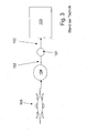
- the filtering operation takes place through a filter body 101, which is arranged in the supply line 102 between Brenstoffzellenstäpel 103 and air compressor 104 or fan (at low pressure cells), the air from the environment, in Fig. 3 designated by the reference numeral 105, is sucked.
- a main line (not shown) with the abovementioned branch lines and channel structures is provided in the interior of the fuel cell stack 103.
- the task results to run the fuel cell stack with filter device as small as possible.
- the pressure losses should be kept as small as possible with a view to higher required compressor outputs, decreasing efficiencies and longer maintenance intervals.
- a fuel cell stack is provided with a filter device for filtering an operating medium, which is supplied to the fuel cell stack, with a filter, in which the filter is integrated into the fuel cell stack.
- the filter is introduced into an axial main line of the fuel cell stack, wherein between the outer surface of the filter and the wall of the main line, a gap is provided, so that over the largest possible area filtering can take place.
- the integration of the filter in the fuel cell stack eliminates the additional space required for an external filter, as provided in the prior art, and the cost of an external filter housing. Further, the number of terminals can be reduced by two, since a connection of the supply line to the filter housing for supplying and discharging the operating medium to be filtered is omitted, whereby the pressure drop can be reduced.
- the positioning of the filter is preferably carried out by means arranged in the gap support and positioning elements, which ensure a central arrangement.
- the filter preferably has a hollow cylindrical profile, but in principle also other embodiments are possible.
- a cleaning device is preferably provided, which is formed in particular by an electrical heatability of the filter.
- the filter can be arranged in a replaceable module, so that it can be easily replaced without damage during installation.
- the module can be designed like a cartridge.
- the filter is at least partially formed hygroscopic and / or has capillaries that absorb condensation occurring and / or allow humidification of the operating medium.
- a pre-filter In front of the fuel cell stack may be arranged a pre-filter, which filters out in particular larger particles, so that the filter inside the fuel cell stack can fulfill its function as long as possible.
- the filter may also project beyond the fuel cell stack and be accommodated in part in a housing, in particular a hose, connected to the feed line.
- the invention also relates to a method for operating a fuel cell stack with at least two fuel cells and a feed line via a main line and at least two operating resources, characterized in that at least one operating medium is cleaned by means of a filter inside the fuel cell stack.
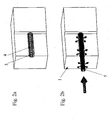
- a fuel cell stack 1 as in Fig. 2a and 2b is indicated, consists of a plurality of individual fuel cells, which in turn are composed of two bipolar plates and a MEA arranged therebetween (not shown).
- the individual fuel cells are supplied via one or more, common main lines 3 and thereof in the form of stubs outgoing branches 4 with operating media, in particular with coolant, and hydrogen (H 2 ) and air (in particular O 2 ), which for the above described reaction are required.
- H 2 hydrogen
- O 2 oxygen
- a filter 5 for filtering the serving as the operating medium ambient air is formed as a hollow cylinder, wherein the air to be filtered flows through the filter 5 in the longitudinal direction and exits through the side walls over substantially the entire length and the entire circumference of the hollow cylinder, as in the FIGS. 1 and 2 B indicated.
- the hollow cylindrical filter 5 is arranged approximately concentrically in the likewise substantially cylindrical main line 3, wherein apart from support and positioning elements (not shown) an annular gap between the outer circumferential surface of the filter 5 and the inner surface of the main line 3 is provided, so that as possible large outflow area is guaranteed.
- the filter 5 has approximately or approximately the same length as the main line 3, wherein seals at the front and rear ends of the filter 5 are provided, which prevent an escape of unfiltered air to the stubs.
- the filter is electrically heated and consists of a temperature-resistant filter material. If the pressure drop due to a growing filter cake exceeds a predetermined value or if a renewal is required due to saturation of the filter with pollutants, reversing the gas flow in conjunction with heating the filter can "burn off" the pollutants and / or filtered-out particles done and thereby the filter to be cleaned.
- the arrangement of the filter in the fuel cell stack corresponds to that of the first embodiment.
- a pre-filter is arranged in front of a filter device according to one of the embodiments described above, wherein the arrangement and the structure of the pre-filter corresponds to one of the prior art.
- a pre-filter is particularly useful in heavily and / or contaminated with large particles operating media, so preferably a pre-cleaning is done in a coarse pre-filter and the fine filter inside the fuel cell stack is not added by coarse particles.
- the pre-filter may be self-cleaning.
- the hollow cylindrical filter extends such extended that it extends beyond the housing of the fuel cell, wherein it is arranged outside concentrically in a hose connected to the supply line, so that also according to this Embodiment only one of the flow cross-section smaller and thus the pressure drop increasing transition from supply line to the filter or fuel cell housing is provided.
- the filter as well as the hose is preferably elastic, so that with an enlarged filter surface outside of the fuel cell housing an optimal and flexible adaptation to the existing space is possible.
Landscapes
- Life Sciences & Earth Sciences (AREA)
- Engineering & Computer Science (AREA)
- Manufacturing & Machinery (AREA)
- Sustainable Development (AREA)
- Sustainable Energy (AREA)
- Chemical & Material Sciences (AREA)
- Chemical Kinetics & Catalysis (AREA)
- Electrochemistry (AREA)
- General Chemical & Material Sciences (AREA)
- Fuel Cell (AREA)
Description
- Die Erfindung betrifft einen Brennstoffzellenstapel mit einer Filtervorrichtung gemäß dem Oberbegriff des Anspruches 1.
- Die Umwandlung von chemischer in elektrische Energie mittels Polymerelektrolyt-Brennstoffzellen stellt eine besonders effiziente und umweltfreundliche Methode zur Gewinnung von elektrischem Strom aus den Betriebsmedien Wasserstoff und Sauerstoff dar. Dabei finden zwei räumlich getrennte Elektrodenreaktionen statt, bei denen Elektronen freigesetzt bzw. gebunden werden: H2 ⇒ 2H+ + 2e- (Anodische Reaktion)
2H+ + 2e- + ½ O2 ⇒ H2O (Kathodische Reaktion) - Durch elektrische Verbindung der räumlich getrennten Reaktionszonen kann ein Teil der dabei umgesetzten Reaktionsenthalpie direkt als elektrischer Strom gewonnen werden.
- Eine Polymerelektrolyt-Brennstoffzelle besteht im wesentlichen aus einer als Elektrolyt fungierenden Polymermembran, welche die Reaktanden Wasserstoff und Sauerstoff voneinander trennt und eine (H+-)Protonenleitfähigkeit aufweist, sowie aus zwei mit Katalysatormaterial belegten Elektroden, die unter anderem zum Abgriff des von der Brennstoffzelle erzeugten elektrischen Stroms erforderlich sind.
- Elektroden und Polymermembran werden gewöhnlich zu einer Membran-Elektroden-Anordnung (MEA) kompaktiert. Zur technischen Realisierung zweier durch den Elektrolyt voneinander getrennten, elektrisch über einen Außenleiter verbundenen Gasräume werden Bipolarplatten verwendet, die aus elektrisch leitfähigem Material bestehen und mit Gasverteilerstrukturen versehen sind, die den An- und Abtransport der Reaktionsedukte und Reaktionsprodukte ermöglichen. Die Verteilerstrukturen in den einzelnen Brennstoffzellen weisen meist eine mäanderförmige Geometrie auf, um die MEA optimal mit den Betriebsmedien zu versorgen und eine günstige Abfuhr zu ermöglichen.
- Somit besteht eine technische Brennstoff-Einzelzelle aus einer MEA, sowie zwei Bipolarplatten, die über Versorgungsanschlüsse mit den Betriebsmedien beaufschlagt und über die das Reaktionswasser abgeführt werden und die den beim Prozess auftretenden elektrischen Strom transportieren können.
- Da die maximal erzielbare Zellenspannung einer Einzel-Brennstoffzelle physikalisch begrenzt ist und im Anwendungsfall regelmäßig unter 1 V, typischerweise im Bereich von 0,5 bis 0,7 V liegt, werden zur Herstellung höherer Spannungen und Leistungen mehrere Einzel-Brennstoffzellen in Form einer elektrischen Serienschaltung zusammengeschaltet. Dieser im Folgenden als Stapelaufbau bezeichnete Komplex, welcher auch als Brennstoffzellenstack bezeichnet wird, besteht aus einer oder mehreren aufeinandergestapelten und in einer elektrischen Serienschaltung angeordneten, planaren Einzel-Brennstoffzellen.
- Zur Versorgung der einzelnen Brennstoffzellen im Brennstoffzellenstapel mit den jeweiligen Betriebsmedien werden große Hauptleitungen, sogenannte Ports, verwendet, welche axial durch den Stapelaufbau hindurchgeführt werden und welche die einzelnen Brennstoffzellen durch seitlich über Stichleitungen abzweigende Kanalstrukturen mit den Betriebsmedien versorgen.
- Auf Grund der großen Menge an Reaktionsluft, die der Brennstoffzelle zur Versorgung der Brennstoffzellenreaktion mit Sauerstoff zugeführt werden müssen, und in Hinblick auf die relative Empfindlichkeit der katalytisch aktiven Bereiche und der damit verbundenen Gasdiffusionszonen gegenüber einer Kontamination durch Giftstoffe und Blockade durch Partikel ist die Filterung der zugeführten Umgebungsluft unbedingt erforderlich.Dafür geeignete Filter sind z.B. in der
US 2003/0096148 und derWO 02122234 - Gemäß dem in
Fig. 3 schematisch dargestellten Stand der Technik findet der Filtervorgang durch einen Filterkörper 101 statt, der in der Zuführungsleitung 102 zwischen Brenstoffzellenstäpel 103 und Luftkompressor 104 oder Lüfter (bei Niederdruckzellen) angeordnet ist, wobei die Luft von aus der Umgebung, inFig. 3 mit dem Bezugszeichen 105 bezeichnet, angesaugt wird. Im Anschluss an die Zuführungsleitung 102 ist im Inneren des Brennstoffzellenstapels 103 eine Hauptleitung (nicht dargestellt) mit den oben genannten Stichleitungen und Kanalstrukturen vorgesehen. - Für den Einsatz bei Anwendungen, die eine sehr kompakte Bauweise erfordern, wie beispielsweise im Kraftfahrzeugsektor, ergibt sich die Aufgabe, den Brennstoffzellenstapel mit Filtervorrichtung möglichst klein auszuführen. Dabei sollen jedoch die Druckverluste mit Blick auf höhere erforderliche Kompressorleistungen, sinkende Wirkungsgrade und längere Wartungsintervalle möglichst klein gehalten werden.
- Es ist Aufgabe der Erfindung, einen verbesserten Brennstoffzellenstapel mit Filtervorrichtung zur Verfügung zu stellen, der insbesondere keinen oder nur minimal zusätzlichen Bauraum erfordert, eine gleichwertige Filterleistung bei einem minimalen Druckverlust aufweist und möglichst kostengünstig herzustellen ist.
- Diese Aufgabe wird gelöst durch einen Brennstoffzellenstapel mit einer Filtervorrichtung mit den Merkmalen des Anspruches 1. Vorteilhafte Ausgestaltungen sind Gegenstand der Unteransprüche.
- Erfindungsgemäß, ist ein Brennstoffzellenstapel mit einer Filtervorrichtung zum Filtern eines Betriebsmediums, das dem Brennstoffzellenstapel zugeführt wird, mit einem Filter vorgesehen, bei welchem der Filter in den Brennstoffzellenstapel integriert ist. Der Filter ist in eine axiale Hauptleitung des Brennstoffzellenstapels eingeführt, wobei zwischen der Außenfläche des Filters und der Wandung der Hauptleitung ein Spalt vorgesehen ist, so dass über eine möglichst große Fläche eine Filterung erfolgen kann. Durch die Integration des Filters in den Brennstoffzellenstapel entfällt der zusätzliche Bauraumbedarf für einen externen Filter, wie gemäß dem Stand der Technik vorgesehen, sowie die Kosten für ein externes Filtergehäuse. Ferner lässt sich die Zahl der Anschlüsse um zwei verringern, da ein Anschluss der Zuleitung an das Filtergehäuse zur Zuleitung und Ableitung des zu filternden Betriebsmediums entfällt, wodurch der Druckabfall verringert werden kann.
- Die Positionierung des filters erfolgt bevorzugt mittels im Spalt angeordneter Stütz- und Positionierungselemente, welche eine mittige Anordnung gewährleisten.
- Auf Grund der großen Filterfläche ergibt sich ein sehr geringer Druckverlust, der in Verbindung mit dem Aufwachsen des Filterkuchens verlängerte Wartungsintervalle ermöglicht.
- Der Filter weist bevorzugt ein hohlzylindrisches Profil auf, jedoch sind prinzipiell auch andere Ausgestaltungen möglich.
- Zur Erhöhung der Lebensdauer eines Filters ist bevorzugt eine Reinigungseinrichtung vorgesehen, welche insbesondere durch eine elektrische Beheizbarkeit des Filters gebildet ist.
- Der Filter kann in einem austauschbaren Modul angeordnet sein, so dass er einfach und ohne Beschädigungen beim Einbau ausgetauscht werden kann. Das Modul kann patronenartig ausgebildet sein.
- Bevorzugt ist der Filter zumindest bereichsweise hygroskopisch ausgebildet und/oder weist Kapillaren auf, die auftretendes Kondenswasser aufnehmen und/oder eine Befeuchtung des Betriebsmediums ermöglichen.
- Vor dem Brennstoffzellenstapel kann ein Vorfilter angeordnet sein, welcher insbesondere größere Partikel ausfiltert, so dass der Filter im Inneren des Brennstoffzellenstapels möglichst lange seine Funktion erfüllen kann.
- Der Filter kann zur Vergrößerung der Filterfläche auch über den Brennstoffzellenstapel hinausragen und in teilweise in einem mit der Zuleitung verbundenen Gehäuse, insbesondere einem Schlauch, aufgenommen sein.
- Gegenstand der Erfindung ist auch ein Verfahren zum Betreiben eines Brennstoffzellenstapels mit mindestens zwei Brennstoffzellen sowie einer über eine Hauptleitung und mindestens zwei Abzweigungen erfolgende Betriebsmittel zufuhr, dadurch gekennzeichnet, dass mindestens ein Betriebsmedium mittels eines Filters im Inneren des Brennstoffzellenstapels gereinigt wird.
- Im Folgenden wird die Erfindung anhand von Ausführungsbeispielen, teilweise unter Bezugnahme auf die Zeichnung, im Einzelnen erläutert. In der Zeichnung zeigen:
- Fig. 1
- eine schematische Darstellung eines Filters, wie er in einem Brennstoffzellenstapel gemäß dem ersten Ausführungsbeispiel verwendet wird,
- Fig. 2a
- eine schematische Darstellung des teilweise aufgeschnittenen Brennstoffzellenstapels ohne Darstellung des Filters,
- Fig. 2b
- eine
Fig. 2a entsprechende Darstellung mit halb herausgezogenem Filter, und - Fig. 3
- eine schematische Darstellung einer herkömmlichen Filtervorrichtung gemäß dem Stand der Technik.
- Ein Brennstoffzellenstapel 1, wie er in
Fig. 2a und 2b angedeutet ist, besteht aus einer Mehrzahl von Einzel-Brennstoffzellen, welche ihrerseits aus zwei Bipolarplatten und einer dazwischen angeordneten MEA aufgebaut sind (nicht dargestellt). Die Einzel-Brennstoffzellen werden über je eine oder je mehrere, gemeinsame Hauptleitungen 3 und hiervon in Form von Stichleitungen abgehenden Abzweigungen 4 mit Betriebsmedien, insbesondere mit Kühlmittel, sowie Wasserstoff (H2) und Luft (insbesondere O2) versorgt, welche für die oben beschriebene Reaktion erforderlich sind. Im Folgenden wird nur auf die Luftversorgungs-Hauptleitung 3 eingegangen. Die Strömungsrichtung ist durch Pfeile angedeutet. - Ein Filter 5 zur Filterung der als Betriebsmedium dienenden Umgebungsluft ist hohlzylindrisch ausgebildet, wobei die zu filternde Luft den Filter 5 in Längsrichtung durchströmt und durch die Seitenwände über im Wesentlichen die gesamte Länge und den gesamten Umfang des Hohlzylinders austritt, wie in den
Figuren 1 und2b angedeutet. Der hohlzylindrische Filter 5 ist etwa konzentrisch in der ebenfalls im Wesentlichen zylinderförmig ausgebildeten Hauptleitung 3 angeordnet, wobei abgesehen von Stütz- und Positionierungselementen (nicht dargestellt) ein Ringspalt zwischen der Außenmantelfläche des Filters 5 und der Innenfläche der Hauptleitung 3 vorgesehen ist, so dass eine möglichst große Ausströmfläche gewährleistet ist. Der Filter 5 weist etwa oder annähernd die gleiche Länge wie die Hauptleitung 3 auf, wobei Abdichtungen am vorderen und hinteren Ende des Filters 5 vorgesehen sind, die einen Austritt von ungefilterter Luft zu den Stichleitungen verhindern. - Gemäß einem zweiten, nicht in der Zeichnung dargestellten Ausführungsbeispiel ist der Filter elektrisch beheizbar und besteht aus einem temperaturbeständigen Filtermaterial. Steigt der Druckabfall auf Grund eines wachsenden Filterkuchens über einen vorgegebenen Wert oder ist auf Grund einer Sättigung des Filters mit Schadstoffen eine Erneuerung erforderlich, so kann durch Umkehrung des Gasflusses in Verbindung mit der Beheizung des Filters ein "Abbrennen" der Schadstoffe und/oder ausgefilterten Partikel erfolgen und dadurch der Filter gereinigt werden. Die Anordnung des Filters im Brennstoffzellenstapel entspricht der des ersten Ausführungsbeispiels.
- Gemäß einem weiteren Ausführungsbeispiel, das nicht in der Zeichnung dargestellt ist, ist vor einer Filtervorrichtung gemäß einem der zuvor beschriebenen Ausführungsbeispiele ein Vorfilter angeordnet, wobei die Anordnung und der Aufbau des Vorfilters einem solchen gemäß dem Stand der Technik entspricht. Ein Vorfilter ist insbesondere bei stark und/oder mit großen Partikeln verschmutzten Betriebsmedien sinnvoll, so dass bevorzugt eine Vorreinigung in einem groben Vorfilter erfolgt und der feine Filter im Inneren des Brennstoffzellenstapels nicht durch grobe Partikel zugesetzt wird. Natürlich kann auch der Vorfilter selbstreinigend ausgebildet sein.
- Zur weiteren Vergrößerung der Filterfläche ist gemäß einem weiteren nicht in der Zeichnung dargestellten Ausführungsbeispiel der hohlzylindrische Filter derart verlängert ausgebildet, dass er über das Gehäuse der Brennstoffzelle hinausragt, wobei er außerhalb in einem an der Zuleitung angeschlossenen Schlauch konzentrisch angeordnet ist, so dass auch gemäß diesem Ausführungsbeispiel lediglich ein den Strömungsquerschnitt verkleinernder und damit den Druckabfall vergrößernder Übergang von Zuleitung zum Filter bzw. Brennstoffzellengehäuse vorgesehen ist. Hierbei ist der Filter wie auch der Schlauch bevorzugt elastisch ausgebildet, so dass bei vergrößerter Filterfläche außerhalb des Brennstoffzellen-Gehäuses eine optimale und flexible Anpassung an den vorhandenen Bauraum möglich ist.
Claims (10)
- Brennstoffzellenstapel (1) bestehend aus einer Mehrzahl von Brennstoffzellen mit einer Filtervorrichtung zum Filtern eines Betriebsmediums, das dem Brennstoffzellenstapel (1) zugeführt wird, mit einem Filter (5), wobei der Filter (5) In den Brennstoffzellenstapel (1) integriert ist, so dass der Filter (5) In eine axiale Hauptleitung (3) des Brennstoffzellenstapels (1) eingeführt ist, dadurch gekennzeichnet, dass zwischen der Außenfläche des Filters (5) und der Wandung der Hauptleitung (3) ein Spalt vorgesehen ist.
- Brennstoffzellenstapel nach Anspruch 1, dadurch gekennzeichnet, dass im Spalt Stütz- und Positionierungselemente angeordnet sind.
- Brennstoffzellenstapel nach einem der vorhergehenden Ansprüche, dadurch gekennzeichnet, dass der Filter (5) hohlzylindrisch ausgebildet ist.
- Brennstoffzellenstapel nach einem der vorhergehenden Ansprüche, dadurch gekennzeichnet, dass eine Reinigungseinrichtung für den Filter (5) vorgesehen ist.
- Brennstoffzellenstapel nach einem der vorhergehenden Ansprüche, dadurch gekennzeichnet, dass der Filter (5) elektrisch beheizbar ist.
- Brennstoffzellenstapel nach einem der vorhergehenden Ansprüche, dadurch gekennzeichnet, dass der Filter (5) in einem austauschbaren Modul angeordnet ist.
- Brennstoffzellenstapel nach einem der vorhergehenden Ansprüche, dadurch gekennzeichnet, dass der Filter (5) zumindest bereichsweise hygroskopisch ausgebildet ist und/oder Kapillaren aufweist, die auftretendes Kondenswasser aufnehmen und/oder eine Befeuchtung des Betriebsmediums ermöglichen.
- Brennstoffzellenstapel nach einem der vorhergehenden Ansprüche, dadurch gekennzeichnet, dass vor dem Brennstoffzellenstapel (1) ein Vorfilter angeordnet ist.
- Brennstoffzellenstapel nach einem der vorhergehenden Ansprüche, dadurch gekennzeichnet, dass der Filter über den Brennstoffzellenstapel (1) hinausragt und in einem mit der Zuleitung verbundenen Gehäuse aufgenommen ist.
- Verfahren zum Betreiben eines Brennstoffzellenstapels (1) gemäss Anspruch 1, mit mindestens zwei Brennstoffzellen sowie einer über eine Hauptleitung (3) und mindestens zwei Abzweigungen (4) erfolgende Betriebsmittelzufuhr, dadurch gekennzeichnet, dass mindestens ein Betriebsmedium mittels eines Filters (5) im Inneren des Brennstoffzellenstapels (1) gereinigt wird.
Applications Claiming Priority (2)
| Application Number | Priority Date | Filing Date | Title |
|---|---|---|---|
| DE102004003273 | 2004-01-21 | ||
| DE102004003273A DE102004003273A1 (de) | 2004-01-21 | 2004-01-21 | Brennstoffzellenstapel mit einer Filtervorrichtung |
Publications (3)
| Publication Number | Publication Date |
|---|---|
| EP1557898A2 EP1557898A2 (de) | 2005-07-27 |
| EP1557898A3 EP1557898A3 (de) | 2007-11-07 |
| EP1557898B1 true EP1557898B1 (de) | 2011-02-23 |
Family
ID=34625752
Family Applications (1)
| Application Number | Title | Priority Date | Filing Date |
|---|---|---|---|
| EP04028834A Expired - Lifetime EP1557898B1 (de) | 2004-01-21 | 2004-12-06 | Brennstoffzellenstapel mit einer Filtervorrichtung |
Country Status (3)
| Country | Link |
|---|---|
| EP (1) | EP1557898B1 (de) |
| AT (1) | ATE499720T1 (de) |
| DE (2) | DE102004003273A1 (de) |
Families Citing this family (1)
| Publication number | Priority date | Publication date | Assignee | Title |
|---|---|---|---|---|
| DE102014205029A1 (de) | 2014-03-18 | 2015-09-24 | Volkswagen Ag | Konditionierungseinheit zur Konditionierung eines Betriebsmediums sowie Brennstoffzellenanordnung mit einer solchen |
Family Cites Families (9)
| Publication number | Priority date | Publication date | Assignee | Title |
|---|---|---|---|---|
| US3991724A (en) * | 1974-03-01 | 1976-11-16 | Universal Oil Products Company | Apparatus for moisture addition to engine air-fuel input |
| US5175062A (en) * | 1991-01-30 | 1992-12-29 | Energy Research Corporation | Reforming unit for fuel cell stack |
| US5632792A (en) * | 1995-08-16 | 1997-05-27 | Purolator Products Company | Air induction filter hose assembly |
| DE19912318A1 (de) * | 1999-03-19 | 2000-09-28 | Dbb Fuel Cell Engines Gmbh | Plattenreaktor |
| US6432177B1 (en) * | 2000-09-12 | 2002-08-13 | Donaldson Company, Inc. | Air filter assembly for low temperature catalytic processes |
| US6780534B2 (en) * | 2001-04-11 | 2004-08-24 | Donaldson Company, Inc. | Filter assembly for intake air of fuel cell |
| US6720102B2 (en) * | 2001-11-21 | 2004-04-13 | Thomas C. Edwards | Rotating fuel cell |
| DE10230283A1 (de) * | 2002-07-05 | 2004-01-29 | Daimlerchrysler Ag | Verfahren und Anordnung zum Reinigen der einer Brennstoffzelle für den Betrieb zuzuführenden Gase von Bestandteilen, die für den Brennstoffzellenbetrieb ungünstig sind |
| US20040023096A1 (en) * | 2002-07-31 | 2004-02-05 | Pratt Steven Duane | Fuel cell system having a filter element for purifying ambient environmental air |
-
2004
- 2004-01-21 DE DE102004003273A patent/DE102004003273A1/de not_active Withdrawn
- 2004-12-06 DE DE502004012220T patent/DE502004012220D1/de not_active Expired - Lifetime
- 2004-12-06 AT AT04028834T patent/ATE499720T1/de active
- 2004-12-06 EP EP04028834A patent/EP1557898B1/de not_active Expired - Lifetime
Also Published As
| Publication number | Publication date |
|---|---|
| EP1557898A3 (de) | 2007-11-07 |
| EP1557898A2 (de) | 2005-07-27 |
| DE502004012220D1 (de) | 2011-04-07 |
| DE102004003273A1 (de) | 2005-08-18 |
| ATE499720T1 (de) | 2011-03-15 |
Similar Documents
| Publication | Publication Date | Title |
|---|---|---|
| DE19635008C2 (de) | Brennstoffzellensystem | |
| WO2000054358A1 (de) | Herstellung von tubulären brennstoffzellen, brennstoffzellenmodulen, grundelementen und ionentauschermembranen | |
| DE102004017848B4 (de) | Verfahren zum Betrieb eines Brennstoffzellensystems sowie ein Brennstoffzellensystem | |
| DE102008013439A1 (de) | Gabelung von Strömungskanälen in Strömungsfeldern von Bipolarplatten | |
| EP1815549B1 (de) | Brennstoffzellensystem mit fl]ssigkeitsabscheider | |
| DE112008001716T5 (de) | Brennstoffzelle | |
| DE102008015350A1 (de) | Modular aufgebauter Brennstoffzellenstapel | |
| EP2280440B1 (de) | Brennstoffzellenvorrichtung mit mehreren Kaskadenstufen | |
| DE102004013689A1 (de) | Filtervorrichtung, insbesondere für einen Brennstoffzellenstapel | |
| DE112005003296B4 (de) | Dekontaminationsprozedur für einen Brennstoffzellenstromerzeuger | |
| WO2010083788A1 (de) | Wiederholeinheit für einen brennstoffzellenstapel | |
| DE102008018275A1 (de) | Konstanter Kanalquerschnitt in einem PEMFC-Auslass | |
| EP1557898A2 (de) | Brennstoffzellenstapel mit einer Filtervorrichtung | |
| WO2002019453A1 (de) | Bipolare platte für eine brennstoffzelle | |
| EP2406847B1 (de) | Brennstoffzellenanordnung und verfahren zum betreiben einer brennstoffzellenanordnung | |
| DE112006000324B4 (de) | Brennstoffzellen-Baugruppe, Brennstoffzellenmodul und Brennstoffzelleneinrichtung | |
| DE102015222552A1 (de) | Brennstoffzellenstapel Bipolarplatten aufweisend sowie Brennstoffzellensystem | |
| EP1522115A1 (de) | Brennstoffzellenstapel mit gegenstromkühlung und einer vielzahl von kühlmittelsammelkanälen parallel zur stapelachse | |
| DE602004010006T2 (de) | Brennstoffzelle mit hoher aktiver Oberfläche | |
| DE102005026244B4 (de) | Brennstoffzellenstapel und Schaltanordnung für einen Brennstoffzellenstapel | |
| DE102015220950A1 (de) | Kathodenversorgung für eine Mehrfach-Brennstoffzelle sowie Verfahren zum Versorgen von Teilbrennstoffzellen mit einem Kathoden-Betriebsmedium | |
| DE102017100738B4 (de) | Brennstoffzellenstapel mit erhöhter Beständigkeit gegenüber Spannungsumkehr sowie Brennstoffzellensystem und Fahrzeug mit einem solchen | |
| DE102019128426A1 (de) | Bipolarplatte, Brennstoffzelle, Brennstoffzellenstapel, Brennstoffzellenvorrichtung sowie Kraftfahrzeug mit einer Brennstoffzellenvorrichtung | |
| EP1947712B1 (de) | Vorrichtung zum Zuführen eines Gasstromes in eine Zelle eines Akkumulators | |
| DE10110819A1 (de) | Bipolare Platte |
Legal Events
| Date | Code | Title | Description |
|---|---|---|---|
| PUAI | Public reference made under article 153(3) epc to a published international application that has entered the european phase |
Free format text: ORIGINAL CODE: 0009012 |
|
| AK | Designated contracting states |
Kind code of ref document: A2 Designated state(s): AT BE BG CH CY CZ DE DK EE ES FI FR GB GR HU IE IS IT LI LT LU MC NL PL PT RO SE SI SK TR |
|
| AX | Request for extension of the european patent |
Extension state: AL BA HR LV MK YU |
|
| PUAL | Search report despatched |
Free format text: ORIGINAL CODE: 0009013 |
|
| AK | Designated contracting states |
Kind code of ref document: A3 Designated state(s): AT BE BG CH CY CZ DE DK EE ES FI FR GB GR HU IE IS IT LI LT LU MC NL PL PT RO SE SI SK TR |
|
| AX | Request for extension of the european patent |
Extension state: AL BA HR LV MK YU |
|
| 17P | Request for examination filed |
Effective date: 20080313 |
|
| 17Q | First examination report despatched |
Effective date: 20080502 |
|
| AKX | Designation fees paid |
Designated state(s): AT BE BG CH CY CZ DE DK EE ES FI FR GB GR HU IE IS IT LI LT LU MC NL PL PT RO SE SI SK TR |
|
| GRAP | Despatch of communication of intention to grant a patent |
Free format text: ORIGINAL CODE: EPIDOSNIGR1 |
|
| GRAS | Grant fee paid |
Free format text: ORIGINAL CODE: EPIDOSNIGR3 |
|
| GRAA | (expected) grant |
Free format text: ORIGINAL CODE: 0009210 |
|
| AK | Designated contracting states |
Kind code of ref document: B1 Designated state(s): AT BE BG CH CY CZ DE DK EE ES FI FR GB GR HU IE IS IT LI LT LU MC NL PL PT RO SE SI SK TR |
|
| REG | Reference to a national code |
Ref country code: GB Ref legal event code: FG4D Free format text: NOT ENGLISH |
|
| REG | Reference to a national code |
Ref country code: CH Ref legal event code: EP |
|
| REG | Reference to a national code |
Ref country code: IE Ref legal event code: FG4D Free format text: LANGUAGE OF EP DOCUMENT: GERMAN |
|
| REF | Corresponds to: |
Ref document number: 502004012220 Country of ref document: DE Date of ref document: 20110407 Kind code of ref document: P |
|
| REG | Reference to a national code |
Ref country code: DE Ref legal event code: R096 Ref document number: 502004012220 Country of ref document: DE Effective date: 20110407 |
|
| REG | Reference to a national code |
Ref country code: NL Ref legal event code: VDEP Effective date: 20110223 |
|
| LTIE | Lt: invalidation of european patent or patent extension |
Effective date: 20110223 |
|
| PG25 | Lapsed in a contracting state [announced via postgrant information from national office to epo] |
Ref country code: PT Free format text: LAPSE BECAUSE OF FAILURE TO SUBMIT A TRANSLATION OF THE DESCRIPTION OR TO PAY THE FEE WITHIN THE PRESCRIBED TIME-LIMIT Effective date: 20110623 Ref country code: ES Free format text: LAPSE BECAUSE OF FAILURE TO SUBMIT A TRANSLATION OF THE DESCRIPTION OR TO PAY THE FEE WITHIN THE PRESCRIBED TIME-LIMIT Effective date: 20110603 Ref country code: SE Free format text: LAPSE BECAUSE OF FAILURE TO SUBMIT A TRANSLATION OF THE DESCRIPTION OR TO PAY THE FEE WITHIN THE PRESCRIBED TIME-LIMIT Effective date: 20110223 Ref country code: LT Free format text: LAPSE BECAUSE OF FAILURE TO SUBMIT A TRANSLATION OF THE DESCRIPTION OR TO PAY THE FEE WITHIN THE PRESCRIBED TIME-LIMIT Effective date: 20110223 Ref country code: GR Free format text: LAPSE BECAUSE OF FAILURE TO SUBMIT A TRANSLATION OF THE DESCRIPTION OR TO PAY THE FEE WITHIN THE PRESCRIBED TIME-LIMIT Effective date: 20110524 |
|
| PG25 | Lapsed in a contracting state [announced via postgrant information from national office to epo] |
Ref country code: SI Free format text: LAPSE BECAUSE OF FAILURE TO SUBMIT A TRANSLATION OF THE DESCRIPTION OR TO PAY THE FEE WITHIN THE PRESCRIBED TIME-LIMIT Effective date: 20110223 Ref country code: FI Free format text: LAPSE BECAUSE OF FAILURE TO SUBMIT A TRANSLATION OF THE DESCRIPTION OR TO PAY THE FEE WITHIN THE PRESCRIBED TIME-LIMIT Effective date: 20110223 Ref country code: NL Free format text: LAPSE BECAUSE OF FAILURE TO SUBMIT A TRANSLATION OF THE DESCRIPTION OR TO PAY THE FEE WITHIN THE PRESCRIBED TIME-LIMIT Effective date: 20110223 Ref country code: BG Free format text: LAPSE BECAUSE OF FAILURE TO SUBMIT A TRANSLATION OF THE DESCRIPTION OR TO PAY THE FEE WITHIN THE PRESCRIBED TIME-LIMIT Effective date: 20110523 Ref country code: CY Free format text: LAPSE BECAUSE OF FAILURE TO SUBMIT A TRANSLATION OF THE DESCRIPTION OR TO PAY THE FEE WITHIN THE PRESCRIBED TIME-LIMIT Effective date: 20110223 |
|
| REG | Reference to a national code |
Ref country code: IE Ref legal event code: FD4D |
|
| PG25 | Lapsed in a contracting state [announced via postgrant information from national office to epo] |
Ref country code: DK Free format text: LAPSE BECAUSE OF FAILURE TO SUBMIT A TRANSLATION OF THE DESCRIPTION OR TO PAY THE FEE WITHIN THE PRESCRIBED TIME-LIMIT Effective date: 20110223 Ref country code: EE Free format text: LAPSE BECAUSE OF FAILURE TO SUBMIT A TRANSLATION OF THE DESCRIPTION OR TO PAY THE FEE WITHIN THE PRESCRIBED TIME-LIMIT Effective date: 20110223 Ref country code: IE Free format text: LAPSE BECAUSE OF FAILURE TO SUBMIT A TRANSLATION OF THE DESCRIPTION OR TO PAY THE FEE WITHIN THE PRESCRIBED TIME-LIMIT Effective date: 20110223 |
|
| PG25 | Lapsed in a contracting state [announced via postgrant information from national office to epo] |
Ref country code: SK Free format text: LAPSE BECAUSE OF FAILURE TO SUBMIT A TRANSLATION OF THE DESCRIPTION OR TO PAY THE FEE WITHIN THE PRESCRIBED TIME-LIMIT Effective date: 20110223 Ref country code: RO Free format text: LAPSE BECAUSE OF FAILURE TO SUBMIT A TRANSLATION OF THE DESCRIPTION OR TO PAY THE FEE WITHIN THE PRESCRIBED TIME-LIMIT Effective date: 20110223 Ref country code: CZ Free format text: LAPSE BECAUSE OF FAILURE TO SUBMIT A TRANSLATION OF THE DESCRIPTION OR TO PAY THE FEE WITHIN THE PRESCRIBED TIME-LIMIT Effective date: 20110223 |
|
| PLBE | No opposition filed within time limit |
Free format text: ORIGINAL CODE: 0009261 |
|
| STAA | Information on the status of an ep patent application or granted ep patent |
Free format text: STATUS: NO OPPOSITION FILED WITHIN TIME LIMIT |
|
| 26N | No opposition filed |
Effective date: 20111124 |
|
| PG25 | Lapsed in a contracting state [announced via postgrant information from national office to epo] |
Ref country code: PL Free format text: LAPSE BECAUSE OF FAILURE TO SUBMIT A TRANSLATION OF THE DESCRIPTION OR TO PAY THE FEE WITHIN THE PRESCRIBED TIME-LIMIT Effective date: 20110223 |
|
| REG | Reference to a national code |
Ref country code: DE Ref legal event code: R097 Ref document number: 502004012220 Country of ref document: DE Effective date: 20111124 |
|
| PG25 | Lapsed in a contracting state [announced via postgrant information from national office to epo] |
Ref country code: IT Free format text: LAPSE BECAUSE OF FAILURE TO SUBMIT A TRANSLATION OF THE DESCRIPTION OR TO PAY THE FEE WITHIN THE PRESCRIBED TIME-LIMIT Effective date: 20110223 |
|
| BERE | Be: lapsed |
Owner name: BEHR G.M.B.H. & CO. KG Effective date: 20111231 |
|
| PG25 | Lapsed in a contracting state [announced via postgrant information from national office to epo] |
Ref country code: MC Free format text: LAPSE BECAUSE OF NON-PAYMENT OF DUE FEES Effective date: 20111231 |
|
| REG | Reference to a national code |
Ref country code: CH Ref legal event code: PL |
|
| GBPC | Gb: european patent ceased through non-payment of renewal fee |
Effective date: 20111206 |
|
| REG | Reference to a national code |
Ref country code: FR Ref legal event code: ST Effective date: 20120831 |
|
| PG25 | Lapsed in a contracting state [announced via postgrant information from national office to epo] |
Ref country code: GB Free format text: LAPSE BECAUSE OF NON-PAYMENT OF DUE FEES Effective date: 20111206 Ref country code: BE Free format text: LAPSE BECAUSE OF NON-PAYMENT OF DUE FEES Effective date: 20111231 Ref country code: LI Free format text: LAPSE BECAUSE OF NON-PAYMENT OF DUE FEES Effective date: 20111231 Ref country code: CH Free format text: LAPSE BECAUSE OF NON-PAYMENT OF DUE FEES Effective date: 20111231 |
|
| REG | Reference to a national code |
Ref country code: AT Ref legal event code: MM01 Ref document number: 499720 Country of ref document: AT Kind code of ref document: T Effective date: 20111206 |
|
| PG25 | Lapsed in a contracting state [announced via postgrant information from national office to epo] |
Ref country code: FR Free format text: LAPSE BECAUSE OF NON-PAYMENT OF DUE FEES Effective date: 20120102 |
|
| PGFP | Annual fee paid to national office [announced via postgrant information from national office to epo] |
Ref country code: DE Payment date: 20130128 Year of fee payment: 9 |
|
| PG25 | Lapsed in a contracting state [announced via postgrant information from national office to epo] |
Ref country code: LU Free format text: LAPSE BECAUSE OF NON-PAYMENT OF DUE FEES Effective date: 20111206 |
|
| PG25 | Lapsed in a contracting state [announced via postgrant information from national office to epo] |
Ref country code: AT Free format text: LAPSE BECAUSE OF NON-PAYMENT OF DUE FEES Effective date: 20111206 |
|
| PG25 | Lapsed in a contracting state [announced via postgrant information from national office to epo] |
Ref country code: IS Free format text: LAPSE BECAUSE OF FAILURE TO SUBMIT A TRANSLATION OF THE DESCRIPTION OR TO PAY THE FEE WITHIN THE PRESCRIBED TIME-LIMIT Effective date: 20110223 |
|
| PG25 | Lapsed in a contracting state [announced via postgrant information from national office to epo] |
Ref country code: TR Free format text: LAPSE BECAUSE OF FAILURE TO SUBMIT A TRANSLATION OF THE DESCRIPTION OR TO PAY THE FEE WITHIN THE PRESCRIBED TIME-LIMIT Effective date: 20110223 |
|
| PG25 | Lapsed in a contracting state [announced via postgrant information from national office to epo] |
Ref country code: HU Free format text: LAPSE BECAUSE OF FAILURE TO SUBMIT A TRANSLATION OF THE DESCRIPTION OR TO PAY THE FEE WITHIN THE PRESCRIBED TIME-LIMIT Effective date: 20110223 |
|
| REG | Reference to a national code |
Ref country code: DE Ref legal event code: R119 Ref document number: 502004012220 Country of ref document: DE |
|
| REG | Reference to a national code |
Ref country code: DE Ref legal event code: R119 Ref document number: 502004012220 Country of ref document: DE Effective date: 20140701 |
|
| PG25 | Lapsed in a contracting state [announced via postgrant information from national office to epo] |
Ref country code: DE Free format text: LAPSE BECAUSE OF NON-PAYMENT OF DUE FEES Effective date: 20140701 |