EP1557806A2 - Warensicherungsetikettendeaktivator unter Verwendung von einem erweiterten Detektionsgebiet - Google Patents
Warensicherungsetikettendeaktivator unter Verwendung von einem erweiterten Detektionsgebiet Download PDFInfo
- Publication number
- EP1557806A2 EP1557806A2 EP05000373A EP05000373A EP1557806A2 EP 1557806 A2 EP1557806 A2 EP 1557806A2 EP 05000373 A EP05000373 A EP 05000373A EP 05000373 A EP05000373 A EP 05000373A EP 1557806 A2 EP1557806 A2 EP 1557806A2
- Authority
- EP
- European Patent Office
- Prior art keywords
- zone
- signal
- electronic article
- article surveillance
- deactivation
- Prior art date
- Legal status (The legal status is an assumption and is not a legal conclusion. Google has not performed a legal analysis and makes no representation as to the accuracy of the status listed.)
- Granted
Links
Images


Classifications
-
- G—PHYSICS
- G08—SIGNALLING
- G08B—SIGNALLING SYSTEMS, e.g. PERSONAL CALLING SYSTEMS; ORDER TELEGRAPHS; ALARM SYSTEMS
- G08B13/00—Burglar, theft or intruder alarms
- G08B13/22—Electrical actuation
- G08B13/24—Electrical actuation by interference with electromagnetic field distribution
- G08B13/2402—Electronic Article Surveillance [EAS], i.e. systems using tags for detecting removal of a tagged item from a secure area, e.g. tags for detecting shoplifting
- G08B13/2405—Electronic Article Surveillance [EAS], i.e. systems using tags for detecting removal of a tagged item from a secure area, e.g. tags for detecting shoplifting characterised by the tag technology used
- G08B13/2408—Electronic Article Surveillance [EAS], i.e. systems using tags for detecting removal of a tagged item from a secure area, e.g. tags for detecting shoplifting characterised by the tag technology used using ferromagnetic tags
- G08B13/2411—Tag deactivation
-
- G—PHYSICS
- G08—SIGNALLING
- G08B—SIGNALLING SYSTEMS, e.g. PERSONAL CALLING SYSTEMS; ORDER TELEGRAPHS; ALARM SYSTEMS
- G08B13/00—Burglar, theft or intruder alarms
- G08B13/22—Electrical actuation
- G08B13/24—Electrical actuation by interference with electromagnetic field distribution
- G08B13/2402—Electronic Article Surveillance [EAS], i.e. systems using tags for detecting removal of a tagged item from a secure area, e.g. tags for detecting shoplifting
- G08B13/2405—Electronic Article Surveillance [EAS], i.e. systems using tags for detecting removal of a tagged item from a secure area, e.g. tags for detecting shoplifting characterised by the tag technology used
- G08B13/2414—Electronic Article Surveillance [EAS], i.e. systems using tags for detecting removal of a tagged item from a secure area, e.g. tags for detecting shoplifting characterised by the tag technology used using inductive tags
- G08B13/242—Tag deactivation
Definitions
- An Electronic Article Surveillance (EAS) system is designed to prevent unauthorized removal of an item from a controlled area.
- a typical EAS system may comprise a monitoring system and one or more security tags.
- the monitoring system may create an interrogation zone at an access point for the controlled area.
- a security tag may be fastened to an item, such as an article of clothing. If the tagged item enters the interrogation zone, an alarm may be triggered indicating unauthorized removal of the tagged item from the controlled area.
- a checkout clerk When a customer presents an article for payment at a checkout counter, a checkout clerk either removes the security tag from the article, or deactivates the security tag using a deactivation device. In the latter case, improvements in the deactivation device may facilitate the deactivation operation, thereby increasing convenience to both the customer and clerk. Consequently, there may be need for improvements in deactivating techniques in an EAS system.
- the embodiments may be directed to an EAS system in general. More particularly, the embodiments may be directed to a deactivation system for an EAS system.
- the deactivation system may use an expanded detection zone to increase the detection range for a deactivator.
- the deactivation system may provide audible sounds and/or visual indicators to represent when a security tag is within the expanded detection zone, and further, whether the security tag is in an active state or inactive state. As a result, the deactivation system may realize increased performance leading to increased user satisfaction.
- any reference in the specification to "one embodiment” or “an embodiment” means that a particular feature, structure, or characteristic described in connection with the embodiment is included in at least one embodiment.
- the appearances of the phrase “in one embodiment” in various places in the specification are not necessarily all referring to the same embodiment.
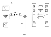
- FIG. 1 illustrates an EAS system 100.
- FIG. 1 describes a particular EAS system by way of example, it may be appreciated that the embodiments may operate with any EAS system as modified using the principles discussed herein.
- EAS system 100 may comprise EAS detection equipment, including an EAS marker detector 102 connected to a pedestal system via a communications medium 124.
- the pedestal system may comprise a pair of antenna pedestals, such as antenna pedestals 104 and 106, for example.
- the EAS detection equipment may be installed at an exit point of a controlled area, such as a retail store, for example.
- the EAS detection equipment may be used to create an interrogation zone 108 between antenna pedestals 104 and 106, for example.
- the interrogation zone may comprise an area receiving interrogation signals from EAS marker detector 102 via antennas 116a-d and 118a-b embedded within antenna pedestals 104 and 106.
- the interrogation signals may trigger a response from a security tag, such as an EAS security tag 120.
- the anti-theft functionality of EAS system 100 may be implemented through the interrogation and response interaction between EAS marker detector 102 and security tag 120.
- security tag 120 may comprise an EAS marker encased within a hard or soft outer shell.
- the marker may be any marker that emits a detectable signal when in interrogation zone 108.
- the marker may comprise, for example, a RF marker, a Radio-Frequency Identification (RFID) marker, an acoustically resonant magnetic EAS marker, a magnetic EAS marker, and so forth.
- RFID Radio-Frequency Identification
- An example of security tag 120 may comprise a Sensormatic® Ultra Strip@ EAS label made by Sensormatic Corporation. The embodiments are not limited with respect to the type of marker used for security tag 120 as long as it emits a detectable signal at the proper frequencies.
- security tag 120 may be designed to attach to an item to be monitored.
- tagged items may include an article of clothing, a Digital Video Disc (DVD) or Compact Disc (CD) jewel case, a movie rental container, packaging material, and so forth.
- DVD Digital Video Disc
- CD Compact Disc
- security tag 120 may enter interrogation zone 108 and receive one or more interrogation signals from EAS marker detector 102.
- Security tag 120 may receive the interrogation signals, and radiate a signal in response to the interrogation signals.
- the signal may be received by EAS marker detector 102.
- EAS marker detector 102 may determine whether to trigger an alarm based on the received signal.
- EAS system 100 may comprise EAS marker detector 102.
- EAS marker detector 102 may be configured to create an interrogation zone 108 between antenna pedestals 104 and 106 via the embedded antennas.
- EAS marker detector 102 may also be configured to detect the presence of security tag 120 within interrogation zone 108. Once security tag 120 is within interrogation zone 108, EAS marker detector 102 may determine whether to send an alarm signal to an alarm system, such as alarm system 114.
- EAS marker detector 102 may also operate as a data reader and writer for an RFID chip. EAS marker detector 102 may interrogate and read a RFID chip included in security tag 120, if any. EAS marker detector 102 may also write data into the RFID chip. This may be accomplished using any wireless communication link between EAS marker detector 102 and security tag 120, for example.
- EAS system 100 may comprise a processing system 110.
- Processing system 110 may comprise any device having a general purpose or dedicated processor, machine-readable memory and computer program segments stored in the memory to be executed by the processor.
- An example of a processing system may include a computer, server, personal digital assistant, switch, router, laptop, cell phone and so forth.
- Processing system 110 may be used to store and execute application programs, such as an alarm control system, inventory control system, and so forth.
- the inventor control system may track information such as merchandise identification, inventory, pricing, and other data.
- Processing system 110 may also be configured with the appropriate hardware and/or software to function as an RFID reader, similar to EAS marker detector 102. This may be useful for implementing inventory tracking functionality and anti-theft functionality of EAS system 100, as desired for a given implementation.
- processing system 110 may be in communication with EAS marker detector 102 via a communication link 124.
- communication link 124 may comprise a communication link over a wireless communication medium.
- the wireless communication medium may comprise one or more frequencies from the RF spectrum, for example.
- Communication link 124 may also represent a communication link over a wired communications medium as well.
- the wired communications medium may comprise twisted-pair wire, co-axial cable, Ethernet cables, and so forth. The embodiments for the communication link are not limited in this context.
- EAS system 100 may comprise an alarm system 114.
- Alarm system 114 may comprise any type of alarm system to provide an alarm in response to an alarm signal.
- the alarm signal may be received from any number of EAS components, such as processing system 110, EAS marker detector 102, deactivation system 122, and so forth.
- Alarm system 114 may comprise a user interface to program conditions or rules for triggering an alarm. Examples of the alarm may comprise an audible alarm such as a siren or bell, a visual alarm such as flashing lights, or a silent alarm.
- a silent alarm may comprise, for example, an inaudible alarm such as a message to a monitoring system for a security company. The message may be sent via a computer network, a telephone network, a paging network, and so forth.
- the embodiments are not limited in this context.
- EAS system 100 may comprise a deactivation system 122.
- Deactivation system 122 may be used to detect and deactivate a security tag, such as security tag 120.
- the term "deactivate" as used herein may refer to changing states for an EAS marker from an active state to an inactive state. While in the active state, the EAS marker may be configured to provide a response to the interrogation signals indicating the unauthorized presence of security tag 120 within interrogation zone 108. While in the inactive state, the EAS marker may be configured to provide no response to the interrogation signals, or provide a response to the interrogation signals indicating the authorized presence of security tag 120 within interrogation zone 108.
- FIG. 1 illustrates deactivation system 122 as connected to processing system 110, it may be appreciated that deactivation system 122 may be a separate or stand-alone system as well. The embodiments are not limited in this context. Deactivation system 122 may be discussed in more detail with reference to FIGS. 2-4.
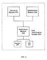
- FIG. 2 may illustrate a deactivation system in accordance with one embodiment.
- FIG. 2 may illustrate an EAS deactivation system 200.
- deactivation system 200 may be representative of, for example, deactivation system 122.
- Deactivation system 200 may comprise a detection module 202, a deactivation module 204, a notification module 206, a speaker 208 and one or more Light Emitting Diodes (LED) 210.
- LED Light Emitting Diodes
- deactivation system 200 may comprise a detection module 202.
- Detection module 202 may be configured to detect a security tag having an EAS marker.
- Detection module 202 may be any appropriate detection module configured to detect a given EAS marker.
- Detection module 202 may comprise transmit/receive coils and associated processing circuitry to create a detection zone to detect the presence of an EAS marker for an EAS security tag, such as EAS security tag 120.
- detection module 202 may send a signal to a deactivation module 204 to initiate the deactivation operation to deactivate the EAS marker, thereby rendering it undetectable by the EAS detection equipment when passing through the interrogation zone.
- deactivation system 200 may comprise a deactivation module 204.
- Deactivation module 204 may be configured to deactivate an EAS marker.
- Deactivation module 204 may be any appropriate deactivation module configured to deactivate a given EAS marker.
- deactivation module 204 may create a deactivation zone to deactivate the EAS marker.
- Deactivation module 204 may create the deactivation zone using a coil circuit to generate a magnetic field having an amplitude profile sufficient to deactivate a "magneto-mechanical" EAS marker.
- the term "amplitude profile" may refer to the peak amplitudes of a waveform over a given time interval.
- Magneto-mechanical EAS markers may include an active element and a bias element.
- the bias element When the bias element is magnetized in a certain manner, the resulting bias magnetic field applied to the active element causes the active element to be mechanically resonant at a predetermined frequency upon exposure to an interrogation signal which alternates at the predetermined frequency.
- the EAS detection equipment used with this type of EAS marker generates the interrogation signal and then detects the resonance of the EAS marker induced by the interrogation signal.
- the bias element may be degaussed by exposing the bias element to an alternating magnetic field that has an initial magnitude that is greater than the coercivity of the bias element, and then decays to zero over a time interval.
- the EAS marker's resonant frequency is substantially shifted from the predetermined interrogation signal frequency, and the EAS marker's response to the interrogation signal is at too low an amplitude for detection by the detecting apparatus.
- the EAS marker may be placed in an inactive state, thereby rendering it undetectable by the detecting apparatus.
- Detection module 202 and deactivation module 204 may work together to form a detection zone and deactivation zone, respectively, for deactivation system 200.
- the detection zone may have a greater range than the deactivation zone.
- deactivation module 204 may generate a deactivation zone within three inches of the coils used to create the deactivation zone. In this case, a user may need to bring the EAS marker within three inches of the surface of deactivation system 200.
- Detection module 202 may generate a detection zone that is greater than three inches, such as five or six inches, for example.
- Detection system 200 uses the greater range of the detection zone in conjunction with the deactivation zone to implement additional functionality for deactivation system 200.
- the detection and deactivation zones may be described in more detail with reference to FIG. 3.
- FIG. 3 illustrates a detection zone and a deactivation zone in accordance with one embodiment.
- FIG. 3 illustrates two-dimensional representation of a detection zone and deactivation zone produced by a deactivation system, such as deactivation system 200, for example.
- a deactivation system such as deactivation system 200
- FIG. 3 illustrates a two-dimensional representation of the detection zone and deactivation zone, it may be appreciated that the actual detection zone and deactivation zone may have three dimensions when actually implemented.
- Deactivation system 200 may create a deactivation zone 302 having a deactivation zone perimeter 302A.
- Deactivation system 200 may also create a detection zone 304 having a detection zone perimeter 304A.
- detection zone 304 may have a greater range than deactivation zone 302.
- deactivation zone perimeter 302A of deactivation zone 302 may fit within detection zone perimeter 304A of detection zone 304. Since deactivation zone perimeter 302A is less than detection zone perimeter 304A, overlapping deactivation zone 302 and detection zone 304 may form an expanded zone 306 between deactivation zone perimeter 302A and detection zone perimeter 304A.
- Expanded zone 306 may provide a number of advantages for deactivation system 200.
- deactivation system 200 may use expanded zone 306 to make a user aware that an EAS security tag was detected but not within the specified deactivation zone.
- the deactivation system may alert the user that they have properly deactivated the EAS security tag.
- the deactivation system may alert the user that the marker was detected, but not properly deactivated. The embodiments are not limited in this context.
- detection module 202 may send a notification signal to notification module 206 to indicate the presence of the EAS marker within the detection zone.
- detection module 202 may determine whether the EAS marker is in an active state or an inactive state, and may send an appropriate notification signal to notification module 206 in accordance with the determination.
- notification module 206 may receive the notification signals from detection module 202. Notification module 206 may process the notification signals and generate one or more audio signals to represent audio information for reproduction by speaker 208. Notification module 206 may also generate one or more visual signals to represent visual indicators for reproduction by LED 210. By using different audio and visual signals, a user may be given instant feedback on the current state of security tag 120. For example, a first set of audio and/or visual signals may represent the presence of an active EAS marker within expanded zone 306. In another example, a second set of audio and/or visual signals may represent the presence of an inactive EAS marker within expanded zone 306. In yet another example, a third set of audio and/or visual signals may represent an active EAS marker exiting expanded zone 306. The number and type of audio and visual signals are not limited in this context.
- FIG. 4 may include a particular programming logic, it can be appreciated that the programming logic merely provides an example of how the general functionality described herein can be implemented. Further, the given programming logic does not necessarily have to be executed in the order presented unless otherwise indicated. In addition, although the given programming logic may be described herein as being implemented in the above-referenced modules, it can be appreciated that the programming logic may be implemented anywhere within the system and still fall within the scope of the embodiments.
- FIG. 4 illustrates a programming logic for a deactivation system in accordance with one embodiment.
- FIG. 4 illustrates a programming logic 400.
- Programming logic 400 may be executed by, for example, deactivation system 200.
- a detection zone having a first perimeter may be generated at block 402.
- a deactivation zone having a second perimeter may be generated at block 404.
- the range of the second perimeter may be less than the first perimeter to form an expanded zone between the first and second perimeters.
- An EAS marker may be detected within the expanded zone at block 406.
- a state may be determined for the EAS marker at block 408.
- a notification signal may be generated in accordance with the determination made at block 408.
- the EAS marker may have an active state.
- a first notification signal may be generated to indicate that the EAS marker is within the expanded zone in an active state. This may be useful, for example, to inform a user that there is a security tag near deactivation system 200, but not close enough to be deactivated. The user may be quickly informed of this information through the use of a unique set of audible sounds and/or visual indicators. Consequently, the first notification signal may comprise a first audio signal and a first visual signal to provide this unique set of indicators.
- the EAS marker may have an inactive state.
- a second notification may be generated to indicate that the EAS marker is within the expanded zone in an inactive state. This may be useful, for example, to inform a user that the security tag has already been deactivated without having to bring the EAS marker within the more restrictive range of the deactivation zone. The user may be informed of this information using another unique set of audible sounds and/or visual indicators. Consequently, the second notification signal may comprise a second audio signal and a second visual signal to provide this unique set of indicators.
- a user may be informed that an active EAS marker has entered the expanded zone, and is exiting the expanded zone without having been deactivated.
- a third notification signal may be generated to indicate that the EAS marker is exiting the expanded zone in an active state.
- a unique set of audio sounds and/or visual indicators may be used to convey this information to a user.
- a user may be informed that an active EAS marker has entered the deactivation zone and has been properly deactivated.
- a user may bring the EAS marker within the deactivation zone.
- the magnetic field of the deactivation zone may deactivate the EAS marker by changing the EAS marker from an active state to an inactive state.
- the predetermined amount of time may vary in accordance with the type of deactivation zone created by the deactivation module.
- a fourth notification signal may be generated to indicate that the EAS marker has been properly deactivated.
- the fourth notification signal may be used to reproduce a unique set of audio sounds and/or visual indicators to convey this information to a user.
- first notification signal “second notification signal, “third notification signal,” “fourth notification signal”, and related terminology, are used to distinguish between different types of notification signals, and do not necessarily refer to a specific temporal sequence of signals.
- deactivation system 200 may be implemented as part of an EAS system for a retail store selling DVDs.
- the retail store may tag the jewel case of each DVD with security tag 120 having an EAS marker.
- the jewel case for each DVD may be sourced tagged or retail tagged.
- An example of deactivator system 200 may comprise the AMB-2010 Deactivator made by Sensormatic Corporation, although the embodiments are not limited in this context.
- deactivation system 200 is implemented at a Point Of Sale (POS) terminal in the form of a table top implementation or flush mounted with the surface of the sales counter.
- Deactivation system 200 may provide a deactivation zone having a deactivation height of three inches or 7.6 centimeters (cm).
- deactivation system 200 When a customer presents an item to a sales clerk, the sales clerk may deactivate security tag 120 attached to the item using deactivation system 200.
- detection module 202 may send an interrogation signal to the active element of the EAS marker within security tag 120 and then detects the resonance of the EAS marker induced by the interrogation signal.
- Deactivation system 200 may provide a unique set of audible and visual indicators to quickly represent different events to the sales clerk based on the resonance signal from the EAS marker.
- Detection module 202 may send a notification signal to notification module 206 that an active EAS marker has been detected within detection zone 304 in general, and expanded zone 306 in particular.
- Notification module 206 may generate a unique tone to represent this event via an audio signal sent to speaker 208.
- the unique tone may comprise, for example, a 100 millisecond (msec) pulsed tone that is continuous as long as the active EAS marker remains in expanded zone 306.
- notification module 206 may generate a visual indicator signal for a first LED 210 labeled "Detect" on the surface of deactivation system 200.
- the Detect LED 210 may light up with a specific color to indicate an active EAS marker in expanded zone 306. For example, Detect LED 210 may display the color red to notify the user of this event.
- Detection module 202 may detect the entry and exit of the active EAS marker, and sends a notification signal to notification module 206.
- Notification module 206 may generate a unique tone to represent this event via an audio signal sent to speaker 208.
- the unique tone may comprise, for example, a 100 millisecond (msec) pulsed tone that continues for two seconds after the EAS marker has passed outside of detection zone 304.
- notification module 206 may generate a visual indicator signal for Detect LED 210 by having it flash red at a predetermined rate to notify the user of this event.
- Detection module 202 may send a notification signal to notification module 206 that an inactive EAS marker has been detected within detection zone 304 in general, and expanded zone 306 in particular.
- Notification module 206 may generate a visual indicator signal to display the color amber via Detect LED 210. The amber color may notify the user that security tag 120 has been properly deactivated.
- An optional audible signal may also be provided via speaker 208 if desired for a given implementation.
- deactivation module 204 may continuously generate deactivation zone 302 thereby obviating the need for the signal from detection module 202. In any event, deactivation module 204 may generate deactivation zone 302.
- deactivation zone 302 may degauss the bias element of the EAS marker by exposing the bias element to an alternating magnetic field that has an initial magnitude that is greater than the coercivity of the bias element, and then decays to zero over a time interval.
- the EAS marker's resonant frequency is substantially shifted from the predetermined interrogation signal frequency, and the EAS marker's response to the interrogation signal is at too low an amplitude for detection by the detecting apparatus.
- the EAS marker may be changed from an active state to an inactive state, thereby rendering it undetectable by the detecting apparatus.
- detection module 202 may send a notification signal to notification module 206.
- Notification module 206 may provide an audible tone via speaker 208, such as a single one second tone or beep.
- Notification module 206 may also provide a visual indicator via a LED 210 labeled "Deactivation.” The Deactivation LED 210 may flash or hold an amber color to indicate to the sales clerk that security tag 120 has been properly deactivated.
- detection module 202 may send a notification signal to notification module 206 to light up or display a color such as green on a LED 210 labeled "Ready.”
- the Ready LED 210 may indicate to the sales clerk that deactivation system 200 is ready for use and is currently detecting no EAS markers within detection zone 304.
- the embodiments may be implemented using an architecture that may vary in accordance with any number of factors, such as desired computational rate, power levels, heat tolerances, processing cycle budget, input data rates, output data rates, memory resources, data bus speeds and other performance constraints.
- one embodiment may be implemented using software executed by a processor.
- the processor may be a general-purpose or dedicated processor, such as a processor made by Intel? Corporation, for example.
- the software may comprise computer program code segments, programming logic, instructions or data.
- the software may be stored on a medium accessible by a machine, computer or other processing system.
- acceptable mediums may include computer-readable mediums such as read-only memory (ROM), random-access memory (RAM), Programmable ROM (PROM), Erasable PROM (EPROM), magnetic disk, optical disk, and so forth.
- the medium may store programming instructions in a compressed and/or encrypted format, as well as instructions that may have to be compiled or installed by an installer before being executed by the processor.
- one embodiment may be implemented as dedicated hardware, such as an Application Specific Integrated Circuit (ASIC), Programmable Logic Device (PLD) or Digital Signal Processor (DSP) and accompanying hardware structures.
- ASIC Application Specific Integrated Circuit
- PLD Programmable Logic Device
- DSP Digital Signal Processor
- one embodiment may be implemented by any combination of programmed general-purpose computer components and custom hardware components. The embodiments are not limited in this context.
Landscapes
- Physics & Mathematics (AREA)
- Engineering & Computer Science (AREA)
- Automation & Control Theory (AREA)
- Computer Security & Cryptography (AREA)
- Electromagnetism (AREA)
- General Physics & Mathematics (AREA)
- Burglar Alarm Systems (AREA)
- Radar Systems Or Details Thereof (AREA)
Applications Claiming Priority (2)
| Application Number | Priority Date | Filing Date | Title |
|---|---|---|---|
| US10/764,007 US7109866B2 (en) | 2004-01-23 | 2004-01-23 | Electronic article surveillance marker deactivator using an expanded detection zone |
| US764007 | 2004-01-23 |
Publications (3)
| Publication Number | Publication Date |
|---|---|
| EP1557806A2 true EP1557806A2 (de) | 2005-07-27 |
| EP1557806A3 EP1557806A3 (de) | 2005-08-17 |
| EP1557806B1 EP1557806B1 (de) | 2015-10-14 |
Family
ID=34634619
Family Applications (1)
| Application Number | Title | Priority Date | Filing Date |
|---|---|---|---|
| EP05000373.0A Expired - Lifetime EP1557806B1 (de) | 2004-01-23 | 2005-01-11 | Warensicherungsetikettendeaktivator unter Verwendung von einem erweiterten Detektionsgebiet |
Country Status (4)
| Country | Link |
|---|---|
| US (1) | US7109866B2 (de) |
| EP (1) | EP1557806B1 (de) |
| CA (1) | CA2491330C (de) |
| ES (1) | ES2552810T3 (de) |
Cited By (6)
| Publication number | Priority date | Publication date | Assignee | Title |
|---|---|---|---|---|
| WO2007021648A3 (en) * | 2005-08-10 | 2007-05-03 | Rockwell Automation Tech Inc | Enhanced controller utilizing rfid technology |
| WO2008153703A3 (en) * | 2007-05-30 | 2009-03-05 | Sensormatic Electronics Corp | Electronics eas tag detection and method |
| US7994919B2 (en) | 2004-11-10 | 2011-08-09 | Rockwell Automation Technologies, Inc. | Systems and methods that integrate radio frequency identification (RFID) technology with agent-based control systems |
| US7997475B2 (en) | 2004-11-10 | 2011-08-16 | Rockwell Automation Technologies, Inc. | Systems and methods that integrate radio frequency identification (RFID) technology with industrial controllers |
| US8025227B2 (en) | 2005-09-30 | 2011-09-27 | Rockwell Automation Technologies, Inc. | Access to distributed databases via pointer stored in RFID tag |
| US8152053B2 (en) | 2005-09-08 | 2012-04-10 | Rockwell Automation Technologies, Inc. | RFID architecture in an industrial controller environment |
Families Citing this family (5)
| Publication number | Priority date | Publication date | Assignee | Title |
|---|---|---|---|---|
| EP2287817B1 (de) * | 2002-02-01 | 2012-05-23 | Datalogic Adc, Inc. | Systeme und Verfahren zur Datenlesung und EAS-Etikettenerkennung und Deaktivierung beim Abmelden aus dem Einzelhandel |
| US20070115124A1 (en) * | 2005-11-21 | 2007-05-24 | Cyril Brignone | Determining a state for object identified by an RFID tag |
| US7733290B2 (en) * | 2005-12-19 | 2010-06-08 | Sensormatic Electronics, LLC | Merchandise surveillance system antenna and method |
| US7791485B2 (en) * | 2007-08-22 | 2010-09-07 | International Business Machines Corporation | Decommissioning bin for automatic decommissioning of electronic tags |
| US8450997B2 (en) * | 2009-04-28 | 2013-05-28 | Brown University | Electromagnetic position and orientation sensing system |
Family Cites Families (7)
| Publication number | Priority date | Publication date | Assignee | Title |
|---|---|---|---|---|
| US3938044A (en) | 1973-11-14 | 1976-02-10 | Lichtblau G J | Antenna apparatus for an electronic security system |
| US4565996A (en) * | 1984-02-06 | 1986-01-21 | Mrs. Lawrence Israel | Range limited coherent frequency doppler surveillance system |
| US5341125A (en) * | 1992-01-15 | 1994-08-23 | Sensormatic Electronics Corporation | Deactivating device for deactivating EAS dual status magnetic tags |
| US5917412A (en) * | 1997-05-21 | 1999-06-29 | Sensormatic Electronics Corporation | Deactivation device with biplanar deactivation |
| US6028518A (en) * | 1998-06-04 | 2000-02-22 | Checkpoint Systems, Inc. | System for verifying attachment of an EAS marker to an article after tagging |
| US6400273B1 (en) * | 2000-05-05 | 2002-06-04 | Sensormatic Electronics Corporation | EAS system with wide exit coverage and reduced over-range |
| US6837428B2 (en) * | 2001-03-02 | 2005-01-04 | Mike Lee | Self-checkout apparatus |
-
2004
- 2004-01-23 US US10/764,007 patent/US7109866B2/en not_active Expired - Lifetime
- 2004-12-30 CA CA002491330A patent/CA2491330C/en not_active Expired - Lifetime
-
2005
- 2005-01-11 EP EP05000373.0A patent/EP1557806B1/de not_active Expired - Lifetime
- 2005-01-11 ES ES05000373.0T patent/ES2552810T3/es not_active Expired - Lifetime
Cited By (10)
| Publication number | Priority date | Publication date | Assignee | Title |
|---|---|---|---|---|
| US7994919B2 (en) | 2004-11-10 | 2011-08-09 | Rockwell Automation Technologies, Inc. | Systems and methods that integrate radio frequency identification (RFID) technology with agent-based control systems |
| US7997475B2 (en) | 2004-11-10 | 2011-08-16 | Rockwell Automation Technologies, Inc. | Systems and methods that integrate radio frequency identification (RFID) technology with industrial controllers |
| US8384544B2 (en) | 2004-11-10 | 2013-02-26 | Rockwell Automation Technologies, Inc. | Systems and methods that integrate radio frequency identification (RFID) technology with agent-based control systems |
| WO2007021648A3 (en) * | 2005-08-10 | 2007-05-03 | Rockwell Automation Tech Inc | Enhanced controller utilizing rfid technology |
| JP2009505229A (ja) * | 2005-08-10 | 2009-02-05 | ロックウェル オートメーション テクノロジーズ, インコーポレーテッド | Rfid技術を使用する向上させたコントローラ |
| US8260948B2 (en) | 2005-08-10 | 2012-09-04 | Rockwell Automation Technologies, Inc. | Enhanced controller utilizing RFID technology |
| US8152053B2 (en) | 2005-09-08 | 2012-04-10 | Rockwell Automation Technologies, Inc. | RFID architecture in an industrial controller environment |
| US8025227B2 (en) | 2005-09-30 | 2011-09-27 | Rockwell Automation Technologies, Inc. | Access to distributed databases via pointer stored in RFID tag |
| WO2008153703A3 (en) * | 2007-05-30 | 2009-03-05 | Sensormatic Electronics Corp | Electronics eas tag detection and method |
| CN101681544B (zh) * | 2007-05-30 | 2015-02-18 | 传感电子公司 | 电子eas标签检测和方法 |
Also Published As
| Publication number | Publication date |
|---|---|
| EP1557806B1 (de) | 2015-10-14 |
| CA2491330A1 (en) | 2005-07-23 |
| US20050162275A1 (en) | 2005-07-28 |
| CA2491330C (en) | 2009-08-25 |
| EP1557806A3 (de) | 2005-08-17 |
| US7109866B2 (en) | 2006-09-19 |
| ES2552810T3 (es) | 2015-12-02 |
Similar Documents
| Publication | Publication Date | Title |
|---|---|---|
| US7042359B2 (en) | Method and apparatus to detect a plurality of security tags | |
| US7495564B2 (en) | Systems and methods for data reading and EAS tag sensing and deactivating at retail checkout | |
| US20140035748A1 (en) | Electronic article surveillance systems, apparatus, and methods | |
| AU2020215046B2 (en) | Smart alarm management | |
| CN102947729A (zh) | 用于减少金属检测系统错误警报的方法 | |
| CA2491330C (en) | Electronic article surveillance marker deactivator using an expanded detection zone | |
| KR20150128964A (ko) | 보안 태그 분리의 검증을 위한 시스템들 및 방법들 | |
| AU2008347163A1 (en) | Electronic article surveillance system neural network minimizing false alarms and failures to deactivate | |
| JPS63502461A (ja) | 警報札 | |
| US6744366B2 (en) | Method and apparatus of obtaining security tag operation using local magnetic marker | |
| CN101223557B (zh) | 用于射频识别和电子商品防盗的装置和方法 | |
| US20040036577A1 (en) | Anti-theft device and method for use in products with electric or electronic components therein | |
| CN102105916A (zh) | 具有多个标签检测能力的电子商品防盗去激活器及其方法 | |
| US20070046470A1 (en) | Hybrid Acousto-Magnetic Radio Frequency Transceiver Device | |
| HK1079321A (en) | Electronic article surveillance marker deactivator using an expanded detection zone | |
| HK1079321B (en) | Electronic article surveillance marker deactivator using an expanded detection zone | |
| JP2002529831A (ja) | 小売店舗からの商品の窃盗を阻止するためのセキュリティシステム | |
| US7026934B2 (en) | Method and apparatus to prevent unauthorized removal of a pedestal from a base | |
| US11568726B2 (en) | Systems and methods for deactivation frequency reduction using a transformer | |
| US9472074B2 (en) | Security tag alerting for continuous movement | |
| AU2013273749B2 (en) | Electronic article surveillance system neural network minimizing false alarms and failures to deactivate | |
| Bhatt et al. | A Comparative Study of Electronic Article Surveillance (EAS) System | |
| KR20070001314A (ko) | Rfid 기술을 이용한 물품 도난 방지 시스템 | |
| WO1990003623A1 (en) | System for verification of de-activation of anti-theft markers | |
| HK1073519A (en) | Method and apparatus to detect a plurality of security tags |
Legal Events
| Date | Code | Title | Description |
|---|---|---|---|
| PUAI | Public reference made under article 153(3) epc to a published international application that has entered the european phase |
Free format text: ORIGINAL CODE: 0009012 |
|
| PUAL | Search report despatched |
Free format text: ORIGINAL CODE: 0009013 |
|
| AK | Designated contracting states |
Kind code of ref document: A2 Designated state(s): AT BE BG CH CY CZ DE DK EE ES FI FR GB GR HU IE IS IT LI LT LU MC NL PL PT RO SE SI SK TR |
|
| AX | Request for extension of the european patent |
Extension state: AL BA HR LV MK YU |
|
| AK | Designated contracting states |
Kind code of ref document: A3 Designated state(s): AT BE BG CH CY CZ DE DK EE ES FI FR GB GR HU IE IS IT LI LT LU MC NL PL PT RO SE SI SK TR |
|
| AX | Request for extension of the european patent |
Extension state: AL BA HR LV MK YU |
|
| 17P | Request for examination filed |
Effective date: 20050830 |
|
| REG | Reference to a national code |
Ref country code: HK Ref legal event code: DE Ref document number: 1079321 Country of ref document: HK |
|
| AKX | Designation fees paid |
Designated state(s): AT BE BG CH CY CZ DE DK EE ES FI FR GB GR HU IE IS IT LI LT LU MC NL PL PT RO SE SI SK TR |
|
| 17Q | First examination report despatched |
Effective date: 20070820 |
|
| RAP1 | Party data changed (applicant data changed or rights of an application transferred) |
Owner name: SENSORMATIC ELECTRONICS, LLC |
|
| RAP1 | Party data changed (applicant data changed or rights of an application transferred) |
Owner name: TYCO FIRE & SECURITY GMBH |
|
| GRAP | Despatch of communication of intention to grant a patent |
Free format text: ORIGINAL CODE: EPIDOSNIGR1 |
|
| INTG | Intention to grant announced |
Effective date: 20150630 |
|
| GRAS | Grant fee paid |
Free format text: ORIGINAL CODE: EPIDOSNIGR3 |
|
| GRAA | (expected) grant |
Free format text: ORIGINAL CODE: 0009210 |
|
| AK | Designated contracting states |
Kind code of ref document: B1 Designated state(s): AT BE BG CH CY CZ DE DK EE ES FI FR GB GR HU IE IS IT LI LT LU MC NL PL PT RO SE SI SK TR |
|
| REG | Reference to a national code |
Ref country code: GB Ref legal event code: FG4D |
|
| REG | Reference to a national code |
Ref country code: AT Ref legal event code: REF Ref document number: 755635 Country of ref document: AT Kind code of ref document: T Effective date: 20151015 Ref country code: CH Ref legal event code: EP |
|
| REG | Reference to a national code |
Ref country code: IE Ref legal event code: FG4D |
|
| REG | Reference to a national code |
Ref country code: DE Ref legal event code: R096 Ref document number: 602005047670 Country of ref document: DE |
|
| REG | Reference to a national code |
Ref country code: ES Ref legal event code: FG2A Ref document number: 2552810 Country of ref document: ES Kind code of ref document: T3 Effective date: 20151202 |
|
| REG | Reference to a national code |
Ref country code: FR Ref legal event code: PLFP Year of fee payment: 12 |
|
| REG | Reference to a national code |
Ref country code: NL Ref legal event code: MP Effective date: 20151014 |
|
| REG | Reference to a national code |
Ref country code: LT Ref legal event code: MG4D |
|
| REG | Reference to a national code |
Ref country code: AT Ref legal event code: MK05 Ref document number: 755635 Country of ref document: AT Kind code of ref document: T Effective date: 20151014 |
|
| PG25 | Lapsed in a contracting state [announced via postgrant information from national office to epo] |
Ref country code: NL Free format text: LAPSE BECAUSE OF FAILURE TO SUBMIT A TRANSLATION OF THE DESCRIPTION OR TO PAY THE FEE WITHIN THE PRESCRIBED TIME-LIMIT Effective date: 20151014 Ref country code: IT Free format text: LAPSE BECAUSE OF FAILURE TO SUBMIT A TRANSLATION OF THE DESCRIPTION OR TO PAY THE FEE WITHIN THE PRESCRIBED TIME-LIMIT Effective date: 20151014 Ref country code: IS Free format text: LAPSE BECAUSE OF FAILURE TO SUBMIT A TRANSLATION OF THE DESCRIPTION OR TO PAY THE FEE WITHIN THE PRESCRIBED TIME-LIMIT Effective date: 20160214 Ref country code: LT Free format text: LAPSE BECAUSE OF FAILURE TO SUBMIT A TRANSLATION OF THE DESCRIPTION OR TO PAY THE FEE WITHIN THE PRESCRIBED TIME-LIMIT Effective date: 20151014 |
|
| PG25 | Lapsed in a contracting state [announced via postgrant information from national office to epo] |
Ref country code: SE Free format text: LAPSE BECAUSE OF FAILURE TO SUBMIT A TRANSLATION OF THE DESCRIPTION OR TO PAY THE FEE WITHIN THE PRESCRIBED TIME-LIMIT Effective date: 20151014 Ref country code: PT Free format text: LAPSE BECAUSE OF FAILURE TO SUBMIT A TRANSLATION OF THE DESCRIPTION OR TO PAY THE FEE WITHIN THE PRESCRIBED TIME-LIMIT Effective date: 20160215 Ref country code: GR Free format text: LAPSE BECAUSE OF FAILURE TO SUBMIT A TRANSLATION OF THE DESCRIPTION OR TO PAY THE FEE WITHIN THE PRESCRIBED TIME-LIMIT Effective date: 20160115 Ref country code: AT Free format text: LAPSE BECAUSE OF FAILURE TO SUBMIT A TRANSLATION OF THE DESCRIPTION OR TO PAY THE FEE WITHIN THE PRESCRIBED TIME-LIMIT Effective date: 20151014 Ref country code: FI Free format text: LAPSE BECAUSE OF FAILURE TO SUBMIT A TRANSLATION OF THE DESCRIPTION OR TO PAY THE FEE WITHIN THE PRESCRIBED TIME-LIMIT Effective date: 20151014 Ref country code: BE Free format text: LAPSE BECAUSE OF NON-PAYMENT OF DUE FEES Effective date: 20160131 Ref country code: PL Free format text: LAPSE BECAUSE OF FAILURE TO SUBMIT A TRANSLATION OF THE DESCRIPTION OR TO PAY THE FEE WITHIN THE PRESCRIBED TIME-LIMIT Effective date: 20151014 |
|
| REG | Reference to a national code |
Ref country code: DE Ref legal event code: R097 Ref document number: 602005047670 Country of ref document: DE |
|
| PG25 | Lapsed in a contracting state [announced via postgrant information from national office to epo] |
Ref country code: CZ Free format text: LAPSE BECAUSE OF FAILURE TO SUBMIT A TRANSLATION OF THE DESCRIPTION OR TO PAY THE FEE WITHIN THE PRESCRIBED TIME-LIMIT Effective date: 20151014 |
|
| PLBE | No opposition filed within time limit |
Free format text: ORIGINAL CODE: 0009261 |
|
| STAA | Information on the status of an ep patent application or granted ep patent |
Free format text: STATUS: NO OPPOSITION FILED WITHIN TIME LIMIT |
|
| PG25 | Lapsed in a contracting state [announced via postgrant information from national office to epo] |
Ref country code: SK Free format text: LAPSE BECAUSE OF FAILURE TO SUBMIT A TRANSLATION OF THE DESCRIPTION OR TO PAY THE FEE WITHIN THE PRESCRIBED TIME-LIMIT Effective date: 20151014 Ref country code: LU Free format text: LAPSE BECAUSE OF FAILURE TO SUBMIT A TRANSLATION OF THE DESCRIPTION OR TO PAY THE FEE WITHIN THE PRESCRIBED TIME-LIMIT Effective date: 20160111 Ref country code: RO Free format text: LAPSE BECAUSE OF FAILURE TO SUBMIT A TRANSLATION OF THE DESCRIPTION OR TO PAY THE FEE WITHIN THE PRESCRIBED TIME-LIMIT Effective date: 20151014 Ref country code: DK Free format text: LAPSE BECAUSE OF FAILURE TO SUBMIT A TRANSLATION OF THE DESCRIPTION OR TO PAY THE FEE WITHIN THE PRESCRIBED TIME-LIMIT Effective date: 20151014 Ref country code: EE Free format text: LAPSE BECAUSE OF FAILURE TO SUBMIT A TRANSLATION OF THE DESCRIPTION OR TO PAY THE FEE WITHIN THE PRESCRIBED TIME-LIMIT Effective date: 20151014 |
|
| REG | Reference to a national code |
Ref country code: CH Ref legal event code: PL |
|
| 26N | No opposition filed |
Effective date: 20160715 |
|
| PG25 | Lapsed in a contracting state [announced via postgrant information from national office to epo] |
Ref country code: MC Free format text: LAPSE BECAUSE OF FAILURE TO SUBMIT A TRANSLATION OF THE DESCRIPTION OR TO PAY THE FEE WITHIN THE PRESCRIBED TIME-LIMIT Effective date: 20151014 |
|
| PG25 | Lapsed in a contracting state [announced via postgrant information from national office to epo] |
Ref country code: LI Free format text: LAPSE BECAUSE OF NON-PAYMENT OF DUE FEES Effective date: 20160131 Ref country code: CH Free format text: LAPSE BECAUSE OF NON-PAYMENT OF DUE FEES Effective date: 20160131 |
|
| REG | Reference to a national code |
Ref country code: IE Ref legal event code: MM4A |
|
| PG25 | Lapsed in a contracting state [announced via postgrant information from national office to epo] |
Ref country code: SI Free format text: LAPSE BECAUSE OF FAILURE TO SUBMIT A TRANSLATION OF THE DESCRIPTION OR TO PAY THE FEE WITHIN THE PRESCRIBED TIME-LIMIT Effective date: 20151014 |
|
| PG25 | Lapsed in a contracting state [announced via postgrant information from national office to epo] |
Ref country code: BE Free format text: LAPSE BECAUSE OF FAILURE TO SUBMIT A TRANSLATION OF THE DESCRIPTION OR TO PAY THE FEE WITHIN THE PRESCRIBED TIME-LIMIT Effective date: 20151014 |
|
| REG | Reference to a national code |
Ref country code: FR Ref legal event code: PLFP Year of fee payment: 13 |
|
| PG25 | Lapsed in a contracting state [announced via postgrant information from national office to epo] |
Ref country code: IE Free format text: LAPSE BECAUSE OF NON-PAYMENT OF DUE FEES Effective date: 20160111 |
|
| REG | Reference to a national code |
Ref country code: FR Ref legal event code: PLFP Year of fee payment: 14 |
|
| PG25 | Lapsed in a contracting state [announced via postgrant information from national office to epo] |
Ref country code: CY Free format text: LAPSE BECAUSE OF FAILURE TO SUBMIT A TRANSLATION OF THE DESCRIPTION OR TO PAY THE FEE WITHIN THE PRESCRIBED TIME-LIMIT Effective date: 20151014 Ref country code: HU Free format text: LAPSE BECAUSE OF FAILURE TO SUBMIT A TRANSLATION OF THE DESCRIPTION OR TO PAY THE FEE WITHIN THE PRESCRIBED TIME-LIMIT; INVALID AB INITIO Effective date: 20050111 |
|
| PG25 | Lapsed in a contracting state [announced via postgrant information from national office to epo] |
Ref country code: TR Free format text: LAPSE BECAUSE OF FAILURE TO SUBMIT A TRANSLATION OF THE DESCRIPTION OR TO PAY THE FEE WITHIN THE PRESCRIBED TIME-LIMIT Effective date: 20151014 |
|
| PG25 | Lapsed in a contracting state [announced via postgrant information from national office to epo] |
Ref country code: BG Free format text: LAPSE BECAUSE OF FAILURE TO SUBMIT A TRANSLATION OF THE DESCRIPTION OR TO PAY THE FEE WITHIN THE PRESCRIBED TIME-LIMIT Effective date: 20151014 |
|
| REG | Reference to a national code |
Ref country code: ES Ref legal event code: PC2A Owner name: SENSORMATIC ELECTRONICS, LLC Effective date: 20190201 |
|
| REG | Reference to a national code |
Ref country code: DE Ref legal event code: R082 Ref document number: 602005047670 Country of ref document: DE Representative=s name: HAFNER & KOHL PATENTANWALTSKANZLEI RECHTSANWAL, DE Ref country code: DE Ref legal event code: R081 Ref document number: 602005047670 Country of ref document: DE Owner name: SENSORMATIC ELECTRONICS, LLC, BOCA RATON, US Free format text: FORMER OWNER: TYCO FIRE & SECURITY GMBH, NEUHAUSEN AM RHEINFALL, CH Ref country code: DE Ref legal event code: R082 Ref document number: 602005047670 Country of ref document: DE Representative=s name: HAFNER & KOHL PATENT- UND RECHTSANWAELTE PARTN, DE Ref country code: DE Ref legal event code: R082 Ref document number: 602005047670 Country of ref document: DE Representative=s name: HAFNER & KOHL PARTMBB, DE |
|
| REG | Reference to a national code |
Ref country code: GB Ref legal event code: 732E Free format text: REGISTERED BETWEEN 20191205 AND 20191211 |
|
| PGFP | Annual fee paid to national office [announced via postgrant information from national office to epo] |
Ref country code: ES Payment date: 20240209 Year of fee payment: 20 |
|
| PGFP | Annual fee paid to national office [announced via postgrant information from national office to epo] |
Ref country code: DE Payment date: 20240129 Year of fee payment: 20 Ref country code: GB Payment date: 20240123 Year of fee payment: 20 |
|
| PGFP | Annual fee paid to national office [announced via postgrant information from national office to epo] |
Ref country code: FR Payment date: 20240125 Year of fee payment: 20 |
|
| REG | Reference to a national code |
Ref country code: DE Ref legal event code: R071 Ref document number: 602005047670 Country of ref document: DE |
|
| REG | Reference to a national code |
Ref country code: ES Ref legal event code: FD2A Effective date: 20250124 |
|
| REG | Reference to a national code |
Ref country code: GB Ref legal event code: PE20 Expiry date: 20250110 |
|
| PG25 | Lapsed in a contracting state [announced via postgrant information from national office to epo] |
Ref country code: ES Free format text: LAPSE BECAUSE OF EXPIRATION OF PROTECTION Effective date: 20250112 |
|
| PG25 | Lapsed in a contracting state [announced via postgrant information from national office to epo] |
Ref country code: GB Free format text: LAPSE BECAUSE OF EXPIRATION OF PROTECTION Effective date: 20250110 |