EP1557643B2 - Angle detector - Google Patents
Angle detector Download PDFInfo
- Publication number
- EP1557643B2 EP1557643B2 EP05000439.9A EP05000439A EP1557643B2 EP 1557643 B2 EP1557643 B2 EP 1557643B2 EP 05000439 A EP05000439 A EP 05000439A EP 1557643 B2 EP1557643 B2 EP 1557643B2
- Authority
- EP
- European Patent Office
- Prior art keywords
- attachment
- lugs
- rotary encoder
- rotation angle
- measurement device
- Prior art date
- Legal status (The legal status is an assumption and is not a legal conclusion. Google has not performed a legal analysis and makes no representation as to the accuracy of the status listed.)
- Expired - Lifetime
Links
- 230000008878 coupling Effects 0.000 claims abstract description 21
- 238000010168 coupling process Methods 0.000 claims abstract description 21
- 238000005859 coupling reaction Methods 0.000 claims abstract description 21
- 238000005259 measurement Methods 0.000 claims description 11
- 229910000639 Spring steel Inorganic materials 0.000 claims description 4
- 230000006835 compression Effects 0.000 claims description 2
- 238000007906 compression Methods 0.000 claims description 2
- 230000001419 dependent effect Effects 0.000 claims 1
- 239000013013 elastic material Substances 0.000 claims 1
- 238000009434 installation Methods 0.000 description 3
- 239000012858 resilient material Substances 0.000 description 2
- 230000001133 acceleration Effects 0.000 description 1
- 238000005452 bending Methods 0.000 description 1
- 238000010276 construction Methods 0.000 description 1
- 238000000034 method Methods 0.000 description 1
- 239000013589 supplement Substances 0.000 description 1
Images


Classifications
-
- G—PHYSICS
- G01—MEASURING; TESTING
- G01D—MEASURING NOT SPECIALLY ADAPTED FOR A SPECIFIC VARIABLE; ARRANGEMENTS FOR MEASURING TWO OR MORE VARIABLES NOT COVERED IN A SINGLE OTHER SUBCLASS; TARIFF METERING APPARATUS; MEASURING OR TESTING NOT OTHERWISE PROVIDED FOR
- G01D11/00—Component parts of measuring arrangements not specially adapted for a specific variable
- G01D11/30—Supports specially adapted for an instrument; Supports specially adapted for a set of instruments
Definitions
- the invention relates to a rotational angle measuring device according to the preamble of claim 1.
- the known rotation angle measuring device consists of a rotary encoder, which is rotationally connected via a stator coupling with a stationary part of a drive to be measured.
- the housing of the rotary encoder by means of the stator coupling is rotationally rigidly connected to an actuator housing of the drive device in order to avoid a Winkelmesshab.
- the angle measurement error caused by the stator coupling should be less than the measurement accuracy of the encoder.
- measuring devices which measure mechanical measured variables such as the angular velocity, the angular acceleration or the torque, can also be coupled to the stator of a drive device by means of this stator coupling.
- the stator coupling has a torque arm, which has the actual task of anti-rotation.
- This consists of an annular base plate, are provided on the two lugs for mounting the encoder and two tabs for attachment to the drive device.
- the torque arm is made of spring steel to radial shear movements and in particular axial movements, for example when mounting the encoder to the drive device, as in the DE 102 16 376 A1 described, to allow. From the EP 1225428 A2 is also a device according to the preamble known.
- the invention achieves this object by providing a new angle of rotation measuring device whose torque support has holding means for holding fastening means, which as a rule consist of screws.
- fastening means which as a rule consist of screws.
- the rotation angle measuring device according to the invention can be mounted in smaller spaces.
- the fasteners need only be accessible with a suitable tool, such as a screwdriver.
- the retaining means are an integral part of the fastening tabs, in that they are each formed by two clamping tabs which are end pieces of the fastening tabs and clamp the fastening means.
- the clamping tabs are formed by two superimposed tabs, each having a bore for receiving the fastener, wherein the holes are slightly offset parallel in the relaxed state of the clamping straps, so that the holes passing through fastener is held clamped in the relaxed state.
- the clamping straps are preferably bent to form an approximately oval-shaped end of the respective second fastening strap.
- the torque arm is made of a resilient material such as spring steel
- the second mounting tabs can be resiliently formed, with the spring force resulting from compression of the oval shape.
- stator coupling has a mounting plate for mounting the stator coupling to the stationary part of the drive, so that the mounting plate, as per the prior art ( DE 102 16 376 A1 ), is held resiliently movable in the axial direction, with no additional parts were used.
- the fastening tabs of the torque arm of the rotation angle measuring device according to the invention thus have holding means for holding fastening means, which are an integral part of the fastening tab and at the same time have a shape (oval), which allows a resilient attachment.
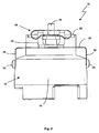
- An in Fig. 1 and 2 illustrated rotational angle measuring device 10 has a rotary encoder 12 with an encoder shaft 14.
- the encoder shaft 14 is rotatably connected to a shaft, not shown, of a drive system to be measured, so that the rotation of the encoder shaft 14 corresponds to the shaft of the drive system and the rotation of the shafts can thus be measured via the rotary encoder 12.
- a housing 16 of the rotary encoder 12 can not rotate. Therefore, the housing 16 is usually non-rotatably connected to a non-illustrated stationary part of the drive system to be measured.
- This rotationally fixed connection of the stationary parts of the rotary encoder 12 and the drive can be connected to one another via a stator coupling 18.
- the stator coupling has a torque arm 20 and a mounting plate 22.
- the torque arm 20 causes the actual rotation of the stators, so encoders housing 16 and stationary part of the drive system to be measured.
- the mounting plate 22 is merely for easy installation of the encoder 12 to the drive, as explained below in the description of the assembly process in detail.
- the torque arm 20 of the illustrated embodiment is in Fig. 3 shown separately. It consists of a one-piece punched and bent part 24, which has an annular base plate 26, from the edge of two first substantially diametrically arranged fastening tabs 28 and 30 protrude parallel extending in a first axial direction + R. With these first fastening tabs 28 and 30, the torque arm 20 on the housing 16 via fastening means, in particular screws 32 and 34, can be fixed. In the opposite axial direction -R protrude second fastening tabs 36 and 38, which are also arranged approximately diametrically and which serve the attachment of the torque arm 20 to the stator of the drive system to be measured.
- the torque arm 20 forms a spring parallelogram, which ensures an angle-faithful coupling of the rotary encoder 12 to the drive system to be measured in a special way.
- the torque arm 20 is preferably made of a resilient material high alternating strength, such as spring steel.
- the ends 40 and 42 of the second attachment tabs 36 and 38 are specially designed in accordance with the invention.
- the ends 40 and 42 are bent such that in each case a mounting plane 44 and 46 is formed, which lie approximately parallel to the base plate 26.
- end tabs 48 and 50 of the fastening tab 36 and end tabs 52 and 54 of the fastening tab 38 are bent over about 180 ° in such a way that a roughly oval-like shape is formed.
- At least the end tabs 48 and 50 and 52 and 54 are again parallel to the mounting plane 44 and 46 and are superimposed.
- the attachment planes 44 and 46 and the end tabs 48 and 50 and 52 and 54 have bores that are enforceable by attachment means, preferably attachment screws 56 and 58.
- the end tabs 48 and 50 or 52 and 54 are specially designed.
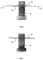
- the holes in the respective overlying end flaps 48 and 50 or 52 and 54 are not aligned exactly. Only pressure on the arches 60 and 62 or 64 and 66 of the ends 48 and 50 in the direction of the arrows 70 and 72 aligns the bores, so that a fastening screw 56 or 58 can be inserted easily, as in FIG Fig. 5 shown.
- the fixing screw 56 or 58 is inserted, the pressure is released.
- the end tabs 48 and 50 and 52 and 54 go again a piece apart and the mounting screw 56 or 58 is held jammed in the holes, as in Fig. 6 shown.
- stator coupling 18 The function of the stator coupling 18 is clear from the following step-by-step description of the installation of the rotational angular measurement direction 12.
- the stator coupling 14 is attached via the screws 32 and 34 to the rotary encoder 12, wherein the encoder shaft 14 is inserted positively with a hexagonal projection 73 in a recess 74 of the mounting plate 22.
- the mounting plate 22 is supported in the direction -R, the mounting plate 22 is held in position.
- the ends 40 and 42 thus form clamping elements for holding the mounting plate 22.
- the encoder housing 16, the encoder shaft 14 and the stator coupling 18 with its mounting plate 22 form a rotationally fixed unit, as in Fig. 1 is shown.
- the mounting screws 56 and 58 are also already in their in Fig. 1 and 2 shown position in the holes of the mounting tabs 36 and 38 inserted and held.
- the encoder shaft 14 is fixedly connected in a suitable manner with a drive shaft of the drive to be measured, for example screwed by the encoder housing 16 and thus the stator coupling 18 with mounting plate 22 ultimately the encoder shaft 14 is rotated. It may be advantageous that areas 76 of the encoder housing 16 also engage in a recess of the mounting plate 22, so that the encoder housing 16 directly and not only indirectly via the Torque support 20 against rotation of the mounting plate 22 is secured against rotation. Then, if necessary, a larger torque for tightening the encoder shaft 14 can be applied without the risk of bending the torque arm 20.
- the encoder shaft 14 After the encoder shaft 14 has been connected to the drive shaft, the already pre-assembled and held by the end tabs fastening screws 56 and 58 are tightened. As a result, the mounting plate 22 is moved in the direction of - R and ultimately lifted from the neck 73, whereby the encoder shaft 14 is released. The dimensions of the shafts are dimensioned such that when tightening the fasteners 56 and 58, the mounting plate 22 is completely lifted from the neck 73.
- the rotation angle measuring device 10 according to the invention is mounted and ready for operation.
Landscapes
- Physics & Mathematics (AREA)
- General Physics & Mathematics (AREA)
- Transmission And Conversion Of Sensor Element Output (AREA)
- Measurement Of Length, Angles, Or The Like Using Electric Or Magnetic Means (AREA)
- Length Measuring Devices With Unspecified Measuring Means (AREA)
- Body Structure For Vehicles (AREA)
Abstract
Description
Die Erfindung betrifft eine Drehwinkelmesseinrichtung gemäß dem Oberbegriff des Anspruch 1.The invention relates to a rotational angle measuring device according to the preamble of claim 1.
Eine derartige Drehwinkelmesseinrichtung ist aus der
Die Statorkupplung weist eine Drehmomentstütze auf, die die eigentliche Aufgabe der Verdrehsicherung hat. Diese besteht aus einer ringartigen Grundplatte, an der zwei Laschen zur Befestigung des Drehgebers und zwei Laschen zur Befestigung an der Antriebseinrichtung vorgesehen sind. Die Drehmomentstütze besteht aus Federstahl um radiale Scherbewegungen und insbesondere axiale Bewegungen, beispielsweise bei der Montage des Drehgebers an die Antriebseinrichtung, wie in der
Die Montage dieser Anordnungen gestaltet sich jedoch bei beschränktem Bauraum als schwierig, besonders dann, wenn das Gehäuse der Antriebseinrichtung (Stator) so geformt ist, dass dieses den Drehgeber umschließt und dieser nur durch eine axiale Öffnung montiert werden kann, deren Durchmesser wenig größer ist, als der des Drehgebers. Die Statorkupplung Encoderwelle, lässt sich noch, insbesondere dank der in der
Die Erfindung löst diese Aufgabe, indem eine neue Drehwinkelmesseinrichtung geschaffen ist, deren Drehmomentstütze Haltemittel aufweist zum Halten von Befestigungsmitteln, die in der Regel aus Schrauben bestehen. Damit ist die Montage des Drehgebers an die Antriebseinheit erheblich vereinfacht und kann entsprechend schnell und problemlos erfolgen. Dies gilt umso mehr je kleiner der Drehgeber und damit die Befestigungsschrauben sind. Die Befestigungsschrauben können nicht mehr verloren gehen. Ein Verlieren könnte unter Umständen größere Montagezeiten oder Maschinenstillstandszeiten verursachen, was durch die Erfindung sicher vermieden werden kann.The invention achieves this object by providing a new angle of rotation measuring device whose torque support has holding means for holding fastening means, which as a rule consist of screws. Thus, the assembly of the encoder to the drive unit is considerably simplified and can be done quickly and easily. This is all the more the smaller the encoder and thus the mounting screws are. The fixing screws can not be lost anymore. Losing could possibly cause larger assembly times or machine downtime, which can be safely avoided by the invention.
Da die Montage mit der Erfindung vereinfacht ist und die Befestigungsschrauben nicht von Hand eingeführt werden müssen, kann die erfindungsgemäße Drehwinkelmesseinrichtung in kleinere Bauräume montiert werden. Insbesondere für Drehgeber mit kleinen geometrischen Abmessungen, für deren Einbau meist nur ein beschränkter Bauraum zur Verfügung steht, ist diese Konstruktion daher vorteilhaft. Die Befestigungsmittel müssen lediglich mit einem geeigneten Werkzeug, beispielsweise einem Schraubendreher, zugänglich sein.Since the assembly is simplified with the invention and the fastening screws do not need to be inserted by hand, the rotation angle measuring device according to the invention can be mounted in smaller spaces. In particular, for rotary encoders with small geometric dimensions, for their installation usually only a limited space is available, this construction is therefore advantageous. The fasteners need only be accessible with a suitable tool, such as a screwdriver.
Die Haltemittel sind integraler Bestandteil der Befestigungslaschen, indem sie jeweils gebildet sind durch zwei Klemmlaschen, die Endstücke der Befestigungslaschen sind und das Befestigungsmittel festklemmen.The retaining means are an integral part of the fastening tabs, in that they are each formed by two clamping tabs which are end pieces of the fastening tabs and clamp the fastening means.
In konstruktiv einfacher Weise sind die Klemmlaschen gebildet durch zwei übereinanderliegende Laschen, die jeweils eine Bohrung zur Aufnahme des Befestigungsmittels aufweisen, wobei im entspannten Zustand der Klemmlaschen die Bohrungen leicht parallel versetzt sind, so dass ein die Bohrungen durchsetzendes Befestigungsmittel im entspannten Zustand eingeklemmt gehalten wird.In a structurally simple manner, the clamping tabs are formed by two superimposed tabs, each having a bore for receiving the fastener, wherein the holes are slightly offset parallel in the relaxed state of the clamping straps, so that the holes passing through fastener is held clamped in the relaxed state.
Bevorzugt sind die Klemmlaschen zu einem eine etwa ovalartige Form aufweisenden Ende der jeweiligen zweiten Befestigungslasche gebogen. Dadurch können die zweiten Befestigungslaschen, wenn die Drehmomentstütze aus einem federelastischen Material, beispielsweise Federstahl, besteht, federnd ausgebildet werden, wobei sich die Federkraft durch Zusammendrücken der Ovalform ergibt.The clamping straps are preferably bent to form an approximately oval-shaped end of the respective second fastening strap. As a result, when the torque arm is made of a resilient material such as spring steel, the second mounting tabs can be resiliently formed, with the spring force resulting from compression of the oval shape.
Dies ist besonders vorteilhaft, wenn die Statorkupplung eine Montageplatte zur Montage der Statorkupplung an den stationären Teil des Antriebs aufweist, so dass die Montageplatte, wie an sich aus dem Stand der Technik (
Die Befestigungslaschen der Drehmomentstütze der erfindungsgemäßen Drehwinkelmesseinrichtung weisen somit Haltemittel zum Halten von Befestigungsmitteln auf, die integraler Bestandteil der Befestigungslasche sind und gleichzeitig eine Form aufweisen (oval), die eine federnde Befestigung erlaubt.The fastening tabs of the torque arm of the rotation angle measuring device according to the invention thus have holding means for holding fastening means, which are an integral part of the fastening tab and at the same time have a shape (oval), which allows a resilient attachment.
Im Nachfolgenden wird die Erfindung anhand eines Ausführungsbeispiels unter Bezugnahme auf die Zeichnungen im Einzelnen erläutert. In der Zeichnung zeigen:
- Fig. 1
- Eine erfindungsgemäße Drehwinkelmesseinrichtung;
- Fig. 2
- die Drehwinkelmesseinrichtung aus
Fig. 1 ohne Encoderwelle von einer Seite gesehen; - Fig. 3 und 4
- Ansichten einer Statorkupplung der Drehwinkelmesseinrichtung aus
Fig. 1 ; - Fig. 5 und 6
- Detailansichten der Halterung eines Befestigungsmittels.
- Fig. 1
- A rotation angle measuring device according to the invention;
- Fig. 2
- the rotational angle measuring device
Fig. 1 without encoder shaft from one Side view; - 3 and 4
- Views of a stator coupling of the rotation angle measuring device
Fig. 1 ; - FIGS. 5 and 6
- Detail views of the holder of a fastener.
Eine in
Diese drehfeste Verbindung der stationären Teile des Drehgebers 12 und des Antriebs sind über eine Statorkupplung 18 miteinander verbindbar. Die Statorkupplung weist eine Drehmomentstütze 20 und eine Montageplatte 22 auf. Die Drehmomentstütze 20 bewirkt die eigentliche Verdrehsicherung der Statoren, also Drehgebergehäuse 16 und stationärer Teil des zu messenden Antriebssystems. Die Montageplatte 22 dient lediglich der einfachen Montage des Drehgebers 12 an den Antrieb, wie weiter unten bei der Beschreibung des Montageprozesses im Einzelnen erläutert.This rotationally fixed connection of the stationary parts of the
Die Drehmomentstütze 20 des dargestellten Ausführungsbeispiels ist in
Die Enden 40 und 42 der zweiten Befestigungslaschen 36 und 38 sind speziell entsprechend der Erfindung ausgebildet. Zunächst sind die Enden 40 und 42 derart abgebogen, dass jeweils eine Befestigungsebene 44 und 46 entsteht, die in etwa parallel zur Grundplatte 26 liegen. Wie besonders deutlich in der Seitenansicht der
Damit die zweiten Befestigungslaschen 36 und 38 an dem Stator des Antriebs befestigt werden können, weisen die Befestigungsebenen 44 und 46 sowie die Endlaschen 48 und 50 bzw. 52 und 54 Bohrungen auf, die von Befestigungsmitteln, bevorzugt Befestigungsschrauben 56 und 58, durchsetzbar sind.In order for the
Damit die Befestigungsschrauben 56 und 58 nicht während der Montage aus den Bohrungen fallen können, sind die Endlaschen 48 und 50 bzw. 52 und 54 speziell ausgebildet. Im entspannten Zustand der Enden 40 und 42 fluchten die Bohrungen in den jeweils übereinanderliegenden Endlaschen 48 und 50 bzw. 52 und 54 nicht exakt. Erst Druck auf die Bögen 60 und 62 bzw. 64 und 66 der Enden 48 und 50 in Richtung der Pfeile 70 und 72 bringt die Bohrungen in eine Flucht, so dass problemlos eine Befestigungsschraube 56 oder 58 eingeführt werden kann, wie in
Die Funktion der Statorkupplung 18 wird aus der folgenden schrittweisen Beschreibung der Montage der Drehwinkelmessenrichtung 12 deutlich.The function of the
Zunächst ist die Statorkupplung 14 über die Schrauben 32 und 34 an dem Drehgeber 12 befestigt, wobei die Encoderwelle 14 mit einem sechseckigen Ansatz 73 in einer Aussparung 74 der Montageplatte 22 formschlüssig eingesetzt ist. Über die federelastischen Enden 40 und 42, an deren Endlaschen 48 und 50 bzw. 52 und 54 sich die Montageplatte 22 in Richtung -R abstützt, ist die Montageplatte 22 in ihrer Position gehalten. Die Enden 40 und 42 bilden somit Spannelemente zum Halten der Montageplatte 22. Das Drehgebergehäuse 16, die Encoderwelle 14 und die Statorkupplung 18 mit ihrer Montageplatte 22 bilden eine verdrehfeste Einheit, wie sie in
Dann wird die Encoderwelle 14 in geeigneter Weise mit einer Antriebswelle des zu messenden Antriebs fest verbunden, z.B. verschraubt, indem das Drehgebergehäuse 16 und damit über die Statorkupplung 18 mit Montageplatte 22 letztlich die Encoderwelle 14 gedreht wird. Es kann vorteilhaft sein, dass Bereiche 76 des Drehgebergehäuses 16 ebenfalls in eine Aussparung der Montageplatte 22 eingreifen, so dass das Drehgebergehäuse 16 direkt und nicht nur indirekt über die Drehmomentstütze 20 gegenüber der Montageplatte 22 verdrehgesichert ist. Dann kann gegebenenfalls ein größeres Drehmoment zum Festziehen der Encoderwelle 14 aufgebracht werden ohne dass die Gefahr besteht, die Drehmomentstütze 20 zu verbiegen.Then, the
Nachdem die Encoderwelle 14 mit der Antriebswelle verbunden wurde, werden die schon vormontierten und durch die Endlaschen festgehaltenen Befestigungsschrauben 56 und 58 angezogen. Dadurch wird die Montageplatte 22 in Richtung - R bewegt und letztlich von dem Ansatz 73 abgehoben, wodurch die Encoderwelle 14 freigegeben ist. Die Abmessungen der Wellen sind derart bemessen, dass beim Anziehen der Befestigungselemente 56 und 58 die Montageplatte 22 vollständig von dem Ansatz 73 abgehoben wird. Die erfindungsgemäße Drehwinkelmesseinrichtung 10 ist montiert und betriebsbereit.After the
Claims (6)
- Rotation angle measurement device for measurement of angle-dependent measurement variables, having a rotary encoder (12) with an encoder shaft (14) which is mounted in a rotary encoder housing (16), having a stator coupling (18), which has a torque support (20), for rotationally fixed connection of the rotary encoder housing (16) to a stationary part of a drive system to be measured, with the torque support (20) having at least two first attachment lugs (28, 30) for attachment of the torque support (20) to the rotary encoder housing (16), and having at least two second attachment lugs (36, 38) for attachment of the torque support (20) to the stationary part, characterized in that the second attachment lugs (36, 38) have holding means (48, 50; 52, 54) for holding attachment means (56, 58), whereby the holding means (48, 50; 52, 54) are each formed by two clamping lugs (48, 50; 52, 54) whereby the clamping lugs (48, 50; 52, 54) are formed by two end lugs (48, 50; 52, 54) which are located one above the other, each have a hole for holding the attachment means (56, 58), with the holes being offset slightly parallel in the unstressed state of the clamping lugs (48, 50; 52, 54).
- Rotation angle measurement device according to Claim 1, characterized in that the end lugs (48, 50; 52, 54) are curved to form an end, which has a roughly oval shape, of the respective second attachment lug (36, 38).
- Rotation angle measurement device according to one of the preceding claims, characterized in that the stator coupling (18) has a mounting plate (22) for mounting the stator coupling (18) on the stationary part of the drive.
- Rotation angle measurement device according to Claim 3, characterized in that the torque support (20) has at least one tensioning element which, when the rotary encoder (12) is not in the installed state, firmly holds the mounting plate (22) on the rotary encoder (12), and can be deformed against its tensioning force in order to mount the rotary encoder (12) on the stationary part of the drive.
- Rotation angle measurement device according to Claim 4, characterized in that the tensioning element is formed by those ends (40, 42) of the second attachment lugs (36, 38) which have the oval shape and whose stress is produced by compression of the oval shape by the attachment means (56, 58).
- Rotation angle measurement device according to one of the preceding claims, characterized in that the torque support is composed of a resiliently elastic material, for example spring steel.
Applications Claiming Priority (2)
| Application Number | Priority Date | Filing Date | Title |
|---|---|---|---|
| DE202004001066U DE202004001066U1 (en) | 2004-01-23 | 2004-01-23 | Rotation angle measurement device |
| DE202004001066U | 2004-01-23 |
Publications (3)
| Publication Number | Publication Date |
|---|---|
| EP1557643A1 EP1557643A1 (en) | 2005-07-27 |
| EP1557643B1 EP1557643B1 (en) | 2006-06-07 |
| EP1557643B2 true EP1557643B2 (en) | 2013-04-24 |
Family
ID=32240780
Family Applications (1)
| Application Number | Title | Priority Date | Filing Date |
|---|---|---|---|
| EP05000439.9A Expired - Lifetime EP1557643B2 (en) | 2004-01-23 | 2005-01-12 | Angle detector |
Country Status (3)
| Country | Link |
|---|---|
| EP (1) | EP1557643B2 (en) |
| AT (1) | ATE329232T1 (en) |
| DE (2) | DE202004001066U1 (en) |
Cited By (1)
| Publication number | Priority date | Publication date | Assignee | Title |
|---|---|---|---|---|
| DE102024129918B3 (en) | 2024-10-15 | 2026-03-12 | Baumer Germany Gmbh & Co. Kg | Torque support for a rotary encoder and such a rotary encoder |
Families Citing this family (5)
| Publication number | Priority date | Publication date | Assignee | Title |
|---|---|---|---|---|
| DE102006038981B4 (en) * | 2006-08-21 | 2010-09-30 | Lenord, Bauer & Co.Gmbh | stator |
| EP2693170B1 (en) * | 2012-07-31 | 2014-09-24 | SICK STEGMANN GmbH | Stator coupling |
| DE102012023679C5 (en) * | 2012-11-26 | 2016-11-17 | Fritz Kübler GmbH Zähl- und Sensortechnik | Position securing element, rotary encoder system with a position securing element and method for fastening a rotary encoder system |
| CN114234795B (en) * | 2021-12-17 | 2024-02-13 | 上海易咖智车科技有限公司 | Transport vechicle corner mechanical range detection device |
| CN115164015A (en) * | 2022-07-11 | 2022-10-11 | 徐州徐工矿业机械有限公司 | Engineering machine tool rotary platform gyration angle monitoring devices |
Citations (2)
| Publication number | Priority date | Publication date | Assignee | Title |
|---|---|---|---|---|
| JP2000046244A (en) † | 1998-07-29 | 2000-02-18 | Nichiei Intekku Kk | Piping band device |
| EP1225428A2 (en) † | 2001-01-23 | 2002-07-24 | Dr. Johannes Heidenhain GmbH | Angle measuring system |
Family Cites Families (3)
| Publication number | Priority date | Publication date | Assignee | Title |
|---|---|---|---|---|
| US5018397A (en) * | 1990-01-26 | 1991-05-28 | The Boeing Company | Transducer input shaft lock mechanism |
| DE19629585C2 (en) * | 1995-09-06 | 1998-12-10 | Heidenhain Gmbh Dr Johannes | Angle measuring device |
| DE10216376B4 (en) * | 2002-04-12 | 2005-08-25 | Sick Stegmann Gmbh | Rotation angle measuring system |
-
2004
- 2004-01-23 DE DE202004001066U patent/DE202004001066U1/en not_active Expired - Lifetime
-
2005
- 2005-01-12 DE DE502005000016T patent/DE502005000016D1/en not_active Expired - Lifetime
- 2005-01-12 AT AT05000439T patent/ATE329232T1/en not_active IP Right Cessation
- 2005-01-12 EP EP05000439.9A patent/EP1557643B2/en not_active Expired - Lifetime
Patent Citations (2)
| Publication number | Priority date | Publication date | Assignee | Title |
|---|---|---|---|---|
| JP2000046244A (en) † | 1998-07-29 | 2000-02-18 | Nichiei Intekku Kk | Piping band device |
| EP1225428A2 (en) † | 2001-01-23 | 2002-07-24 | Dr. Johannes Heidenhain GmbH | Angle measuring system |
Cited By (1)
| Publication number | Priority date | Publication date | Assignee | Title |
|---|---|---|---|---|
| DE102024129918B3 (en) | 2024-10-15 | 2026-03-12 | Baumer Germany Gmbh & Co. Kg | Torque support for a rotary encoder and such a rotary encoder |
Also Published As
| Publication number | Publication date |
|---|---|
| DE502005000016D1 (en) | 2006-07-20 |
| EP1557643A1 (en) | 2005-07-27 |
| DE202004001066U1 (en) | 2004-04-29 |
| EP1557643B1 (en) | 2006-06-07 |
| ATE329232T1 (en) | 2006-06-15 |
Similar Documents
| Publication | Publication Date | Title |
|---|---|---|
| EP1353150B1 (en) | Angle detector | |
| DE2460961C3 (en) | Device for applying a pretensioning force to a screw bolt with a nut | |
| DE19629585C2 (en) | Angle measuring device | |
| EP0520164A1 (en) | Threaded joint | |
| EP2331913B1 (en) | Device for the clamping attachment of a scale | |
| EP3308066B1 (en) | Clamp having a clamp band and a pre-positioner | |
| WO2004020844A1 (en) | Fixing arrangement | |
| EP3286440B2 (en) | Device for securing to a component | |
| EP1527660B1 (en) | Torsional fixing device, especially for the housing of a measuring transducer | |
| AT974U1 (en) | CONNECTING ARRANGEMENT | |
| DE102009028517A1 (en) | Mounting arrangement of planetary pin | |
| EP1557643B2 (en) | Angle detector | |
| DE10063013A1 (en) | Angle measuring device has screw radially screwed into stationary object for clamping mounting piece via expansion piece | |
| WO2001065634A1 (en) | Device for fixing a vehicle antenna | |
| DE2621037A1 (en) | STORAGE EQUIPMENT FOR A CYLINDER-SHAPED MAGNETIC SENSOR | |
| DE102011083358B4 (en) | Clamping device, in particular for a roof rack of a motor vehicle | |
| DE102005059247B4 (en) | braking device | |
| DE102008021162A1 (en) | Holder for a pedal force servo on a vehicle structure | |
| WO1999016648A1 (en) | Wiper system | |
| DE10026958A1 (en) | Stator coupling is formed in one piece out of spring material and has middle region with outer and inner leaf spring arms | |
| DE102019008731A1 (en) | Screw arrangement | |
| DE102021114125B3 (en) | Assembly tool for assembling a camshaft adjuster and kit with this assembly tool | |
| EP1643217B1 (en) | Scanning unit and position measuring arrangement | |
| EP2412989B1 (en) | Torque limiting element for screws | |
| EP4043740A1 (en) | Finger spring washer |
Legal Events
| Date | Code | Title | Description |
|---|---|---|---|
| PUAI | Public reference made under article 153(3) epc to a published international application that has entered the european phase |
Free format text: ORIGINAL CODE: 0009012 |
|
| AK | Designated contracting states |
Kind code of ref document: A1 Designated state(s): AT BE BG CH CY CZ DE DK EE ES FI FR GB GR HU IE IS IT LI LT LU MC NL PL PT RO SE SI SK TR |
|
| AX | Request for extension of the european patent |
Extension state: AL BA HR LV MK YU |
|
| 17P | Request for examination filed |
Effective date: 20051012 |
|
| GRAP | Despatch of communication of intention to grant a patent |
Free format text: ORIGINAL CODE: EPIDOSNIGR1 |
|
| AKX | Designation fees paid |
Designated state(s): AT BE BG CH CY CZ DE DK EE ES FI FR GB GR HU IE IS IT LI LT LU MC NL PL PT RO SE SI SK TR |
|
| GRAS | Grant fee paid |
Free format text: ORIGINAL CODE: EPIDOSNIGR3 |
|
| GRAA | (expected) grant |
Free format text: ORIGINAL CODE: 0009210 |
|
| AK | Designated contracting states |
Kind code of ref document: B1 Designated state(s): AT BE BG CH CY CZ DE DK EE ES FI FR GB GR HU IE IS IT LI LT LU MC NL PL PT RO SE SI SK TR |
|
| PG25 | Lapsed in a contracting state [announced via postgrant information from national office to epo] |
Ref country code: IT Free format text: LAPSE BECAUSE OF FAILURE TO SUBMIT A TRANSLATION OF THE DESCRIPTION OR TO PAY THE FEE WITHIN THE PRESCRIBED TIME-LIMIT;WARNING: LAPSES OF ITALIAN PATENTS WITH EFFECTIVE DATE BEFORE 2007 MAY HAVE OCCURRED AT ANY TIME BEFORE 2007. THE CORRECT EFFECTIVE DATE MAY BE DIFFERENT FROM THE ONE RECORDED. Effective date: 20060607 Ref country code: CZ Free format text: LAPSE BECAUSE OF FAILURE TO SUBMIT A TRANSLATION OF THE DESCRIPTION OR TO PAY THE FEE WITHIN THE PRESCRIBED TIME-LIMIT Effective date: 20060607 Ref country code: IE Free format text: LAPSE BECAUSE OF FAILURE TO SUBMIT A TRANSLATION OF THE DESCRIPTION OR TO PAY THE FEE WITHIN THE PRESCRIBED TIME-LIMIT Effective date: 20060607 Ref country code: LT Free format text: LAPSE BECAUSE OF FAILURE TO SUBMIT A TRANSLATION OF THE DESCRIPTION OR TO PAY THE FEE WITHIN THE PRESCRIBED TIME-LIMIT Effective date: 20060607 Ref country code: RO Free format text: LAPSE BECAUSE OF FAILURE TO SUBMIT A TRANSLATION OF THE DESCRIPTION OR TO PAY THE FEE WITHIN THE PRESCRIBED TIME-LIMIT Effective date: 20060607 Ref country code: PL Free format text: LAPSE BECAUSE OF FAILURE TO SUBMIT A TRANSLATION OF THE DESCRIPTION OR TO PAY THE FEE WITHIN THE PRESCRIBED TIME-LIMIT Effective date: 20060607 Ref country code: SK Free format text: LAPSE BECAUSE OF FAILURE TO SUBMIT A TRANSLATION OF THE DESCRIPTION OR TO PAY THE FEE WITHIN THE PRESCRIBED TIME-LIMIT Effective date: 20060607 Ref country code: FI Free format text: LAPSE BECAUSE OF FAILURE TO SUBMIT A TRANSLATION OF THE DESCRIPTION OR TO PAY THE FEE WITHIN THE PRESCRIBED TIME-LIMIT Effective date: 20060607 Ref country code: NL Free format text: LAPSE BECAUSE OF FAILURE TO SUBMIT A TRANSLATION OF THE DESCRIPTION OR TO PAY THE FEE WITHIN THE PRESCRIBED TIME-LIMIT Effective date: 20060607 Ref country code: SI Free format text: LAPSE BECAUSE OF FAILURE TO SUBMIT A TRANSLATION OF THE DESCRIPTION OR TO PAY THE FEE WITHIN THE PRESCRIBED TIME-LIMIT Effective date: 20060607 |
|
| REG | Reference to a national code |
Ref country code: GB Ref legal event code: FG4D Free format text: NOT ENGLISH |
|
| REG | Reference to a national code |
Ref country code: CH Ref legal event code: EP |
|
| GBT | Gb: translation of ep patent filed (gb section 77(6)(a)/1977) |
Effective date: 20060607 |
|
| REG | Reference to a national code |
Ref country code: IE Ref legal event code: FG4D Free format text: LANGUAGE OF EP DOCUMENT: GERMAN |
|
| REF | Corresponds to: |
Ref document number: 502005000016 Country of ref document: DE Date of ref document: 20060720 Kind code of ref document: P |
|
| PG25 | Lapsed in a contracting state [announced via postgrant information from national office to epo] |
Ref country code: DK Free format text: LAPSE BECAUSE OF FAILURE TO SUBMIT A TRANSLATION OF THE DESCRIPTION OR TO PAY THE FEE WITHIN THE PRESCRIBED TIME-LIMIT Effective date: 20060907 Ref country code: SE Free format text: LAPSE BECAUSE OF FAILURE TO SUBMIT A TRANSLATION OF THE DESCRIPTION OR TO PAY THE FEE WITHIN THE PRESCRIBED TIME-LIMIT Effective date: 20060907 |
|
| PG25 | Lapsed in a contracting state [announced via postgrant information from national office to epo] |
Ref country code: ES Free format text: LAPSE BECAUSE OF FAILURE TO SUBMIT A TRANSLATION OF THE DESCRIPTION OR TO PAY THE FEE WITHIN THE PRESCRIBED TIME-LIMIT Effective date: 20060918 |
|
| PG25 | Lapsed in a contracting state [announced via postgrant information from national office to epo] |
Ref country code: PT Free format text: LAPSE BECAUSE OF FAILURE TO SUBMIT A TRANSLATION OF THE DESCRIPTION OR TO PAY THE FEE WITHIN THE PRESCRIBED TIME-LIMIT Effective date: 20061107 |
|
| NLV1 | Nl: lapsed or annulled due to failure to fulfill the requirements of art. 29p and 29m of the patents act | ||
| REG | Reference to a national code |
Ref country code: IE Ref legal event code: FD4D |
|
| PG25 | Lapsed in a contracting state [announced via postgrant information from national office to epo] |
Ref country code: MC Free format text: LAPSE BECAUSE OF NON-PAYMENT OF DUE FEES Effective date: 20070131 |
|
| PLBI | Opposition filed |
Free format text: ORIGINAL CODE: 0009260 |
|
| 26 | Opposition filed |
Opponent name: DR. JOHANNES HEIDENHAIN GMBH Effective date: 20070220 |
|
| PLAX | Notice of opposition and request to file observation + time limit sent |
Free format text: ORIGINAL CODE: EPIDOSNOBS2 |
|
| EN | Fr: translation not filed | ||
| PLBB | Reply of patent proprietor to notice(s) of opposition received |
Free format text: ORIGINAL CODE: EPIDOSNOBS3 |
|
| BERE | Be: lapsed |
Owner name: SICK STEGMANN G.M.B.H. Effective date: 20070131 |
|
| PG25 | Lapsed in a contracting state [announced via postgrant information from national office to epo] |
Ref country code: BE Free format text: LAPSE BECAUSE OF NON-PAYMENT OF DUE FEES Effective date: 20070131 |
|
| PG25 | Lapsed in a contracting state [announced via postgrant information from national office to epo] |
Ref country code: GR Free format text: LAPSE BECAUSE OF FAILURE TO SUBMIT A TRANSLATION OF THE DESCRIPTION OR TO PAY THE FEE WITHIN THE PRESCRIBED TIME-LIMIT Effective date: 20060908 Ref country code: FR Free format text: LAPSE BECAUSE OF FAILURE TO SUBMIT A TRANSLATION OF THE DESCRIPTION OR TO PAY THE FEE WITHIN THE PRESCRIBED TIME-LIMIT Effective date: 20070309 |
|
| PG25 | Lapsed in a contracting state [announced via postgrant information from national office to epo] |
Ref country code: BG Free format text: LAPSE BECAUSE OF FAILURE TO SUBMIT A TRANSLATION OF THE DESCRIPTION OR TO PAY THE FEE WITHIN THE PRESCRIBED TIME-LIMIT Effective date: 20060907 Ref country code: AT Free format text: LAPSE BECAUSE OF NON-PAYMENT OF DUE FEES Effective date: 20070112 |
|
| PG25 | Lapsed in a contracting state [announced via postgrant information from national office to epo] |
Ref country code: EE Free format text: LAPSE BECAUSE OF FAILURE TO SUBMIT A TRANSLATION OF THE DESCRIPTION OR TO PAY THE FEE WITHIN THE PRESCRIBED TIME-LIMIT Effective date: 20060607 |
|
| PG25 | Lapsed in a contracting state [announced via postgrant information from national office to epo] |
Ref country code: FR Free format text: LAPSE BECAUSE OF FAILURE TO SUBMIT A TRANSLATION OF THE DESCRIPTION OR TO PAY THE FEE WITHIN THE PRESCRIBED TIME-LIMIT Effective date: 20060607 |
|
| PG25 | Lapsed in a contracting state [announced via postgrant information from national office to epo] |
Ref country code: IS Free format text: LAPSE BECAUSE OF NON-PAYMENT OF DUE FEES Effective date: 20070131 |
|
| PGRI | Patent reinstated in contracting state [announced from national office to epo] |
Ref country code: IT Effective date: 20090301 |
|
| PG25 | Lapsed in a contracting state [announced via postgrant information from national office to epo] |
Ref country code: CY Free format text: LAPSE BECAUSE OF FAILURE TO SUBMIT A TRANSLATION OF THE DESCRIPTION OR TO PAY THE FEE WITHIN THE PRESCRIBED TIME-LIMIT Effective date: 20060607 Ref country code: LU Free format text: LAPSE BECAUSE OF NON-PAYMENT OF DUE FEES Effective date: 20070112 |
|
| REG | Reference to a national code |
Ref country code: CH Ref legal event code: PL |
|
| PG25 | Lapsed in a contracting state [announced via postgrant information from national office to epo] |
Ref country code: HU Free format text: LAPSE BECAUSE OF FAILURE TO SUBMIT A TRANSLATION OF THE DESCRIPTION OR TO PAY THE FEE WITHIN THE PRESCRIBED TIME-LIMIT Effective date: 20061208 Ref country code: TR Free format text: LAPSE BECAUSE OF FAILURE TO SUBMIT A TRANSLATION OF THE DESCRIPTION OR TO PAY THE FEE WITHIN THE PRESCRIBED TIME-LIMIT Effective date: 20060607 |
|
| PG25 | Lapsed in a contracting state [announced via postgrant information from national office to epo] |
Ref country code: LI Free format text: LAPSE BECAUSE OF NON-PAYMENT OF DUE FEES Effective date: 20090131 Ref country code: CH Free format text: LAPSE BECAUSE OF NON-PAYMENT OF DUE FEES Effective date: 20090131 |
|
| PUAH | Patent maintained in amended form |
Free format text: ORIGINAL CODE: 0009272 |
|
| STAA | Information on the status of an ep patent application or granted ep patent |
Free format text: STATUS: PATENT MAINTAINED AS AMENDED |
|
| 27A | Patent maintained in amended form |
Effective date: 20130424 |
|
| AK | Designated contracting states |
Kind code of ref document: B2 Designated state(s): AT BE BG CH CY CZ DE DK EE ES FI FR GB GR HU IE IS IT LI LT LU MC NL PL PT RO SE SI SK TR |
|
| PGFP | Annual fee paid to national office [announced via postgrant information from national office to epo] |
Ref country code: GB Payment date: 20130122 Year of fee payment: 9 |
|
| REG | Reference to a national code |
Ref country code: DE Ref legal event code: R102 Ref document number: 502005000016 Country of ref document: DE Effective date: 20130424 |
|
| GBPC | Gb: european patent ceased through non-payment of renewal fee |
Effective date: 20140112 |
|
| PG25 | Lapsed in a contracting state [announced via postgrant information from national office to epo] |
Ref country code: GB Free format text: LAPSE BECAUSE OF NON-PAYMENT OF DUE FEES Effective date: 20140112 |
|
| REG | Reference to a national code |
Ref country code: DE Ref legal event code: R082 Ref document number: 502005000016 Country of ref document: DE Ref country code: DE Ref legal event code: R081 Ref document number: 502005000016 Country of ref document: DE Owner name: SICK AG, DE Free format text: FORMER OWNER: SICK STEGMANN GMBH, 78166 DONAUESCHINGEN, DE |
|
| PGFP | Annual fee paid to national office [announced via postgrant information from national office to epo] |
Ref country code: IT Payment date: 20230131 Year of fee payment: 19 |
|
| PGFP | Annual fee paid to national office [announced via postgrant information from national office to epo] |
Ref country code: DE Payment date: 20240119 Year of fee payment: 20 |
|
| REG | Reference to a national code |
Ref country code: DE Ref legal event code: R071 Ref document number: 502005000016 Country of ref document: DE |
|
| PG25 | Lapsed in a contracting state [announced via postgrant information from national office to epo] |
Ref country code: IT Free format text: LAPSE BECAUSE OF NON-PAYMENT OF DUE FEES Effective date: 20240112 |