EP1557495B1 - A compactor - Google Patents
A compactor Download PDFInfo
- Publication number
- EP1557495B1 EP1557495B1 EP05250279A EP05250279A EP1557495B1 EP 1557495 B1 EP1557495 B1 EP 1557495B1 EP 05250279 A EP05250279 A EP 05250279A EP 05250279 A EP05250279 A EP 05250279A EP 1557495 B1 EP1557495 B1 EP 1557495B1
- Authority
- EP
- European Patent Office
- Prior art keywords
- handle
- support member
- coupled
- compactor according
- compactor
- Prior art date
- Legal status (The legal status is an assumption and is not a legal conclusion. Google has not performed a legal analysis and makes no representation as to the accuracy of the status listed.)
- Expired - Lifetime
Links
- 239000013536 elastomeric material Substances 0.000 claims description 2
- 230000001419 dependent effect Effects 0.000 claims 2
- 230000000712 assembly Effects 0.000 description 13
- 238000000429 assembly Methods 0.000 description 13
- 241001247986 Calotropis procera Species 0.000 description 8
- 239000000463 material Substances 0.000 description 8
- 238000005056 compaction Methods 0.000 description 3
- 239000010426 asphalt Substances 0.000 description 2
- 230000008878 coupling Effects 0.000 description 2
- 238000010168 coupling process Methods 0.000 description 2
- 238000005859 coupling reaction Methods 0.000 description 2
- 239000008187 granular material Substances 0.000 description 2
- -1 gravel Substances 0.000 description 2
- 239000004576 sand Substances 0.000 description 2
- 239000002689 soil Substances 0.000 description 2
- 241001654170 Caladenia catenata Species 0.000 description 1
- 239000006096 absorbing agent Substances 0.000 description 1
- 239000000872 buffer Substances 0.000 description 1
- 238000010276 construction Methods 0.000 description 1
- 238000013016 damping Methods 0.000 description 1
- 238000009434 installation Methods 0.000 description 1
- 239000012528 membrane Substances 0.000 description 1
- 230000035939 shock Effects 0.000 description 1
- 238000003466 welding Methods 0.000 description 1
Images





Classifications
-
- B—PERFORMING OPERATIONS; TRANSPORTING
- B25—HAND TOOLS; PORTABLE POWER-DRIVEN TOOLS; MANIPULATORS
- B25D—PERCUSSIVE TOOLS
- B25D17/00—Details of, or accessories for, portable power-driven percussive tools
- B25D17/04—Handles; Handle mountings
- B25D17/043—Handles resiliently mounted relative to the hammer housing
-
- E—FIXED CONSTRUCTIONS
- E01—CONSTRUCTION OF ROADS, RAILWAYS, OR BRIDGES
- E01C—CONSTRUCTION OF, OR SURFACES FOR, ROADS, SPORTS GROUNDS, OR THE LIKE; MACHINES OR AUXILIARY TOOLS FOR CONSTRUCTION OR REPAIR
- E01C19/00—Machines, tools or auxiliary devices for preparing or distributing paving materials, for working the placed materials, or for forming, consolidating, or finishing the paving
- E01C19/22—Machines, tools or auxiliary devices for preparing or distributing paving materials, for working the placed materials, or for forming, consolidating, or finishing the paving for consolidating or finishing laid-down unset materials
- E01C19/30—Tamping or vibrating apparatus other than rollers ; Devices for ramming individual paving elements
- E01C19/34—Power-driven rammers or tampers, e.g. air-hammer impacted shoes for ramming stone-sett paving; Hand-actuated ramming or tamping machines, e.g. tampers with manually hoisted dropping weight
- E01C19/38—Power-driven rammers or tampers, e.g. air-hammer impacted shoes for ramming stone-sett paving; Hand-actuated ramming or tamping machines, e.g. tampers with manually hoisted dropping weight with means specifically for generating vibrations, e.g. vibrating plate compactors, immersion vibrators
-
- E—FIXED CONSTRUCTIONS
- E02—HYDRAULIC ENGINEERING; FOUNDATIONS; SOIL SHIFTING
- E02D—FOUNDATIONS; EXCAVATIONS; EMBANKMENTS; UNDERGROUND OR UNDERWATER STRUCTURES
- E02D3/00—Improving or preserving soil or rock, e.g. preserving permafrost soil
- E02D3/02—Improving by compacting
- E02D3/046—Improving by compacting by tamping or vibrating, e.g. with auxiliary watering of the soil
- E02D3/074—Vibrating apparatus operating with systems involving rotary unbalanced masses
Definitions
- the invention relates to a compactor and especially, a ground compactor for compaction of granular materials, such as gravel, soil, sand, hardcore materials and other aggregates, and/or paving materials such as paving block, paving slabs, flagstones and asphalt.
- granular materials such as gravel, soil, sand, hardcore materials and other aggregates
- paving materials such as paving block, paving slabs, flagstones and asphalt.
- Conventional plate compactors use a motor, such as a petrol or diesel engine to vibrate a base plate below the motor.
- the base plate is generally weighted to increase the compaction of the material to be compacted.
- the compactor includes a handle which is held by an operator to control the movement of the compactor across the material being compacted. Hence, the handle is also subject to the vibration generated by the compactor.
- VWF vibration induced white finger
- patent document US-4 113 403 is a compactor provided with shock absorbers for reducing vibration of the handle and fatigue of the operator.
- EP 1 127 983 is a compactor being provided with a vibration damped bracket handle. In addition to rubber buffers connected at the free ends of the handle, it is also provided with a damping mass extending between the two ends of the handle.
- the object of the invention is to reduce the vibration of the handle of a compactor.
- a compactor comprising a support member, a base plate mounted for vibration on the support member, a motor mounted on the support member, the output of the motor being coupled to the base plate to cause in use, vibration of the base plate,, a handle and a mounting device to mount the handle on the support member, the mounting device comprising an elastomeric member, the support member being coupled to one side of the elastomeric member and the handle being pivotally coupled to the other side of the elastomeric member, characterised in that a mass is mounted on the mounting device, the centre of weight of the mass substantially coinciding with the pivoting axis of the handle.
- An advantage of the invention is that vibration of the handle of a compactor can be reduced by coupling the handle to the support member via an elastomeric member and by providing a mass centred on the pivoting axis of the handle.
- the mass is located on the handle side of the elastomeric member.
- the pivotal axis of the handle is offset from the central axis of the elastomeric member.
- the mounting device comprises a first mounting plate and a second mounting plate, the elastomeric member being located between the mounting plates and the first mounting plate having the support member coupled thereto and the second mounting plate having the handle coupled thereto.
- the support member is fixedly attached to the first mounting plate.
- the handle is pivotally coupled to the second mounting plate.
- the mounting device may comprise a stop to limit pivoting movement of the handle in one direction.
- the mounting device comprises two stops to limit pivoting movement of the handle in both directions.
- the stop or stops are formed on the second mounting plate.
- the mounting device comprises two elastomeric members, and the support member is coupled to a side of each elastomeric member and the handle is coupled to the opposite sides of the elastomeric members.
- the mounting device includes first and second mounting plates, the elastomeric members are located between the mounting plates in side-by-side arrangement. It is also possible that more than two elastomeric members could be used.
- the handle may be coupled to the support member at two separate locations, each location having a separate mounting device.
- the handle may comprise two leg sections, each leg section being coupled to the support member by a mounting device.
- the handle could be generally U-shaped, with each leg of the U being coupled to the support member by a separate coupling device, and the central portion of the U forming a grip section to be held by an operator.
- the mass is located between the legs of the handle and is coincident with the pivoting axis of the handle.
- the mass may be in the form of a cross bar between the pivot points of the handle. This has the additional advantage of helping to increase the rigidity of the handle.
- the mass has weight of at least 2kg, and preferably at least 5kg.
- the elastomeric member may be cylindrical with an end of the cylinder coupled to the support member and the other end of the cylinder coupled to the handle.
- the elastomeric member may be manufactured from an elastomeric material, such as rubber or another material having rubber-like mechanical properties.
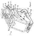
- FIGS 1 and 2 show a first example of a plate compactor 1.
- the compactor 1 is of the type conventionally known as a plate compactor.
- the compactor 1 includes a main body 2 on which is mounted a base plate 3.
- Mounted on the main body 2 is a motor 4.
- the output from the motor 4 drives a conventional vibration generating mechanism via a drive belt contained in a drive belt housing 5.
- Also attached to the main body 2 is a frame 6, which has two mounting assemblies 10 attached at the rear, upper corners 8 of the frame 6.
- the mounting assemblies 10 are used to mount a handle 9 on the frame 6. Interconnecting the mounting assemblies 10 is a weighted cross bar 11.
- the bar 11 typically has a weight of 5kg.
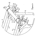
- FIGs 3 and 4 are enlarged side and perspective views respectively of section A of Figure 1 .
- the mounting assemblies 10 each include two rubber bushes 12, a frame plate 7 and a handle mounting plate 13.
- the plates 7 are attached to the upper corners 8 of the frame 6, for example, by welding of the plates 7 to the upper corners of the frame 6.
- the plates 7, 13 are attached to opposite sides of the rubber bushes 12 by bolts 14 and nuts 15.
- the plate 7 has a flange 16 that engages in a slot 17 in the plate 13. This limits movement of the plate 13 relative to the plate 7 and so limits shear and twisting stresses on the bushes 12.
- the handle is generally U-shaped with the central section of the handle 9 forming a grip section 30.
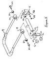
- the ends 19 of the handle 9 are attached to the opposite ends of the bar 11 by bolts 20 that pass through bushings 21 located in the handle ends 19 and holes 22 in the plates 13 and engage with threaded bores 23 in the ends of the bar 11, as shown in Figure 5.
- Figure 5 also shows that the bushes 12 each include a threaded stud 27 that enables the bushes 12 to be attached to the plates 13 by means of a nut 15.
- Figure 6 shows how the bushes 12 attach to the plates 7 by means of bolts 14 that engage with threaded bores 25 in the bushes 12.
- Figure 7 is a cross-section that shows the bushes attached to the plates 7, 13 and the bar 11 and handle ends 19 pivotally coupled to the plates 13.
- the handle 9 is pivoted back about the pivot connection with the plates 13 until the grip section 30 of the handle is behind the mounting assemblies 10. Backward pivoting of the handle 9 is limited by stop 18 on the plates 13.
- the compactor 1 can be used by an operator, who holds the grip section 30 of the handle 9.
- the presence of the rubber bushes 12 helps to mechanically isolate vibration of the compactor main body 2 from the handle 9.
- the vibration is further reduced by the weight in the form of the cross-bar 11 that interconnects ends 19 of the handle 9.
- the bar 11 helps to increase the rigidity of the handle 9. As the bar 11 is concentric with the pivoting point of the handle 9, an operator is not fatigued by having to lift the weight of the bar 11 on the handle as the weight of the bar 11 is balanced on the handle 9.
- FIGS 8 and 9 show a second example of a plate compactor 41.
- the compactor 41 is also of the type conventionally known as a plate compactor and is generally similar in basic construction and operation to the compactor 1 described above.
- the compactor 41 includes a main body 42 on which is mounted a base plate 43.
- Mounted on the main body 42 is a motor 44.
- the output from the motor 44 drives a conventional vibration generating mechanism via a drive belt contained in a drive belt housing 45.
- Mounted on the rear of the main body 42 are two mounting assemblies 410.
- the mounting assemblies 410 are used to mount a handle 49 on the main body 42. Interconnecting the mounting assemblies 410 is a weighted cross bar 411.
- the bar 411 typically has a weight of 5kg.
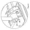
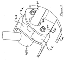
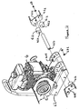
- FIGs 10 and 11 show the mounting assemblies 410 in more detail and Figure 12 shows an exploded view of the mounting assemblies 410 and the cross bar 411.
- the mounting assemblies 410 each include two rubber bushes 412, a main body plate 47 and a handle mounting plate 413.
- the plates 47, 413 are attached to opposite sides of the rubber bushes 412 by bolts 414 and nuts 415.
- the plate 47 has an aperture 416 through which the bar 411 extends.
- the aperture 416 is of a size such that flexing of the rubber bushes 412 is permitted but limits movement of the bar 411 and therefore, plate 413 relative to the plate 47 so that excessive shear and twisting stresses are not applied to the rubber bushes 412.
- Pivotally mounted on the plates 413 are respective ends 419 of the handle 49.
- the ends 419 of the handle 49 are attached to the opposite ends of the bar 411 by bolts 420 that pass through bushings 421 located in the handle ends 419 and holes 422 in the plates 413 and engage with threaded bores 423 in the ends of the bar 411, as shown in Figure 12.
- Figure 12 also shows that the bushes 412 each include a threaded stud 427 that enables the bushes 412 to be attached to the plates 47 by means of a nut 415.
- the bushes 412 attach to the plates 413 by means of bolts 414 that engage with threaded bores (not shown) in the bushes 412.
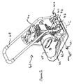
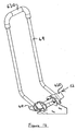
- the handle 49 In use, the handle 49 is stored in the position shown in Figure 8 where the handle rests against forward stop 435 on the plates 413. To operate the compactor 41 the handle 49 is pivoted back about the pivot connection with the plates 413 until grip section 430 of the handle is behind the mounting assemblies 410, as shown in Figures 13 and 14 . Backward pivoting of the handle 49 is limited by stop 418 on the plates 413. When the motor 44 is started the compactor 41 can be used by an operator, who holds the grip section 430 of the handle 49.
- the presence of the rubber bushes 412 helps to mechanically isolate vibration of the compactor main body 42 from the handle 49.
- the vibration is further reduced by the weight in the form of the cross-bar 411 that interconnects ends 419 of the handle 49.
- the bar 411 helps to increase the rigidity of the handle 49. As the bar 411 is concentric with the pivoting point of the handle 49, an operator is not fatigued by having to lift the weight of the bar 411 on the handle, as the weight of the bar 411 is balanced on the handle 49.
- the plate compactors 1, 41 are particularly useful for compaction of ground material, especially where the ground material is: (i) a granular material, such as gravel, soil, sand, hardcore or other aggregates; and/or (ii) a paving material, such as paving block, paving slab flagstones or asphalt.
- the compactors can also be used for other applications that require a downward force to be exerted on a surface, such as during the installation of waterproof membranes on a surface.
- An advantage of the invention is that by reducing vibration of the handles of the compactor, the vibration experienced by an operator is also reduced and this helps to prolong the period that an operator can safely use the compactors 1, 41 without suffering from VWF without affecting the efficiency of the compactors 1, 41.
Landscapes
- Engineering & Computer Science (AREA)
- Structural Engineering (AREA)
- Life Sciences & Earth Sciences (AREA)
- Civil Engineering (AREA)
- Agronomy & Crop Science (AREA)
- Mechanical Engineering (AREA)
- Architecture (AREA)
- Environmental & Geological Engineering (AREA)
- Soil Sciences (AREA)
- General Life Sciences & Earth Sciences (AREA)
- Mining & Mineral Resources (AREA)
- Paleontology (AREA)
- General Engineering & Computer Science (AREA)
- Road Paving Machines (AREA)
- Dry Formation Of Fiberboard And The Like (AREA)
Abstract
Description
- The invention relates to a compactor and especially, a ground compactor for compaction of granular materials, such as gravel, soil, sand, hardcore materials and other aggregates, and/or paving materials such as paving block, paving slabs, flagstones and asphalt.
- Conventional plate compactors use a motor, such as a petrol or diesel engine to vibrate a base plate below the motor. The base plate is generally weighted to increase the compaction of the material to be compacted. The compactor includes a handle which is held by an operator to control the movement of the compactor across the material being compacted. Hence, the handle is also subject to the vibration generated by the compactor.
- This vibration can cause a medical condition known as vibration induced white finger (VWF) which can result in loss of ability to grip properly. Therefore, the vibration of compactors limits the safe working time that an operator can continually use the compactor.
- Disclosed in patent document
US-4 113 403 is a compactor provided with shock absorbers for reducing vibration of the handle and fatigue of the operator.
Disclosed inpatent document EP 1 127 983 is a compactor being provided with a vibration damped bracket handle. In addition to rubber buffers connected at the free ends of the handle, it is also provided with a damping mass extending between the two ends of the handle. - The object of the invention is to reduce the vibration of the handle of a compactor.
- In accordance with the invention, there is provided a compactor comprising a support member, a base plate mounted for vibration on the support member, a motor mounted on the support member, the output of the motor being coupled to the base plate to cause in use, vibration of the base plate,, a handle and a mounting device to mount the handle on the support member, the mounting device comprising an elastomeric member, the support member being coupled to one side of the elastomeric member and the handle being pivotally coupled to the other side of the elastomeric member, characterised in that a mass is mounted on the mounting device, the centre of weight of the mass substantially coinciding with the pivoting axis of the handle.
- An advantage of the invention is that vibration of the handle of a compactor can be reduced by coupling the handle to the support member via an elastomeric member and by providing a mass centred on the pivoting axis of the handle.
- Preferably, the mass is located on the handle side of the elastomeric member.
- Typically, the pivotal axis of the handle is offset from the central axis of the elastomeric member.
- Preferably, the mounting device comprises a first mounting plate and a second mounting plate, the elastomeric member being located between the mounting plates and the first mounting plate having the support member coupled thereto and the second mounting plate having the handle coupled thereto.
- Typically, the support member is fixedly attached to the first mounting plate.
- Typically, the handle is pivotally coupled to the second mounting plate.
- The mounting device may comprise a stop to limit pivoting movement of the handle in one direction. In one example of the invention the mounting device comprises two stops to limit pivoting movement of the handle in both directions. Typically, where the mounting device includes first and second plates, the stop (or stops) are formed on the second mounting plate.
- Preferably, the mounting device comprises two elastomeric members, and the support member is coupled to a side of each elastomeric member and the handle is coupled to the opposite sides of the elastomeric members. Where the mounting device includes first and second mounting plates, the elastomeric members are located between the mounting plates in side-by-side arrangement. It is also possible that more than two elastomeric members could be used.
- Typically, the handle may be coupled to the support member at two separate locations, each location having a separate mounting device. The handle may comprise two leg sections, each leg section being coupled to the support member by a mounting device. For example, the handle could be generally U-shaped, with each leg of the U being coupled to the support member by a separate coupling device, and the central portion of the U forming a grip section to be held by an operator.
- Preferably, where the handle has two legs, both legs being coupled to the support member, the mass is located between the legs of the handle and is coincident with the pivoting axis of the handle. For example, the mass may be in the form of a cross bar between the pivot points of the handle. This has the additional advantage of helping to increase the rigidity of the handle.
- Preferably, the mass has weight of at least 2kg, and preferably at least 5kg.
- Typically, the elastomeric member may be cylindrical with an end of the cylinder coupled to the support member and the other end of the cylinder coupled to the handle. The elastomeric member may be manufactured from an elastomeric material, such as rubber or another material having rubber-like mechanical properties.
- Examples of a compactor in accordance with the invention will now be described with reference to the accompanying drawings, in which:
-
Figure 1 is a perspective view from the front and side of a first example of a plate compactor with a handle in a folded position; -
Figure 2 is a rear view of the compactor shown inFigure 1 ; -
Figure 3 is an enlarged side view of the section A inFigure 1 ; -
Figure 4 is a perspective view from the side and rear of section A; -
Figure 5 is an exploded view of the handle and mounting assembly of the compactor shown inFigure 1 ; -
Figure 6 is an exploded view showing the connection of the handle and mounting assembly to the compactor; -
Figure 7 is a cross-sectional view along the line BB ofFigure 3 ; -
Figure 8 is a perspective view from the front and side of a second example of a plate compactor with a handle in a folded position; -
Figure 9 is a perspective view from the side and rear of the compactor shown inFigure 8 ; -
Figure 10 is an enlarged view of section C inFigure 9 ; -
Figure 11 is an enlarged view of section C from a different angle; -
Figure 12 is an exploded view of a mounting assembly for the compactor of -
Figures 8 and9 with the handle omitted for clarity. -
Figure 13 is a side of a part of the compactor ofFigures 8 and9 with the handle in an operating position; and -
Figure 14 is a perspective view of the part of the compactor shown inFigure 13 ; -
Figures 1 and2 show a first example of a plate compactor 1. The compactor 1 is of the type conventionally known as a plate compactor. The compactor 1 includes amain body 2 on which is mounted abase plate 3. Mounted on themain body 2 is amotor 4. The output from themotor 4 drives a conventional vibration generating mechanism via a drive belt contained in adrive belt housing 5. Also attached to themain body 2 is aframe 6, which has twomounting assemblies 10 attached at the rear, upper corners 8 of theframe 6. - The
mounting assemblies 10 are used to mount a handle 9 on theframe 6. Interconnecting themounting assemblies 10 is aweighted cross bar 11. Thebar 11 typically has a weight of 5kg. -
Figures 3 and4 are enlarged side and perspective views respectively of section A ofFigure 1 . These figures show themounting assemblies 10 in more detail. Themounting assemblies 10 each include tworubber bushes 12, aframe plate 7 and ahandle mounting plate 13. Theplates 7 are attached to the upper corners 8 of theframe 6, for example, by welding of theplates 7 to the upper corners of theframe 6. Theplates rubber bushes 12 bybolts 14 andnuts 15. In addition, theplate 7 has aflange 16 that engages in aslot 17 in theplate 13. This limits movement of theplate 13 relative to theplate 7 and so limits shear and twisting stresses on thebushes 12. - Pivotally mounted on the
plates 13 arerespective ends 19 of the handle 9. The handle is generally U-shaped with the central section of the handle 9 forming a grip section 30. The ends 19 of the handle 9 are attached to the opposite ends of thebar 11 bybolts 20 that pass throughbushings 21 located in the handle ends 19 and holes 22 in theplates 13 and engage with threadedbores 23 in the ends of thebar 11, as shown inFigure 5. Figure 5 also shows that thebushes 12 each include a threadedstud 27 that enables thebushes 12 to be attached to theplates 13 by means of anut 15.Figure 6 shows how thebushes 12 attach to theplates 7 by means ofbolts 14 that engage with threadedbores 25 in thebushes 12.Figure 7 is a cross-section that shows the bushes attached to theplates bar 11 and handle ends 19 pivotally coupled to theplates 13. - In use, the handle 9 is pivoted back about the pivot connection with the
plates 13 until the grip section 30 of the handle is behind the mountingassemblies 10. Backward pivoting of the handle 9 is limited bystop 18 on theplates 13. When themotor 4 is started the compactor 1 can be used by an operator, who holds the grip section 30 of the handle 9. - During operation the presence of the
rubber bushes 12 helps to mechanically isolate vibration of the compactormain body 2 from the handle 9. In addition the vibration is further reduced by the weight in the form of the cross-bar 11 that interconnects ends 19 of the handle 9. In addition, thebar 11 helps to increase the rigidity of the handle 9. As thebar 11 is concentric with the pivoting point of the handle 9, an operator is not fatigued by having to lift the weight of thebar 11 on the handle as the weight of thebar 11 is balanced on the handle 9. -
Figures 8 and9 show a second example of aplate compactor 41. Thecompactor 41 is also of the type conventionally known as a plate compactor and is generally similar in basic construction and operation to the compactor 1 described above. Thecompactor 41 includes amain body 42 on which is mounted abase plate 43. Mounted on themain body 42 is amotor 44. The output from themotor 44 drives a conventional vibration generating mechanism via a drive belt contained in adrive belt housing 45. Mounted on the rear of themain body 42 are two mountingassemblies 410. - The mounting
assemblies 410 are used to mount ahandle 49 on themain body 42. Interconnecting the mountingassemblies 410 is aweighted cross bar 411. Thebar 411 typically has a weight of 5kg. -
Figures 10 and11 show the mountingassemblies 410 in more detail andFigure 12 shows an exploded view of the mountingassemblies 410 and thecross bar 411. The mountingassemblies 410 each include tworubber bushes 412, amain body plate 47 and ahandle mounting plate 413. Theplates rubber bushes 412 by bolts 414 and nuts 415. In addition, theplate 47 has an aperture 416 through which thebar 411 extends. The aperture 416 is of a size such that flexing of therubber bushes 412 is permitted but limits movement of thebar 411 and therefore,plate 413 relative to theplate 47 so that excessive shear and twisting stresses are not applied to therubber bushes 412. - Pivotally mounted on the
plates 413 arerespective ends 419 of thehandle 49. The ends 419 of thehandle 49 are attached to the opposite ends of thebar 411 bybolts 420 that pass through bushings 421 located in the handle ends 419 andholes 422 in theplates 413 and engage with threaded bores 423 in the ends of thebar 411, as shown inFigure 12. Figure 12 also shows that thebushes 412 each include a threadedstud 427 that enables thebushes 412 to be attached to theplates 47 by means of anut 415. Thebushes 412 attach to theplates 413 by means of bolts 414 that engage with threaded bores (not shown) in thebushes 412. - In use, the
handle 49 is stored in the position shown inFigure 8 where the handle rests againstforward stop 435 on theplates 413. To operate thecompactor 41 thehandle 49 is pivoted back about the pivot connection with theplates 413 until grip section 430 of the handle is behind the mountingassemblies 410, as shown inFigures 13 and14 . Backward pivoting of thehandle 49 is limited bystop 418 on theplates 413. When themotor 44 is started thecompactor 41 can be used by an operator, who holds the grip section 430 of thehandle 49. - During operation the presence of the
rubber bushes 412 helps to mechanically isolate vibration of the compactormain body 42 from thehandle 49. In addition the vibration is further reduced by the weight in the form of the cross-bar 411 that interconnects ends 419 of thehandle 49. In addition, thebar 411 helps to increase the rigidity of thehandle 49. As thebar 411 is concentric with the pivoting point of thehandle 49, an operator is not fatigued by having to lift the weight of thebar 411 on the handle, as the weight of thebar 411 is balanced on thehandle 49. - The
plate compactors 1, 41 are particularly useful for compaction of ground material, especially where the ground material is: (i) a granular material, such as gravel, soil, sand, hardcore or other aggregates; and/or (ii) a paving material, such as paving block, paving slab flagstones or asphalt. In addition, the compactors can also be used for other applications that require a downward force to be exerted on a surface, such as during the installation of waterproof membranes on a surface. - An advantage of the invention is that by reducing vibration of the handles of the compactor, the vibration experienced by an operator is also reduced and this helps to prolong the period that an operator can safely use the
compactors 1, 41 without suffering from VWF without affecting the efficiency of thecompactors 1, 41.
Claims (20)
- A compactor (1) comprising a support member (2, 6), a base plate (3) mounted for vibration on the support member (2, 6), a motor (4) mounted on the support member (2, 6), the output of the motor (4) being coupled to the base plate (3) to cause, in use, vibration of the base plate (3), a handle (9) and a mounting device (10) to mount the handle (9) on the support member (2, 6), the mounting device (10) comprising an elastomeric member (12), the support member (2, 6) being coupled to one side of the elastomeric member (12) and the handle (9) being pivotally coupled to the other side of the elastomeric member (12), characterised in that a mass (11) is mounted on the mounting device (10), the centre of weight of the mass (11) substantially coinciding with the pivoting axis of the handle (9).
- A compactor according to claim 1, wherein the mass (11) is located on the handle side of the elastomeric member (12).
- A compactor according to claim 1 or claim 2, wherein the pivotal axis of the handle (9) is offset from the central axis of the elastomeric member (12).
- A compactor according to any of the preceding claims, wherein the mounting device (10) comprises a first mounting plate (7) and a second mounting plate (13), the elastomeric member (12) being located between the mounting plates (7, 13) and the first mounting plate (7) having the support member (2, 6) coupled thereto and the second mounting plate (13) having the handle (9) coupled thereto.
- A compactor according to claim 4, wherein the support member (2, 6) is fixedly attached to the first mounting plate (7).
- A compactor according to claim 4 or claim 5, wherein the handle (9) is pivotally coupled to the second mounting plate (13).
- A compactor according to any of the preceding claims, wherein the mounting device (10) may comprise a stop (18) to limit pivoting movement of the handle (9) in one direction.
- A compactor according to claim 7, wherein the mounting device (410) comprises two stops (418, 435) to limit pivoting movement of the handle (49) in both directions.
- A compactor according to claim 7 or claim 8 when dependent on any of claims 4 to 6, wherein the stop (18) or stops (435, 418) are formed on the second mounting plate (13, 413).
- A compactor according to any of the preceding claims, wherein the mounting device (10) comprises two elastomeric members (12), and the support member (2, 6) is coupled to a side of each elastomeric member (12) and the handle (9) is coupled to the opposite sides of the elastomeric members (12).
- A compactor according to claim 10 when dependent on any of claims 4 to 6, wherein the elastomeric members (12) are located between the mounting plates (7,13) in side-by-side arrangement.
- A compactor according to any of the preceding claims, wherein the handle (9) is coupled to the support member (2, 6) at two separate locations, each location having a separate mounting device (10).
- A compactor according to any of the preceding claims, wherein the handle (9) comprises two leg sections, each leg section being coupled to the support member (2, 6) by a separate mounting device (10).
- A compactor according to claim 13, wherein the handle (9) is generally U-shaped, with each leg of the U being coupled to the support member (2, 6) by a separate mounting device (10), and the central portion of the U forming a grip section.
- A compactor according to claim 13 or claim 14, wherein the mass (11) is located between the legs of the handle (9) and is coincident with the pivoting axis of the handle (9).
- A compactor according to claim 15, wherein the mass (11) is in the form of a cross bar between the pivot points of the handle (9).
- A compactor according to any of the preceding claims, wherein the mass (11) has a weight of at least 2kg.
- A compactor according to any claim 17, wherein the mass (11) has a weight of at least 5kg.
- A compactor according to any of the preceding claims, wherein the elastomeric member (12) is cylindrical with an end of the cylinder coupled to the support member (2, 6) and the other end of the cylinder coupled to the handle (9).
- A compactor according to any of the preceding claims, wherein the elastomeric member (12) is manufactured from an elastomeric material.
Priority Applications (1)
| Application Number | Priority Date | Filing Date | Title |
|---|---|---|---|
| PL05250279T PL1557495T3 (en) | 2004-01-23 | 2005-01-20 | A compactor |
Applications Claiming Priority (2)
| Application Number | Priority Date | Filing Date | Title |
|---|---|---|---|
| GBGB0401421.3A GB0401421D0 (en) | 2004-01-23 | 2004-01-23 | A compactor |
| GB0401421 | 2004-01-23 |
Publications (3)
| Publication Number | Publication Date |
|---|---|
| EP1557495A2 EP1557495A2 (en) | 2005-07-27 |
| EP1557495A3 EP1557495A3 (en) | 2007-07-18 |
| EP1557495B1 true EP1557495B1 (en) | 2011-06-22 |
Family
ID=31971298
Family Applications (1)
| Application Number | Title | Priority Date | Filing Date |
|---|---|---|---|
| EP05250279A Expired - Lifetime EP1557495B1 (en) | 2004-01-23 | 2005-01-20 | A compactor |
Country Status (4)
| Country | Link |
|---|---|
| EP (1) | EP1557495B1 (en) |
| AT (1) | ATE513950T1 (en) |
| GB (2) | GB0401421D0 (en) |
| PL (1) | PL1557495T3 (en) |
Families Citing this family (1)
| Publication number | Priority date | Publication date | Assignee | Title |
|---|---|---|---|---|
| DE202009000264U1 (en) | 2008-02-01 | 2009-03-26 | Ammann Verdichtung Gmbh | damping element |
Family Cites Families (4)
| Publication number | Priority date | Publication date | Assignee | Title |
|---|---|---|---|---|
| BE654553A (en) * | 1963-10-19 | |||
| US4113403A (en) * | 1977-08-31 | 1978-09-12 | Stone Construction Equipment Inc. | Plate type compactor |
| GB2356235A (en) * | 1999-11-13 | 2001-05-16 | Benford Ltd | Compactor machine |
| DE10007869C1 (en) * | 2000-02-21 | 2001-08-23 | Ammann Verdichtung Gmbh | Vibrating plate |
-
2004
- 2004-01-23 GB GBGB0401421.3A patent/GB0401421D0/en not_active Ceased
-
2005
- 2005-01-20 AT AT05250279T patent/ATE513950T1/en not_active IP Right Cessation
- 2005-01-20 EP EP05250279A patent/EP1557495B1/en not_active Expired - Lifetime
- 2005-01-20 PL PL05250279T patent/PL1557495T3/en unknown
- 2005-01-20 GB GB0501291A patent/GB2410284B/en not_active Expired - Lifetime
Also Published As
| Publication number | Publication date |
|---|---|
| EP1557495A2 (en) | 2005-07-27 |
| PL1557495T3 (en) | 2011-12-30 |
| GB0401421D0 (en) | 2004-02-25 |
| EP1557495A3 (en) | 2007-07-18 |
| GB2410284B (en) | 2009-05-20 |
| GB2410284A (en) | 2005-07-27 |
| GB0501291D0 (en) | 2005-03-02 |
| ATE513950T1 (en) | 2011-07-15 |
Similar Documents
| Publication | Publication Date | Title |
|---|---|---|
| US6749365B2 (en) | Vibration isolation for a percussion rammer | |
| US6588977B1 (en) | Compactor machine having vibration damping means | |
| EP1627960B1 (en) | Breaker mounting bracket | |
| US20090035065A1 (en) | Compactor | |
| US3824417A (en) | Handle mounting construction for electric paving breaker | |
| CN221545201U (en) | Plate compactor | |
| GB2455627A (en) | Electric compactor | |
| WO2020202585A1 (en) | Ground consolidation device | |
| US4170427A (en) | Vibrating tamper | |
| JP4022256B2 (en) | Vibration-damping machine drive tool | |
| US4515408A (en) | Counterweight support for resonantly driven tool | |
| KR20140074847A (en) | Hydraulic Vibratory Ripper | |
| US20150204415A1 (en) | Vibration isolation assembly for concrete saws | |
| EP1557495A2 (en) | A compactor | |
| US5716162A (en) | Dual-stage mounting system for vibratory compactor drum | |
| GB2226616A (en) | Improved vibratory mechanism for a compaction roller | |
| US12098518B2 (en) | Vibration ripper having link structure with improved vibration isolating function | |
| US3236164A (en) | Material compacting device | |
| JP3635389B2 (en) | Diaphragm device | |
| US4340255A (en) | Resonantly driven vertical impact system | |
| KR102004443B1 (en) | a tie tamper having a improvement for tamp performance | |
| CA3121796C (en) | Vibration ripper having link structure with improved vibration isolating function | |
| JPH0516246Y2 (en) | ||
| JPH07119105A (en) | Tamping device | |
| JP2016216939A (en) | Anti-vibration device for plate compactor |
Legal Events
| Date | Code | Title | Description |
|---|---|---|---|
| PUAI | Public reference made under article 153(3) epc to a published international application that has entered the european phase |
Free format text: ORIGINAL CODE: 0009012 |
|
| AK | Designated contracting states |
Kind code of ref document: A2 Designated state(s): AT BE BG CH CY CZ DE DK EE ES FI FR GB GR HU IE IS IT LI LT LU MC NL PL PT RO SE SI SK TR |
|
| AX | Request for extension of the european patent |
Extension state: AL BA HR LV MK YU |
|
| PUAL | Search report despatched |
Free format text: ORIGINAL CODE: 0009013 |
|
| AK | Designated contracting states |
Kind code of ref document: A3 Designated state(s): AT BE BG CH CY CZ DE DK EE ES FI FR GB GR HU IE IS IT LI LT LU MC NL PL PT RO SE SI SK TR |
|
| AX | Request for extension of the european patent |
Extension state: AL BA HR LV MK YU |
|
| RIC1 | Information provided on ipc code assigned before grant |
Ipc: E01C 19/38 20060101ALI20070612BHEP Ipc: E02D 3/074 20060101AFI20050425BHEP Ipc: B25D 17/04 20060101ALI20070612BHEP |
|
| 17P | Request for examination filed |
Effective date: 20080118 |
|
| AKX | Designation fees paid |
Designated state(s): AT BE BG CH CY CZ DE DK EE ES FI FR GB GR HU IE IS IT LI LT LU MC NL PL PT RO SE SI SK TR |
|
| GRAJ | Information related to disapproval of communication of intention to grant by the applicant or resumption of examination proceedings by the epo deleted |
Free format text: ORIGINAL CODE: EPIDOSDIGR1 |
|
| GRAP | Despatch of communication of intention to grant a patent |
Free format text: ORIGINAL CODE: EPIDOSNIGR1 |
|
| GRAP | Despatch of communication of intention to grant a patent |
Free format text: ORIGINAL CODE: EPIDOSNIGR1 |
|
| RBV | Designated contracting states (corrected) |
Designated state(s): AT BE BG CH CY CZ DE DK EE ES FI FR GR HU IE IS IT LI LT LU MC NL PL PT RO SE SI SK TR |
|
| GRAS | Grant fee paid |
Free format text: ORIGINAL CODE: EPIDOSNIGR3 |
|
| GRAA | (expected) grant |
Free format text: ORIGINAL CODE: 0009210 |
|
| AK | Designated contracting states |
Kind code of ref document: B1 Designated state(s): AT BE BG CH CY CZ DE DK EE ES FI FR GR HU IE IS IT LI LT LU MC NL PL PT RO SE SI SK TR |
|
| REG | Reference to a national code |
Ref country code: CH Ref legal event code: EP |
|
| REG | Reference to a national code |
Ref country code: IE Ref legal event code: FG4D |
|
| REG | Reference to a national code |
Ref country code: DE Ref legal event code: R096 Ref document number: 602005028615 Country of ref document: DE Effective date: 20110811 |
|
| REG | Reference to a national code |
Ref country code: NL Ref legal event code: VDEP Effective date: 20110622 |
|
| PG25 | Lapsed in a contracting state [announced via postgrant information from national office to epo] |
Ref country code: SE Free format text: LAPSE BECAUSE OF FAILURE TO SUBMIT A TRANSLATION OF THE DESCRIPTION OR TO PAY THE FEE WITHIN THE PRESCRIBED TIME-LIMIT Effective date: 20110622 Ref country code: LT Free format text: LAPSE BECAUSE OF FAILURE TO SUBMIT A TRANSLATION OF THE DESCRIPTION OR TO PAY THE FEE WITHIN THE PRESCRIBED TIME-LIMIT Effective date: 20110622 |
|
| PG25 | Lapsed in a contracting state [announced via postgrant information from national office to epo] |
Ref country code: CY Free format text: LAPSE BECAUSE OF FAILURE TO SUBMIT A TRANSLATION OF THE DESCRIPTION OR TO PAY THE FEE WITHIN THE PRESCRIBED TIME-LIMIT Effective date: 20110622 Ref country code: GR Free format text: LAPSE BECAUSE OF FAILURE TO SUBMIT A TRANSLATION OF THE DESCRIPTION OR TO PAY THE FEE WITHIN THE PRESCRIBED TIME-LIMIT Effective date: 20110923 Ref country code: AT Free format text: LAPSE BECAUSE OF FAILURE TO SUBMIT A TRANSLATION OF THE DESCRIPTION OR TO PAY THE FEE WITHIN THE PRESCRIBED TIME-LIMIT Effective date: 20110622 Ref country code: FI Free format text: LAPSE BECAUSE OF FAILURE TO SUBMIT A TRANSLATION OF THE DESCRIPTION OR TO PAY THE FEE WITHIN THE PRESCRIBED TIME-LIMIT Effective date: 20110622 Ref country code: SI Free format text: LAPSE BECAUSE OF FAILURE TO SUBMIT A TRANSLATION OF THE DESCRIPTION OR TO PAY THE FEE WITHIN THE PRESCRIBED TIME-LIMIT Effective date: 20110622 |
|
| PG25 | Lapsed in a contracting state [announced via postgrant information from national office to epo] |
Ref country code: NL Free format text: LAPSE BECAUSE OF FAILURE TO SUBMIT A TRANSLATION OF THE DESCRIPTION OR TO PAY THE FEE WITHIN THE PRESCRIBED TIME-LIMIT Effective date: 20110622 Ref country code: BE Free format text: LAPSE BECAUSE OF FAILURE TO SUBMIT A TRANSLATION OF THE DESCRIPTION OR TO PAY THE FEE WITHIN THE PRESCRIBED TIME-LIMIT Effective date: 20110622 |
|
| REG | Reference to a national code |
Ref country code: PL Ref legal event code: T3 |
|
| PG25 | Lapsed in a contracting state [announced via postgrant information from national office to epo] |
Ref country code: CZ Free format text: LAPSE BECAUSE OF FAILURE TO SUBMIT A TRANSLATION OF THE DESCRIPTION OR TO PAY THE FEE WITHIN THE PRESCRIBED TIME-LIMIT Effective date: 20110622 Ref country code: PT Free format text: LAPSE BECAUSE OF FAILURE TO SUBMIT A TRANSLATION OF THE DESCRIPTION OR TO PAY THE FEE WITHIN THE PRESCRIBED TIME-LIMIT Effective date: 20111024 Ref country code: IS Free format text: LAPSE BECAUSE OF FAILURE TO SUBMIT A TRANSLATION OF THE DESCRIPTION OR TO PAY THE FEE WITHIN THE PRESCRIBED TIME-LIMIT Effective date: 20111022 Ref country code: EE Free format text: LAPSE BECAUSE OF FAILURE TO SUBMIT A TRANSLATION OF THE DESCRIPTION OR TO PAY THE FEE WITHIN THE PRESCRIBED TIME-LIMIT Effective date: 20110622 |
|
| PG25 | Lapsed in a contracting state [announced via postgrant information from national office to epo] |
Ref country code: RO Free format text: LAPSE BECAUSE OF FAILURE TO SUBMIT A TRANSLATION OF THE DESCRIPTION OR TO PAY THE FEE WITHIN THE PRESCRIBED TIME-LIMIT Effective date: 20110622 Ref country code: SK Free format text: LAPSE BECAUSE OF FAILURE TO SUBMIT A TRANSLATION OF THE DESCRIPTION OR TO PAY THE FEE WITHIN THE PRESCRIBED TIME-LIMIT Effective date: 20110622 |
|
| PLBE | No opposition filed within time limit |
Free format text: ORIGINAL CODE: 0009261 |
|
| STAA | Information on the status of an ep patent application or granted ep patent |
Free format text: STATUS: NO OPPOSITION FILED WITHIN TIME LIMIT |
|
| 26N | No opposition filed |
Effective date: 20120323 |
|
| PG25 | Lapsed in a contracting state [announced via postgrant information from national office to epo] |
Ref country code: IT Free format text: LAPSE BECAUSE OF FAILURE TO SUBMIT A TRANSLATION OF THE DESCRIPTION OR TO PAY THE FEE WITHIN THE PRESCRIBED TIME-LIMIT Effective date: 20110622 |
|
| PG25 | Lapsed in a contracting state [announced via postgrant information from national office to epo] |
Ref country code: DK Free format text: LAPSE BECAUSE OF FAILURE TO SUBMIT A TRANSLATION OF THE DESCRIPTION OR TO PAY THE FEE WITHIN THE PRESCRIBED TIME-LIMIT Effective date: 20110622 |
|
| REG | Reference to a national code |
Ref country code: DE Ref legal event code: R097 Ref document number: 602005028615 Country of ref document: DE Effective date: 20120323 |
|
| PG25 | Lapsed in a contracting state [announced via postgrant information from national office to epo] |
Ref country code: MC Free format text: LAPSE BECAUSE OF NON-PAYMENT OF DUE FEES Effective date: 20120131 |
|
| REG | Reference to a national code |
Ref country code: CH Ref legal event code: PL |
|
| REG | Reference to a national code |
Ref country code: IE Ref legal event code: MM4A |
|
| PG25 | Lapsed in a contracting state [announced via postgrant information from national office to epo] |
Ref country code: LI Free format text: LAPSE BECAUSE OF NON-PAYMENT OF DUE FEES Effective date: 20120131 Ref country code: CH Free format text: LAPSE BECAUSE OF NON-PAYMENT OF DUE FEES Effective date: 20120131 |
|
| PG25 | Lapsed in a contracting state [announced via postgrant information from national office to epo] |
Ref country code: IE Free format text: LAPSE BECAUSE OF NON-PAYMENT OF DUE FEES Effective date: 20120120 |
|
| PG25 | Lapsed in a contracting state [announced via postgrant information from national office to epo] |
Ref country code: ES Free format text: LAPSE BECAUSE OF FAILURE TO SUBMIT A TRANSLATION OF THE DESCRIPTION OR TO PAY THE FEE WITHIN THE PRESCRIBED TIME-LIMIT Effective date: 20111003 |
|
| PG25 | Lapsed in a contracting state [announced via postgrant information from national office to epo] |
Ref country code: BG Free format text: LAPSE BECAUSE OF FAILURE TO SUBMIT A TRANSLATION OF THE DESCRIPTION OR TO PAY THE FEE WITHIN THE PRESCRIBED TIME-LIMIT Effective date: 20110922 |
|
| PG25 | Lapsed in a contracting state [announced via postgrant information from national office to epo] |
Ref country code: TR Free format text: LAPSE BECAUSE OF FAILURE TO SUBMIT A TRANSLATION OF THE DESCRIPTION OR TO PAY THE FEE WITHIN THE PRESCRIBED TIME-LIMIT Effective date: 20110622 |
|
| PG25 | Lapsed in a contracting state [announced via postgrant information from national office to epo] |
Ref country code: LU Free format text: LAPSE BECAUSE OF NON-PAYMENT OF DUE FEES Effective date: 20120120 |
|
| PG25 | Lapsed in a contracting state [announced via postgrant information from national office to epo] |
Ref country code: HU Free format text: LAPSE BECAUSE OF FAILURE TO SUBMIT A TRANSLATION OF THE DESCRIPTION OR TO PAY THE FEE WITHIN THE PRESCRIBED TIME-LIMIT Effective date: 20050120 |
|
| REG | Reference to a national code |
Ref country code: FR Ref legal event code: PLFP Year of fee payment: 12 |
|
| REG | Reference to a national code |
Ref country code: FR Ref legal event code: PLFP Year of fee payment: 13 |
|
| REG | Reference to a national code |
Ref country code: FR Ref legal event code: PLFP Year of fee payment: 14 |
|
| PGFP | Annual fee paid to national office [announced via postgrant information from national office to epo] |
Ref country code: DE Payment date: 20240227 Year of fee payment: 20 |
|
| PGFP | Annual fee paid to national office [announced via postgrant information from national office to epo] |
Ref country code: PL Payment date: 20240228 Year of fee payment: 20 Ref country code: FR Payment date: 20240227 Year of fee payment: 20 |
|
| REG | Reference to a national code |
Ref country code: DE Ref legal event code: R071 Ref document number: 602005028615 Country of ref document: DE |