EP1557352B1 - System zur Übergabe von Flüssigkeiten auf See - Google Patents
System zur Übergabe von Flüssigkeiten auf See Download PDFInfo
- Publication number
- EP1557352B1 EP1557352B1 EP05008023A EP05008023A EP1557352B1 EP 1557352 B1 EP1557352 B1 EP 1557352B1 EP 05008023 A EP05008023 A EP 05008023A EP 05008023 A EP05008023 A EP 05008023A EP 1557352 B1 EP1557352 B1 EP 1557352B1
- Authority
- EP
- European Patent Office
- Prior art keywords
- vessel
- arm
- loading
- mooring
- fluid
- Prior art date
- Legal status (The legal status is an assumption and is not a legal conclusion. Google has not performed a legal analysis and makes no representation as to the accuracy of the status listed.)
- Expired - Lifetime
Links
- 239000012530 fluid Substances 0.000 title claims description 42
- 238000012546 transfer Methods 0.000 title claims description 29
- 238000000926 separation method Methods 0.000 claims description 17
- 238000010276 construction Methods 0.000 claims description 8
- 238000007689 inspection Methods 0.000 claims description 8
- 238000000034 method Methods 0.000 claims description 8
- 238000012544 monitoring process Methods 0.000 claims description 8
- 238000012423 maintenance Methods 0.000 claims description 7
- 238000009413 insulation Methods 0.000 claims description 3
- 230000002093 peripheral effect Effects 0.000 claims description 2
- XLYOFNOQVPJJNP-UHFFFAOYSA-N water Substances O XLYOFNOQVPJJNP-UHFFFAOYSA-N 0.000 description 5
- 238000010586 diagram Methods 0.000 description 4
- 238000012806 monitoring device Methods 0.000 description 3
- 238000004519 manufacturing process Methods 0.000 description 2
- 229910000831 Steel Inorganic materials 0.000 description 1
- 238000013461 design Methods 0.000 description 1
- 238000005188 flotation Methods 0.000 description 1
- 231100001261 hazardous Toxicity 0.000 description 1
- 239000003949 liquefied natural gas Substances 0.000 description 1
- 238000012986 modification Methods 0.000 description 1
- 230000004048 modification Effects 0.000 description 1
- 239000010959 steel Substances 0.000 description 1
- 230000000007 visual effect Effects 0.000 description 1
Images
Classifications
-
- B—PERFORMING OPERATIONS; TRANSPORTING
- B67—OPENING, CLOSING OR CLEANING BOTTLES, JARS OR SIMILAR CONTAINERS; LIQUID HANDLING
- B67D—DISPENSING, DELIVERING OR TRANSFERRING LIQUIDS, NOT OTHERWISE PROVIDED FOR
- B67D9/00—Apparatus or devices for transferring liquids when loading or unloading ships
-
- B—PERFORMING OPERATIONS; TRANSPORTING
- B63—SHIPS OR OTHER WATERBORNE VESSELS; RELATED EQUIPMENT
- B63B—SHIPS OR OTHER WATERBORNE VESSELS; EQUIPMENT FOR SHIPPING
- B63B27/00—Arrangement of ship-based loading or unloading equipment for cargo or passengers
- B63B27/24—Arrangement of ship-based loading or unloading equipment for cargo or passengers of pipe-lines
-
- B—PERFORMING OPERATIONS; TRANSPORTING
- B63—SHIPS OR OTHER WATERBORNE VESSELS; RELATED EQUIPMENT
- B63B—SHIPS OR OTHER WATERBORNE VESSELS; EQUIPMENT FOR SHIPPING
- B63B27/00—Arrangement of ship-based loading or unloading equipment for cargo or passengers
- B63B27/30—Arrangement of ship-based loading or unloading equipment for transfer at sea between ships or between ships and off-shore structures
- B63B27/34—Arrangement of ship-based loading or unloading equipment for transfer at sea between ships or between ships and off-shore structures using pipe-lines
-
- B—PERFORMING OPERATIONS; TRANSPORTING
- B63—SHIPS OR OTHER WATERBORNE VESSELS; RELATED EQUIPMENT
- B63B—SHIPS OR OTHER WATERBORNE VESSELS; EQUIPMENT FOR SHIPPING
- B63B43/00—Improving safety of vessels, e.g. damage control, not otherwise provided for
- B63B43/18—Improving safety of vessels, e.g. damage control, not otherwise provided for preventing collision or grounding; reducing collision damage
-
- B—PERFORMING OPERATIONS; TRANSPORTING
- B63—SHIPS OR OTHER WATERBORNE VESSELS; RELATED EQUIPMENT
- B63B—SHIPS OR OTHER WATERBORNE VESSELS; EQUIPMENT FOR SHIPPING
- B63B35/00—Vessels or similar floating structures specially adapted for specific purposes and not otherwise provided for
- B63B35/44—Floating buildings, stores, drilling platforms, or workshops, e.g. carrying water-oil separating devices
- B63B2035/448—Floating hydrocarbon production vessels, e.g. Floating Production Storage and Offloading vessels [FPSO]
-
- B—PERFORMING OPERATIONS; TRANSPORTING
- B63—SHIPS OR OTHER WATERBORNE VESSELS; RELATED EQUIPMENT
- B63B—SHIPS OR OTHER WATERBORNE VESSELS; EQUIPMENT FOR SHIPPING
- B63B21/00—Tying-up; Shifting, towing, or pushing equipment; Anchoring
-
- B—PERFORMING OPERATIONS; TRANSPORTING
- B63—SHIPS OR OTHER WATERBORNE VESSELS; RELATED EQUIPMENT
- B63B—SHIPS OR OTHER WATERBORNE VESSELS; EQUIPMENT FOR SHIPPING
- B63B22/00—Buoys
- B63B22/02—Buoys specially adapted for mooring a vessel
- B63B22/021—Buoys specially adapted for mooring a vessel and for transferring fluids, e.g. liquids
-
- B—PERFORMING OPERATIONS; TRANSPORTING
- B63—SHIPS OR OTHER WATERBORNE VESSELS; RELATED EQUIPMENT
- B63H—MARINE PROPULSION OR STEERING
- B63H25/00—Steering; Slowing-down otherwise than by use of propulsive elements; Dynamic anchoring, i.e. positioning vessels by means of main or auxiliary propulsive elements
- B63H25/46—Steering or dynamic anchoring by jets or by rudders carrying jets
Definitions
- the present invention relates to a method and an apparatus for transferring fluid between two floating vessels.
- a further disadvantage is that because the rigid arm is submerged, inspection, maintenance and repair operation are more difficult to carry out.
- the present invention as claimed in claim 1 provides an Apparatus for transferring fluid between first and second floating vessels, comprising a submerged rigid transfer arm, at least one fluid pipeline for transferring fluid between the first and second vessels, the pipeline located in a conduit mounted on the arm, means to attach a first end of the arm to the first vessel so as to allow the arm to pivot about three axes, and loading means located at the second end of the arm and attachable to the second vessel for transferring fluid from the fluid pipeline to the second vessel; characterised in that the conduit has an opening at each end which is above the waterline and the means to attach a first end of the arm to the first vessel is at a position above the waterline in use.
- the rigid arm may be a space frame construction having a plurality of longitudinal members joined by a plurality of transverse bracing members.
- the fluid pipeline is located inside a conduit formed at least in part by one of the longitudinal members. Insulation may be provided around the fluid pipeline.
- the conduit is configured to allow access thereinto for inspection and maintenance of the fluid pipeline.
- the apparatus is also provided with thrust means operable to rotate the rigid arm relative to the first vessel about a substantially vertical axis in use, position monitoring means to monitor the separation of a point on the arm and the second vessel, and a control system operable to actuate the thrust means if the separation is outside a predetermined range, so as to move the arm relative to the second vessel thereby to restore the separation to within the predetermined range.
- thrust means operable to rotate the rigid arm relative to the first vessel about a substantially vertical axis in use
- position monitoring means to monitor the separation of a point on the arm and the second vessel
- a control system operable to actuate the thrust means if the separation is outside a predetermined range, so as to move the arm relative to the second vessel thereby to restore the separation to within the predetermined range.
- the apparatus may usefully comprise mooring means to moor the apparatus to the second vessel, means to monitor whether the mooring means is attached to the floating vessel and means to automatically disconnect the loading device from the second vessel if the mooring means becomes detached from the second vessel.
- the apparatus may also include mooring means to moor the second vessel to the first vessel, means to monitor whether the mooring means is attached to the second vessel and means to automatically disconnect the loading device from the second vessel if the mooring means becomes detached from the second vessel.
- control means is preferably operable to actuate the thrust means to move the arm away from the second vessel.
- the fluid pipeline is provided with flexible connections allowing it to bridge the pivot points in the apparatus.
- the loading means comprises a cryogenic loading device.
- the apparatus further comprises float means at the second end of the arm, comprising at least one buoyancy device extending both above and below the water line in use.
- the float means may comprise two mutually spaced buoyancy devices, each of which extends both above and below the water line in use.
- the float means may comprise two mutually spaced submerged buoyancy devices which are connected to each other at, their upper ends and single buoyancy device extending above the water line in use.
- the rigid arm is typically a space frame construction having a plurality of longitudinal members joined by a plurality of transverse bracing members, forming a peripheral frame within which the conduit is located.
- a fender system is provided at the second end of the rigid arm.
- the submerged rigid arm In use, the submerged rigid arm will generally be substantially horizontal.
- the invention also provides a method as claimed in claim 17 of transferring fluid from a first vessel to a second vessel using the apparatus as described above, comprising the steps of: actuating the thrust means to pivot the arm in a first direction about an axis defined by the attachment means relative to the first vessel, moving the second vessel into a position in the vicinity of the first vessel, actuating the thrust means to pivot the arm in a second direction opposite to the first direction so as to bring the loading means adjacent the second vessel, connecting the loading means to the second vessel and transferring fluid from the fluid conduit to the second vessel, disconnecting the loading means from the second vessel, and actuating the thrust means to pivot the arm in the first direction away from the second vessel; wherein, while the loading device is connected to the second vessel, monitoring the separation between a point on the arm and the second vessel, and operating the thrust means if the separation is outside a predetermined range so as to move the arm relative to the second vessel, thereby to restore the separation to within the predetermined range.
- the method may further comprise the step of monitoring whether mooring means on the arm is attached to the second vessel and in the event of detachment, automatically disconnecting the loading device from the second vessel.
- the method may further comprise the step of monitoring whether mooring means on the structure is attached to the second vessel and in the event of detachment, automatically disconnecting the loading device from the second vessel.
- the thrust means is preferably operated to move the arm in the first direction away from the second vessel.
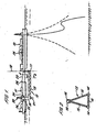
- a first floating vessel 10 which may be a production or storage vessel moored to the seabed by any conventional and appropriate means.
- the transfer apparatus 12 is shown in use, connecting the two vessels 10,11.
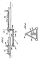
- the transfer apparatus 12 consists of a submerged rigid arm 13, typically of space frame type construction. As shown in Figure 2 , the arm 13 may be formed of three longitudinal members 14 arranged in a triangular form and joined by a number of transverse bracing members 15.
- Piping 16 for example rigid steel piping, is attached to the arm and carries the fluid being transferred.
- the piping 16 may be located inside one or more of the longitudinal members 14 and insulation (not shown) may also be provided. This construction protects the piping 16 but also allows the possibility of inspection of the piping 16.
- attachment means 17 is provided for attaching the arm 13 to the first vessel 10, preferably at the stern.
- the attachment means 17 may be constructed in any convenient form which includes articulations allowing the arm 13 to pivot about at least two axes relative to the vessel 10, preferably the vertical axis 18 and the horizontal axis extending perpendicularly into and out of the plane of the paper.
- the attachment means 17 projects downwardly from the vessel 10 and is dimensioned such that the arm 13 is located underwater at a depth greater than the maximum draught of both the first and second vessels 10, 11.
- float means 19 is provided which extends upwardly from the arm 13 and projects above the water surface.
- a loading device 20 which is preferably a cryogenic loading device of known form, is located on the top of the float means 19. Articulations may be provided to allow the loading device 20 to pivot relative to the float means 19.
- the loading device 20 is connected to the piping 16 and is connectable to the second vessel 11 to allow transfer of fluid from the piping 16 to the vessel 11.
- the loading device 20 is configured to allow fluid pumped from the first vessel 10 to be readily returned to it, for example in the case of an emergency disconnect from the second vessel 11.
- the piping 16 is preferably provided with flexible connections such as swivel joints or flexible hoses where necessary to allow it to bridge the various points of articulation in the apparatus 12.
- the rigid arm 13 is preferably designed to be of a suitable length such that in use, when the proximal end is attached to the stern of the first vessel 10, its distal end will be adjacent a midship portion of the second vessel 11.
- one or more thrusters 21 is located at the lower end of the float member 19.
- the or each thruster 21 is powered and controlled from the first vessel 10, for the purpose described further below.
- the thrusters 21 are used to rotate the arm 13 about the vertical axis 18, for example to rotate it anti-clockwise if viewed from above in Figure 1 , so that it does not obstruct the area around the stern of the first vessel 10.
- the second vessel 11 can then be manoeuvred into position adjacent the first vessel 10 as shown in Figure 1 .
- the first and second vessels 10, 11 may now be moored stern to bow by a line 22, for example an elastic line, as shown in Figures 1 and 3 .
- the thrusters 21 are operated again to rotate the arm 13 in the opposite direction, (clockwise when viewed from above in Figure 1 ) to bring the float means 19 and loading device 20 adjacent preferably the midship portion of the second vessel 11.
- the rigid arm 13 is moored to the vessel 11 by any suitable mooring means, such as mooring lines 23 shown schematically in Figure 1 .
- the loading device 20 is connected to the appropriate fluid receiving apparatus on board the vessel 11 so that fluid from the piping 16 can be transferred to the second vessel 11.
- the mooring means 23 is disconnected from the vessel 11.
- the thrusters 21 are then operated to rotate the arm 13 away from the vessel 11, allowing it to leave the area unobstructed.
- the thrusters 21 are also employed to maintain the rigid arm 13 in a substantially fixed position relative to the vessel 11, to ensure that no unacceptable loads are imposed on the loading device 20 and various interconnections between the piping 16 and the vessel 11.
- a position monitoring device 24 is mounted on a point on the transfer apparatus 12, for example on the float means 19, to monitor continuously the separation of that point from the hull of the vessel 11.
- the position monitoring device 24 may act by electronic or visual means.
- a control system 25 preferably located on the first vessel 10 receives information from the position monitoring device 24. If the transfer apparatus 12 and the vessel 11 move towards or away from one another so that their separation is no longer within an acceptable range, the control system 25 responds by operating the thrusters 21 to move the transfer apparatus 12 in an appropriate direction so as to restore the transfer apparatus 12 and the vessel 11 to within an acceptable separation range. In this way, any relative movement due to the action of wind and waves can be accommodated to avoid the risk of damaging the transfer apparatus 12 and/or the vessel 11.
- the apparatus also comprises means 26 to monitor whether the mooring means 23 is actually attached to the vessel 11 and/or whether the line 22 is attached to the vessel 11. If the mooring means 23 and/or line 22 become accidentally detached from the vessel 11, the control system 25 operates to automatically disconnect the loading device 20 from the vessel 11, to avoid any damage to the loading device 20 which might occur if the separation of the vessel 11 and the transfer apparatus 12 changes significantly due to detachment of the mooring means 22,23.
- control system 25 operates in this way to disconnect the loading device 20 from the vessel 11, it also operates the thrusters 21 to move the rigid arm 13 well away from the vessel 11, to avoid the danger of collision.
- the transfer apparatus 12 When the transfer apparatus 12 is not being used, it may have its distal end secured to the first vessel 10. For example, if the transfer apparatus 12 is attached to the stern of the vessel 10, it can be pivoted back round so that its distal end can be secured to the vessel 10 towards the bow region as shown in dotted lines in Figure 3 . In this way the transfer apparatus 12 is able to withstand extreme weather conditions which may exceed its design parameters. It also allows inspection, repair and maintenance to be carried out more easily.
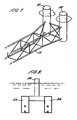
- the fixed structure may comprise a base 27 mounted on the seabed from which a column 28 rises to above the surface of the water.
- the base 27 may be a well-head, or connected by a seabed pipeline to a well-head or onshore plant.
- the arm 13 is attached to the column 28 by articulated attachment means 17 and the vessel 11 may be moored to the column 28 by a line 22.
- the other features are the same as in the first embodiment.
- FIG. 5 An embodiment of transfer apparatus 12 of the present invention is shown in Figure 5 for transfer between two floating vessels 10, 11. This is generally similar to the apparatus of Figure 1 . However, in this case, at its first, proximal end the arm 13 includes an upward projection 13a which extends up above the waterline and is connected to the first vessel 10 by attachment means 17.
- the attachment means 17 may be constructed in any convenient form which includes articulations allowing the arm 13 to pivot about three axes relative to the vessel 10, preferably the vertical axis 18, a horizontal axis extending into and out of the plane of the paper and a horizontal axis parallel with the plane of the paper.
- the upward projection 13a and the attachment means 17 are sized such that the horizontal portion of the arm 13 is located underwater at a depth greater than the maximum draught of both the first and second vessels 10, 11. This construction allows easier access to the attachment means 17 for inspection, maintenance and repair.
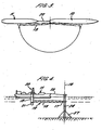
- the float means 19 at the distal end of the arm 13 preferably incorporates at least one and preferably two buoyancy devices 31, 32 as shown in Figure 7 .
- the buoyancy devices 31, 32 are substantially cylindrical members which are mutually spaced and project both above and below the waterline.
- the piping 16 is located inside a conduit or tunnel 30 which extends the length of the arm 13, for example within the space frame construction, as seen in Figure 6 .
- the tunnel 30 has an opening above the waterline at the proximal end of the transfer apparatus 12 and extends continuously to another opening above the waterline at the distal end.
- the tunnel 3G and openings are designed to permit personnel entry and movement therealong. In this way the entire length of pipeline 16 is accessible in a substantially dry environment for inspection, repair and maintenance, avoiding the need for divers.
- the piping 16 is preferably provided with flexible connections such as swivel joints or flexible hoses where necessary to allow it to bridge the various points of articulation in the apparatus 12.
Landscapes
- Engineering & Computer Science (AREA)
- Mechanical Engineering (AREA)
- Chemical & Material Sciences (AREA)
- Combustion & Propulsion (AREA)
- Ocean & Marine Engineering (AREA)
- Health & Medical Sciences (AREA)
- Public Health (AREA)
- Loading And Unloading Of Fuel Tanks Or Ships (AREA)
- Filling Or Discharging Of Gas Storage Vessels (AREA)
- Manipulator (AREA)
Claims (20)
- Vorrichtung (12) zum Umlagern eines Fluids zwischen einem ersten und einem zweiten schwimmenden Schiff (10, 11), die versehen ist mit einem starren Unterwasser-Umlagerungsausleger (13), wenigstens einer Fluidpipeline (16) zum Umlagern von Fluid zwischen dem ersten und dem zweiten Schiff (10, 11), wobei die Pipeline (16) in einem am Ausleger (13) montierten Kanal (30) angeordnet ist, Mittel (17) zum Befestigen eines ersten Endes des Auslegers (13) am ersten Schiff (10), um somit dem Ausleger (13) zu erlauben, um drei Achsen zu schwenken, und einem Lademittel (20), das am zweiten Ende des Auslegers (13) angeordnet ist und am zweiten Schiff (11) anbringbar ist, um Fluid von der Fluidpipeline (16) zum zweiten Schiff (11) umzulagern; dadurch gekennzeichnet, dass der Kanal (30) an jedem Ende eine Öffnung aufweist, die sich über der Wasserlinie befindet, und dass sich das Mittel (17) zum Befestigen eines ersten Endes des Auslegers (13) am ersten Schiff (10) im Gebrauch an einer Position über der Wasserlinie befindet.
- Vorrichtung nach Anspruch 1, wobei der starre Ausleger (13) eine Raumrahmenkonstruktion ist, die mehrere Longitudinalelemente (14) aufweist, die mittels mehrerer transversaler Stützelemente (15) verbunden sind.
- Vorrichtung nach Anspruch 1 oder Anspruch 2, wobei um die Fluidpipeline eine Isolierung vorgesehen ist.
- Vorrichtung nach irgendeinem der vorangehenden Ansprüche, wobei der Kanal (30) so konfiguriert ist, dass er einen Zugang in sein Inneres zur Inspektion und Wartung der Fluidpipeline (16) gestattet.
- Vorrichtung (12) nach irgendeinem der vorangehenden Ansprüche, wobei die Vorrichtung versehen ist mit Schubkraftmitteln (21), die so betreibbar sind, dass sie den starren Ausleger (13) im Gebrauch relativ zum ersten Schiff (10) um eine im Wesentlichen vertikale Achse drehen, mit Positions-überwachungsmitteln (24) zum Überwachen der Entfernung eines Punktes auf dem Ausleger (13) vom zweiten Schiff (11), und mit einem Steuersystem (25), das so betreibbar ist, dass es die Schubkraftmittel (21) betätigt, wenn die Entfernung außerhalb eines vorgegebenen Bereiches liegt, um somit den Ausleger (13) relativ zum zweiten Schiff (11) zu bewegen und dadurch die Entfernung in den vorgegebenen Bereich zurückzuführen.
- Vorrichtung (12) nach irgendeinem der vorangehenden Ansprüche, die ferner ein Festmachmittel (23) zum Festmachen der Vorrichtung (12) am zweiten Schiff (11), Mittel (26) zum Überwachen, ob das Festmachmittel (23) am zweiten Schiff (11) befestigt ist, und Mittel zum automatischen Trennen des Lademittels (20) vom zweiten Schiff (11), wenn das Festmachmittel (23) vom zweiten Schiff (11) gelöst wird, umfasst.
- Vorrichtung (12) nach irgendeinem der vorangehenden Ansprüche, die ferner ein Festmachmittel zum Festmachen des zweiten Schiffes (11) am ersten Schiff (10), Mittel zum Überwachen, ob das Festmachmittel am zweiten Schiff (11) befestigt ist, und Mittel zum automatischen Trennen der Ladevorrichtung (20) vom zweiten Schiff (11), wenn das Festmachmittel vom zweiten Schiff (11) gelöst wird, umfasst.
- Vorrichtung (12) nach Anspruch 6 oder Anspruch 7, wobei dann, wenn das Lademittel (20) automatisch vom zweiten Schiff (11) getrennt wird, das Steuermittel (25) so betreibbar ist, dass es das Schubkraftmittel (21) betätigt, um den Ausleger (13) vom zweiten Schiff (11) wegzubewegen.
- Vorrichtung (12) nach irgendeinem der vorangehenden Ansprüche, wobei die Fluidpipeline (16) mit flexiblen Verbindungen versehen ist, die ihr erlauben, die Gelenkpunkte in der Vorrichtung (12) zu überbrücken.
- Vorrichtung (12) nach irgendeinem der vorangehenden Ansprüche, wobei das Lademittel (20) eine Kühlladevorrichtung umfasst.
- Vorrichtung (12) nach irgendeinem der vorangehenden Ansprüche, die ferner ein Schwimmkörpermittel (19) am zweiten Ende des Auslegers (13) umfasst, das wenigstens eine Auftriebsvorrichtung umfasst, die sich im Gebrauch sowohl oberhalb als auch unterhalb der Wasserlinie erstreckt.
- Vorrichtung nach Anspruch 11, wobei das Schwimmkörpermittel (19) zwei gegenseitig beabstandete Auftriebsvorrichtungen (31, 32) umfasst, die sich im Gebrauch jeweils sowohl oberhalb als auch unterhalb der Wasserlinie erstrecken.
- Vorrichtung (12) nach Anspruch 11, wobei das Schwimmkörpermittel (19) zwei gegenseitig beabstandete Unterwasser-Auftriebsvorrichtungen (33, 34), die an ihren oberen Enden miteinander verbunden sind, sowie eine einzelne Auftriebsvorrichtung (35) umfasst, die sich im Gebrauch oberhalb der Wasserlinie erstreckt.
- Vorrichtung (12) nach Anspruch 3, wobei der starre Ausleger (13) eine Raumrahmenkonstruktion ist, die mehrere Longitudinalelemente (14) aufweist, die mittels mehrerer transversaler Stützelemente (15) verbunden sind, wobei ein Umfangsrahmen gebildet wird, in dem der Kanal (30) angeordnet ist.
- Vorrichtung (12) nach irgendeinem der vorangehenden Ansprüche, die ferner ein Fendersystem am zweiten Ende des starren Auslegers (13) umfasst.
- Vorrichtung (12) nach irgendeinem der vorangehenden Ansprüche, wobei im Gebrauch der starre Unterwasserausleger (13)im Wesentlichen horizontal verläuft.
- Verfahren zum Umlagern eines Fluids von einem ersten Schiff (10) zu einem zweiten Schiff (11) unter Verwendung der Vorrichtung (12) nach Anspruch 5, die Schritte umfassend:Betätigen des Schubkraftmittels (21), um den Ausleger (13) in einer ersten Richtung um eine durch das Befestigungsmittel (17) definierte Achse bezüglich des ersten Schiffes (10) zu schwenken; Bewegen des zweiten Schiffes (11) in eine Position in der Nähe des ersten Schiffes (10); Betätigen des Schubkraftmittels (21), um den Ausleger in einer zweiten Richtung entgegengesetzt zur ersten Richtung zu schwenken, um somit das Lademittel (20) neben das zweite Schiff (11) zu bringen; Verbinden des Lademittels (20) mit dem zweiten Schiff (11) und Umlagern des Fluids von der Fluidpipeline (16) zum zweiten Schiff (11); Trennen des Lademittels (20) vom zweiten Schiff (11) und Betätigen des Schubkraftmittels (21), um den Ausleger (13) in der ersten Richtung vom zweiten Schiff (11) wegzuschwenken; wobei das Verfahren dann, wenn die Ladevorrichtung (20) mit dem zweiten Schiff (11) verbunden ist, das Überwachen der Entfernung zwischen einem Punkt am Ausleger (13) und dem zweiten Schiff (11), sowie das Betätigen des Schubkraftmittels (21), wenn die Entfernung außerhalb eines vorgegebenen Bereichs liegt, um somit den Ausleger (13) relativ zum zweiten Schiff (11) zu bewegen und die Entfernung in den vorgegebenen Bereich zurückzuführen, umfasst.
- Verfahren nach Anspruch 17, das ferner den Schritt des Überwachens, ob das Festmachmittel (23) am Ausleger (13) am zweiten Schiff (11) befestigt ist, und, im Fall des Lösens, das automatische Trennen der Ladevorrichtung (20) vom zweiten Schiff (11) umfasst.
- Verfahren nach Anspruch 17 oder Anspruch 18, das ferner den Schritt des Überwachens, ob das Festmachmittel am ersten Schiff (10) am zweiten Schiff (11) befestigt ist, und, im Fall des Lösens, das automatische Trennen der Ladevorrichtung (20) vom zweiten Schiff (11) umfasst.
- Verfahren nach Anspruch 18 oder Anspruch 19, wobei im Fall der automatischen Trennung der Ladevorrichtung (20) vom zweiten Schiff (11) das Schubkraftmittel (20) betätigt wird, um den Ausleger (13) in der ersten Richtung vom zweiten Schiff (11) wegzubewegen.
Applications Claiming Priority (5)
| Application Number | Priority Date | Filing Date | Title |
|---|---|---|---|
| GB0124570A GB2382809B (en) | 2001-10-12 | 2001-10-12 | Fluid transfer system with thrusters and position monitoring |
| GB0124570 | 2001-10-12 | ||
| GB0206353A GB2380724B (en) | 2001-10-12 | 2002-03-18 | Offshore fluid transfer system |
| GB0206353 | 2002-03-18 | ||
| EP02781462A EP1434711B1 (de) | 2001-10-12 | 2002-10-10 | Offshore-flüssigkeitstransferierungssystem |
Related Parent Applications (1)
| Application Number | Title | Priority Date | Filing Date |
|---|---|---|---|
| EP02781462A Division EP1434711B1 (de) | 2001-10-12 | 2002-10-10 | Offshore-flüssigkeitstransferierungssystem |
Publications (3)
| Publication Number | Publication Date |
|---|---|
| EP1557352A2 EP1557352A2 (de) | 2005-07-27 |
| EP1557352A3 EP1557352A3 (de) | 2005-11-16 |
| EP1557352B1 true EP1557352B1 (de) | 2008-07-23 |
Family
ID=9923746
Family Applications (1)
| Application Number | Title | Priority Date | Filing Date |
|---|---|---|---|
| EP05008023A Expired - Lifetime EP1557352B1 (de) | 2001-10-12 | 2002-10-10 | System zur Übergabe von Flüssigkeiten auf See |
Country Status (2)
| Country | Link |
|---|---|
| EP (1) | EP1557352B1 (de) |
| GB (2) | GB2382809B (de) |
Families Citing this family (1)
| Publication number | Priority date | Publication date | Assignee | Title |
|---|---|---|---|---|
| RU2381134C2 (ru) | 2004-10-15 | 2010-02-10 | Эксонмобил Апстрим Рисерч Компани | Подводная система перекачки криогенной текучей среды |
Family Cites Families (13)
| Publication number | Priority date | Publication date | Assignee | Title |
|---|---|---|---|---|
| NL6414787A (de) * | 1964-12-18 | 1966-06-20 | ||
| US3556148A (en) | 1968-07-11 | 1971-01-19 | Fmc Corp | Double counterbalanced marine loading arm |
| FR2133307A5 (de) * | 1971-04-16 | 1972-11-24 | Elf Entr Rech Activit | |
| US3957291A (en) * | 1975-01-10 | 1976-05-18 | The Offshore Company | Ball joint assembly with internal passages |
| GB2014578B (en) * | 1978-02-09 | 1982-08-04 | Cpc International Inc | Process for producing multi sugar syrups plus crystalline dextrose from starch |
| DE2823096C2 (de) * | 1978-05-26 | 1982-06-24 | Licentia Patent-Verwaltungs-Gmbh, 6000 Frankfurt | Anordnung zur Abstandsmessung zwischen zwei Schwimmkörpern |
| FR2448496A1 (fr) * | 1979-02-12 | 1980-09-05 | Fmc Europe | Bras articule de chargement et de dechargement de produits, en particulier de produits fluides |
| EP0029768B1 (de) * | 1979-11-12 | 1986-04-23 | FMC EUROPE S.A. Société anonyme dite: | Verfahren und Anlage zum Überwachen und Steuern eines gelenkigen Fluidumübertragungsarmes, der dazu bestimmt ist, ein Schiff mit einer Plattform im Meer zu verbinden |
| IT1208125B (it) * | 1983-03-14 | 1989-06-06 | Tecnomare Spa | Sistema di attracco di navicisterna a struttura fissa. |
| US4758970A (en) * | 1984-08-08 | 1988-07-19 | Emco Wheaton, Inc. | Marine loading arm monitoring system |
| US4602586A (en) * | 1984-12-24 | 1986-07-29 | Exxon Production Research Co. | Motion decoupling mechanism for fluid swivel stack |
| GB2328197B (en) * | 1997-08-12 | 1999-08-11 | Bluewater Terminal Systems Nv | Fluid transfer system |
| GB2388355B (en) * | 2000-12-01 | 2004-01-28 | Billy-Jay Smart | Vessel navigation and docking system and method |
-
2001
- 2001-10-12 GB GB0124570A patent/GB2382809B/en not_active Expired - Fee Related
-
2002
- 2002-03-18 GB GB0206353A patent/GB2380724B/en not_active Expired - Fee Related
- 2002-10-10 EP EP05008023A patent/EP1557352B1/de not_active Expired - Lifetime
Also Published As
| Publication number | Publication date |
|---|---|
| GB2380724B (en) | 2004-11-03 |
| GB0206353D0 (en) | 2002-05-01 |
| GB2382809B (en) | 2004-11-03 |
| EP1557352A2 (de) | 2005-07-27 |
| GB2380724A (en) | 2003-04-16 |
| GB2382809A (en) | 2003-06-11 |
| GB0124570D0 (en) | 2001-12-05 |
| EP1557352A3 (de) | 2005-11-16 |
Similar Documents
| Publication | Publication Date | Title |
|---|---|---|
| EP1308384B1 (de) | Übergabesystem für Kohlenwasserstoffe | |
| EP2025591B1 (de) | Flüssigerdgas-Entladesystem bei Seitenwind | |
| US7690434B2 (en) | Offshore vessel mooring and riser inboarding system | |
| AU2002325936A1 (en) | Hydrocarbon fluid transfer system | |
| CN102448810B (zh) | 离岸结构和系泊装置 | |
| EP1434711B1 (de) | Offshore-flüssigkeitstransferierungssystem | |
| EP2240362B1 (de) | System zur Kohlenwasserstoffübertragung mit einem schwenkbaren Ausleger | |
| AU2002348952A1 (en) | Offshore fluid transfer system | |
| GB2328196A (en) | Fluid transfer system | |
| EP1557352B1 (de) | System zur Übergabe von Flüssigkeiten auf See | |
| CN210734442U (zh) | 用于传输流体或电力的浮式的传输结构和传输系统 | |
| US7182660B2 (en) | Offshore fluid transfer system | |
| EP1389580A1 (de) | Flüssigkeits- Transferierungszwischenstelle | |
| CN110510072A (zh) | 用于传输流体或电力的浮式的传输结构、传输系统及传输方法 | |
| GB2383317A (en) | Submerged friction mooring device |
Legal Events
| Date | Code | Title | Description |
|---|---|---|---|
| PUAI | Public reference made under article 153(3) epc to a published international application that has entered the european phase |
Free format text: ORIGINAL CODE: 0009012 |
|
| 17P | Request for examination filed |
Effective date: 20050413 |
|
| AC | Divisional application: reference to earlier application |
Ref document number: 1434711 Country of ref document: EP Kind code of ref document: P |
|
| AK | Designated contracting states |
Kind code of ref document: A2 Designated state(s): CH FR GB IT LI NL |
|
| PUAL | Search report despatched |
Free format text: ORIGINAL CODE: 0009013 |
|
| AK | Designated contracting states |
Kind code of ref document: A3 Designated state(s): CH FR GB IT LI NL |
|
| RIC1 | Information provided on ipc code assigned before grant |
Ipc: 7B 63B 27/34 A Ipc: 7B 63B 43/18 B |
|
| AKX | Designation fees paid |
Designated state(s): CH FR GB IT LI NL |
|
| 17Q | First examination report despatched |
Effective date: 20060907 |
|
| GRAP | Despatch of communication of intention to grant a patent |
Free format text: ORIGINAL CODE: EPIDOSNIGR1 |
|
| GRAS | Grant fee paid |
Free format text: ORIGINAL CODE: EPIDOSNIGR3 |
|
| GRAA | (expected) grant |
Free format text: ORIGINAL CODE: 0009210 |
|
| AC | Divisional application: reference to earlier application |
Ref document number: 1434711 Country of ref document: EP Kind code of ref document: P |
|
| AK | Designated contracting states |
Kind code of ref document: B1 Designated state(s): CH FR GB IT LI NL |
|
| REG | Reference to a national code |
Ref country code: GB Ref legal event code: FG4D |
|
| REG | Reference to a national code |
Ref country code: CH Ref legal event code: EP |
|
| REG | Reference to a national code |
Ref country code: CH Ref legal event code: NV Representative=s name: KIRKER & CIE S.A. |
|
| PLBE | No opposition filed within time limit |
Free format text: ORIGINAL CODE: 0009261 |
|
| STAA | Information on the status of an ep patent application or granted ep patent |
Free format text: STATUS: NO OPPOSITION FILED WITHIN TIME LIMIT |
|
| 26N | No opposition filed |
Effective date: 20090424 |
|
| PGFP | Annual fee paid to national office [announced via postgrant information from national office to epo] |
Ref country code: FR Payment date: 20121205 Year of fee payment: 11 Ref country code: CH Payment date: 20121017 Year of fee payment: 11 |
|
| PGFP | Annual fee paid to national office [announced via postgrant information from national office to epo] |
Ref country code: GB Payment date: 20121025 Year of fee payment: 11 Ref country code: IT Payment date: 20121025 Year of fee payment: 11 |
|
| PGFP | Annual fee paid to national office [announced via postgrant information from national office to epo] |
Ref country code: NL Payment date: 20121024 Year of fee payment: 11 |
|
| REG | Reference to a national code |
Ref country code: NL Ref legal event code: V1 Effective date: 20140501 |
|
| REG | Reference to a national code |
Ref country code: CH Ref legal event code: PL |
|
| GBPC | Gb: european patent ceased through non-payment of renewal fee |
Effective date: 20131010 |
|
| PG25 | Lapsed in a contracting state [announced via postgrant information from national office to epo] |
Ref country code: CH Free format text: LAPSE BECAUSE OF NON-PAYMENT OF DUE FEES Effective date: 20131031 Ref country code: LI Free format text: LAPSE BECAUSE OF NON-PAYMENT OF DUE FEES Effective date: 20131031 Ref country code: GB Free format text: LAPSE BECAUSE OF NON-PAYMENT OF DUE FEES Effective date: 20131010 |
|
| REG | Reference to a national code |
Ref country code: FR Ref legal event code: ST Effective date: 20140630 |
|
| PG25 | Lapsed in a contracting state [announced via postgrant information from national office to epo] |
Ref country code: FR Free format text: LAPSE BECAUSE OF NON-PAYMENT OF DUE FEES Effective date: 20131031 Ref country code: IT Free format text: LAPSE BECAUSE OF NON-PAYMENT OF DUE FEES Effective date: 20131010 Ref country code: NL Free format text: LAPSE BECAUSE OF NON-PAYMENT OF DUE FEES Effective date: 20140501 |