EP1557191A2 - A safety needle assembly - Google Patents
A safety needle assembly Download PDFInfo
- Publication number
- EP1557191A2 EP1557191A2 EP05006983A EP05006983A EP1557191A2 EP 1557191 A2 EP1557191 A2 EP 1557191A2 EP 05006983 A EP05006983 A EP 05006983A EP 05006983 A EP05006983 A EP 05006983A EP 1557191 A2 EP1557191 A2 EP 1557191A2
- Authority
- EP
- European Patent Office
- Prior art keywords
- shield
- housing
- needle assembly
- safety needle
- locking protrusion
- Prior art date
- Legal status (The legal status is an assumption and is not a legal conclusion. Google has not performed a legal analysis and makes no representation as to the accuracy of the status listed.)
- Granted
Links
Images



Classifications
-
- A—HUMAN NECESSITIES
- A61—MEDICAL OR VETERINARY SCIENCE; HYGIENE
- A61M—DEVICES FOR INTRODUCING MEDIA INTO, OR ONTO, THE BODY; DEVICES FOR TRANSDUCING BODY MEDIA OR FOR TAKING MEDIA FROM THE BODY; DEVICES FOR PRODUCING OR ENDING SLEEP OR STUPOR
- A61M5/00—Devices for bringing media into the body in a subcutaneous, intra-vascular or intramuscular way; Accessories therefor, e.g. filling or cleaning devices, arm rests
- A61M5/178—Syringes
- A61M5/31—Details
- A61M5/32—Needles; Details of needles pertaining to their connection with syringe or hub; Accessories for bringing the needle into, or holding the needle on, the body; Devices for protection of needles
- A61M5/3205—Apparatus for removing or disposing of used needles or syringes, e.g. containers; Means for protection against accidental injuries from used needles
- A61M5/321—Means for protection against accidental injuries by used needles
- A61M5/3243—Means for protection against accidental injuries by used needles being axially-extensible, e.g. protective sleeves coaxially slidable on the syringe barrel
- A61M5/3245—Constructional features thereof, e.g. to improve manipulation or functioning
-
- A—HUMAN NECESSITIES
- A61—MEDICAL OR VETERINARY SCIENCE; HYGIENE
- A61M—DEVICES FOR INTRODUCING MEDIA INTO, OR ONTO, THE BODY; DEVICES FOR TRANSDUCING BODY MEDIA OR FOR TAKING MEDIA FROM THE BODY; DEVICES FOR PRODUCING OR ENDING SLEEP OR STUPOR
- A61M5/00—Devices for bringing media into the body in a subcutaneous, intra-vascular or intramuscular way; Accessories therefor, e.g. filling or cleaning devices, arm rests
- A61M5/178—Syringes
- A61M5/31—Details
- A61M5/32—Needles; Details of needles pertaining to their connection with syringe or hub; Accessories for bringing the needle into, or holding the needle on, the body; Devices for protection of needles
-
- A—HUMAN NECESSITIES
- A61—MEDICAL OR VETERINARY SCIENCE; HYGIENE
- A61M—DEVICES FOR INTRODUCING MEDIA INTO, OR ONTO, THE BODY; DEVICES FOR TRANSDUCING BODY MEDIA OR FOR TAKING MEDIA FROM THE BODY; DEVICES FOR PRODUCING OR ENDING SLEEP OR STUPOR
- A61M5/00—Devices for bringing media into the body in a subcutaneous, intra-vascular or intramuscular way; Accessories therefor, e.g. filling or cleaning devices, arm rests
- A61M5/178—Syringes
- A61M5/31—Details
- A61M5/32—Needles; Details of needles pertaining to their connection with syringe or hub; Accessories for bringing the needle into, or holding the needle on, the body; Devices for protection of needles
- A61M5/3205—Apparatus for removing or disposing of used needles or syringes, e.g. containers; Means for protection against accidental injuries from used needles
- A61M5/321—Means for protection against accidental injuries by used needles
- A61M5/3243—Means for protection against accidental injuries by used needles being axially-extensible, e.g. protective sleeves coaxially slidable on the syringe barrel
- A61M5/326—Fully automatic sleeve extension, i.e. in which triggering of the sleeve does not require a deliberate action by the user
-
- A—HUMAN NECESSITIES
- A61—MEDICAL OR VETERINARY SCIENCE; HYGIENE
- A61M—DEVICES FOR INTRODUCING MEDIA INTO, OR ONTO, THE BODY; DEVICES FOR TRANSDUCING BODY MEDIA OR FOR TAKING MEDIA FROM THE BODY; DEVICES FOR PRODUCING OR ENDING SLEEP OR STUPOR
- A61M5/00—Devices for bringing media into the body in a subcutaneous, intra-vascular or intramuscular way; Accessories therefor, e.g. filling or cleaning devices, arm rests
- A61M5/178—Syringes
-
- A—HUMAN NECESSITIES
- A61—MEDICAL OR VETERINARY SCIENCE; HYGIENE
- A61M—DEVICES FOR INTRODUCING MEDIA INTO, OR ONTO, THE BODY; DEVICES FOR TRANSDUCING BODY MEDIA OR FOR TAKING MEDIA FROM THE BODY; DEVICES FOR PRODUCING OR ENDING SLEEP OR STUPOR
- A61M5/00—Devices for bringing media into the body in a subcutaneous, intra-vascular or intramuscular way; Accessories therefor, e.g. filling or cleaning devices, arm rests
- A61M5/178—Syringes
- A61M5/31—Details
- A61M5/32—Needles; Details of needles pertaining to their connection with syringe or hub; Accessories for bringing the needle into, or holding the needle on, the body; Devices for protection of needles
- A61M5/34—Constructions for connecting the needle, e.g. to syringe nozzle or needle hub
-
- B—PERFORMING OPERATIONS; TRANSPORTING
- B42—BOOKBINDING; ALBUMS; FILES; SPECIAL PRINTED MATTER
- B42D—BOOKS; BOOK COVERS; LOOSE LEAVES; PRINTED MATTER CHARACTERISED BY IDENTIFICATION OR SECURITY FEATURES; PRINTED MATTER OF SPECIAL FORMAT OR STYLE NOT OTHERWISE PROVIDED FOR; DEVICES FOR USE THEREWITH AND NOT OTHERWISE PROVIDED FOR; MOVABLE-STRIP WRITING OR READING APPARATUS
- B42D15/00—Printed matter of special format or style not otherwise provided for
-
- G—PHYSICS
- G09—EDUCATION; CRYPTOGRAPHY; DISPLAY; ADVERTISING; SEALS
- G09F—DISPLAYING; ADVERTISING; SIGNS; LABELS OR NAME-PLATES; SEALS
- G09F1/00—Cardboard or like show-cards of foldable or flexible material
- G09F1/04—Folded cards
-
- A—HUMAN NECESSITIES
- A61—MEDICAL OR VETERINARY SCIENCE; HYGIENE
- A61M—DEVICES FOR INTRODUCING MEDIA INTO, OR ONTO, THE BODY; DEVICES FOR TRANSDUCING BODY MEDIA OR FOR TAKING MEDIA FROM THE BODY; DEVICES FOR PRODUCING OR ENDING SLEEP OR STUPOR
- A61M5/00—Devices for bringing media into the body in a subcutaneous, intra-vascular or intramuscular way; Accessories therefor, e.g. filling or cleaning devices, arm rests
- A61M5/178—Syringes
- A61M5/31—Details
- A61M5/32—Needles; Details of needles pertaining to their connection with syringe or hub; Accessories for bringing the needle into, or holding the needle on, the body; Devices for protection of needles
- A61M5/3205—Apparatus for removing or disposing of used needles or syringes, e.g. containers; Means for protection against accidental injuries from used needles
- A61M5/321—Means for protection against accidental injuries by used needles
- A61M5/3243—Means for protection against accidental injuries by used needles being axially-extensible, e.g. protective sleeves coaxially slidable on the syringe barrel
- A61M5/3245—Constructional features thereof, e.g. to improve manipulation or functioning
- A61M2005/3247—Means to impede repositioning of protection sleeve from needle covering to needle uncovering position
-
- A—HUMAN NECESSITIES
- A61—MEDICAL OR VETERINARY SCIENCE; HYGIENE
- A61M—DEVICES FOR INTRODUCING MEDIA INTO, OR ONTO, THE BODY; DEVICES FOR TRANSDUCING BODY MEDIA OR FOR TAKING MEDIA FROM THE BODY; DEVICES FOR PRODUCING OR ENDING SLEEP OR STUPOR
- A61M5/00—Devices for bringing media into the body in a subcutaneous, intra-vascular or intramuscular way; Accessories therefor, e.g. filling or cleaning devices, arm rests
- A61M5/178—Syringes
- A61M5/31—Details
- A61M5/32—Needles; Details of needles pertaining to their connection with syringe or hub; Accessories for bringing the needle into, or holding the needle on, the body; Devices for protection of needles
- A61M5/3205—Apparatus for removing or disposing of used needles or syringes, e.g. containers; Means for protection against accidental injuries from used needles
- A61M5/321—Means for protection against accidental injuries by used needles
- A61M5/3243—Means for protection against accidental injuries by used needles being axially-extensible, e.g. protective sleeves coaxially slidable on the syringe barrel
- A61M5/326—Fully automatic sleeve extension, i.e. in which triggering of the sleeve does not require a deliberate action by the user
- A61M2005/3267—Biased sleeves where the needle is uncovered by insertion of the needle into a patient's body
-
- A—HUMAN NECESSITIES
- A61—MEDICAL OR VETERINARY SCIENCE; HYGIENE
- A61M—DEVICES FOR INTRODUCING MEDIA INTO, OR ONTO, THE BODY; DEVICES FOR TRANSDUCING BODY MEDIA OR FOR TAKING MEDIA FROM THE BODY; DEVICES FOR PRODUCING OR ENDING SLEEP OR STUPOR
- A61M2205/00—General characteristics of the apparatus
- A61M2205/58—Means for facilitating use, e.g. by people with impaired vision
- A61M2205/583—Means for facilitating use, e.g. by people with impaired vision by visual feedback
- A61M2205/584—Means for facilitating use, e.g. by people with impaired vision by visual feedback having a color code
-
- A—HUMAN NECESSITIES
- A61—MEDICAL OR VETERINARY SCIENCE; HYGIENE
- A61M—DEVICES FOR INTRODUCING MEDIA INTO, OR ONTO, THE BODY; DEVICES FOR TRANSDUCING BODY MEDIA OR FOR TAKING MEDIA FROM THE BODY; DEVICES FOR PRODUCING OR ENDING SLEEP OR STUPOR
- A61M2205/00—General characteristics of the apparatus
- A61M2205/60—General characteristics of the apparatus with identification means
- A61M2205/6063—Optical identification systems
-
- A—HUMAN NECESSITIES
- A61—MEDICAL OR VETERINARY SCIENCE; HYGIENE
- A61M—DEVICES FOR INTRODUCING MEDIA INTO, OR ONTO, THE BODY; DEVICES FOR TRANSDUCING BODY MEDIA OR FOR TAKING MEDIA FROM THE BODY; DEVICES FOR PRODUCING OR ENDING SLEEP OR STUPOR
- A61M5/00—Devices for bringing media into the body in a subcutaneous, intra-vascular or intramuscular way; Accessories therefor, e.g. filling or cleaning devices, arm rests
- A61M5/002—Packages specially adapted therefor, e.g. packages for syringes or needles or kits for diabetics
-
- A—HUMAN NECESSITIES
- A61—MEDICAL OR VETERINARY SCIENCE; HYGIENE
- A61M—DEVICES FOR INTRODUCING MEDIA INTO, OR ONTO, THE BODY; DEVICES FOR TRANSDUCING BODY MEDIA OR FOR TAKING MEDIA FROM THE BODY; DEVICES FOR PRODUCING OR ENDING SLEEP OR STUPOR
- A61M5/00—Devices for bringing media into the body in a subcutaneous, intra-vascular or intramuscular way; Accessories therefor, e.g. filling or cleaning devices, arm rests
- A61M5/178—Syringes
- A61M5/31—Details
- A61M5/32—Needles; Details of needles pertaining to their connection with syringe or hub; Accessories for bringing the needle into, or holding the needle on, the body; Devices for protection of needles
- A61M5/3205—Apparatus for removing or disposing of used needles or syringes, e.g. containers; Means for protection against accidental injuries from used needles
- A61M5/321—Means for protection against accidental injuries by used needles
- A61M5/3243—Means for protection against accidental injuries by used needles being axially-extensible, e.g. protective sleeves coaxially slidable on the syringe barrel
- A61M5/3271—Means for protection against accidental injuries by used needles being axially-extensible, e.g. protective sleeves coaxially slidable on the syringe barrel with guiding tracks for controlled sliding of needle protective sleeve from needle exposing to needle covering position
Definitions
- the invention relates to a safety needle assembly, which reduces the risk of accidental needle-stick injuries, and especially a safety needle assembly where a needle cannula is mounted in a hub.
- Needle assemblies are commonly used to either inject substances into or extract substances out of human or animal bodies. Such needle assemblies are typically disposable and are discarded after only one use. The problem presented by the disposal of a needle assembly, and indeed, by any handling of the needle assembly, is the potential risk of being injured by the sharp end of the needle cannula. This is particular dangerous when following after the penetration of a patients skin since the needle cannula then may be contaminated and therefore capable of spreading diseases such as hepatitis and HIV.
- a great number of safety needle assemblies has been developed where the needle cannula is concealed by a telescopically movable shield during the injection.
- This safety needle comprises a hub with a centrally located needle cannula.
- a telescopically movable shield is provided on the outside surface of the hub.
- the shield is telescopically movable between a first position where it fully covers the needle cannula and a second position where a part or the needle cannula is left free to perform an injection.
- a cam element, rotatable mounted to the hub is provided with at least one cam, which cam is guided in cam curve provided in the inside surface of the shield.
- the shield is urged in the distal direction by a spring cocked between the hub and the shield.
- the cam curve is adapted to block the cam in a blocking position when the shield returns to the first position after an injection has been performed.
- the safety needle assembly disclosed in WO 01.76665 is however rather cumbersome and consist of a large number of parts that must be moulded and afterwards fitted together very precisely in order to obtain the correct movement of the cam follower.
- the locking element When the locking element is provided as a separate element located between the spring and the shield and moved simultaneously with the shield, the locking protrusion can be guided during the longitudinal movement of the locking member thereby eliminating the need for tracks or cams thus making it possible to construct the safety needle assembly from only three plastic part in addition to the hub.
- the length of the fins can be made such that once the shield has been activated and the needle cannula has emerged from the opening in the shield it will be impossible to abort the injection and keep the needle for later use.
- the shield When the locking protrusion engages the toothed ring of the shield, the shield can be moved all the way back in the proximal direction thereby uncovering the needle cannula.
- the guiding means for guiding the locking protrusion comprises only horizontally defined ribs and fins. This makes both the moulding of the parts and the assembly of the parts very simple.
- the housing By providing the housing with a window through which the locking protrusion can be viewed when it is in the arrested position, it is ensured that a user can visible inspect whether the safety needle assembly has been used before or not.
- the part of the shield and/or the locking element that are visible through the window when the safety needle assembly is in the unused condition can also be coloured in a colour indicating that the safety needle assembly is ready for use.
- the window can either be transparent or simply an opening in the sidewall of the housing.
- the term “moving simultaneous” which are used to describe the relationship between the movement of the shield and the locking element, does not necessary mean that the shield and the locking protrusion moves with the same speed.
- the relative speed of movement is defined by the various angled surfaces, and is therefore variable.
- the term “moving simultaneously” merely means that both the shield and the locking protrusion move at the same time.
- distal end is meant to refer to the end of the safety needle assembly inserted into the patient, whereas the term “proximal end” is meant to refer to the end connected to the injection device.
- Figure 1 shows a safety needle assembly comprising a housing 1 and a shield 2, the housing 1 is made up from a hub 3 and a body 4.
- the hub 3 and the body 4 is normally glued or welded together.
- the connecting surface 5 between the hub 3 and the body 4 is in the figures shown in a specific position, but could off cause be located as wanted.
- the hub 3 and the body 4 could even be moulded as one piece closed at the top surface 6 by a lit.
- the top surface 6 is provided with an opening 8 through which the shield 2 appears.
- the shield 2 is provided with a needle outlet 7 through which the needle cannula 30 can penetrate.
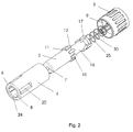
- the proximal end of the shield 2 is, as shown in figure 2, provided with eight outwardly projecting studs 10, which studs 10 has a planar fore front 11 and an angled back front 12.
- the housing 1 has a bottom surface 9 in the centre of which the needle cannula 30 is mounted.
- the needle cannula 30 can either be mounted such that a part of needle cannula 30 projects from the bottom surface 9 in the proximal direction, which is preferred for use with cartridges, or it can be mounted without this so called back needle, which is preferred for hypodermic syringes.
- Adjacent the bottom surface 9, at the proximal end of the housing 1, means are provided for mounting the safety needle assembly on to an injection device. These means would normally be a thread 35 such that the safety needle assembly can be screwed onto a pen syringe.
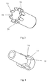
- Figure 3 shows the shield 2 seen from the proximal end.
- the eight studs 10 are separated from each other by eight equally sized spaces 26.
- the angular back front 12 of the studs 10 forms together with the shield 2 a toothed ring 13 where the centre of the studs 10 forms the tops and the shield 10 within the spaces 26 forms the valleys.
- the locking element 16 seen in figure 2 is on the proximal outside surface provided with four locking protrusions 17. These locking protrusions 17 have, as shown in figure 4, an angled fore front 18 and a planar back front 19.
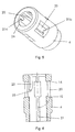
- the body 4 of the housing 1 is in figure 5 shown in perspective and in figure 6 in a sectional view.
- the body 4 is provided with four windows 20 and one longitudinal rib 21 for each window 20.
- the ribs 21 are provided on the inside surface of the body 4. These longitudinal ribs 21 extend through the entire length of the body 4 although divided into two parts (21a, 21 b) by the windows 20.
- the distal part of this rib 21 is moulded uniform with a collar 24 provided at the distal end of the body 4 and terminates in a planar surface 14 at the distal end of the window 20.
- the proximal part of the rib 21 terminates at the proximal end of the window in a blocking surface 15, the use of which will be explained later.
- fins 22 At the distal end of the body 4 there is provided four fins 22. These fins 22 is moulded uniform with the collar 24 at the distal end of the body 4, and has at the proximal end an angled surface 23 which terminates approximately in a position adjacent the middle of the windows 20.
- a spring 25 is cocked between the bottom surface 9 of the housing 1 and the locking element 16 urging the locking element 16 and the shield 2 in a distal direction.
- the planar forefront 11 on the studs 10 abuts the collar 24 such that the shield 2 is connected to the body 4 of the housing 1.
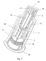
- FIG 7 The assembled safety needle assembly is shown in figure 7 and 8.
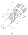
- Figure 8 illustrates the inside of the safety needle assembly with the body 4 cut away.
- the shield 2 is located such within the body 4 of the housing 1 that each rib 21 and each fin 22 is located in the space 26 between two studs 10.
- the upper part 21 a of the ribs 21 are however not shown in figure 8, since this upper rib 21 a is not entirely necessary.
- the locking element 16 is thereafter mounted such that the angular forefront 18 on each locking protrusion 17 abuts the angled back front 12 on four of the studs 10 of the shield 2, whereby the side surface of the locking protrusion 17 and the side surface of the studs 10 forms a straight line which line abuts the side surface of the fins 22 of the body 4 of the housing 1.
- the spring 25 is located around the needle cannula 30 and the body 4 and the hub 3 are sealed together, rendering the safety needle assembly ready for use.
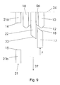
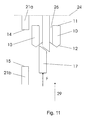
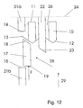
- the movement of the locking protrusion 17 is schematically shown in figure 9 - 12, showing the relative position of one of the locking protrusion 17 on the locking element 16, two of the studs 10 on the shield 2, one of the fins 22 on the inside surface of the body 4 of the housing 1 and one of the ribs 21 also located on the inside surface of the body 4 of the housing 1.
- Figure 9 illustrates the safety needle assembly in its initial position, as shown in figure 8, with the shield 2 in its distal position where the shield 2 covers the needle cannula 30.
- the shield 2 When the shield 2 is pressed towards the skin of a user, the shield 2 and with it the studs 10, are moved in a proximal direction as indicated with the arrow 27. This movement also moves the locking protrusion 17 on the locking element 16 in the proximal direction against the force F of the spring 25.
- the angled fore front 18 of the locking protrusions 17 will slide along the angled back front 12 of the studs 10 and the angled fore front 23 of the fins 22 as indicated with the arrow 28. This movement will move the locking protrusions 17 into contact with the valleys of the toothed ring 13. Further movement of the shield 2 and thereby the studs 10 in the direction of the arrow 27 will only move the locking protrusions 17 further in the proximal direction. The injection is then executed with the shield 2 in its most proximal direction. The position of the fins 22 and the ribs 21 is such that the studs 10 are always guided either by the fins 22 or by the ribs 21.
- the needle cannula 30 When the injection is over, the needle cannula 30 is retracted from the skin of the user, which will cause the shield 2 with the studs 10 and the locking element 16 with the locking protrusion 17 to move in the distal direction due to the impact of the force F executed by the spring 25.
- the arrow 29 in figure 11 indicates this movement.
- Figure 12 illustrates how the force F of the spring 25 urges the locking element 16 with the locking protrusion 17 and the shield 2 with the studs 10 in the distal direction.
- the angled fore front 23 on the fins 22 aligns the angled back front 12 of the studs 10, such that the two angled fore fronts 23, 12 form a diagonal line
- the angled fore front 18 of the locking protrusion 17 will slide along this line into a position where the locking protrusion 17 is located between the upper part 21 a and the lower part 21 b of the ribs 21 i.e. between the planar surface 14 of the upper part 21 a of the ribs 21 and the blocking surface 15 of the lower part 21 b of the ribs 21.
- the locking protrusion 17 and hence the locking element 16 and the shield 2 is irreversible locked.
- the planar back front 19 will abut or at least be blocked by the blocking surface 15 on the ribs 21 of the body 4 of the housing 1, thereby rendering it impossible to move the shield 2 in the proximal direction.
- the angled fore front 18 of the locking protrusion 17 will abut the toothed ring 13 of the shield 2 and since the planar forefront 11 of the studs 10 on the shield 2 abuts the collar 24 of the body 4 of the housing 1 it will not be possible to move the shield 2 in the distal direction.
- Sideways the studs 10 of the shield 2 will be arrested between the upper part 21 a of the ribs 21 and the fins 22. As a result of this it will be impossible to move the shield 2 in any direction.
- the front end 36 of the locking element 16 can be design to abut the inner top end 37 of shield 2 once the locking protrusion 17 is in the locking position. This will make it virtually impossible to squeeze the angled fore front 18 of the locking protrusion 17 by pushing the shield 2 in the proximal direction.
- the body 4 of the housing 1 is provided with four windows 20 which windows 20 divides each of the four ribs 21 into an upper part 21 a and a lower part 21 b.
- the locking protrusion 17 on the locking element 16 will be located between the upper part 21 a and the lower part 21 b of the ribs 21, and will thus be visible through the window 20.
- the locking protrusion 17, or a part of it could be coloured in an inflammatory colour, or provided with another indication, which will render it very easy for a user to visibly inspect whether the safety needle assembly has been used or not just by glancing at the windows 20.
- the windows 20 could e.g. be provided as openings in the wall of the body 4.
- the safety needle assembly Prior to use, the safety needle assembly is delivered to the user sterilized and contained as is shown in figure 7.
- the container 31 is closed at the distal surface 32 and open at the proximal surface 33.
- the proximal surface 33 is sealed by a not shown removable seal.
- the container 31 has on the inside surface not shown ribs that mates ribs 34 located on the outside surface of the housing 1 preferably on the hub 3, such that the safety needle assembly can be screwed on and off a pen syringe without removing the container 32 from the safety needle assembly.
- the container could on the inside surface be provided with a number of not shown raised points supporting the safety needle assembly in a somewhat floating position making it easier for the steam or gas to fully surround the safety needle assembly during sterilization in case this type of sterilization is used.
- the spring 30 urging the locking element 16 and the shield 2 in the distal direction is preferably made from stainless non-corrosive steel such that the spring 30 will not be damaged during the steam sterilization process.
- a spring 30 particular suitable for this purpose is a 1.4462/SAF2205 spring.
- FIG. 13 Another embodiment of the safety needle assembly according to the invention is disclosed in figure 13 and figure 14.
- Figure 13 shows a housing 40 comprising of a hub 41 and body 42. Mounted inside the housing 40 are a shield 43 and a locking element 44. The shield 43 penetrates out of the housing 40 through an opening 45 located at the distal end of the housing 40
- the shield 43 is provided with four studs 46 and ends at the proximal end in a toothed ring 38.
- This toothed ring 38 engages a second toothed ring 39 located on the locking element 44.
- the locking element 44 is further provided with a locking protrusion 49 located at the proximal end thereof.
- the needle cannula 30 is in figure 13 mounted in the bottom surface 50, which bottom surface 50 is provided in the housing 40, preferably in the hub 41.
- Figure 13 shows the safety needle assembly with the shield 43 in the locked position
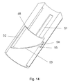
- figure 14 illustrates the inside surface of the housing 40 by showing the part of the housing 40 cut away in figure 13 seen from the backside.
- the four studs 46 on the shield 43 is guided in first horizontal tracks 51 provided on the inside surface of the housing 40.
- the locking protrusion 49 on the locking element 44 abuts a planar surface 48 in its initiate position and is guided in a second horizontal track 52 as the shield 43 is moved in the proximal direction.
- a not shown spring positioned between the bottom surface 50 and the locking element 44 will urge the locking element 44 and hence the shield 43 in the distal direction.
- the angled fore front 47 of the locking protrusion 49 will engage a diagonal track 53 also provided in the inside surface of the housing 40.
- the locking element 44 and hence the locking protrusion 49 will rotate approximately 180 degrees in the diagonal track 53 and engage a locking chamber 54 provided at the distal end of the diagonal track 53, which locking chamber 54 has a blocking surface 55 that a planar back front 56 of the locking protrusion 49 will abut rendering further movement of the shield 43 impossible.
- the first toothed ring 38 of the shield 43 and the second toothed ring 39 of the locking element 44 support this movement due to mutual engagement of the angled surfaces of the two rings 38, 39.
- the shield 43 cannot be rotated relatively to the housing 40 due to the engagement of the studs 46 with the first horizontal tracks 51. Since rotation of the shield 43 is inhibited it is impossible to rotate the locking protrusion 49 of the locking element 44 backwards in the diagonal track 53, and the locking protrusion 49 will therefore remain in the locking chamber 54 thus rendering the safety needle assembly secured.
- a window could be provided in the housing 40 through which window the locking chamber 54 can be viewed, such that the user can get a visible indication whether the safety needle assembly has been used or not.
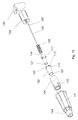
- the safety needle assembly shown in figure 15 comprises a housing made up from a needle hub 103 and a body 104 both preferably injection moulded from PP. Both the hub 103 itself and the tower of the hub 103 is somewhat higher than shown in figure 2, while the body 104 is somewhat shorter.
- the needle cannula 130 is inserted in the tower of the hub 103 and glued to the hub 103 by a blob of glue 160.
- the body 104 is in this embodiment provided with three windows 120 and the locking element 116 is also provided with three locking protrusions 117.
- the locking element 116 locks the safety needle assembly from reuse, the three locking protrusions 117 will be visible in the three windows 120 as earlier explained.
- the shield 104 which is preferably made from TPX can be transparent such that the tip of needle cannula 130 is visible for inspection by the user prior to injection, has on its proximal end six studs 110.
- the toothed ring 113 formed between these studs 110 is therefore in this embodiment only provided with six valleys.
- the locking element 116 which is preferably made from POM or PP is on the distal end surface provided with a serrated ring 161 which are used during the manufacturing process.
- a tool can enter the safety needle assembly through the needle outlet 107 in the shield 102 and engage this serrated ring 161 in order to rotate the locking element 116 to the correct position before the shield 102 and the locking element 116 is permanently encapsulated in the housing.
- the needle outlet 107 needs to be large enough for the toll to pass through the needle outlet 107.
- the studs 110 of the embodiment shown in figure 15 is provided with an additional guiding rib 162 which are guided in a number of not shown guiding tracks provided on the inside surface of the body 104 of the housing. Due to this no rotation between the shield 102 and the body 104 is possible,
- the removable seal 163 is preferably made from paper.
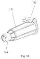
- the distal part of the container 131 can be formed as a cup 164 holding a predetermined volume as shown in figure 16.
- the dosage of an injection device to be used with the safety needle assembly can thus be controlled by ejecting a predetermined number of doses into the cup 164 and verifying the expelled volume. This can be done either by filling the entire cup or by having indications printed on the cup 164.
Landscapes
- Health & Medical Sciences (AREA)
- Engineering & Computer Science (AREA)
- Animal Behavior & Ethology (AREA)
- General Health & Medical Sciences (AREA)
- Biomedical Technology (AREA)
- Heart & Thoracic Surgery (AREA)
- Hematology (AREA)
- Life Sciences & Earth Sciences (AREA)
- Vascular Medicine (AREA)
- Anesthesiology (AREA)
- Public Health (AREA)
- Veterinary Medicine (AREA)
- Environmental & Geological Engineering (AREA)
- Physics & Mathematics (AREA)
- General Physics & Mathematics (AREA)
- Theoretical Computer Science (AREA)
- Infusion, Injection, And Reservoir Apparatuses (AREA)
- Portable Nailing Machines And Staplers (AREA)
Abstract
Description
- Figure 1
- Shows a perspective view of the safety needle assembly according to the invention.
- Figure 2
- Shows an exploded view of the safety needle assembly according to the invention.
- Figure 3
- Shows a perspective view of the needle shield.
- Figure 4
- Shows a perspective view of the locking element.
- Figure 5
- Shows a perspective view of the body of the housing.
- Figure 6
- Shows a schematically view of the body of the housing.
- Figure 7
- Shows a schematically view of the safety needle assembly according to the invention.
- Figure 8
- Shows a schematically view of the safety needle assembly according to the invention, with a part of the housing cut away.
- Figure 9
- Shows the locking protrusion in its first position.
- Figure 10
- Shows the locking protrusion in or moving towards its second position.
- Figure 11
- Shows the movement of the locking protrusion moving from the second to the third position.
- Figure 12
- Shows the locking protrusion in the third position.
- Figure 13
- Shows a perspective view of an embodiment of the safety needle assembly according to the invention.
- Figure 14
- Shows a part of the housing of an embodiment of the safety needle assembly according to the invention.
- Figure 15
- Shows an exploded view of the safety needle assembly according to the invention.
- Figure 16
- Shows a perspective view of the safety needle assembly stored in a container.
- 1
- Housing
- 2
- Shield
- 3
- Hub
- 4
- Body
- 5
- Connecting surface
- 6
- Top surface
- 7
- Needle outlet
- 8
- Opening
- 9
- Bottom surface
- 10
- Stud
- 11
- Planar ore front of studs
- 12
- Angled back front of studs
- 13
- Toothed ring
- 14
- Planar surface
- 15
- Blocking surface
- 16
- Locking element
- 17
- Locking protrusion
- 18
- Angled front of locking protrusion
- 19
- Planar back front of locking protrusion
- 20
- Window
- 21
- Rib
- 21a
- Upper part of rib
- 21b
- lower part of rib
- 22
- Fin
- 23
- Angled surface
- 24
- Collar
- 25
- Spring
- 26
- Spaces on shield
- 27
- Directional arrow
- 28
- Directional arrow
- 29
- Directional arrow
- 30
- Needle cannula
- 31
- Container
- 32
- distal surface of container
- 33
- proximal surface of container
- 34
- Ribs on outside surface of housing
- 35
- Thread
- 36
- Front end of locking protrusion
- 37
- Inner top end of shield
- 38
- Toothed ring of shield
- 39
- Second toothed ring of locking element
- 40
- Housing
- 41
- Hub
- 42
- Body
- 43
- Shield
- 44
- Locking element
- 45
- Opening
- 46
- Studs
- 47
- Angled fore front of locking protrusion
- 48
- Planar surface
- 49
- Locking protrusion
- 50
- Bottom surface
- 51
- First horizontal track
- 52
- Second horizontal track
- 53
- Diagonal track
- 54
- Locking chamber
- 55
- Blocking surface
- 56
- Planar back front
- 102
- Shield
- 103
- Hub
- 104
- Body
- 107
- Needle outlet
- 110
- Stud
- 113
- Toothed ring
- 116
- Locking element
- 117
- Locking protrusion
- 120
- Window
- 125
- Spring
- 130
- Needle cannula
- 131
- Container
- 160
- Glue
- 161
- Serrated ring
- 162
- Guiding rib
- 163
- Seal
- 164
- Cup
Wherein,
said locking element is a separate part provided between the spring and the shield and longitudinal moved simultaneously with the shield relatively to the housing during use, whereby the locking protrusion provided on the locking element is guided from a first position where the shield is in the distal position, via a second position where the shield is in the proximal position to a third position where the shield is in the distal position and in which third position at least one of the locking protrusions is blocked by a blocking surface provided on the inside surface of the housing whereby further movement of the shield is irreversible immobilized,
Claims (2)
- A Safety needle assembly comprisingcharacterized in that, the locking element (16, 44, 116) is a separate part, and that the at least one locking protrusion (17, 49, 117) engages the housing (1, 40, 103+104) to irreversible lock the shield (2, 43, 102) in the second distal position when the needle assembly is in the used condition, and whereina generally cylindrical housing (1, 40, 103+104) having a top surface (6) and a bottom surface (9, 50), the housing (1, 40, 103+104) having means for mounting the housing (1, 40, 103+104) onto a medical injection device,A needle cannula (30, 130) mounted in the bottom surface (9, 50), the needle cannula (30, 130) having a distal end located at a distal side of the bottom surface (9, 50),A shield (2, 43, 102) telescopically movable relatively to the housing (1, 40, 103+104) for movement between a first distal position where the shield (2, 43, 102) covers the distal end of the needle cannula (30, 130) when the needle assembly is in an unused condition, a proximal position where at least a part of the distal end of the needle cannula (30, 130) is exposed, and a second distal position where the shield (2, 43, 102) is locked in a position covering the distal end of the needle cannula (30, 130) when the needle assembly is in a used condition,A spring (25, 125) located inside the housing (1, 40, 103+104) urging the shield in the distal direction, andA locking element (16, 44, 116) provided inside the housing (1, 40, 103+104) and having at least one locking protrusion (17, 49, 117),
the housing (1) is provided with at least one transparent area (20, 120) through which transparent area (20, 120) a coloured part on the shield (2, 43, 102) and/or on the locking element (16, 44, 116) is visible when the needle assembly is in the unused condition indicating that the safety needle assembly is ready for use. - A safety needle assembly according to claim 1, characterized in that, the at least one locking protrusion (17, 49, 117) is provided with an indication which can be viewed through the transparent area (20, 120) when the needle assembly is in the used condition indicating that the safety needle assembly has been used.
Applications Claiming Priority (3)
| Application Number | Priority Date | Filing Date | Title |
|---|---|---|---|
| DKPA200101772 | 2001-11-30 | ||
| DK200101772 | 2001-11-30 | ||
| EP02803754A EP1448256B1 (en) | 2001-11-30 | 2002-11-28 | A safety needle assembly |
Related Parent Applications (1)
| Application Number | Title | Priority Date | Filing Date |
|---|---|---|---|
| EP02803754A Division EP1448256B1 (en) | 2001-11-30 | 2002-11-28 | A safety needle assembly |
Publications (4)
| Publication Number | Publication Date |
|---|---|
| EP1557191A2 true EP1557191A2 (en) | 2005-07-27 |
| EP1557191A3 EP1557191A3 (en) | 2005-10-12 |
| EP1557191B1 EP1557191B1 (en) | 2009-01-14 |
| EP1557191B2 EP1557191B2 (en) | 2016-09-07 |
Family
ID=8160860
Family Applications (2)
| Application Number | Title | Priority Date | Filing Date |
|---|---|---|---|
| EP02803754A Expired - Lifetime EP1448256B1 (en) | 2001-11-30 | 2002-11-28 | A safety needle assembly |
| EP05006983.0A Expired - Lifetime EP1557191B2 (en) | 2001-11-30 | 2002-11-28 | A safety needle assembly |
Family Applications Before (1)
| Application Number | Title | Priority Date | Filing Date |
|---|---|---|---|
| EP02803754A Expired - Lifetime EP1448256B1 (en) | 2001-11-30 | 2002-11-28 | A safety needle assembly |
Country Status (17)
| Country | Link |
|---|---|
| US (6) | US6855129B2 (en) |
| EP (2) | EP1448256B1 (en) |
| JP (1) | JP4603262B2 (en) |
| KR (1) | KR100879498B1 (en) |
| CN (1) | CN1294997C (en) |
| AT (2) | ATE316395T1 (en) |
| AU (1) | AU2002365290B2 (en) |
| CA (1) | CA2468243C (en) |
| DE (2) | DE60230933D1 (en) |
| DK (2) | DK1448256T3 (en) |
| ES (2) | ES2257597T3 (en) |
| IL (1) | IL161709A0 (en) |
| PL (1) | PL196617B1 (en) |
| PT (1) | PT1448256E (en) |
| RU (1) | RU2312679C2 (en) |
| WO (1) | WO2003045480A1 (en) |
| ZA (1) | ZA200403370B (en) |
Cited By (4)
| Publication number | Priority date | Publication date | Assignee | Title |
|---|---|---|---|---|
| WO2008025179A1 (en) * | 2006-09-01 | 2008-03-06 | Tecpharma Licensing Ag | Safety pin module comprising a locking mechanism and a user identification |
| WO2008028312A1 (en) * | 2006-09-06 | 2008-03-13 | Tecpharma Licensing Ag | Needle protection device with a blocked protection position |
| WO2008028304A1 (en) * | 2006-09-06 | 2008-03-13 | Tecpharma Licensing Ag | Needle protection device with a blocked protective position |
| JP2016032517A (en) * | 2014-07-31 | 2016-03-10 | 三菱鉛筆株式会社 | Needle protector |
Families Citing this family (293)
| Publication number | Priority date | Publication date | Assignee | Title |
|---|---|---|---|---|
| IL114960A0 (en) | 1995-03-20 | 1995-12-08 | Medimop Medical Projects Ltd | Flow control device |
| DE10009814B4 (en) | 2000-03-01 | 2008-03-06 | Tecpharma Licensing Ag | Disposable injector |
| US6547764B2 (en) | 2000-05-31 | 2003-04-15 | Novo Nordisk A/S | Double pointed injection needle |
| JP5058425B2 (en) * | 2000-08-02 | 2012-10-24 | ベクトン・ディキンソン・アンド・カンパニー | Pen needle and safety shield system |
| US7413562B2 (en) | 2001-03-15 | 2008-08-19 | Specialized Health Products, Inc. | Safety shield for medical needles |
| US6984223B2 (en) * | 2001-11-13 | 2006-01-10 | Becton, Dickinson And Company | Needle safety device |
| DK1448256T3 (en) | 2001-11-30 | 2006-05-29 | Novo Nordisk As | safety needle |
| US20100160869A1 (en) * | 2002-06-22 | 2010-06-24 | Barry Peter Liversidge | Medical Needle Assemblies |
| US20050160858A1 (en) * | 2002-07-24 | 2005-07-28 | M 2 Medical A/S | Shape memory alloy actuator |
| AU2003245872A1 (en) * | 2002-07-24 | 2004-02-09 | M 2 Medical A/S | An infusion pump system, an infusion pump unit and an infusion pump |
| US11083841B2 (en) | 2002-08-09 | 2021-08-10 | Fenwal, Inc. | Needle protector, needle assembly and fluid processing set including the same |
| JP2006504476A (en) * | 2002-11-05 | 2006-02-09 | エム2・メディカル・アクティーゼルスカブ | Disposable, wearable insulin administration device, combination of the device and program control device, and operation control method of the device |
| EP1583571B1 (en) * | 2002-12-23 | 2008-02-13 | M2 Medical A/S | Medical dispensing device for insulin |
| DK1583573T3 (en) * | 2002-12-23 | 2011-05-09 | Asante Solutions Inc | Flexible piston rod |
| US8932264B2 (en) * | 2003-08-11 | 2015-01-13 | Becton, Dickinson And Company | Medication delivery pen assembly with needle locking safety shield |
| GB0406458D0 (en) * | 2003-10-09 | 2004-04-28 | Liversidge Barry P | Safety medical needle assemblies |
| US7101351B2 (en) | 2003-11-03 | 2006-09-05 | Becton, Dickinson And Company | Safety device for a syringe |
| US7468054B2 (en) | 2003-11-03 | 2008-12-23 | Becton, Dickinson And Company | Safety shield system for a syringe |
| US7497847B2 (en) | 2003-11-03 | 2009-03-03 | Becton, Dickinson And Company | Safety shield system for a syringe |
| GB0327136D0 (en) * | 2003-11-21 | 2003-12-24 | Nmt Group Plc | Safety needle |
| CN100571796C (en) * | 2003-11-25 | 2009-12-23 | 特殊健康产品公司 | Safety shield for resettable medical needle |
| US20050159768A1 (en) * | 2004-01-15 | 2005-07-21 | Home Diagnostics, Inc. | Lancing device |
| US7344517B2 (en) | 2004-01-20 | 2008-03-18 | Becton, Dickinson And Company | Syringe having a retractable needle |
| US7604613B2 (en) | 2004-01-20 | 2009-10-20 | Beckton, Dickinson And Company | Syringe having a retractable needle |
| US7753879B2 (en) * | 2004-01-29 | 2010-07-13 | M2 Group Holdings, Inc. | Disposable medicine dispensing device |
| IL161660A0 (en) | 2004-04-29 | 2004-09-27 | Medimop Medical Projects Ltd | Liquid drug delivery device |
| ES2293416T3 (en) * | 2004-05-29 | 2008-03-16 | Gerresheimer Bunde Gmbh | SYRINGE CLOSURE AND PROCEDURE FOR MANUFACTURING AND A SYRINGE CLOSURE. |
| WO2006086825A1 (en) * | 2005-01-17 | 2006-08-24 | Biomd Limited | Improved needle assembly |
| USD538930S1 (en) * | 2005-01-28 | 2007-03-20 | Matsushita Electric Industrial Co., Ltd. | Puncture needle cartridge |
| US8062252B2 (en) | 2005-02-18 | 2011-11-22 | Becton, Dickinson And Company | Safety shield system for a syringe |
| CN1824339B (en) * | 2005-02-21 | 2011-05-11 | 住友电木株式会社 | Medical implement |
| WO2006105793A1 (en) * | 2005-04-06 | 2006-10-12 | M 2 Medical A/S | Method and device for dispensing liquid medicine by means of a twistable element |
| US8241254B2 (en) * | 2005-04-15 | 2012-08-14 | Specialized Health Products, Inc. | Medical needle systems with reset devices for medical needle shield apparatus |
| US8070739B2 (en) | 2005-08-11 | 2011-12-06 | Medimop Medical Projects Ltd. | Liquid drug transfer devices for failsafe correct snap fitting onto medicinal vials |
| GB0517699D0 (en) | 2005-09-01 | 2005-10-05 | Owen Mumford Ltd | Needle shroud assembly |
| WO2007026163A1 (en) | 2005-09-01 | 2007-03-08 | Owen Mumford Limited | Needle shroud assembly |
| EP1933901B1 (en) * | 2005-09-26 | 2014-12-31 | Asante Solutions, Inc. | Portable infusion pump having a flexible pushrod with hinged portions |
| US8409142B2 (en) | 2005-09-26 | 2013-04-02 | Asante Solutions, Inc. | Operating an infusion pump system |
| US8105279B2 (en) * | 2005-09-26 | 2012-01-31 | M2 Group Holdings, Inc. | Dispensing fluid from an infusion pump system |
| US8551046B2 (en) | 2006-09-18 | 2013-10-08 | Asante Solutions, Inc. | Dispensing fluid from an infusion pump system |
| US7534226B2 (en) * | 2005-09-26 | 2009-05-19 | M2 Group Holdings, Inc. | Dispensing fluid from an infusion pump system |
| US8057436B2 (en) | 2005-09-26 | 2011-11-15 | Asante Solutions, Inc. | Dispensing fluid from an infusion pump system |
| WO2007056592A2 (en) | 2005-11-08 | 2007-05-18 | M2 Medical A/S | Method and system for manual and autonomous control of an infusion pump |
| DK1951340T4 (en) * | 2005-11-08 | 2017-05-22 | Bigfoot Biomedical Inc | infusion pump |
| EP1970008A1 (en) * | 2005-12-12 | 2008-09-17 | Nichinan Corporation | Puncture needle device |
| GB0600212D0 (en) | 2006-01-06 | 2006-02-15 | Liversidge Barry P | Medical needle safety device |
| US7708718B2 (en) * | 2006-03-17 | 2010-05-04 | Zehner John A | Syringe shield |
| FR2899482A1 (en) * | 2006-04-11 | 2007-10-12 | Becton Dickinson France Soc Pa | AUTOMATIC INJECTION DEVICE |
| GB2438591B (en) * | 2006-06-01 | 2011-07-13 | Cilag Gmbh Int | Injection device |
| DE102006042233B3 (en) * | 2006-09-06 | 2008-03-06 | Tecpharma Licensing Ag | Needle guard with distal and proximal needle guard |
| CN101657226A (en) * | 2006-09-28 | 2010-02-24 | 摩根医疗科技公司 | Venous cannula assembly |
| GB0620117D0 (en) | 2006-10-11 | 2006-11-22 | Liversidge Barry P | Safety needle pack |
| ES2374847T3 (en) * | 2006-11-22 | 2012-02-22 | Mallinckrodt Llc | UNIVERSAL ADAPTER FOR A SYMBOL OF SYRINGE. |
| US8002756B2 (en) * | 2006-12-08 | 2011-08-23 | Becton, Dickinson And Company | Method and apparatus for delivering a therapeutic substance through an injection port |
| US8251951B2 (en) | 2006-12-13 | 2012-08-28 | Suzuken Company Limited | Injection needle cartridge and injector |
| ATE495777T1 (en) | 2006-12-22 | 2011-02-15 | Novo Nordisk As | SHIELDABLE NEEDLE ARRANGEMENT WITH PRE-TENSIONED SAFETY SHIELD |
| US7871397B2 (en) | 2006-12-26 | 2011-01-18 | Stat Medical Devices, Inc. | Pen needle tip |
| US7540858B2 (en) | 2007-01-23 | 2009-06-02 | Becton, Dickinson And Company | Retracting safety pen needle |
| US7462169B2 (en) | 2007-01-23 | 2008-12-09 | Becton, Dickinson And Company | Safety shield system for an injection pen needle |
| DE102007009340A1 (en) * | 2007-02-27 | 2008-08-28 | Tecpharma Licensing Ag | Needle protection device for injection unit, has needle support, which has needle protective sleeve and integrated needle support removal device for removing needle support of injection unit |
| EP2134393B1 (en) * | 2007-03-07 | 2017-09-20 | Novo Nordisk A/S | Back needle |
| BRPI0808632B8 (en) | 2007-03-07 | 2021-06-22 | Becton Dickinson Co | Protective Needle Set with Indicator |
| SG146472A1 (en) * | 2007-03-27 | 2008-10-30 | Agency Science Tech & Res | Safety guard for syringe needle |
| SG147319A1 (en) * | 2007-04-11 | 2008-11-28 | Agency Science Tech & Res | Safety guard for syringe needle |
| IL182605A0 (en) | 2007-04-17 | 2007-07-24 | Medimop Medical Projects Ltd | Fluid control device with manually depressed actuator |
| US9259174B2 (en) * | 2007-04-20 | 2016-02-16 | Stat Medical Devices, Inc. | Retractable fluid collection device |
| USD565732S1 (en) * | 2007-04-23 | 2008-04-01 | West Pharmaceutical Services, Inc. | Needle shield |
| US7981102B2 (en) | 2007-05-21 | 2011-07-19 | Asante Solutions, Inc. | Removable controller for an infusion pump |
| US7833196B2 (en) | 2007-05-21 | 2010-11-16 | Asante Solutions, Inc. | Illumination instrument for an infusion pump |
| US7794426B2 (en) | 2007-05-21 | 2010-09-14 | Asante Solutions, Inc. | Infusion pump system with contamination-resistant features |
| US7892199B2 (en) * | 2007-05-21 | 2011-02-22 | Asante Solutions, Inc. | Occlusion sensing for an infusion pump |
| GB2449491A (en) * | 2007-05-25 | 2008-11-26 | Iden Shams | Needle assembly with a locking protective sheath |
| US7717903B2 (en) | 2007-09-06 | 2010-05-18 | M2 Group Holdings, Inc. | Operating an infusion pump system |
| US7828528B2 (en) * | 2007-09-06 | 2010-11-09 | Asante Solutions, Inc. | Occlusion sensing system for infusion pumps |
| US7935076B2 (en) | 2007-09-07 | 2011-05-03 | Asante Solutions, Inc. | Activity sensing techniques for an infusion pump system |
| US8032226B2 (en) | 2007-09-07 | 2011-10-04 | Asante Solutions, Inc. | User profile backup system for an infusion pump device |
| US8287514B2 (en) | 2007-09-07 | 2012-10-16 | Asante Solutions, Inc. | Power management techniques for an infusion pump system |
| CA2639322C (en) | 2007-09-07 | 2016-11-08 | Becton, Dickinson And Company | Pen needle hub having increased contact area |
| US7879026B2 (en) | 2007-09-07 | 2011-02-01 | Asante Solutions, Inc. | Controlled adjustment of medicine dispensation from an infusion pump device |
| WO2009038860A2 (en) | 2007-09-18 | 2009-03-26 | Medeq Llc | Medicament mixing and injection apparatus |
| IL186290A0 (en) | 2007-09-25 | 2008-01-20 | Medimop Medical Projects Ltd | Liquid drug delivery devices for use with syringe having widened distal tip |
| US7981094B2 (en) * | 2007-09-28 | 2011-07-19 | Tyco Healthcare Group Lp | Two position septum for implantable vascular access device |
| JP5394938B2 (en) * | 2008-01-29 | 2014-01-22 | テルモ株式会社 | Puncture needle assembly and chemical injection device |
| JP4824709B2 (en) * | 2008-02-01 | 2011-11-30 | ▲恵▼碁生物科技股▲分▼有限公司 | Safety blood collection device |
| ITMI20080218A1 (en) | 2008-02-13 | 2009-08-14 | Artsana Spa | NEEDLE SAFETY PEN WITH PROTECTIVE ELEMENT FOR CANNULA |
| USD639939S1 (en) * | 2008-03-04 | 2011-06-14 | Carmel Pharma Ab | Medical device |
| ES2729650T3 (en) | 2008-03-13 | 2019-11-05 | Becton Dickinson Co | Safety needle set |
| WO2009114762A1 (en) | 2008-03-13 | 2009-09-17 | Becton, Dickinson And Company | Safety pen needle assembly having shielding for patient and non-patient ends |
| CA2719209C (en) | 2008-03-13 | 2016-10-18 | Becton, Dickinson And Company | Safety pen needle assembly having shield for non-patient end |
| WO2009119770A1 (en) * | 2008-03-28 | 2009-10-01 | テルモ株式会社 | Puncture needle assembly and medicinal liquid injector |
| US7811261B2 (en) | 2008-06-02 | 2010-10-12 | Sta-Med, Llc | Needle cover assembly for a syringe |
| EP2298394A4 (en) | 2008-06-20 | 2017-11-22 | Nipro Corporation | Needle assembly |
| US7785296B2 (en) * | 2008-07-17 | 2010-08-31 | Smiths Medical Asd, Inc. | Needle tip spring protector |
| US7959598B2 (en) | 2008-08-20 | 2011-06-14 | Asante Solutions, Inc. | Infusion pump systems and methods |
| GB2463034B (en) * | 2008-08-28 | 2012-11-07 | Owen Mumford Ltd | Autoinjection devices |
| GB0815748D0 (en) * | 2008-08-29 | 2008-10-08 | Liversidge Barry P | Medical needle assembly |
| US8439870B2 (en) * | 2008-09-10 | 2013-05-14 | B. Braun Medical Inc. | Safety needle assembly and methods |
| US12097357B2 (en) | 2008-09-15 | 2024-09-24 | West Pharma. Services IL, Ltd. | Stabilized pen injector |
| EP2355879B1 (en) | 2008-11-17 | 2016-03-23 | Becton Dickinson and Company | Additive force device for drug delivery pen for intradermal medication injection |
| WO2010090734A1 (en) * | 2009-02-06 | 2010-08-12 | Becton, Dickinson And Company | Pen needle assembly having biodegradable components |
| JP5727391B2 (en) * | 2009-02-06 | 2015-06-03 | ベクトン・ディキンソン・アンド・カンパニーBecton, Dickinson And Company | Disposable pen needle with anti-reuse function |
| KR101107199B1 (en) * | 2009-02-19 | 2012-01-25 | 설재원 | Pen needle packing device |
| USD627459S1 (en) | 2009-03-10 | 2010-11-16 | Nipro Corporation | Needle for medical purposes |
| WO2010103950A1 (en) * | 2009-03-11 | 2010-09-16 | テルモ株式会社 | Puncture needle assembly and medicinal liquid injection device |
| USD641080S1 (en) | 2009-03-31 | 2011-07-05 | Medimop Medical Projects Ltd. | Medical device having syringe port with locking mechanism |
| JP5433075B2 (en) * | 2009-04-27 | 2014-03-05 | エス・ホー・エル・グループ・アクチボラゲット | Safety pen needle device |
| US20110023281A1 (en) * | 2009-04-30 | 2011-02-03 | Stat Medical Devices, Inc. | Pen injection device cap with integral pen needle quick release and/or removal system |
| US9700681B2 (en) * | 2009-05-15 | 2017-07-11 | Stat Medical Devices, Inc. | Pen needle with quick release and/or removal system |
| US8876781B2 (en) * | 2009-06-18 | 2014-11-04 | Shl Group Ab | Safety pen needle device |
| US20110060292A1 (en) * | 2009-08-14 | 2011-03-10 | Stat Medical Devices, Inc. | Pen needle storage device with integral removal and/or installation system |
| US20110071492A1 (en) * | 2009-09-18 | 2011-03-24 | Becton, Dickinson And Company | Hub assembly having a hidden needle for a drug delivery pen |
| WO2011039227A2 (en) * | 2009-09-30 | 2011-04-07 | Sanofi-Aventis Deutschland Gmbh | Method and assembly for a drug delivery device |
| IL201323A0 (en) | 2009-10-01 | 2010-05-31 | Medimop Medical Projects Ltd | Fluid transfer device for assembling a vial with pre-attached female connector |
| IL202069A0 (en) | 2009-11-12 | 2010-06-16 | Medimop Medical Projects Ltd | Fluid transfer device with sealing arrangement |
| IL202070A0 (en) | 2009-11-12 | 2010-06-16 | Medimop Medical Projects Ltd | Inline liquid drug medical device |
| US8663174B2 (en) | 2009-11-13 | 2014-03-04 | Becton, Dickinson And Company | Hub assembly having a hidden needle for a drug delivery pen |
| US8480646B2 (en) * | 2009-11-20 | 2013-07-09 | Carmel Pharma Ab | Medical device connector |
| WO2011095489A1 (en) * | 2010-02-05 | 2011-08-11 | Sanofi-Aventis Deutschland Gmbh | Push rod activated medicated module |
| EP2531239A1 (en) | 2010-02-05 | 2012-12-12 | Sanofi-Aventis Deutschland GmbH | Medicated module having a double needle guard |
| CN102844065B (en) * | 2010-02-05 | 2015-10-14 | 赛诺菲-安万特德国有限公司 | Band can the medicine carrying module of needle shield of locking |
| CA2788737A1 (en) * | 2010-02-05 | 2011-08-11 | Sanofi-Aventis Deutschland Gmbh | Medicated module with lockable needle guard |
| DK2512399T3 (en) | 2010-02-24 | 2015-06-22 | Medimop Medical Projects Ltd | Fluid transfer device with vent arrangement |
| BR112012020829B1 (en) | 2010-02-24 | 2020-04-14 | Medimop Medical Projects Ltd | liquid drug transfer device for use with a medical bottle |
| US9333306B2 (en) | 2010-03-25 | 2016-05-10 | Sanofi-Aventis Deutschland Gmbh | Needle assembly |
| BR112012024330A2 (en) | 2010-03-25 | 2017-07-18 | Sanofi Aventis Deutschland | drug module with user selection and drug delivery system |
| KR20130092423A (en) | 2010-04-23 | 2013-08-20 | 사노피-아벤티스 도이칠란트 게엠베하 | Cartridge holder and alignment interface |
| WO2011140596A1 (en) * | 2010-05-11 | 2011-11-17 | Noble House Group Pty. Ltd. | Medical sampling port |
| JP5657786B2 (en) * | 2010-05-26 | 2015-01-21 | ベクトン・ディキンソン・アンド・カンパニーBecton, Dickinson And Company | Safety needle assembly |
| USD669165S1 (en) | 2010-05-27 | 2012-10-16 | Asante Solutions, Inc. | Infusion pump |
| US8162882B2 (en) | 2010-06-23 | 2012-04-24 | Sta-Med, Llc | Automatic-locking safety needle covers and methods of use and manufacture |
| SG186320A1 (en) * | 2010-07-02 | 2013-02-28 | Sanofi Aventis Deutschland | Safety device for a pre-filled syringe and injection device |
| EP2585145B1 (en) | 2010-08-19 | 2014-03-05 | West Pharmaceutical Services, Inc. | Rigid needle shield |
| USD669980S1 (en) | 2010-10-15 | 2012-10-30 | Medimop Medical Projects Ltd. | Vented vial adapter |
| US10463803B2 (en) | 2010-11-12 | 2019-11-05 | Stat Medical Devices, Inc. | Pen needle with quick release and/or removal system |
| IL209290A0 (en) | 2010-11-14 | 2011-01-31 | Medimop Medical Projects Ltd | Inline liquid drug medical device having rotary flow control member |
| GB201020472D0 (en) * | 2010-12-02 | 2011-01-19 | Oval Medical Technologies Ltd | A drive assembly for an autoinjector |
| MX2013007487A (en) | 2010-12-31 | 2013-08-15 | Novo Nordisk As | Medical injection device. |
| US8852152B2 (en) | 2011-02-09 | 2014-10-07 | Asante Solutions, Inc. | Infusion pump systems and methods |
| US8961470B2 (en) | 2011-02-17 | 2015-02-24 | Steven Schraga | Pen needle with safety shield system |
| US8454581B2 (en) | 2011-03-16 | 2013-06-04 | Asante Solutions, Inc. | Infusion pump systems and methods |
| IL212420A0 (en) | 2011-04-17 | 2011-06-30 | Medimop Medical Projects Ltd | Liquid drug transfer assembly |
| US9504627B2 (en) | 2011-04-21 | 2016-11-29 | Sanofi-Aventis Deutschland Gmbh | Medicated module for a drug delivery device |
| EP2517746A1 (en) * | 2011-04-29 | 2012-10-31 | Sanofi-Aventis Deutschland GmbH | Needle assembly storage system |
| USD655001S1 (en) | 2011-05-10 | 2012-02-28 | West Pharmaceutical Services Deutschland Gmbh & Co. Kg | Needle shield |
| WO2012166746A1 (en) | 2011-05-31 | 2012-12-06 | Sta-Med, Llc | Blood collection safety devices and methods of use and manufacture |
| BR112013032089A2 (en) * | 2011-06-17 | 2016-12-13 | Sanofi Aventis Deutschland | drug delivery device for administering a predefined dose of a drug |
| JP5918483B2 (en) * | 2011-06-21 | 2016-05-18 | 株式会社スズケン | Prefilled syringe |
| US8585657B2 (en) | 2011-06-21 | 2013-11-19 | Asante Solutions, Inc. | Dispensing fluid from an infusion pump system |
| WO2013015136A1 (en) | 2011-07-27 | 2013-01-31 | 久光製薬株式会社 | Applicator |
| TWD152768S (en) * | 2011-07-27 | 2013-04-01 | 久光製藥股份有限公司 | Applicator device |
| US20130053751A1 (en) * | 2011-08-31 | 2013-02-28 | Frank Holtham | Needle with an antiseptic swab |
| US8808230B2 (en) | 2011-09-07 | 2014-08-19 | Asante Solutions, Inc. | Occlusion detection for an infusion pump system |
| EP2572741A1 (en) * | 2011-09-23 | 2013-03-27 | Sanofi-Aventis Deutschland GmbH | Medicament delivery device and actuation mechanism for a drug delivery device |
| EP2578255A1 (en) * | 2011-10-06 | 2013-04-10 | Sanofi-Aventis Deutschland GmbH | Needle safety device |
| IL215699A0 (en) | 2011-10-11 | 2011-12-29 | Medimop Medical Projects Ltd | Liquid drug reconstitution assemblage for use with iv bag and drug vial |
| JP5844605B2 (en) | 2011-10-31 | 2016-01-20 | 株式会社スズケン | Syringe |
| ES2779624T3 (en) | 2011-11-07 | 2020-08-18 | Safety Syringes Inc | Needle guard with contact trigger activation |
| US9078978B2 (en) | 2011-12-28 | 2015-07-14 | Stat Medical Devices, Inc. | Needle assembly with safety system for a syringe or fluid sampling device and method of making and using the same |
| USD737436S1 (en) | 2012-02-13 | 2015-08-25 | Medimop Medical Projects Ltd. | Liquid drug reconstitution assembly |
| USD674088S1 (en) | 2012-02-13 | 2013-01-08 | Medimop Medical Projects Ltd. | Vial adapter |
| USD720451S1 (en) | 2012-02-13 | 2014-12-30 | Medimop Medical Projects Ltd. | Liquid drug transfer assembly |
| US10004854B2 (en) | 2012-03-07 | 2018-06-26 | West Pharmaceutical Services, Inc. | Low radial profile needle safety device |
| US9907916B2 (en) | 2012-03-07 | 2018-03-06 | West Pharmaceutical Services, Inc. | Low radial profile needle safety device |
| US9186466B2 (en) | 2012-03-14 | 2015-11-17 | Becton, Dickinson And Company | Passively activated safety needle assemblies and methods of use |
| IL219065A0 (en) | 2012-04-05 | 2012-07-31 | Medimop Medical Projects Ltd | Fluid transfer device with manual operated cartridge release arrangement |
| US9278179B2 (en) | 2012-06-20 | 2016-03-08 | Safety Syringes, Inc. | Contact trigger release needle guard with elastic spring |
| WO2014004348A1 (en) * | 2012-06-29 | 2014-01-03 | Amgen Inc. | Blister pack |
| JP5963047B2 (en) * | 2012-07-11 | 2016-08-03 | ニプロ株式会社 | Needle assembly |
| US8454557B1 (en) | 2012-07-19 | 2013-06-04 | Asante Solutions, Inc. | Infusion pump system and method |
| US8454562B1 (en) | 2012-07-20 | 2013-06-04 | Asante Solutions, Inc. | Infusion pump system and method |
| IL221634A0 (en) | 2012-08-26 | 2012-12-31 | Medimop Medical Projects Ltd | Universal drug vial adapter |
| IL221635A0 (en) | 2012-08-26 | 2012-12-31 | Medimop Medical Projects Ltd | Drug vial mixing and transfer device for use with iv bag and drug vial |
| ES2659491T3 (en) * | 2012-09-05 | 2018-03-15 | E3D Agricultural Cooperative Association Ltd. | Electronic self-injection device |
| DK2895218T3 (en) * | 2012-09-11 | 2018-04-03 | Sanofi Aventis Deutschland | DRIVE MECHANISM FOR A PHARMACEUTICAL ADMINISTRATION AND PHARMACEUTICAL ADMINISTRATION DEVICE |
| EP2872100B1 (en) | 2012-09-13 | 2017-03-29 | Medimop Medical Projects Ltd | Telescopic female drug vial adapter |
| JP6647043B2 (en) * | 2012-10-25 | 2020-02-14 | ノボ・ノルデイスク・エー/エス | Pre-filled disposable injection device |
| USD734868S1 (en) | 2012-11-27 | 2015-07-21 | Medimop Medical Projects Ltd. | Drug vial adapter with downwardly depending stopper |
| US9427523B2 (en) | 2012-12-10 | 2016-08-30 | Bigfoot Biomedical, Inc. | Infusion pump system and method |
| US20140276536A1 (en) | 2013-03-14 | 2014-09-18 | Asante Solutions, Inc. | Infusion Pump System and Methods |
| US9446186B2 (en) | 2013-03-01 | 2016-09-20 | Bigfoot Biomedical, Inc. | Operating an infusion pump system |
| IL225734A0 (en) | 2013-04-14 | 2013-09-30 | Medimop Medical Projects Ltd | Ready-to-use drug vial assemblages including drug vial and drug vial closure having fluid transfer member, and drug vial closure therefor |
| CN105228676B (en) | 2013-05-10 | 2018-01-05 | 麦迪麦珀医疗工程有限公司 | Include the medical treatment device of the vial adapter with inline dry kit |
| CA2947955C (en) * | 2013-05-17 | 2020-07-07 | Carrtech Llc | Filtering needle cap |
| US9446187B2 (en) | 2013-06-03 | 2016-09-20 | Bigfoot Biomedical, Inc. | Infusion pump system and method |
| US9457141B2 (en) | 2013-06-03 | 2016-10-04 | Bigfoot Biomedical, Inc. | Infusion pump system and method |
| WO2014196051A1 (en) * | 2013-06-06 | 2014-12-11 | テルモ株式会社 | Catheter assembly |
| US10500376B2 (en) | 2013-06-07 | 2019-12-10 | Becton, Dickinson And Company | IV catheter having external needle shield and internal blood control septum |
| US9561324B2 (en) | 2013-07-19 | 2017-02-07 | Bigfoot Biomedical, Inc. | Infusion pump system and method |
| USD765837S1 (en) | 2013-08-07 | 2016-09-06 | Medimop Medical Projects Ltd. | Liquid transfer device with integral vial adapter |
| GB2533714B (en) | 2013-08-07 | 2020-04-08 | Medimop Medical Projects Ltd | Liquid transfer devices for use with infusion liquid containers |
| USD767124S1 (en) | 2013-08-07 | 2016-09-20 | Medimop Medical Projects Ltd. | Liquid transfer device with integral vial adapter |
| US9078983B2 (en) | 2013-08-19 | 2015-07-14 | Becton, Dickinson And Company | Prefilled safety pen needle |
| US10569015B2 (en) | 2013-12-02 | 2020-02-25 | Bigfoot Biomedical, Inc. | Infusion pump system and method |
| CA2873681C (en) | 2013-12-10 | 2022-05-24 | Becton, Dickinson And Company | Passive safety pen needle assembly |
| ES2863959T3 (en) | 2013-12-10 | 2021-10-13 | Becton Dickinson Co | Active Safety Pen Needle Assembly |
| EP2886147A1 (en) * | 2013-12-20 | 2015-06-24 | Sanofi-Aventis Deutschland GmbH | Safety device for a drug delivery device |
| JP6495329B2 (en) | 2014-01-06 | 2019-04-03 | ノボ・ノルデイスク・エー/エス | Shielding mechanism for injection devices |
| CN106029138A (en) * | 2014-02-24 | 2016-10-12 | 诺和诺德股份有限公司 | injection device |
| US10232121B2 (en) | 2014-03-21 | 2019-03-19 | Novo Nordisk A/S | Injection device having automatic needle retraction |
| WO2015150179A1 (en) | 2014-04-03 | 2015-10-08 | Novo Nordisk A/S | A needle arrangement |
| US9555221B2 (en) | 2014-04-10 | 2017-01-31 | Smiths Medical Asd, Inc. | Constant force hold tip protector for a safety catheter |
| AU2015247343B2 (en) | 2014-04-18 | 2019-08-29 | Becton, Dickinson And Company | Needle capture safety interlock for catheter |
| US10118000B2 (en) | 2014-04-21 | 2018-11-06 | Stat Medical Devices, Inc. | Pen needle installation and removal safety cover and pen needle assembly utilizing the same |
| US9629901B2 (en) | 2014-07-01 | 2017-04-25 | Bigfoot Biomedical, Inc. | Glucagon administration system and methods |
| US10155091B2 (en) | 2014-07-11 | 2018-12-18 | Stat Medical Devices, Inc. | Pen needle tip and method of making and using the same |
| US10137246B2 (en) | 2014-08-06 | 2018-11-27 | Bigfoot Biomedical, Inc. | Infusion pump assembly and method |
| US9919096B2 (en) | 2014-08-26 | 2018-03-20 | Bigfoot Biomedical, Inc. | Infusion pump system and method |
| USD757933S1 (en) | 2014-09-11 | 2016-05-31 | Medimop Medical Projects Ltd. | Dual vial adapter assemblage |
| US10751479B2 (en) | 2014-10-08 | 2020-08-25 | Shl Medical Ag | Needle cover assembly |
| CN104307072A (en) * | 2014-10-29 | 2015-01-28 | 杭州普昂医疗科技有限公司 | Safety insulin pen |
| CN204219537U (en) * | 2014-11-04 | 2015-03-25 | 温州市贝普科技有限公司 | Single use safety destructing insulin pin |
| US11511052B2 (en) | 2014-11-10 | 2022-11-29 | Becton, Dickinson And Company | Safety IV catheter with V-clip interlock and needle tip capture |
| US20160166821A1 (en) * | 2014-12-15 | 2016-06-16 | Intermountain Invention Management, Llc | Devices for restraining movement of elongated medical implements and related systems and methods |
| CN104436369A (en) * | 2014-12-30 | 2015-03-25 | 江苏华阳电器有限公司 | Implicit needle mechanism of injector |
| EP3217944B1 (en) | 2015-01-05 | 2019-04-10 | West Pharma. Services IL, Ltd | Dual vial adapter assemblages with quick release drug vial adapter for ensuring correct usage |
| US9415176B1 (en) | 2015-01-22 | 2016-08-16 | West Pharmaceutical Services, Inc. | Autoinjector having an end-of-dose visual indicator |
| CN104771815B (en) * | 2015-04-28 | 2017-05-03 | 苏州施莱医疗器械有限公司 | Insulin syringe needle with needle tip protection function |
| US9878097B2 (en) | 2015-04-29 | 2018-01-30 | Bigfoot Biomedical, Inc. | Operating an infusion pump system |
| US10357429B2 (en) | 2015-07-16 | 2019-07-23 | West Pharma. Services IL, Ltd. | Liquid drug transfer devices for secure telescopic snap fit on injection vials |
| US11529473B2 (en) | 2015-11-03 | 2022-12-20 | Dali Medical Devices Ltd. | Safety needles and methods of use thereof |
| WO2017077537A1 (en) | 2015-11-03 | 2017-05-11 | Dali Medical Devices Ltd. | Safety needles and methods of use thereof |
| USD801522S1 (en) | 2015-11-09 | 2017-10-31 | Medimop Medical Projects Ltd. | Fluid transfer assembly |
| CN105232332B (en) * | 2015-11-20 | 2018-04-13 | 山东新华安得医疗用品有限公司 | The anti-closed dispensing needle of safety of acupuncture |
| BR112018010435B1 (en) | 2015-11-25 | 2022-06-28 | West Pharma. Services IL, Ltd. | DOUBLE AMPOULE ADAPTER SET FOR USE WITH A SYRINGE WITHOUT NEEDLE WITH A MALE CONNECTOR, A DRUG AMPOULE AND A LIQUID AMPOULE |
| US10449294B1 (en) | 2016-01-05 | 2019-10-22 | Bigfoot Biomedical, Inc. | Operating an infusion pump system |
| HK1257215A1 (en) | 2016-01-05 | 2019-10-18 | Bigfoot Biomedical, Inc. | Operating multi-modal medicine delivery systems |
| HK1256995A1 (en) | 2016-01-14 | 2019-10-11 | Bigfoot Biomedical, Inc. | Occlusion resolution in medication delivery devices, systems, and methods |
| WO2017136898A1 (en) | 2016-02-11 | 2017-08-17 | Somark Group Limited | A radio device for implantation in an animal, a method for making a radio device for implantation in an animal, a method for providing electrical power to a radio device attached to an animal, a method for implanting a radio device into an animal, an animal having implanted therein a radio device, and a radio device implanted in an animal |
| USD809134S1 (en) | 2016-03-10 | 2018-01-30 | Bigfoot Biomedical, Inc. | Infusion pump assembly |
| IL245800A0 (en) | 2016-05-24 | 2016-08-31 | West Pharma Services Il Ltd | Dual vial adapter assemblages including identical twin vial adapters |
| IL245803A0 (en) | 2016-05-24 | 2016-08-31 | West Pharma Services Il Ltd | Dual vial adapter assemblages including vented drug vial adapter and vented liquid vial adapter |
| TWM529948U (en) * | 2016-06-01 | 2016-10-01 | 啟碁科技股份有限公司 | Communication device |
| IL246073A0 (en) | 2016-06-06 | 2016-08-31 | West Pharma Services Il Ltd | Fluid transfer devices for use with drug pump cartridge having slidable driving plunger |
| IL247376A0 (en) | 2016-08-21 | 2016-12-29 | Medimop Medical Projects Ltd | Syringe assembly |
| WO2018064222A1 (en) | 2016-09-27 | 2018-04-05 | Bigfoot Biomedical, Inc. | Medicine injection and disease management systems, devices, and methods |
| USD832430S1 (en) | 2016-11-15 | 2018-10-30 | West Pharma. Services IL, Ltd. | Dual vial adapter assemblage |
| US20180140783A1 (en) * | 2016-11-22 | 2018-05-24 | E3D Agricultural Cooperative Association Ltd | Actuated needle shielding and shething device |
| IL249408A0 (en) | 2016-12-06 | 2017-03-30 | Medimop Medical Projects Ltd | A device for transporting fluids for use with an infusion fluid container and a hand tool similar to a plunger to release a vial from it |
| US11103651B2 (en) * | 2016-12-13 | 2021-08-31 | Beckon, Dickinson and Company | Safety needle devices |
| US10792438B2 (en) * | 2016-12-13 | 2020-10-06 | Becton, Dickinson And Company | Safety needle devices |
| AU2017376111B2 (en) | 2016-12-12 | 2023-02-02 | Bigfoot Biomedical, Inc. | Alarms and alerts for medication delivery devices and related systems and methods |
| US11147910B2 (en) | 2016-12-12 | 2021-10-19 | Becton, Dickinson And Company | Packaging for safety needle |
| USD836769S1 (en) | 2016-12-12 | 2018-12-25 | Bigfoot Biomedical, Inc. | Insulin delivery controller |
| US11173253B2 (en) | 2016-12-12 | 2021-11-16 | Becton, Dickinson And Company | Packaging for safety needle |
| US10661026B2 (en) | 2016-12-13 | 2020-05-26 | Becton, Dickinson And Company | Safety needle device |
| US10589036B2 (en) | 2016-12-13 | 2020-03-17 | Becton, Dickinson And Company | Safety needle device |
| US11291777B2 (en) | 2016-12-30 | 2022-04-05 | Novo Nordisk A/S | Needle cannula, an injection needle assembly for an injection device and an injection device comprising such assembly |
| IL251458A0 (en) | 2017-03-29 | 2017-06-29 | Medimop Medical Projects Ltd | User actuated liquid drug transfer devices for use in ready-to-use (rtu) liquid drug transfer assemblages |
| CN110494179B (en) * | 2017-04-10 | 2022-07-22 | 恩贝克塔公司 | Safety pen type needle variable indicator |
| CN107050572B (en) * | 2017-05-03 | 2024-03-01 | 贝普医疗科技股份有限公司 | A medical syringe |
| CN107050573A (en) * | 2017-05-03 | 2017-08-18 | 贝普医疗科技有限公司 | A kind of injector for medical purpose |
| CA3007875C (en) * | 2017-06-13 | 2020-08-11 | Difinity Solutions Inc. | Protected needle assembly for a hypodermic needle |
| USD839294S1 (en) | 2017-06-16 | 2019-01-29 | Bigfoot Biomedical, Inc. | Display screen with graphical user interface for closed-loop medication delivery |
| US12653426B2 (en) | 2017-07-13 | 2026-06-16 | Bigfoot Biomedical, Inc. | Multi-scale display of blood glucose information |
| EP3651647A1 (en) | 2017-07-13 | 2020-05-20 | Bigfoot Biomedical, Inc. | Multi-scale display of blood glucose information |
| WO2019053112A1 (en) * | 2017-09-14 | 2019-03-21 | Becton Dickinson France | Safety assembly |
| IL254802A0 (en) | 2017-09-29 | 2017-12-31 | Medimop Medical Projects Ltd | Dual vial adapter assemblages with twin vented female vial adapters |
| US11330798B2 (en) | 2017-10-12 | 2022-05-17 | Somark Group Limited | RFID tag insertion cartridge and an RFID tag insertion tool |
| EP3740266A4 (en) | 2018-01-19 | 2021-10-13 | Birya Biotech, Inc. | TOOL FOR THE MAINTENANCE OF A AUTO-INJECTOR |
| USD882368S1 (en) * | 2018-01-31 | 2020-04-28 | Beissbarth Gmbh | Clamp |
| JP7184910B2 (en) * | 2018-02-16 | 2022-12-06 | ベクトン ディキンソン フランス | Medical injection device for supporting a medical container filled with a pharmaceutical composition |
| CN108992744B (en) * | 2018-06-29 | 2020-11-03 | 苏州沙力医疗器械有限公司 | Rotary locking type safe insulin injection needle |
| JP1630477S (en) | 2018-07-06 | 2019-05-07 | ||
| CN109331293B (en) * | 2018-11-19 | 2021-08-03 | 东莞市彦成塑胶原料有限公司 | an injection pen |
| CN109847151A (en) * | 2018-12-27 | 2019-06-07 | 宁波美生医疗器材有限公司 | A safety injection device, syringe and assembly method thereof |
| USD923812S1 (en) | 2019-01-16 | 2021-06-29 | West Pharma. Services IL, Ltd. | Medication mixing apparatus |
| JP1648075S (en) | 2019-01-17 | 2019-12-16 | ||
| US12427091B2 (en) | 2019-01-18 | 2025-09-30 | West Pharma. Services IL, Ltd. | Liquid transfer devices for use with intravenous (IV) bottles |
| PT3917486T (en) | 2019-01-31 | 2023-05-08 | West Pharma Services Il Ltd | Liquid transfer device |
| CA3073582C (en) | 2019-02-25 | 2023-06-13 | Difinity Solutions Inc. | Medicament injector and interchangeable cartridges therefor |
| JP7284289B2 (en) | 2019-04-09 | 2023-05-30 | ウェスト ファーマ サービシーズ イスラエル リミテッド | Infusion device with integrated syringe |
| US12508403B2 (en) | 2019-04-23 | 2025-12-30 | ICU Medical. Inc. | Catheter insertion device with improved push tab and tip protector assembly |
| PT3781113T (en) | 2019-04-30 | 2024-05-02 | West Pharma Services Il Ltd | FLUID TRANSFER DEVICE WITH DOUBLE LUMEN IV SPOT |
| KR102272644B1 (en) | 2019-06-17 | 2021-07-05 | 노욱래 | Disposable safety needle and injection device comprising the same |
| USD981057S1 (en) * | 2019-08-15 | 2023-03-14 | Somark Group Pty Ltd. | RFID tag insertion cartridge |
| MY204730A (en) | 2019-09-26 | 2024-09-11 | Keng Kiong Tay | A safety injection needle assembly |
| US12502481B2 (en) | 2020-02-25 | 2025-12-23 | Difinity Solutions Inc. | Medicament injector and interchangeable cartridges therefor |
| US12005244B2 (en) | 2020-03-27 | 2024-06-11 | Medivena Sp. Z O.O. | Needle-based device based on direct wing-based coupling of a needle shield to a barrel thereof and safety mechanism implemented therein |
| USD956958S1 (en) | 2020-07-13 | 2022-07-05 | West Pharma. Services IL, Ltd. | Liquid transfer device |
| CN112043921A (en) * | 2020-09-25 | 2020-12-08 | 河北鑫乐医疗器械科技股份有限公司 | A safe insulin needle |
| CN112494119B (en) * | 2020-12-22 | 2021-09-28 | 河南科技大学第一附属医院 | Drug application device for minimally invasive surgery in pain department and use method |
| KR20240081443A (en) * | 2021-03-31 | 2024-06-07 | 이즈미 가부시키가이샤 | needle assembly |
| EP4346960B1 (en) * | 2021-05-26 | 2025-05-21 | SHL Medical AG | Medicament delivery member modules |
| USD1028224S1 (en) | 2022-03-04 | 2024-05-21 | Regeneron Pharmaceuticals, Inc. | Retainer adapter assembly |
| USD1024321S1 (en) | 2022-03-04 | 2024-04-23 | Regeneron Pharmaceuticals, Inc. | Retainer adapter assembly |
| WO2023168414A1 (en) * | 2022-03-04 | 2023-09-07 | Regeneron Pharmaceuticals, Inc. | Devices and methods for a retainer adapter assembly |
| AU2022479894A1 (en) | 2022-10-01 | 2025-05-01 | CARRTECH Corp. | Filtering needle assembly with seal plug |
| CN121358512A (en) | 2023-05-23 | 2026-01-16 | 诺和诺德股份有限公司 | Protected needle unit with axial mounting characteristics |
| EP4716563A1 (en) | 2023-05-23 | 2026-04-01 | Novo Nordisk A/S | Shielded needle unit with rotating needle |
| WO2024240591A1 (en) | 2023-05-23 | 2024-11-28 | Novo Nordisk A/S | Shielded needle unit with actuatable container coupling |
| CN121194810A (en) | 2023-05-23 | 2025-12-23 | 诺和诺德股份有限公司 | Protected needle unit with actuable release feature |
| JP2026517443A (en) | 2023-05-23 | 2026-05-29 | ノボ・ノルデイスク・エー/エス | Shielded needle unit with operable mounting features |
| WO2025114264A1 (en) | 2023-11-28 | 2025-06-05 | Novo Nordisk A/S | Shielded needle unit with lock indicator |
Family Cites Families (141)
| Publication number | Priority date | Publication date | Assignee | Title |
|---|---|---|---|---|
| US3021942A (en) | 1957-06-27 | 1962-02-20 | Baxter Don Inc | Needle package |
| GB967302A (en) | 1960-07-28 | 1964-08-19 | Gillette Industries Ltd | Improvements in packaging |
| US3390759A (en) | 1967-05-25 | 1968-07-02 | Becton Dickinson Co | Shield and hub for disposable needle |
| DE2315367A1 (en) | 1973-03-28 | 1974-10-17 | Hoechst Ag | SINGLE USE INJECTION SYRINGE |
| US4244378A (en) | 1978-05-30 | 1981-01-13 | The West Company | Pressure responsive one-way valve for medical systems |
| JPS5519160A (en) | 1978-07-28 | 1980-02-09 | Terumo Corp | Protector for sampling needle of blood body fluids sampler |
| FR2529086B1 (en) | 1982-06-23 | 1986-02-21 | Boursier Maxime | IMPROVEMENTS IN MATERIAL SETS FOR PERFORMING HYPODERMIC, INTRAMUSCULAR OR INTRAVENOUS INJECTIONS |
| US4654034A (en) | 1986-02-03 | 1987-03-31 | Masters Edwin J | Safety needle cap |
| DE3767668D1 (en) | 1986-11-19 | 1991-02-28 | Sterimatic Holdings Ltd | INJECTION DEVICES. |
| US4723943A (en) * | 1986-12-31 | 1988-02-09 | Montana Deaconess Medical Center | Sheathed syringe |
| US4795432A (en) | 1987-02-19 | 1989-01-03 | Karczmer Claude M | Shield assembly for hypodermic injection devices |
| US4767413A (en) * | 1987-04-20 | 1988-08-30 | Habley Medical Technology Corporation | Dental syringe having an automatically retractable needle |
| NL8701455A (en) * | 1987-06-22 | 1989-01-16 | Metaal En Kunststofindustrie B | FRAME PROFILE AND PROFILE CLAMP THEREFOR. |
| US5002536A (en) | 1987-08-17 | 1991-03-26 | Thompson John P | Guarded needle cover |
| US4863436A (en) | 1987-11-03 | 1989-09-05 | Iatroban, Ltd. | Hypodermic needle with protective cover |
| GB2214082A (en) | 1988-01-06 | 1989-08-31 | Guo Wen Fu | Syringe |
| US5169392A (en) | 1988-06-28 | 1992-12-08 | Sherwood Medical Company | Combined syringe and needle shield and method of manufacture |
| US5053018A (en) | 1988-06-28 | 1991-10-01 | Sherwood Medical Company | Combined syringe and needle shield and method of manufacture |
| US4894055A (en) | 1988-12-28 | 1990-01-16 | Sudnak Paul J | Needle guard assembly for use with hypodermic syringes and the like |
| US4915701A (en) * | 1989-02-21 | 1990-04-10 | Halkyard Douglas R | Protective device and syringe |
| US6017329A (en) | 1989-03-02 | 2000-01-25 | Hake; Lawrence W. | Hypodermic needle guard and method to prevent needle stick injuries |
| US5188599A (en) * | 1989-07-11 | 1993-02-23 | Med-Design, Inc. | Retractable needle system |
| ES2015427A6 (en) | 1989-07-21 | 1990-08-16 | Sempere Escudero Philippe | A safety protective device for injection needles. |
| JPH0339310U (en) * | 1989-08-21 | 1991-04-16 | ||
| WO1991011212A1 (en) | 1990-02-02 | 1991-08-08 | Gerard Philip Gilliland | A retractable sharp |
| US5195985A (en) | 1990-05-25 | 1993-03-23 | Hall John E | Syringe having a retractable needle |
| RU2003352C1 (en) * | 1990-09-17 | 1993-11-30 | Арчил Николаевич Сагарадзе | Medical needle |
| RU2068273C1 (en) | 1990-09-21 | 1996-10-27 | Ново Нордиск А/С | Connecting head |
| TW203062B (en) * | 1990-11-15 | 1993-04-01 | Sumitomo Chemical Co | |
| FR2669540A1 (en) | 1990-11-26 | 1992-05-29 | Berthier Michel | NEEDLE HOLDER DEVICE FOR INJECTION SYRINGE. |
| US5197322A (en) * | 1990-11-29 | 1993-03-30 | Minimed Technologies, Ltd. | Pressure reservoir filling process for an implantable medication infusion pump |
| US5267961A (en) * | 1991-04-03 | 1993-12-07 | Shaw Thomas J | Nonreusable syringe with safety indicator |
| SA90100123B1 (en) * | 1991-04-16 | 1995-12-23 | عمر محمد محمد الزين | Dentist's self-protection syringe |
| US5176643A (en) | 1991-04-29 | 1993-01-05 | George C. Kramer | System and method for rapid vascular drug delivery |
| US5405362A (en) * | 1991-04-29 | 1995-04-11 | The Board Of Regents For The University Of Texas System | Interactive external defibrillation and drug injection system |
| ES1017717Y (en) | 1991-05-30 | 1993-12-16 | Serrano Gonzalez | SELF-RETRACTILE HYPODERMIC NEEDLE PROTECTOR. |
| US5201721A (en) | 1991-06-28 | 1993-04-13 | Lee Chooi T | Medical safety needle and method |
| US5197953A (en) | 1991-07-08 | 1993-03-30 | John Colonna | Cap assembly |
| DK134691D0 (en) | 1991-07-12 | 1991-07-12 | Novo Nordisk As | APPARATUS |
| SE9102652D0 (en) | 1991-09-13 | 1991-09-13 | Kabi Pharmacia Ab | INJECTION NEEDLE ARRANGEMENT |
| DK175491D0 (en) | 1991-10-18 | 1991-10-18 | Novo Nordisk As | APPARATUS |
| US5395339A (en) | 1992-01-31 | 1995-03-07 | Sherwood Medical Company | Medical device with sterile fluid pathway |
| US5201708A (en) | 1992-02-03 | 1993-04-13 | Timothy A. Kershenstine | Self-locking safety syringe |
| US5338310A (en) | 1992-02-06 | 1994-08-16 | Becton, Dickinson And Company | Needle device having safety indication features |
| US5242401A (en) | 1992-10-09 | 1993-09-07 | Colsky Andrew E | Disposable needle head assembly |
| US5295975A (en) | 1992-10-28 | 1994-03-22 | Lockwood Jr Hanford N | Hypodermic needle safety device with sliding outer cover |
| DE69319753T2 (en) * | 1992-11-19 | 1999-04-15 | Tebro S.A., Luxembourg | AUTOMATIC INJECTION DEVICE FOR PRE-FILLED SYRINGES |
| US5346480A (en) * | 1992-12-14 | 1994-09-13 | Q-Med, Inc. | Syringe with retractable needle |
| US5250037A (en) | 1992-12-18 | 1993-10-05 | Becton, Dickinson And Company | Syringe having needle isolation features |
| US5921964A (en) | 1993-02-08 | 1999-07-13 | Martin; Robin | Safety blood collecting device |
| US5795336A (en) * | 1993-02-11 | 1998-08-18 | Beech Medical Products, Inc. | Automatic needle protector having features for facilitating assembly |
| US5292314A (en) | 1993-02-11 | 1994-03-08 | International Medical Consultants, Inc. | Automatic needle protector |
| US5389085A (en) | 1993-02-11 | 1995-02-14 | International Medical Consultants, Inc. | Automatic needle protector |
| DK39293D0 (en) | 1993-04-01 | 1993-04-01 | Novo Nordisk As | DISPENSES PROTECTED FOR RECYCLING |
| US5486164A (en) | 1993-05-06 | 1996-01-23 | Showa Hatsumei Kaisha, Ltd. | Passive protector for hypodermic needles |
| US5433712A (en) | 1993-06-10 | 1995-07-18 | Donald E. Stiles | Self-sheathing hypodermic syringe |
| US5324264A (en) | 1993-06-23 | 1994-06-28 | Joseph Whitaker | Self-capping syringe |
| JP3199524B2 (en) | 1993-08-06 | 2001-08-20 | 日本メジフィジックス株式会社 | Luer needle unit and syringe |
| US5472430A (en) | 1993-08-18 | 1995-12-05 | Vlv Associates | Protected needle assembly |
| US5338311A (en) | 1993-08-23 | 1994-08-16 | Mahurkar Sakharam D | Hypodermic needle assembly |
| RU2098143C1 (en) * | 1993-09-10 | 1997-12-10 | Фирма "Прогресс" | Endoscopic injection needle |
| US5385551A (en) | 1993-09-22 | 1995-01-31 | Shaw; Thomas J. | Nonreusable medical device with front retraction |
| US5478316A (en) | 1994-02-02 | 1995-12-26 | Becton, Dickinson And Company | Automatic self-injection device |
| WO1995022790A1 (en) | 1994-02-22 | 1995-08-24 | Sagami Chemical Research Center | Combination of scales |
| DE69524867T2 (en) | 1994-02-28 | 2002-09-05 | Novo Nordisk A/S, Bagsvaerd | NEEDLE UNIT |
| US5536249A (en) | 1994-03-09 | 1996-07-16 | Visionary Medical Products, Inc. | Pen-type injector with a microprocessor and blood characteristic monitor |
| US5415645A (en) * | 1994-04-29 | 1995-05-16 | Friend; John M. | Retractable sheath for hypodermic needle |
| JPH10502551A (en) | 1994-07-19 | 1998-03-10 | ノボ ノルディスク アクティーゼルスカブ | Needle magazine |
| US5545145A (en) | 1994-08-16 | 1996-08-13 | Becton Dickinson And Company | Pen needle despenser |
| US5746727A (en) | 1994-10-21 | 1998-05-05 | Becton, Dickinson And Company | Safety needle assembly having telescoping shield |
| US5489275A (en) | 1994-11-14 | 1996-02-06 | Ep Technologies, Inc. | Identification ring for catheter |
| US5823997A (en) | 1995-01-10 | 1998-10-20 | Specialized Health Products, Inc. | Medical needle safety apparatus and methods |
| JP3039310B2 (en) | 1995-02-28 | 2000-05-08 | 住友電装株式会社 | Assembling tool for joint connector |
| US5885249A (en) | 1995-04-06 | 1999-03-23 | Nifco Inc. | Syringe with cap |
| US5549558A (en) | 1995-06-09 | 1996-08-27 | Martin; Robin P. | Self sheathing safety needle |
| SE9502285D0 (en) * | 1995-06-22 | 1995-06-22 | Pharmacia Ab | Improvements related to injections |
| US5591138A (en) | 1995-08-10 | 1997-01-07 | Vaillancourt; Vincent L. | Protected needle assembly |
| US5674204A (en) | 1995-09-19 | 1997-10-07 | Becton Dickinson And Company | Medication delivery pen cap actuated dose delivery clutch |
| US5634910A (en) | 1995-09-22 | 1997-06-03 | Ryder International Corporation | Syringe instrument |
| US5658259A (en) | 1995-10-19 | 1997-08-19 | Meridian Medical Technologies, Inc. | Dental cartridge assembly auto-injector with protective needle cover |
| JP3400905B2 (en) * | 1995-10-24 | 2003-04-28 | テルモ株式会社 | Syringe and blood collection equipment |
| ATE179622T1 (en) | 1995-12-22 | 1999-05-15 | Novo Nordisk As | INJECTION NEEDLE |
| US5879337A (en) | 1997-02-27 | 1999-03-09 | Injectimed, Inc. | Needle tip guard for hypodermic needles |
| US5688241A (en) * | 1996-04-15 | 1997-11-18 | Asbaghi; Hooman Ali | Automatic non-reusable needle guard |
| RU2180861C2 (en) | 1996-04-24 | 2002-03-27 | Ново Нордиск А/С | Injection needle |
| US5755709A (en) * | 1996-04-25 | 1998-05-26 | Cuppy; Michael J. | Catheter system for percutaneously introducing a liquid |
| IN189105B (en) | 1996-05-03 | 2002-12-21 | Nordway Ltd | |
| US5893845A (en) | 1996-06-21 | 1999-04-13 | Becton Dickinson & Company | Telescoping needle shield |
| CA2258491A1 (en) | 1996-07-05 | 1998-01-15 | Novo Nordisk A/S | Automatic needle insertion mechanism |
| US5709662A (en) | 1996-08-23 | 1998-01-20 | Becton Dickinson France, S.A. | Cartridge for an injection device |
| US5843036A (en) | 1996-08-23 | 1998-12-01 | Becton Dickinson And Company | Non-dosing cartridge for an injection device |
| US6110149A (en) | 1996-09-13 | 2000-08-29 | Novo Nordisk A/S | Syringe |
| US5693023A (en) * | 1996-11-15 | 1997-12-02 | Adventec, Inc. | Syringe with retractable needle assembly |
| US5769826A (en) | 1997-03-14 | 1998-06-23 | Johnson; Kenneth H. | Spring loaded retractable cannula blood drawing device |
| US5941857A (en) | 1997-09-12 | 1999-08-24 | Becton Dickinson And Company | Disposable pen needle |
| US5931817A (en) | 1997-09-12 | 1999-08-03 | Becton Dickinson And Company | Pen needle assembly |
| US5873462A (en) | 1997-09-12 | 1999-02-23 | Becton Dickinson And Company | Pen needle dispenser |
| US5944700A (en) | 1997-09-26 | 1999-08-31 | Becton, Dickinson And Company | Adjustable injection length pen needle |
| US5964731A (en) | 1997-10-02 | 1999-10-12 | Kovelman; Paul H. | Disposable, disabling safety needle for a syringe, pen-type injector, or the like, and method of making the same |
| IE970782A1 (en) | 1997-10-22 | 1999-05-05 | Elan Corp | An improved automatic syringe |
| JP2001523485A (en) | 1997-11-19 | 2001-11-27 | メディコ ディベロップメント インヴェストメント カンパニー | Needle device |
| US5980494A (en) * | 1997-12-22 | 1999-11-09 | Robert Malenchek | Safety syringe |
| JP3270761B2 (en) | 1998-01-30 | 2002-04-02 | ノボ ノルディスク アクティーゼルスカブ | Syringe |
| US6001082A (en) | 1998-02-20 | 1999-12-14 | Becton Dickinson And Company | Medication delivery pen with an integral magnifying pocket clip |
| US5961495A (en) | 1998-02-20 | 1999-10-05 | Becton, Dickinson And Company | Medication delivery pen having a priming mechanism |
| JP2951938B1 (en) | 1998-03-19 | 1999-09-20 | 日本ケミカルリサーチ株式会社 | Syringe with built-in drug dissolution mechanism |
| US6436086B1 (en) | 1998-08-28 | 2002-08-20 | Becton Dickinson And Company | Method of using a safety shield assembly and related combinations thereof |
| US6733465B1 (en) | 1998-11-25 | 2004-05-11 | Bio-Plexus, Inc. | Holder for blood collection needle with blunting mechanism |
| JP2000167052A (en) * | 1998-12-11 | 2000-06-20 | Mitsubishi Pencil Co Ltd | Puncture tool |
| US6162197A (en) | 1998-12-22 | 2000-12-19 | Mohammad; Owais | Retractable needle assembly and method of making the same |
| US6379337B1 (en) | 1998-12-22 | 2002-04-30 | Owais Mohammad M. B. B. S. | Retractable safety needles for medical applications |
| DE19909602A1 (en) | 1999-03-05 | 2000-09-07 | Roche Diagnostics Gmbh | Device for drawing blood for diagnostic purposes |
| US6409706B1 (en) | 1999-05-14 | 2002-06-25 | Randall A. Loy | Safety syringe, fluid collection device, and associated methods |
| DE19925904C1 (en) * | 1999-06-07 | 2001-02-01 | Disetronic Licensing Ag | Unit for subcutaneous application of an injectable product comprises a system which indicates whether the protection sleeve of the injection needle is in its fully retracted position |
| FR2799376B1 (en) | 1999-10-07 | 2002-01-18 | Marc Brunel | SINGLE USE INJECTION DEVICE |
| US6494865B1 (en) * | 1999-10-14 | 2002-12-17 | Becton Dickinson And Company | Intradermal delivery device including a needle assembly |
| US6569123B2 (en) | 1999-10-14 | 2003-05-27 | Becton, Dickinson And Company | Prefillable intradermal injector |
| US6391003B1 (en) | 1999-10-25 | 2002-05-21 | Antares Pharma, Inc. | Locking mechanism for a jet injector |
| US6077253A (en) | 1999-11-15 | 2000-06-20 | Cosme; Edgar Z. | Safety needle assembly |
| ATE317712T1 (en) * | 1999-11-29 | 2006-03-15 | Mdc Invest Holdings Inc | COMBINATION OF A SAFETY NEEDLE DEVICE AND A MEDICAL DEVICE |
| US6926696B2 (en) | 1999-12-23 | 2005-08-09 | Owais Mohammed | Hypodermic syringe needle assembly and method of making the same |
| US20050116768A1 (en) | 2000-01-21 | 2005-06-02 | Jens Sauerbrey | Amplifier or filter circuit in switched capacitor circuit logic and method for amplifying or filtering signals |
| US6533756B2 (en) | 2000-02-10 | 2003-03-18 | Univec, Inc. | Single use syringe |
| DE10009814B4 (en) | 2000-03-01 | 2008-03-06 | Tecpharma Licensing Ag | Disposable injector |
| DE10009816A1 (en) * | 2000-03-01 | 2001-10-18 | Disetronic Licensing Ag | Needle protection device for an injection device |
| US6322540B1 (en) | 2000-03-10 | 2001-11-27 | International Technology Group | Safe needle device for syringe |
| DE20006251U1 (en) * | 2000-04-05 | 2001-08-16 | B D Medico Gmbh, Mies | Needle guard assembly |
| US6190361B1 (en) | 2000-04-18 | 2001-02-20 | Gettig Technologies, Inc. | Selectively lockable needle guard |
| US6547764B2 (en) | 2000-05-31 | 2003-04-15 | Novo Nordisk A/S | Double pointed injection needle |
| DE60112440T2 (en) | 2000-05-31 | 2006-04-20 | Novo Nordisk A/S | DISPOSABLE 2-POINT INJECTION NEEDLE |
| US6457764B1 (en) * | 2000-07-12 | 2002-10-01 | Donald J. Brannon | Concept vehicle |
| US6986760B2 (en) * | 2000-08-02 | 2006-01-17 | Becton, Dickinson And Company | Pen needle and safety shield system |
| JP5058425B2 (en) | 2000-08-02 | 2012-10-24 | ベクトン・ディキンソン・アンド・カンパニー | Pen needle and safety shield system |
| KR100444937B1 (en) | 2000-09-26 | 2004-08-18 | 미쓰비시덴키 가부시키가이샤 | Ac generator for vehicle |
| JP3775204B2 (en) * | 2000-10-17 | 2006-05-17 | 日産自動車株式会社 | Toroidal continuously variable transmission |
| DK1448256T3 (en) * | 2001-11-30 | 2006-05-29 | Novo Nordisk As | safety needle |
| US6954938B2 (en) | 2002-01-23 | 2005-10-11 | International Business Machines Corporation | Apparatus and method to transport a data storage medium disposed in a portable carrier |
| US20050033230A1 (en) * | 2002-02-15 | 2005-02-10 | Alchas Paul G. | Prefillable intradermal delivery device with hidden needle and passive shielding |
| FR2852851B1 (en) | 2003-03-25 | 2006-01-06 | Sedat | NEEDLE PROTECTION DEVICE FOR SYRINGE, AND INJECTION DEVICE COMPRISING SYRINGE AND PROTECTIVE DEVICE |
| US8932264B2 (en) | 2003-08-11 | 2015-01-13 | Becton, Dickinson And Company | Medication delivery pen assembly with needle locking safety shield |
| FR2861170B1 (en) | 2003-10-16 | 2006-01-20 | Tijani Gharbi | OPTICAL DEVICE FOR DETERMINING AT LEAST ONE DIMENSIONAL CHARACTERISTIC OF A LIQUID DROP |
-
2002
- 2002-11-28 DK DK02803754T patent/DK1448256T3/en active
- 2002-11-28 CA CA2468243A patent/CA2468243C/en not_active Expired - Fee Related
- 2002-11-28 EP EP02803754A patent/EP1448256B1/en not_active Expired - Lifetime
- 2002-11-28 AT AT02803754T patent/ATE316395T1/en active
- 2002-11-28 AT AT05006983T patent/ATE420687T1/en not_active IP Right Cessation
- 2002-11-28 KR KR1020047008072A patent/KR100879498B1/en not_active Expired - Fee Related
- 2002-11-28 CN CNB028237420A patent/CN1294997C/en not_active Expired - Lifetime
- 2002-11-28 DE DE60230933T patent/DE60230933D1/en not_active Expired - Lifetime
- 2002-11-28 RU RU2004119845/14A patent/RU2312679C2/en not_active IP Right Cessation
- 2002-11-28 AU AU2002365290A patent/AU2002365290B2/en not_active Ceased
- 2002-11-28 EP EP05006983.0A patent/EP1557191B2/en not_active Expired - Lifetime
- 2002-11-28 DE DE60208933T patent/DE60208933T2/en not_active Expired - Lifetime
- 2002-11-28 ES ES02803754T patent/ES2257597T3/en not_active Expired - Lifetime
- 2002-11-28 DK DK05006983.0T patent/DK1557191T4/en active
- 2002-11-28 PL PL368987A patent/PL196617B1/en unknown
- 2002-11-28 IL IL16170902A patent/IL161709A0/en not_active IP Right Cessation
- 2002-11-28 WO PCT/DK2002/000799 patent/WO2003045480A1/en not_active Ceased
- 2002-11-28 JP JP2003546977A patent/JP4603262B2/en not_active Expired - Fee Related
- 2002-11-28 PT PT02803754T patent/PT1448256E/en unknown
- 2002-11-28 ES ES05006983.0T patent/ES2320558T5/en not_active Expired - Lifetime
- 2002-11-29 US US10/307,054 patent/US6855129B2/en not_active Expired - Lifetime
-
2004
- 2004-05-04 ZA ZA2004/03370A patent/ZA200403370B/en unknown
- 2004-11-01 US US10/978,760 patent/US7553293B2/en not_active Expired - Lifetime
- 2004-12-20 US US11/017,116 patent/US20050107740A1/en not_active Abandoned
-
2009
- 2009-05-21 US US12/470,098 patent/US20090227950A1/en not_active Abandoned
-
2010
- 2010-10-06 US US12/899,214 patent/US8728027B2/en not_active Expired - Fee Related
-
2014
- 2014-04-01 US US14/242,315 patent/US20150038903A1/en not_active Abandoned
Cited By (7)
| Publication number | Priority date | Publication date | Assignee | Title |
|---|---|---|---|---|
| WO2008025179A1 (en) * | 2006-09-01 | 2008-03-06 | Tecpharma Licensing Ag | Safety pin module comprising a locking mechanism and a user identification |
| US8177745B2 (en) | 2006-09-01 | 2012-05-15 | Tecpharma Licensing Ag | Needle safety module comprising a locking mechanism and a user identification |
| WO2008028312A1 (en) * | 2006-09-06 | 2008-03-13 | Tecpharma Licensing Ag | Needle protection device with a blocked protection position |
| WO2008028304A1 (en) * | 2006-09-06 | 2008-03-13 | Tecpharma Licensing Ag | Needle protection device with a blocked protective position |
| US8016797B2 (en) | 2006-09-06 | 2011-09-13 | Tecpharma Licensing Ag | Needle protection device with a blocked protection position |
| US8647307B2 (en) | 2006-09-06 | 2014-02-11 | Tecpharma Licensing Ag | Needle protection device with a blocked protective position |
| JP2016032517A (en) * | 2014-07-31 | 2016-03-10 | 三菱鉛筆株式会社 | Needle protector |
Also Published As
Similar Documents
| Publication | Publication Date | Title |
|---|---|---|
| EP1448256B1 (en) | A safety needle assembly | |
| JP5864528B2 (en) | Needle assembly | |
| US5059185A (en) | Safety needled medical devices | |
| EP2853277B1 (en) | Prefilled safety pen needle | |
| EP0990446B1 (en) | Pen needle magazine | |
| US4923445A (en) | Safety needled medical devices | |
| EP1605992B1 (en) | Holder with safety shield for a drug delivery device | |
| CN105592876B (en) | Safety Needle Equipment | |
| KR102522437B1 (en) | A NEEDLE COVER | |
| JPH10127767A (en) | Needle assembly with one-handed needle barrier | |
| US20080249477A1 (en) | Pen injector having a needle shield | |
| US20170259009A1 (en) | Safety injection needle device | |
| US20060111676A1 (en) | Passively guarded, pre-filled injection syringe |
Legal Events
| Date | Code | Title | Description |
|---|---|---|---|
| PUAI | Public reference made under article 153(3) epc to a published international application that has entered the european phase |
Free format text: ORIGINAL CODE: 0009012 |
|
| AC | Divisional application: reference to earlier application |
Ref document number: 1448256 Country of ref document: EP Kind code of ref document: P |
|
| AK | Designated contracting states |
Kind code of ref document: A2 Designated state(s): AT BE BG CH CY CZ DE DK EE ES FI FR GB GR IE IT LI LU MC NL PT SE SK TR |
|
| PUAL | Search report despatched |
Free format text: ORIGINAL CODE: 0009013 |
|
| AK | Designated contracting states |
Kind code of ref document: A3 Designated state(s): AT BE BG CH CY CZ DE DK EE ES FI FR GB GR IE IT LI LU MC NL PT SE SK TR |
|
| 17P | Request for examination filed |
Effective date: 20060412 |
|
| AKX | Designation fees paid |
Designated state(s): AT BE BG CH CY CZ DE DK EE ES FI FR GB GR IE IT LI LU MC NL PT SE SK TR |
|
| 17Q | First examination report despatched |
Effective date: 20061120 |
|
| GRAP | Despatch of communication of intention to grant a patent |
Free format text: ORIGINAL CODE: EPIDOSNIGR1 |
|
| GRAS | Grant fee paid |
Free format text: ORIGINAL CODE: EPIDOSNIGR3 |
|
| GRAA | (expected) grant |
Free format text: ORIGINAL CODE: 0009210 |
|
| AC | Divisional application: reference to earlier application |
Ref document number: 1448256 Country of ref document: EP Kind code of ref document: P |
|
| AK | Designated contracting states |
Kind code of ref document: B1 Designated state(s): AT BE BG CH CY CZ DE DK EE ES FI FR GB GR IE IT LI LU MC NL PT SE SK TR |
|
| REG | Reference to a national code |
Ref country code: GB Ref legal event code: FG4D |
|
| REG | Reference to a national code |
Ref country code: CH Ref legal event code: EP |
|
| REG | Reference to a national code |
Ref country code: IE Ref legal event code: FG4D |
|
| REF | Corresponds to: |
Ref document number: 60230933 Country of ref document: DE Date of ref document: 20090305 Kind code of ref document: P |
|
| REG | Reference to a national code |
Ref country code: DK Ref legal event code: T3 |
|
| REG | Reference to a national code |
Ref country code: SE Ref legal event code: TRGR |
|
| REG | Reference to a national code |
Ref country code: ES Ref legal event code: FG2A Ref document number: 2320558 Country of ref document: ES Kind code of ref document: T3 |
|
| PG25 | Lapsed in a contracting state [announced via postgrant information from national office to epo] |
Ref country code: FI Free format text: LAPSE BECAUSE OF FAILURE TO SUBMIT A TRANSLATION OF THE DESCRIPTION OR TO PAY THE FEE WITHIN THE PRESCRIBED TIME-LIMIT Effective date: 20090114 |
|
| PG25 | Lapsed in a contracting state [announced via postgrant information from national office to epo] |
Ref country code: PT Free format text: LAPSE BECAUSE OF FAILURE TO SUBMIT A TRANSLATION OF THE DESCRIPTION OR TO PAY THE FEE WITHIN THE PRESCRIBED TIME-LIMIT Effective date: 20090615 Ref country code: AT Free format text: LAPSE BECAUSE OF FAILURE TO SUBMIT A TRANSLATION OF THE DESCRIPTION OR TO PAY THE FEE WITHIN THE PRESCRIBED TIME-LIMIT Effective date: 20090114 |
|
| PG25 | Lapsed in a contracting state [announced via postgrant information from national office to epo] |
Ref country code: BE Free format text: LAPSE BECAUSE OF FAILURE TO SUBMIT A TRANSLATION OF THE DESCRIPTION OR TO PAY THE FEE WITHIN THE PRESCRIBED TIME-LIMIT Effective date: 20090114 |
|
| PLBI | Opposition filed |
Free format text: ORIGINAL CODE: 0009260 |
|
| PG25 | Lapsed in a contracting state [announced via postgrant information from national office to epo] |
Ref country code: EE Free format text: LAPSE BECAUSE OF FAILURE TO SUBMIT A TRANSLATION OF THE DESCRIPTION OR TO PAY THE FEE WITHIN THE PRESCRIBED TIME-LIMIT Effective date: 20090114 Ref country code: CZ Free format text: LAPSE BECAUSE OF FAILURE TO SUBMIT A TRANSLATION OF THE DESCRIPTION OR TO PAY THE FEE WITHIN THE PRESCRIBED TIME-LIMIT Effective date: 20090114 |
|
| 26 | Opposition filed |
Opponent name: YPSOMED AG Effective date: 20091013 Opponent name: SANOFI-AVENTIS DEUTSCHLAND GMBH Effective date: 20091013 |
|
| PLAX | Notice of opposition and request to file observation + time limit sent |
Free format text: ORIGINAL CODE: EPIDOSNOBS2 |
|
| PG25 | Lapsed in a contracting state [announced via postgrant information from national office to epo] |
Ref country code: SK Free format text: LAPSE BECAUSE OF FAILURE TO SUBMIT A TRANSLATION OF THE DESCRIPTION OR TO PAY THE FEE WITHIN THE PRESCRIBED TIME-LIMIT Effective date: 20090114 |
|
| PG25 | Lapsed in a contracting state [announced via postgrant information from national office to epo] |
Ref country code: BG Free format text: LAPSE BECAUSE OF FAILURE TO SUBMIT A TRANSLATION OF THE DESCRIPTION OR TO PAY THE FEE WITHIN THE PRESCRIBED TIME-LIMIT Effective date: 20090414 |
|
| NLR1 | Nl: opposition has been filed with the epo |
Opponent name: YPSOMED AG Opponent name: SANOFI-AVENTIS DEUTSCHLAND GMBH |
|
| PLAF | Information modified related to communication of a notice of opposition and request to file observations + time limit |
Free format text: ORIGINAL CODE: EPIDOSCOBS2 |
|
| PLBB | Reply of patent proprietor to notice(s) of opposition received |
Free format text: ORIGINAL CODE: EPIDOSNOBS3 |
|
| PG25 | Lapsed in a contracting state [announced via postgrant information from national office to epo] |
Ref country code: MC Free format text: LAPSE BECAUSE OF NON-PAYMENT OF DUE FEES Effective date: 20091130 |
|
| PG25 | Lapsed in a contracting state [announced via postgrant information from national office to epo] |
Ref country code: IE Free format text: LAPSE BECAUSE OF NON-PAYMENT OF DUE FEES Effective date: 20091128 Ref country code: GR Free format text: LAPSE BECAUSE OF FAILURE TO SUBMIT A TRANSLATION OF THE DESCRIPTION OR TO PAY THE FEE WITHIN THE PRESCRIBED TIME-LIMIT Effective date: 20090415 |
|
| PG25 | Lapsed in a contracting state [announced via postgrant information from national office to epo] |
Ref country code: LU Free format text: LAPSE BECAUSE OF NON-PAYMENT OF DUE FEES Effective date: 20091128 |
|
| PG25 | Lapsed in a contracting state [announced via postgrant information from national office to epo] |
Ref country code: CY Free format text: LAPSE BECAUSE OF FAILURE TO SUBMIT A TRANSLATION OF THE DESCRIPTION OR TO PAY THE FEE WITHIN THE PRESCRIBED TIME-LIMIT Effective date: 20090114 |
|
| APBM | Appeal reference recorded |
Free format text: ORIGINAL CODE: EPIDOSNREFNO |
|
| APBP | Date of receipt of notice of appeal recorded |
Free format text: ORIGINAL CODE: EPIDOSNNOA2O |
|
| PLAB | Opposition data, opponent's data or that of the opponent's representative modified |
Free format text: ORIGINAL CODE: 0009299OPPO |
|
| APAH | Appeal reference modified |
Free format text: ORIGINAL CODE: EPIDOSCREFNO |
|
| R26 | Opposition filed (corrected) |
Opponent name: SANOFI-AVENTIS DEUTSCHLAND GMBH Effective date: 20091013 Opponent name: YPSOMED AG Effective date: 20091013 |
|
| APBQ | Date of receipt of statement of grounds of appeal recorded |
Free format text: ORIGINAL CODE: EPIDOSNNOA3O |
|
| REG | Reference to a national code |
Ref country code: FR Ref legal event code: PLFP Year of fee payment: 14 |
|
| APBU | Appeal procedure closed |
Free format text: ORIGINAL CODE: EPIDOSNNOA9O |
|
| PLAB | Opposition data, opponent's data or that of the opponent's representative modified |
Free format text: ORIGINAL CODE: 0009299OPPO |
|
| R26 | Opposition filed (corrected) |
Opponent name: YPSOMED AG Effective date: 20091013 |
|
| PUAH | Patent maintained in amended form |
Free format text: ORIGINAL CODE: 0009272 |
|
| STAA | Information on the status of an ep patent application or granted ep patent |
Free format text: STATUS: PATENT MAINTAINED AS AMENDED |
|
| 27A | Patent maintained in amended form |
Effective date: 20160907 |
|
| AK | Designated contracting states |
Kind code of ref document: B2 Designated state(s): AT BE BG CH CY CZ DE DK EE ES FI FR GB GR IE IT LI LU MC NL PT SE SK TR |
|
| REG | Reference to a national code |
Ref country code: DE Ref legal event code: R102 Ref document number: 60230933 Country of ref document: DE |
|
| REG | Reference to a national code |
Ref country code: CH Ref legal event code: AELC |
|
| REG | Reference to a national code |
Ref country code: FR Ref legal event code: PLFP Year of fee payment: 15 |
|
| REG | Reference to a national code |
Ref country code: SE Ref legal event code: RPEO |
|
| REG | Reference to a national code |
Ref country code: NL Ref legal event code: FP |
|
| REG | Reference to a national code |
Ref country code: DK Ref legal event code: T4 Effective date: 20161222 |
|
| REG | Reference to a national code |
Ref country code: ES Ref legal event code: DC2A Ref document number: 2320558 Country of ref document: ES Kind code of ref document: T5 Effective date: 20170307 |
|
| REG | Reference to a national code |
Ref country code: FR Ref legal event code: PLFP Year of fee payment: 16 |
|
| REG | Reference to a national code |
Ref country code: FR Ref legal event code: PLFP Year of fee payment: 17 |
|
| PGFP | Annual fee paid to national office [announced via postgrant information from national office to epo] |
Ref country code: NL Payment date: 20181026 Year of fee payment: 17 |
|
| PGFP | Annual fee paid to national office [announced via postgrant information from national office to epo] |
Ref country code: DK Payment date: 20181026 Year of fee payment: 17 |
|
| PGFP | Annual fee paid to national office [announced via postgrant information from national office to epo] |
Ref country code: CZ Payment date: 20190218 Year of fee payment: 11 Ref country code: IT Payment date: 20181023 Year of fee payment: 17 Ref country code: ES Payment date: 20181203 Year of fee payment: 17 |
|
| REG | Reference to a national code |
Ref country code: DK Ref legal event code: EBP Effective date: 20191130 |
|
| REG | Reference to a national code |
Ref country code: SE Ref legal event code: EUG |
|
| REG | Reference to a national code |
Ref country code: NL Ref legal event code: MM Effective date: 20191201 |
|
| PG25 | Lapsed in a contracting state [announced via postgrant information from national office to epo] |
Ref country code: SE Free format text: LAPSE BECAUSE OF NON-PAYMENT OF DUE FEES Effective date: 20191129 |
|
| PG25 | Lapsed in a contracting state [announced via postgrant information from national office to epo] |
Ref country code: NL Free format text: LAPSE BECAUSE OF NON-PAYMENT OF DUE FEES Effective date: 20191201 |
|
| PG25 | Lapsed in a contracting state [announced via postgrant information from national office to epo] |
Ref country code: DK Free format text: LAPSE BECAUSE OF NON-PAYMENT OF DUE FEES Effective date: 20191130 Ref country code: IT Free format text: LAPSE BECAUSE OF NON-PAYMENT OF DUE FEES Effective date: 20191128 |
|
| REG | Reference to a national code |
Ref country code: ES Ref legal event code: FD2A Effective date: 20210531 |
|
| PG25 | Lapsed in a contracting state [announced via postgrant information from national office to epo] |
Ref country code: ES Free format text: LAPSE BECAUSE OF NON-PAYMENT OF DUE FEES Effective date: 20191129 |
|
| PGFP | Annual fee paid to national office [announced via postgrant information from national office to epo] |
Ref country code: GB Payment date: 20211020 Year of fee payment: 20 Ref country code: DE Payment date: 20211020 Year of fee payment: 20 |
|
| PGFP | Annual fee paid to national office [announced via postgrant information from national office to epo] |
Ref country code: FR Payment date: 20211020 Year of fee payment: 20 Ref country code: CH Payment date: 20211025 Year of fee payment: 20 |
|
| PG25 | Lapsed in a contracting state [announced via postgrant information from national office to epo] |
Ref country code: TR Free format text: LAPSE BECAUSE OF NON-PAYMENT OF DUE FEES Effective date: 20191128 |
|
| REG | Reference to a national code |
Ref country code: DE Ref legal event code: R071 Ref document number: 60230933 Country of ref document: DE |
|
| REG | Reference to a national code |
Ref country code: CH Ref legal event code: PL |
|
| REG | Reference to a national code |
Ref country code: GB Ref legal event code: PE20 Expiry date: 20221127 |
|
| PG25 | Lapsed in a contracting state [announced via postgrant information from national office to epo] |
Ref country code: GB Free format text: LAPSE BECAUSE OF EXPIRATION OF PROTECTION Effective date: 20221127 |