EP1556613B1 - Linear compressor unit - Google Patents
Linear compressor unit Download PDFInfo
- Publication number
- EP1556613B1 EP1556613B1 EP03758000A EP03758000A EP1556613B1 EP 1556613 B1 EP1556613 B1 EP 1556613B1 EP 03758000 A EP03758000 A EP 03758000A EP 03758000 A EP03758000 A EP 03758000A EP 1556613 B1 EP1556613 B1 EP 1556613B1
- Authority
- EP
- European Patent Office
- Prior art keywords
- cylinder
- compressor unit
- linear compressor
- piston
- unit according
- Prior art date
- Legal status (The legal status is an assumption and is not a legal conclusion. Google has not performed a legal analysis and makes no representation as to the accuracy of the status listed.)
- Expired - Lifetime
Links
- 239000002775 capsule Substances 0.000 claims description 20
- 238000013016 damping Methods 0.000 claims description 7
- 230000010355 oscillation Effects 0.000 claims description 5
- 230000015572 biosynthetic process Effects 0.000 claims 1
- BGPVFRJUHWVFKM-UHFFFAOYSA-N N1=C2C=CC=CC2=[N+]([O-])C1(CC1)CCC21N=C1C=CC=CC1=[N+]2[O-] Chemical compound N1=C2C=CC=CC2=[N+]([O-])C1(CC1)CCC21N=C1C=CC=CC1=[N+]2[O-] BGPVFRJUHWVFKM-UHFFFAOYSA-N 0.000 description 12
- 230000033001 locomotion Effects 0.000 description 9
- 239000002609 medium Substances 0.000 description 8
- 239000003507 refrigerant Substances 0.000 description 4
- 238000010276 construction Methods 0.000 description 3
- 230000003534 oscillatory effect Effects 0.000 description 2
- 230000010349 pulsation Effects 0.000 description 2
- 239000000725 suspension Substances 0.000 description 2
- 230000002238 attenuated effect Effects 0.000 description 1
- 230000005540 biological transmission Effects 0.000 description 1
- 230000006835 compression Effects 0.000 description 1
- 238000007906 compression Methods 0.000 description 1
- 230000008878 coupling Effects 0.000 description 1
- 238000010168 coupling process Methods 0.000 description 1
- 238000005859 coupling reaction Methods 0.000 description 1
- 230000005672 electromagnetic field Effects 0.000 description 1
- 230000005284 excitation Effects 0.000 description 1
- 239000012737 fresh medium Substances 0.000 description 1
- 230000030279 gene silencing Effects 0.000 description 1
- 238000004519 manufacturing process Methods 0.000 description 1
- 239000002184 metal Substances 0.000 description 1
- 238000000034 method Methods 0.000 description 1
- 238000011144 upstream manufacturing Methods 0.000 description 1
Images

Classifications
-
- F—MECHANICAL ENGINEERING; LIGHTING; HEATING; WEAPONS; BLASTING
- F04—POSITIVE - DISPLACEMENT MACHINES FOR LIQUIDS; PUMPS FOR LIQUIDS OR ELASTIC FLUIDS
- F04B—POSITIVE-DISPLACEMENT MACHINES FOR LIQUIDS; PUMPS
- F04B35/00—Piston pumps specially adapted for elastic fluids and characterised by the driving means to their working members, or by combination with, or adaptation to, specific driving engines or motors, not otherwise provided for
- F04B35/04—Piston pumps specially adapted for elastic fluids and characterised by the driving means to their working members, or by combination with, or adaptation to, specific driving engines or motors, not otherwise provided for the means being electric
- F04B35/045—Piston pumps specially adapted for elastic fluids and characterised by the driving means to their working members, or by combination with, or adaptation to, specific driving engines or motors, not otherwise provided for the means being electric using solenoids
-
- F—MECHANICAL ENGINEERING; LIGHTING; HEATING; WEAPONS; BLASTING
- F04—POSITIVE - DISPLACEMENT MACHINES FOR LIQUIDS; PUMPS FOR LIQUIDS OR ELASTIC FLUIDS
- F04B—POSITIVE-DISPLACEMENT MACHINES FOR LIQUIDS; PUMPS
- F04B39/00—Component parts, details, or accessories, of pumps or pumping systems specially adapted for elastic fluids, not otherwise provided for in, or of interest apart from, groups F04B25/00 - F04B37/00
- F04B39/12—Casings; Cylinders; Cylinder heads; Fluid connections
-
- F—MECHANICAL ENGINEERING; LIGHTING; HEATING; WEAPONS; BLASTING
- F04—POSITIVE - DISPLACEMENT MACHINES FOR LIQUIDS; PUMPS FOR LIQUIDS OR ELASTIC FLUIDS
- F04B—POSITIVE-DISPLACEMENT MACHINES FOR LIQUIDS; PUMPS
- F04B35/00—Piston pumps specially adapted for elastic fluids and characterised by the driving means to their working members, or by combination with, or adaptation to, specific driving engines or motors, not otherwise provided for
- F04B35/04—Piston pumps specially adapted for elastic fluids and characterised by the driving means to their working members, or by combination with, or adaptation to, specific driving engines or motors, not otherwise provided for the means being electric
-
- F—MECHANICAL ENGINEERING; LIGHTING; HEATING; WEAPONS; BLASTING
- F04—POSITIVE - DISPLACEMENT MACHINES FOR LIQUIDS; PUMPS FOR LIQUIDS OR ELASTIC FLUIDS
- F04B—POSITIVE-DISPLACEMENT MACHINES FOR LIQUIDS; PUMPS
- F04B39/00—Component parts, details, or accessories, of pumps or pumping systems specially adapted for elastic fluids, not otherwise provided for in, or of interest apart from, groups F04B25/00 - F04B37/00
- F04B39/12—Casings; Cylinders; Cylinder heads; Fluid connections
- F04B39/123—Fluid connections
-
- Y—GENERAL TAGGING OF NEW TECHNOLOGICAL DEVELOPMENTS; GENERAL TAGGING OF CROSS-SECTIONAL TECHNOLOGIES SPANNING OVER SEVERAL SECTIONS OF THE IPC; TECHNICAL SUBJECTS COVERED BY FORMER USPC CROSS-REFERENCE ART COLLECTIONS [XRACs] AND DIGESTS
- Y10—TECHNICAL SUBJECTS COVERED BY FORMER USPC
- Y10S—TECHNICAL SUBJECTS COVERED BY FORMER USPC CROSS-REFERENCE ART COLLECTIONS [XRACs] AND DIGESTS
- Y10S181/00—Acoustics
- Y10S181/403—Refrigerator compresssor muffler
Definitions
- the present invention relates to a linear compressor unit, which is particularly suitable for compressing a refrigerant in a refrigerator such as a refrigerator, a freezer or the like.
- linear compressors have been developed (See, eg US 6,398,523 ), which dispense with a rotary motor for driving the compressor piston and instead drive this piston directly by a magnet which is drivable in an alternating electromagnetic field to linear reciprocating movements. Due to this drive principle, the cylinder is exposed to strong vibrations in a linear compressor, which are excited by the reciprocation of the magnet and the piston coupled thereto.
- the object of the present invention is to specify a linear compressor unit with an enclosed cylinder in which the generation of noise by modulation of the passage cross section to the buffer volume is effectively limited.
- the object is achieved by a linear compressor unit with the feature of claim 1.
- the throttle element in the passage prevents the excitation of resonances in the buffer volume and thus excessive noise.
- the throttle element is preferably formed by attached to the capsule or on the cylinder and interlocking walls.
- the walls may be of any suitable shape to frictionally cause pressure to flow back and forth between the inlet port and the buffer volume. Preference is given to walls which surround the inlet opening and the inlet passage in an annular and concentric manner.
- the cylinder itself has one or more sound-absorbing chambers between its inlet opening and a working chamber receiving the piston.
- intense pressure surges generated by the piston in the working chamber are partially trapped even before they reach the passage to the buffer volume.
- Another expedient sound-damping measure is to insert a sound-damping chamber through which the medium to be compressed flows into the inlet passage of the capsule.
- This chamber may be directly attached to the wall of the capsule and have a flat cylindrical shape through which the inlet passage extends along the cylinder axis of the chamber.
- the oscillatory mounting of the cylinder is preferably formed by an output line through which compressed medium leaves the cylinder.
- the output line is preferably guided helically around the cylinder chamber.
- the magnet which drives the reciprocating movement of the piston can be arranged in particular in the axial extension of the piston or else in an annular manner around the piston.
- linear compressor unit comprises a hermetically sealed metallic capsule 1, which receives a pump section 2 and a drive section 3 of the compressor unit.
- the drive section 03 shown in section essentially comprises a rod-shaped permanent magnet 4 which is movably arranged in the inner cavity of a coil 5 in its longitudinal direction.
- a return spring 6, here in the form of a helical spring, pushes the magnet 4 in the direction of the pump section 2.
- a piston 7 On the magnet 4, a piston 7 is fixed, which engages in a working chamber 8 of a cylinder 9 and is displaceable by the movement of the magnet in this.
- a valve 10 At one of the piston 7 opposite wall of the working chamber 8 two openings each with a valve 10, 11 are fitted.
- the valves 10, 11 are shown here as a flap or louvered valve, but it is understood that any type of valve can be used, the flow of medium only in one direction - in the working chamber 8 in the case of the valve 10 and out of it in case of the valve 11 - allows.
- an inlet passage 12 in the form of a tube piece which crosses the capsule 1 and is firmly anchored in this, an inlet opening 13 of the cylinder 9 and a series of chambers 14, 15, 16, in the housing of the cylinder 9 of the working chamber 8 are upstream.
- the inlet port 13 of the cylinder 9 is located at the end of a pipe stub 17 projecting from an end wall of the cylinder 9 in a direction parallel to the direction of movement of the magnet 4 and the piston 7.
- This pipe socket 17 is located opposite a second pipe socket 18, which forms the part of the inlet passage 12 engaging inside the capsule 1.
- the pipe socket 18 carries a radially protruding flange 19 on which a plurality of cylindrical walls 20 are arranged concentrically to the longitudinal axis of the inlet passage 12.
- Corresponding walls 21 with suitably staggered diameters are attached to the end face of the cylinder 9 and engage between two of the walls 20, respectively.
- Compressed medium leaves the working chamber 8 via an outlet conduit 22 which is fixed at one end to the cylinder 9, helically around the cylinder 9 and finally passes through the wall of the capsule 1.
- This outlet line 22 simultaneously forms a suspension of the cylinder 9 in the capsule 1, the oscillatory movements of the cylinder 9, in particular in the longitudinal direction, allows.
- the chambers 14, 15, 16 of the cylinder 9 also have sound-absorbing functions. They are designed in a manner known per se from the sound attenuation technique as Helmholtz resonators.
- a further sound-damping chamber 25 is inserted into the inlet passage 12 of the capsule 1.
- This chamber 25, one wall of which is formed by the capsule 1 itself, has a flat-cylindrical shape, with the inlet passage 12 crossing the chamber 25 along its cylinder axis.
- the chamber 25 functions as a Helmholtz resonator having an entrance opening that extends over the entire circumference of the inlet passage 12 and is therefore particularly effective.
- Fig. 3 shows a second embodiment of the linear compressor unit, which differs from that of Fig. 1 differs by the design of its drive section 3.
- the pump sections 2 of both embodiments are identical. While in the design of the Fig. 1 of the Permanent magnet 4 is arranged in the axial extension of the piston 7, it surrounds in the case of Fig. 3 the piston 7 annular and is firmly connected to it by a flange 28 or individual radially oriented support arms.
- This annular magnet 4 is externally surrounded by a coil 5 which is capable of exciting it by a magnetic alternating field to oscillate.
- For an effective coupling of the magnetic field of the coil to the magnet 4 provide two sheet metal packages 26, 27, each maintaining a small air gap to the magnet 4 in an annular space between this and the cylinder 9 and the magnet 4 and the coil 5 annular outside are arranged surrounding.
Abstract
Description
Die vorliegende Erfindung betrifft eine Linearverdichtereinheit, die insbesondere zum Verdichten eines Kältemittels in einem Kältegerät wie etwa einem Kühlschrank, einem Gefriergerät oder dergleichen einsetzbar ist.The present invention relates to a linear compressor unit, which is particularly suitable for compressing a refrigerant in a refrigerator such as a refrigerator, a freezer or the like.
Herkömmlicherweise werden in Haushaltskältegeräten durch Rotationsmotoren angetriebene Hubkolbenverdichter eingesetzt. Für den Einsatz in Haushalten ist es von hoher Bedeutung, dass derartige Verdichter nur minimale Laufgeräusche erzeugen. Eine wichtige Quelle solcher Geräusche ist die durch die Hin- und Herbewegung des Kolbens bedingte stoßweise Ansaugung des zu verdichtenden Kältemittels. Diese stoßweise Ansaugung verursacht Pulsationen, die durch entsprechende Dämpfungseinrichtungen reduziert werden müssen. Ein gängiges Konstruktionsprinzip hierfür ist, den Strom des gasförmigen Kältemittels über Kammern zu leiten, die z. B. als Helmholtz-Resonatoren oder ähnliches ausgebildet sind, so dass die Pulsationen stark gedämpft werden und nicht nach außen gelangen. Diese Kammern sind üblicherweise direkt an die Pumpe des Verdichters angebaut. Diese Pumpe ist zur Geräuschdämpfung und -dämmung in eine Kapsel eingeschlossen. Zwischen dem Einlass der Kammern und der Kapsel des Verdichters besteht ein kleiner Abstand, der den Durchtritt von Kältemittel in das die Pumpe umgebende Puffervolumen der Kapsel erlaubt.Conventionally, reciprocating compressors driven by rotary engines are used in domestic refrigerators. For household use, it is of great importance that such compressors produce minimal running noise. An important source of such noise is the intermittent suction of the refrigerant to be compressed due to the reciprocating motion of the piston. This intermittent suction causes pulsations, which must be reduced by appropriate damping devices. A common design principle for this is to direct the flow of gaseous refrigerant through chambers, the z. B. are designed as Helmholtz resonators or the like, so that the pulsations are strongly attenuated and do not reach the outside. These chambers are usually mounted directly on the pump of the compressor. This pump is enclosed in a capsule for silencing and damping. There is a small distance between the inlet of the chambers and the capsule of the compressor which allows the passage of refrigerant into the buffer volume of the capsule surrounding the pump.
In jüngerer Zeit sind sogenannte Linearverdichter entwickelt worden (Siehe z.B
Versucht man, das aus dem Bau von rotationsmotorbetriebenen Verdichtern bekannte Konstruktionsprinzip, dem zufolge sich eine Einlassöffnung eines Zylinders und ein Einlassdurchgang der den Zylinder enthaltenden Kapsel berührungslos unter Ausbildung eines Durchgangs zum Puffervolumen gegenüber liegen, auf den Bau von Linearverdichtereinheiten zu übertragen, so ergibt sich das Problem, dass die unvermeidliche Schwingbewegung der Linearverdichtereinheit den Querschnitt des Durchgangs zum Puffervolumen mit der Resonanzfrequenz des beweglichen Kolbens moduliert und auf diese Weise die Geräuscheerzeugung eher noch vermehrt, als sie zu dämpfen.It is attempted, the construction principle known from the construction of rotary engine operated compressors according to which an inlet opening of a cylinder and an inlet passage of the capsule containing the cylinder are non-contact to form a passage to the buffer volume on the construction of To transfer linear compressor units, so there is the problem that the inevitable oscillation movement of the linear compressor unit modulates the cross section of the passage to the buffer volume with the resonant frequency of the movable piston and in this way rather the noise production, rather than attenuate it.
Aufgabe der vorliegenden Erfindung ist, eine Linearverdichtereinheit mit einem gekapselten Zylinder anzugeben, bei dem die Geräuscherzeugung durch Modulation des Durchgangsquerschnitts zum Puffervolumen wirksam begrenzt ist.The object of the present invention is to specify a linear compressor unit with an enclosed cylinder in which the generation of noise by modulation of the passage cross section to the buffer volume is effectively limited.
Die Aufgabe wird gelöst durch eine Linearverdichtereinheit mit dem Merkmal des Anspruchs 1. Das Drosselelement im Durchgang verhindert die Anregung von Resonanzen im Puffervolumen und damit übermäßige Geräusche.The object is achieved by a linear compressor unit with the feature of
Das Drosselelement ist vorzugsweise gebildet durch an der Kapsel bzw. an dem Zylinder angebrachte und ineinander greifende Wände. Die Wände können eine beliebige geeignete Form haben, um durch Reibung an ihnen Druckabfall an zwischen der Einlassöffnung und dem Puffervolumen hin und her strömendem Gas zu verursachen. Bevorzugt sind Wände, die die Einlassöffnung bzw. den Einlassdurchgang ringförmig und konzentrisch umgeben.The throttle element is preferably formed by attached to the capsule or on the cylinder and interlocking walls. The walls may be of any suitable shape to frictionally cause pressure to flow back and forth between the inlet port and the buffer volume. Preference is given to walls which surround the inlet opening and the inlet passage in an annular and concentric manner.
Vorzugsweise weist der Zylinder selbst eine oder mehrere schalldämpfende Kammern zwischen seiner Einlassöffnung und einer den Kolben aufnehmenden Arbeitskammer auf. So werden vom Kolben in der Arbeitskammer erzeugte intensive Druckstöße teilweise abgefangen, noch bevor sie den Durchgang zum Puffervolumen erreichen.Preferably, the cylinder itself has one or more sound-absorbing chambers between its inlet opening and a working chamber receiving the piston. Thus, intense pressure surges generated by the piston in the working chamber are partially trapped even before they reach the passage to the buffer volume.
Eine weitere zweckmäßige schalldämpfende Maßnahme ist, eine von dem zu verdichtenden Medium durchströmte schalldämpfende Kammer in den Einlassdurchgang der Kapsel einzufügen. Diese Kammer kann unmittelbar an die Wand der Kapsel angefügt sein und eine flach zylindrische Form haben, durch die der Einlassdurchgang entlang der Zylinderachse der Kammer verläuft.Another expedient sound-damping measure is to insert a sound-damping chamber through which the medium to be compressed flows into the inlet passage of the capsule. This chamber may be directly attached to the wall of the capsule and have a flat cylindrical shape through which the inlet passage extends along the cylinder axis of the chamber.
Die schwingfähige Halterung des Zylinders ist vorzugsweise durch eine Ausgangsleitung gebildet, durch die verdichtetes Medium den Zylinder verlässt. Die Ausgangsleitung ist vorzugsweise schraubenlinienförmig um die Zylinderkammer herumgeführt. Der Magnet, der die Hin- und Herbewegung des Kolbens antreibt, kann insbesondere in axialer Verlängerung des Kolbens oder auch ringförmig um den Kolben herum angeordnet sein.The oscillatory mounting of the cylinder is preferably formed by an output line through which compressed medium leaves the cylinder. The output line is preferably guided helically around the cylinder chamber. The magnet which drives the reciprocating movement of the piston can be arranged in particular in the axial extension of the piston or else in an annular manner around the piston.
Weitere Merkmale und Vorteile der Erfindung ergeben sich aus der nachfolgenden Beschreibung von Ausführungsbeispielen mit Bezug auf die beigefügten Figuren. Es zeigen:
- Fig. 1
- einen schematischen Teilschnitt durch eine erste Ausgestaltung der erfindungsgemäßen Linearverdichtereinheit;
- Fig. 2
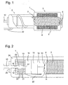
- einen detaillierteren Schnitt durch den Kopfbereich der Linearverdichtereinheit aus
Fig. 1 ; - Fig. 3
- einen Schnitt durch eine zweite Ausgestaltung der Linearverdichtereinheit.
- Fig. 1
- a schematic partial section through a first embodiment of the linear compressor unit according to the invention;
- Fig. 2
- a more detailed section through the head portion of the linear compressor unit
Fig. 1 ; - Fig. 3
- a section through a second embodiment of the linear compressor unit.
Die in
An dem Magneten 4 ist fest ein Kolben 7 montiert, der in eine Arbeitskammer 8 eines Zylinders 9 eingreift und durch die Bewegung des Magneten in dieser verschiebbar ist. An einer dem Kolben 7 gegenüber liegenden Wand der Arbeitskammer 8 sind zwei Öffnungen jeweils mit einem Ventil 10, 11 bestückt. Die Ventile 10, 11 sind hier als Klappen- oder Lamellenventil dargestellt, es versteht sich jedoch, das jeder beliebige Typ von Ventil verwendet werden kann, der einen Durchfluss von Medium nur in eine Richtung - in die Arbeitskammer 8 hinein im Falle des Ventils 10 und aus ihr heraus im Falle des Ventils 11 - zulässt.On the
Zu verdichtendes Medium erreicht die Arbeitskammer 8 über einen Einlassdurchgang 12 in Form eines Rohrstückes, das die Kapsel 1 kreuzt und in dieser fest verankert ist, eine Einlassöffnung 13 des Zylinders 9 und eine Folge von Kammern 14, 15, 16, die im Gehäuse des Zylinders 9 der Arbeitskammer 8 vorgelagert sind.To be compressed medium reaches the
Die Einlassöffnung 13 des Zylinders 9 befindet sich am Ende eines Rohrstutzern 17, der von einer Stirnwand des Zylinders 9 in einer Richtung parallel zur Bewegungsrichtung des Magneten 4 und des Kolbens 7 absteht. Dieser Rohrstutzen 17 liegt einem zweiten Rohrstutzen 18 fluchtend gegenüber, der den ins Innere der Kapsel 1 eingreifenden Teil des Einlassdurchgangs 12 bildet.The
Der Rohrstutzen 18 trägt einen radial abstehenden Flansch 19, an dem eine Mehrzahl von zylindrischen Wänden 20 konzentrisch zur Längsachse des Einlassdurchgangs 12 angeordnet sind. Entsprechende Wände 21 mit passend gestaffelten Durchmessern sind an der Stirnseite des Zylinders 9 angebracht und greifen jeweils zwischen zwei der Wände 20 ein.The
Verdichtetes Medium verlässt die Arbeitskammer 8 über eine Auslassleitung 22, die an einem Ende am Zylinder 9 befestigt ist, schraubenlinienförmig um den Zylinder 9 herum verläuft und schließlich die Wand der Kapsel 1 durchquert. Diese Auslassleitung 22 bildet gleichzeitig eine Aufhängung des Zylinders 9 in der Kapsel 1, die Schwingbewegungen des Zylinders 9, insbesondere in der Längsrichtung, zulässt.Compressed medium leaves the
Im Betrieb der Verdichtereinheit wird mit jeder Bewegung des Kolbens 7 nach links in der Figur in der Arbeitskammer 8 enthaltenes Medium komprimiert und entweicht durch das Auslassventil 11, sobald der Druck in der Arbeitskammer 8 den in der Auslassleitung 22 übersteigt. Dabei übt der Kolben 7 auf den Zylinder 9 einen in der Figur nach links gerichteten Druck aus, dem der Zylinder 9 aufgrund seiner elastischen Aufhängung ein Stück weit nachgeben kann. Bei dieser Bewegung des Kolbens 7 verschieben sich die Wände 20 und 21 gegeneinander, und ein Spalt zwischen dem Ende des Rohrstutzens 18 und der Einlassöffnung 13 des Zylinders 9 verengt sich. Durch diese Beweglichkeit wird eine Übertragung von starken Klopfgeräuschen, die der Kolben 7 an seinem linken Umkehrpunkt verursacht, auf die Kapsel 1 und damit in die Umgebung der Verdichtereinheit vermieden.During operation of the compressor unit, with each movement of the
Wenn anschließend der Kolben 7 vom Magneten 4 nach rechts gezogen wird und die Arbeitskammer 8 sich wieder vergrößert, entsteht in dieser ein Unterdruck, der einerseits dazu führt, dass frisches Medium über den Einlassdurchgang 12 angesaugt wird und andererseits dazu, dass der Zylinder 9 dem Kolben 7 ein Stück weit nach rechts folgt. Die daraus resultierende Verbreiterung des Spalts 23 ist jedoch nicht so groß, dass dadurch die Wände 20, 21 außer Eingriff geraten. Die ineinandergreifende Wände 20, 21 wirken so als ein Drosselelement, das den Abstrom von Medium aus dem Puffervolumen 24 in die Arbeitskammer 8 während der Expansionsphase der Arbeitskammer 8 und entsprechend auch einen Zustrom des Mediums zurück in das Puffervolumen 24 über den Einlassdurchgang 12 in der Kompressionsphase der Arbeitskammer 8 dämpft. So werden auch in dem Fall, dass die Arbeitsfrequenz der Linearverdichtereinheit, d.h. die Schwingfrequenz des Magneten 4, mit der Resonanzfrequenz des Puffervolumen 24 übereinstimmt, Druckschwingüngen des Puffervolumens 24 wirksam gedämpft und ihre Amplitude klein gehalten. So ist eine der Komponenten, die zum Betriebsgeräusch einer Linearverdichtereinheit beitragen, wirksam unterdrückt.Subsequently, when the
Die Kammern 14, 15, 16 des Zylinders 9 haben ebenfalls schalldämpfende Funktionen. Sie sind in an sich aus der Schalldämpfungstechnik bekannter Weise als Helmholtz-Resonatoren ausgeführt.The
Als eine weitere die Betriebsgeräusche der Verdichtereinheit dämpfende Maßnahme ist eine weitere schalldämpfende Kammer 25 in den Einlassdurchgang 12 der Kapsel 1 eingefügt. Diese Kammer 25, von der eine Wand durch die Kapsel 1 selbst gebildet ist, hat eine flachzylindrische Form, wobei der Einlassdurchgang 12 die Kammer 25 entlang ihrer Zylinderachse kreuzt. Auch die Kammer 25 wirkt als ein Helmholtz-Resonator mit einer Eingangsöffnung, die sich über den gesamten Umfang des Einlassdurchgangs 12 erstreckt und daher besonders wirksam ist.As a further measure that dampens the operating noise of the compressor unit, a further sound-damping
Claims (10)
- Linear compressor unit with a magnet (4) reciprocatingly movable in an electromagnetic alternating field, a piston (7) driven by the magnet (4) and movable in a cylinder (9), and a capsule (1) enclosing the cylinder (9) and a reservoir (24), wherein the cylinder (9) is mounted in the capsule (1) to be capable of oscillation and an inlet opening (13) of the cylinder (9) and an inlet passage (12) of the capsule (1) are disposed opposite one another without contact and with formation of a passage (23) to the reservoir (24), characterised in that a throttle element (20, 21) is mounted in the passage (23).
- Linear compressor unit according to claim 1, in which the throttle element is formed by interengaging walls (20, 21) mounted at the capsule (1) or at the cylinder (9).
- Linear compressor unit according to claim 2, in which the walls (20, 21) annularly surround the inlet opening (13) or the inlet passage (12).
- Linear compressor unit according to any one of the preceding claims, in which at least one sound-damping chamber (14, 15, 16) flowed through by the medium to be compressed is arranged between the inlet opening (13) of the cylinder (9) and a chamber (8), which receives the piston (7), of the cylinder (9).
- Linear compressor unit according to any one of the preceding claims, in which at least one sound-damping chamber (25) flowed through by the medium to be compressed is inserted into the inlet passage (12) of the capsule (1).
- Linear compressor unit according to claim 5, in which the chamber (25) is of flat-cylindrical form and the inlet passage (12) extends along the cylinder axis of the chamber (25).
- Linear compressor unit according to any one of the preceding claims, in which the mounting, which is capable of oscillation, of the cylinder (9) is formed by an outlet duct (22) of the cylinder (9).
- Linear compressor unit according to claim 7, in which the outlet duct (22) extends helically around the cylinder (9).
- Linear compressor unit according to any one of the preceding claims, in which the magnet (4) driving the piston (7) is arranged in axial prolongation of the piston (7).
- Linear compressor unit according to any one of claims 1 to 8, in which the magnet (4) driving the piston (7) extends annularly around the piston (7).
Applications Claiming Priority (3)
| Application Number | Priority Date | Filing Date | Title |
|---|---|---|---|
| DE10249215 | 2002-10-22 | ||
| DE10249215A DE10249215A1 (en) | 2002-10-22 | 2002-10-22 | Linear compressor unit |
| PCT/EP2003/011494 WO2004038221A1 (en) | 2002-10-22 | 2003-10-16 | Linear compressor unit |
Publications (2)
| Publication Number | Publication Date |
|---|---|
| EP1556613A1 EP1556613A1 (en) | 2005-07-27 |
| EP1556613B1 true EP1556613B1 (en) | 2009-10-07 |
Family
ID=32102865
Family Applications (1)
| Application Number | Title | Priority Date | Filing Date |
|---|---|---|---|
| EP03758000A Expired - Lifetime EP1556613B1 (en) | 2002-10-22 | 2003-10-16 | Linear compressor unit |
Country Status (11)
| Country | Link |
|---|---|
| US (1) | US7588424B2 (en) |
| EP (1) | EP1556613B1 (en) |
| KR (1) | KR20050059276A (en) |
| CN (1) | CN100507270C (en) |
| AT (1) | ATE445101T1 (en) |
| AU (1) | AU2003274023A1 (en) |
| DE (2) | DE10249215A1 (en) |
| ES (1) | ES2332897T3 (en) |
| PL (1) | PL208290B1 (en) |
| RU (1) | RU2320893C2 (en) |
| WO (1) | WO2004038221A1 (en) |
Families Citing this family (4)
| Publication number | Priority date | Publication date | Assignee | Title |
|---|---|---|---|---|
| AU2008275592A1 (en) * | 2007-07-10 | 2009-01-15 | Tmg Performance Products, Llc | Muffler |
| WO2011015954A1 (en) * | 2009-08-03 | 2011-02-10 | Koninklijke Philips Electronics, N.V. | Low restriction resonator with adjustable frequency characteristics for use in compressor nebulizer systems |
| KR20180092630A (en) | 2017-02-10 | 2018-08-20 | 엘지전자 주식회사 | Linear compressor |
| DE102017107599A1 (en) * | 2017-04-10 | 2018-10-11 | Gardner Denver Deutschland Gmbh | Pulsation silencer for compressors |
Family Cites Families (13)
| Publication number | Priority date | Publication date | Assignee | Title |
|---|---|---|---|---|
| US1496508A (en) * | 1921-05-23 | 1924-06-03 | Yoakum Burt | Boiler blow-off attachment |
| DE2414961A1 (en) * | 1974-03-28 | 1975-10-16 | Heinrich Dipl Ing Doelz | Electrodynamic oscillating plunger compressor for refrigerant - has sound attenuating inlet and outlet chambers in cylinder end wall |
| SE438009B (en) * | 1978-10-03 | 1985-03-25 | Dolmar Maschfab | INSULATION AND / OR EXHAUST SILENCE AT FAST ENGINE COMBUSTION ENGINES |
| US4534861A (en) * | 1984-04-30 | 1985-08-13 | Beckman Instruments, Inc. | Vacuum pump purging apparatus |
| JPH0626448A (en) * | 1991-03-18 | 1994-02-01 | Nissan Motor Co Ltd | Active type pulsation pressure absorber |
| JPH04121477U (en) * | 1991-04-16 | 1992-10-29 | サンデン株式会社 | Free piston type compressor |
| US5355108A (en) * | 1992-10-05 | 1994-10-11 | Aura Systems, Inc. | Electromagnetically actuated compressor valve |
| KR100224186B1 (en) * | 1996-01-16 | 1999-10-15 | 윤종용 | Linear compressorr |
| US5952625A (en) * | 1998-01-20 | 1999-09-14 | Jb Design, Inc. | Multi-fold side branch muffler |
| US6273688B1 (en) * | 1998-10-13 | 2001-08-14 | Matsushita Electric Industrial Co., Ltd. | Linear compressor |
| JP2000161212A (en) | 1998-11-19 | 2000-06-13 | Matsushita Electric Ind Co Ltd | Linear compressor |
| JP3662813B2 (en) * | 1999-08-19 | 2005-06-22 | エルジー電子株式会社 | Linear compressor |
| CN1317074C (en) * | 2003-03-14 | 2007-05-23 | 中国科学院大连化学物理研究所 | Zirconium-base composite oxide catalyst, preparing method and use thereof |
-
2002
- 2002-10-22 DE DE10249215A patent/DE10249215A1/en not_active Withdrawn
-
2003
- 2003-10-16 CN CNB200380101891XA patent/CN100507270C/en not_active Expired - Fee Related
- 2003-10-16 EP EP03758000A patent/EP1556613B1/en not_active Expired - Lifetime
- 2003-10-16 DE DE50312008T patent/DE50312008D1/en not_active Expired - Lifetime
- 2003-10-16 PL PL374602A patent/PL208290B1/en unknown
- 2003-10-16 ES ES03758000T patent/ES2332897T3/en not_active Expired - Lifetime
- 2003-10-16 US US10/531,847 patent/US7588424B2/en not_active Expired - Fee Related
- 2003-10-16 AT AT03758000T patent/ATE445101T1/en not_active IP Right Cessation
- 2003-10-16 AU AU2003274023A patent/AU2003274023A1/en not_active Abandoned
- 2003-10-16 RU RU2005110188/06A patent/RU2320893C2/en not_active IP Right Cessation
- 2003-10-16 WO PCT/EP2003/011494 patent/WO2004038221A1/en not_active Application Discontinuation
- 2003-10-16 KR KR1020057006773A patent/KR20050059276A/en not_active Application Discontinuation
Also Published As
| Publication number | Publication date |
|---|---|
| AU2003274023A1 (en) | 2004-05-13 |
| ES2332897T3 (en) | 2010-02-15 |
| RU2320893C2 (en) | 2008-03-27 |
| CN100507270C (en) | 2009-07-01 |
| US7588424B2 (en) | 2009-09-15 |
| US20060153711A1 (en) | 2006-07-13 |
| DE10249215A1 (en) | 2004-05-13 |
| KR20050059276A (en) | 2005-06-17 |
| PL374602A1 (en) | 2005-10-31 |
| PL208290B1 (en) | 2011-04-29 |
| DE50312008D1 (en) | 2009-11-19 |
| RU2005110188A (en) | 2006-01-20 |
| CN1705824A (en) | 2005-12-07 |
| ATE445101T1 (en) | 2009-10-15 |
| EP1556613A1 (en) | 2005-07-27 |
| WO2004038221A1 (en) | 2004-05-06 |
Similar Documents
| Publication | Publication Date | Title |
|---|---|---|
| EP1828603B1 (en) | Hermetic refrigerant compressor | |
| DE102005005698B4 (en) | linear compressor | |
| DE3714003C2 (en) | Hermetically sealed refrigeration compressor | |
| DE19900886C2 (en) | Structure for coupling a silencer for a linear compressor | |
| EP0551713B1 (en) | Refrigerant compressor discharge muffler | |
| EP1389279A1 (en) | Suction gas guiding system for reciprocating compressor | |
| DE60214196T2 (en) | HERMETIC COMPRESSOR | |
| WO2005073558A1 (en) | Refrigerant compressor | |
| DE69726564T2 (en) | SUCTION ARRANGEMENT FOR A HERMETIC DISPLACEMENT COMPRESSOR | |
| EP1556613B1 (en) | Linear compressor unit | |
| CN101589231A (en) | Reciprocating compressor | |
| DE60312387T2 (en) | MOTORIZED HERMETIC COMPRESSOR AND COOLING DEVICE | |
| DE69723687T3 (en) | SUCTION ARRANGEMENT FOR A HERMETIC DISPLACEMENT COMPRESSOR | |
| KR100624818B1 (en) | Linear compressor | |
| KR20050080657A (en) | Vibration reduction structure of reciprocating compressor | |
| KR20020087241A (en) | A valve plate structure | |
| DE102020213400B4 (en) | COMPRESSOR | |
| DE3308604A1 (en) | RESONANCE ABSORPTION MUFFLER FOR ENGINE COMPRESSORS IN REFRIGERATORS | |
| KR100548273B1 (en) | Device for reducing vibration-noise of reciprocating compressor | |
| DE60223912T2 (en) | OIL FEEDING SYSTEM FOR A HERMETIC COMPRESSOR | |
| KR100323526B1 (en) | Discharge Apparatus of Compressor | |
| EP2225464B1 (en) | Linear compressor assembly | |
| JPH04353277A (en) | Sealed motor driven compressor | |
| KR100550535B1 (en) | Linear compressor | |
| DE102009000424A1 (en) | Compressor for refrigerant, particularly reciprocating compressor of refrigeration cycle of household refrigeration appliance of refrigeration unit, has compressor housing with suction connection, and compression device has suction opening |
Legal Events
| Date | Code | Title | Description |
|---|---|---|---|
| PUAI | Public reference made under article 153(3) epc to a published international application that has entered the european phase |
Free format text: ORIGINAL CODE: 0009012 |
|
| 17P | Request for examination filed |
Effective date: 20050523 |
|
| AK | Designated contracting states |
Kind code of ref document: A1 Designated state(s): AT BE BG CH CY CZ DE DK EE ES FI FR GB GR HU IE IT LI LU MC NL PT RO SE SI SK TR |
|
| AX | Request for extension of the european patent |
Extension state: AL LT LV MK |
|
| DAX | Request for extension of the european patent (deleted) | ||
| 17Q | First examination report despatched |
Effective date: 20060629 |
|
| GRAP | Despatch of communication of intention to grant a patent |
Free format text: ORIGINAL CODE: EPIDOSNIGR1 |
|
| GRAS | Grant fee paid |
Free format text: ORIGINAL CODE: EPIDOSNIGR3 |
|
| GRAA | (expected) grant |
Free format text: ORIGINAL CODE: 0009210 |
|
| AK | Designated contracting states |
Kind code of ref document: B1 Designated state(s): AT BE BG CH CY CZ DE DK EE ES FI FR GB GR HU IE IT LI LU MC NL PT RO SE SI SK TR |
|
| REG | Reference to a national code |
Ref country code: GB Ref legal event code: FG4D Free format text: NOT ENGLISH |
|
| REG | Reference to a national code |
Ref country code: CH Ref legal event code: EP |
|
| REG | Reference to a national code |
Ref country code: IE Ref legal event code: FG4D |
|
| REF | Corresponds to: |
Ref document number: 50312008 Country of ref document: DE Date of ref document: 20091119 Kind code of ref document: P |
|
| REG | Reference to a national code |
Ref country code: ES Ref legal event code: FG2A Ref document number: 2332897 Country of ref document: ES Kind code of ref document: T3 |
|
| PG25 | Lapsed in a contracting state [announced via postgrant information from national office to epo] |
Ref country code: SI Free format text: LAPSE BECAUSE OF FAILURE TO SUBMIT A TRANSLATION OF THE DESCRIPTION OR TO PAY THE FEE WITHIN THE PRESCRIBED TIME-LIMIT Effective date: 20091007 |
|
| NLV1 | Nl: lapsed or annulled due to failure to fulfill the requirements of art. 29p and 29m of the patents act | ||
| BERE | Be: lapsed |
Owner name: BSH BOSCH UND SIEMENS HAUSGERATE G.M.B.H. Effective date: 20091031 |
|
| PG25 | Lapsed in a contracting state [announced via postgrant information from national office to epo] |
Ref country code: PT Free format text: LAPSE BECAUSE OF FAILURE TO SUBMIT A TRANSLATION OF THE DESCRIPTION OR TO PAY THE FEE WITHIN THE PRESCRIBED TIME-LIMIT Effective date: 20100208 Ref country code: FI Free format text: LAPSE BECAUSE OF FAILURE TO SUBMIT A TRANSLATION OF THE DESCRIPTION OR TO PAY THE FEE WITHIN THE PRESCRIBED TIME-LIMIT Effective date: 20091007 Ref country code: SE Free format text: LAPSE BECAUSE OF FAILURE TO SUBMIT A TRANSLATION OF THE DESCRIPTION OR TO PAY THE FEE WITHIN THE PRESCRIBED TIME-LIMIT Effective date: 20091007 |
|
| REG | Reference to a national code |
Ref country code: IE Ref legal event code: FD4D |
|
| PG25 | Lapsed in a contracting state [announced via postgrant information from national office to epo] |
Ref country code: MC Free format text: LAPSE BECAUSE OF NON-PAYMENT OF DUE FEES Effective date: 20091031 |
|
| REG | Reference to a national code |
Ref country code: CH Ref legal event code: PL |
|
| PG25 | Lapsed in a contracting state [announced via postgrant information from national office to epo] |
Ref country code: EE Free format text: LAPSE BECAUSE OF FAILURE TO SUBMIT A TRANSLATION OF THE DESCRIPTION OR TO PAY THE FEE WITHIN THE PRESCRIBED TIME-LIMIT Effective date: 20091007 Ref country code: RO Free format text: LAPSE BECAUSE OF FAILURE TO SUBMIT A TRANSLATION OF THE DESCRIPTION OR TO PAY THE FEE WITHIN THE PRESCRIBED TIME-LIMIT Effective date: 20091007 Ref country code: BG Free format text: LAPSE BECAUSE OF FAILURE TO SUBMIT A TRANSLATION OF THE DESCRIPTION OR TO PAY THE FEE WITHIN THE PRESCRIBED TIME-LIMIT Effective date: 20100107 Ref country code: NL Free format text: LAPSE BECAUSE OF FAILURE TO SUBMIT A TRANSLATION OF THE DESCRIPTION OR TO PAY THE FEE WITHIN THE PRESCRIBED TIME-LIMIT Effective date: 20091007 Ref country code: DK Free format text: LAPSE BECAUSE OF FAILURE TO SUBMIT A TRANSLATION OF THE DESCRIPTION OR TO PAY THE FEE WITHIN THE PRESCRIBED TIME-LIMIT Effective date: 20091007 Ref country code: IE Free format text: LAPSE BECAUSE OF FAILURE TO SUBMIT A TRANSLATION OF THE DESCRIPTION OR TO PAY THE FEE WITHIN THE PRESCRIBED TIME-LIMIT Effective date: 20091007 |
|
| PLBE | No opposition filed within time limit |
Free format text: ORIGINAL CODE: 0009261 |
|
| STAA | Information on the status of an ep patent application or granted ep patent |
Free format text: STATUS: NO OPPOSITION FILED WITHIN TIME LIMIT |
|
| PG25 | Lapsed in a contracting state [announced via postgrant information from national office to epo] |
Ref country code: CZ Free format text: LAPSE BECAUSE OF FAILURE TO SUBMIT A TRANSLATION OF THE DESCRIPTION OR TO PAY THE FEE WITHIN THE PRESCRIBED TIME-LIMIT Effective date: 20091007 Ref country code: SK Free format text: LAPSE BECAUSE OF FAILURE TO SUBMIT A TRANSLATION OF THE DESCRIPTION OR TO PAY THE FEE WITHIN THE PRESCRIBED TIME-LIMIT Effective date: 20091007 |
|
| 26N | No opposition filed |
Effective date: 20100708 |
|
| PG25 | Lapsed in a contracting state [announced via postgrant information from national office to epo] |
Ref country code: BE Free format text: LAPSE BECAUSE OF NON-PAYMENT OF DUE FEES Effective date: 20091031 Ref country code: LI Free format text: LAPSE BECAUSE OF NON-PAYMENT OF DUE FEES Effective date: 20091031 Ref country code: GR Free format text: LAPSE BECAUSE OF FAILURE TO SUBMIT A TRANSLATION OF THE DESCRIPTION OR TO PAY THE FEE WITHIN THE PRESCRIBED TIME-LIMIT Effective date: 20100108 Ref country code: CH Free format text: LAPSE BECAUSE OF NON-PAYMENT OF DUE FEES Effective date: 20091031 |
|
| PG25 | Lapsed in a contracting state [announced via postgrant information from national office to epo] |
Ref country code: AT Free format text: LAPSE BECAUSE OF NON-PAYMENT OF DUE FEES Effective date: 20091016 |
|
| PG25 | Lapsed in a contracting state [announced via postgrant information from national office to epo] |
Ref country code: LU Free format text: LAPSE BECAUSE OF NON-PAYMENT OF DUE FEES Effective date: 20091016 |
|
| PG25 | Lapsed in a contracting state [announced via postgrant information from national office to epo] |
Ref country code: HU Free format text: LAPSE BECAUSE OF FAILURE TO SUBMIT A TRANSLATION OF THE DESCRIPTION OR TO PAY THE FEE WITHIN THE PRESCRIBED TIME-LIMIT Effective date: 20100408 |
|
| PG25 | Lapsed in a contracting state [announced via postgrant information from national office to epo] |
Ref country code: CY Free format text: LAPSE BECAUSE OF FAILURE TO SUBMIT A TRANSLATION OF THE DESCRIPTION OR TO PAY THE FEE WITHIN THE PRESCRIBED TIME-LIMIT Effective date: 20091007 |
|
| PGFP | Annual fee paid to national office [announced via postgrant information from national office to epo] |
Ref country code: FR Payment date: 20131018 Year of fee payment: 11 Ref country code: DE Payment date: 20131031 Year of fee payment: 11 Ref country code: GB Payment date: 20131022 Year of fee payment: 11 |
|
| PGFP | Annual fee paid to national office [announced via postgrant information from national office to epo] |
Ref country code: IT Payment date: 20131029 Year of fee payment: 11 Ref country code: ES Payment date: 20131022 Year of fee payment: 11 |
|
| PGFP | Annual fee paid to national office [announced via postgrant information from national office to epo] |
Ref country code: TR Payment date: 20141009 Year of fee payment: 12 |
|
| REG | Reference to a national code |
Ref country code: DE Ref legal event code: R119 Ref document number: 50312008 Country of ref document: DE |
|
| GBPC | Gb: european patent ceased through non-payment of renewal fee |
Effective date: 20141016 |
|
| PG25 | Lapsed in a contracting state [announced via postgrant information from national office to epo] |
Ref country code: GB Free format text: LAPSE BECAUSE OF NON-PAYMENT OF DUE FEES Effective date: 20141016 Ref country code: DE Free format text: LAPSE BECAUSE OF NON-PAYMENT OF DUE FEES Effective date: 20150501 |
|
| REG | Reference to a national code |
Ref country code: FR Ref legal event code: ST Effective date: 20150630 |
|
| PG25 | Lapsed in a contracting state [announced via postgrant information from national office to epo] |
Ref country code: FR Free format text: LAPSE BECAUSE OF NON-PAYMENT OF DUE FEES Effective date: 20141031 Ref country code: IT Free format text: LAPSE BECAUSE OF NON-PAYMENT OF DUE FEES Effective date: 20141016 |
|
| REG | Reference to a national code |
Ref country code: ES Ref legal event code: FD2A Effective date: 20151126 |
|
| PG25 | Lapsed in a contracting state [announced via postgrant information from national office to epo] |
Ref country code: ES Free format text: LAPSE BECAUSE OF NON-PAYMENT OF DUE FEES Effective date: 20141017 |
|
| PG25 | Lapsed in a contracting state [announced via postgrant information from national office to epo] |
Ref country code: TR Free format text: LAPSE BECAUSE OF NON-PAYMENT OF DUE FEES Effective date: 20151016 |