EP1556171B1 - Aerosol generating devices and methods for generating aerosols having controlled particle sizes - Google Patents
Aerosol generating devices and methods for generating aerosols having controlled particle sizes Download PDFInfo
- Publication number
- EP1556171B1 EP1556171B1 EP03752007A EP03752007A EP1556171B1 EP 1556171 B1 EP1556171 B1 EP 1556171B1 EP 03752007 A EP03752007 A EP 03752007A EP 03752007 A EP03752007 A EP 03752007A EP 1556171 B1 EP1556171 B1 EP 1556171B1
- Authority
- EP
- European Patent Office
- Prior art keywords
- aerosol
- generating device
- flow passage
- confinement sleeve
- inch
- Prior art date
- Legal status (The legal status is an assumption and is not a legal conclusion. Google has not performed a legal analysis and makes no representation as to the accuracy of the status listed.)
- Expired - Lifetime
Links
- 239000000443 aerosol Substances 0.000 title claims abstract description 392
- 239000002245 particle Substances 0.000 title claims description 122
- 238000000034 method Methods 0.000 title claims description 13
- 239000007788 liquid Substances 0.000 claims abstract description 48
- 239000003814 drug Substances 0.000 claims description 30
- 230000001965 increasing effect Effects 0.000 claims description 14
- 238000010438 heat treatment Methods 0.000 claims description 13
- 230000003247 decreasing effect Effects 0.000 claims description 5
- 239000012530 fluid Substances 0.000 claims description 5
- 229940124630 bronchodilator Drugs 0.000 claims description 4
- 239000000168 bronchodilator agent Substances 0.000 claims description 4
- 229940035676 analgesics Drugs 0.000 claims description 3
- 230000000954 anitussive effect Effects 0.000 claims description 3
- 239000000730 antalgic agent Substances 0.000 claims description 3
- 239000003242 anti bacterial agent Substances 0.000 claims description 3
- 230000003266 anti-allergic effect Effects 0.000 claims description 3
- 239000000043 antiallergic agent Substances 0.000 claims description 3
- 229940088710 antibiotic agent Drugs 0.000 claims description 3
- 229940065524 anticholinergics inhalants for obstructive airway diseases Drugs 0.000 claims description 3
- 229940125715 antihistaminic agent Drugs 0.000 claims description 3
- 239000000739 antihistaminic agent Substances 0.000 claims description 3
- 239000003434 antitussive agent Substances 0.000 claims description 3
- 229940124584 antitussives Drugs 0.000 claims description 3
- 239000003795 chemical substances by application Substances 0.000 claims description 3
- 239000000812 cholinergic antagonist Substances 0.000 claims description 3
- IZEKFCXSFNUWAM-UHFFFAOYSA-N dipyridamole Chemical compound C=12N=C(N(CCO)CCO)N=C(N3CCCCC3)C2=NC(N(CCO)CCO)=NC=1N1CCCCC1 IZEKFCXSFNUWAM-UHFFFAOYSA-N 0.000 claims description 3
- 239000002934 diuretic Substances 0.000 claims description 3
- 229940030606 diuretics Drugs 0.000 claims description 3
- 229940088597 hormone Drugs 0.000 claims description 3
- 239000005556 hormone Substances 0.000 claims description 3
- 239000011810 insulating material Substances 0.000 claims description 3
- 238000002360 preparation method Methods 0.000 claims description 3
- 238000004891 communication Methods 0.000 claims description 2
- 239000012777 electrically insulating material Substances 0.000 claims description 2
- 239000000126 substance Substances 0.000 claims description 2
- 238000009826 distribution Methods 0.000 abstract description 38
- DNIAPMSPPWPWGF-UHFFFAOYSA-N Propylene glycol Chemical compound CC(O)CO DNIAPMSPPWPWGF-UHFFFAOYSA-N 0.000 description 339
- ALSTYHKOOCGGFT-KTKRTIGZSA-N (9Z)-octadecen-1-ol Chemical compound CCCCCCCC\C=C/CCCCCCCCO ALSTYHKOOCGGFT-KTKRTIGZSA-N 0.000 description 40
- 229940055577 oleyl alcohol Drugs 0.000 description 40
- XMLQWXUVTXCDDL-UHFFFAOYSA-N oleyl alcohol Natural products CCCCCCC=CCCCCCCCCCCO XMLQWXUVTXCDDL-UHFFFAOYSA-N 0.000 description 40
- 238000011084 recovery Methods 0.000 description 40
- 239000003570 air Substances 0.000 description 36
- 239000000243 solution Substances 0.000 description 23
- NDAUXUAQIAJITI-UHFFFAOYSA-N albuterol Chemical compound CC(C)(C)NCC(O)C1=CC=C(O)C(CO)=C1 NDAUXUAQIAJITI-UHFFFAOYSA-N 0.000 description 18
- 229960002052 salbutamol Drugs 0.000 description 18
- URAYPUMNDPQOKB-UHFFFAOYSA-N triacetin Chemical compound CC(=O)OCC(OC(C)=O)COC(C)=O URAYPUMNDPQOKB-UHFFFAOYSA-N 0.000 description 18
- 239000000203 mixture Substances 0.000 description 12
- 230000000694 effects Effects 0.000 description 11
- 239000000463 material Substances 0.000 description 11
- 238000009472 formulation Methods 0.000 description 10
- 235000013773 glyceryl triacetate Nutrition 0.000 description 9
- 239000001087 glyceryl triacetate Substances 0.000 description 9
- 229960002622 triacetin Drugs 0.000 description 9
- 239000008263 liquid aerosol Substances 0.000 description 7
- 210000004072 lung Anatomy 0.000 description 7
- 238000000151 deposition Methods 0.000 description 6
- 230000008021 deposition Effects 0.000 description 5
- 210000002345 respiratory system Anatomy 0.000 description 5
- VOVIALXJUBGFJZ-KWVAZRHASA-N Budesonide Chemical compound C1CC2=CC(=O)C=C[C@]2(C)[C@@H]2[C@@H]1[C@@H]1C[C@H]3OC(CCC)O[C@@]3(C(=O)CO)[C@@]1(C)C[C@@H]2O VOVIALXJUBGFJZ-KWVAZRHASA-N 0.000 description 4
- 229920002565 Polyethylene Glycol 400 Polymers 0.000 description 4
- 229960004436 budesonide Drugs 0.000 description 4
- BASFCYQUMIYNBI-UHFFFAOYSA-N platinum Chemical compound [Pt] BASFCYQUMIYNBI-UHFFFAOYSA-N 0.000 description 4
- 229910052751 metal Inorganic materials 0.000 description 3
- 239000002184 metal Substances 0.000 description 3
- 238000002156 mixing Methods 0.000 description 3
- 239000003973 paint Substances 0.000 description 3
- 230000035515 penetration Effects 0.000 description 3
- 239000000843 powder Substances 0.000 description 3
- 239000003380 propellant Substances 0.000 description 3
- 239000007921 spray Substances 0.000 description 3
- IJGRMHOSHXDMSA-UHFFFAOYSA-N Atomic nitrogen Chemical compound N#N IJGRMHOSHXDMSA-UHFFFAOYSA-N 0.000 description 2
- 239000012080 ambient air Substances 0.000 description 2
- 239000000919 ceramic Substances 0.000 description 2
- 230000000052 comparative effect Effects 0.000 description 2
- 239000004020 conductor Substances 0.000 description 2
- 238000010790 dilution Methods 0.000 description 2
- 239000012895 dilution Substances 0.000 description 2
- 230000004907 flux Effects 0.000 description 2
- 239000011521 glass Substances 0.000 description 2
- 239000003102 growth factor Substances 0.000 description 2
- 230000001939 inductive effect Effects 0.000 description 2
- 229910052697 platinum Inorganic materials 0.000 description 2
- 229920000642 polymer Polymers 0.000 description 2
- 229910001220 stainless steel Inorganic materials 0.000 description 2
- 239000010935 stainless steel Substances 0.000 description 2
- 239000002202 Polyethylene glycol Substances 0.000 description 1
- 208000006673 asthma Diseases 0.000 description 1
- 230000015572 biosynthetic process Effects 0.000 description 1
- 239000002775 capsule Substances 0.000 description 1
- 238000000576 coating method Methods 0.000 description 1
- 239000002131 composite material Substances 0.000 description 1
- 238000009833 condensation Methods 0.000 description 1
- 230000005494 condensation Effects 0.000 description 1
- 238000010276 construction Methods 0.000 description 1
- 238000001816 cooling Methods 0.000 description 1
- 230000007423 decrease Effects 0.000 description 1
- 230000000881 depressing effect Effects 0.000 description 1
- 238000001514 detection method Methods 0.000 description 1
- 229940079593 drug Drugs 0.000 description 1
- 239000000446 fuel Substances 0.000 description 1
- 239000007789 gas Substances 0.000 description 1
- 239000011261 inert gas Substances 0.000 description 1
- 239000011344 liquid material Substances 0.000 description 1
- 239000000314 lubricant Substances 0.000 description 1
- 238000004519 manufacturing process Methods 0.000 description 1
- 238000004377 microelectronic Methods 0.000 description 1
- 229910052757 nitrogen Inorganic materials 0.000 description 1
- 210000003800 pharynx Anatomy 0.000 description 1
- 239000004033 plastic Substances 0.000 description 1
- 229920003023 plastic Polymers 0.000 description 1
- 229920001223 polyethylene glycol Polymers 0.000 description 1
- 230000002685 pulmonary effect Effects 0.000 description 1
- 230000000241 respiratory effect Effects 0.000 description 1
- -1 scents Substances 0.000 description 1
- 239000007787 solid Substances 0.000 description 1
- 239000000725 suspension Substances 0.000 description 1
- 238000011144 upstream manufacturing Methods 0.000 description 1
- XLYOFNOQVPJJNP-UHFFFAOYSA-N water Substances O XLYOFNOQVPJJNP-UHFFFAOYSA-N 0.000 description 1
Images


Classifications
-
- B—PERFORMING OPERATIONS; TRANSPORTING
- B05—SPRAYING OR ATOMISING IN GENERAL; APPLYING FLUENT MATERIALS TO SURFACES, IN GENERAL
- B05B—SPRAYING APPARATUS; ATOMISING APPARATUS; NOZZLES
- B05B1/00—Nozzles, spray heads or other outlets, with or without auxiliary devices such as valves, heating means
- B05B1/24—Nozzles, spray heads or other outlets, with or without auxiliary devices such as valves, heating means incorporating means for heating the liquid or other fluent material, e.g. electrically
-
- A—HUMAN NECESSITIES
- A61—MEDICAL OR VETERINARY SCIENCE; HYGIENE
- A61M—DEVICES FOR INTRODUCING MEDIA INTO, OR ONTO, THE BODY; DEVICES FOR TRANSDUCING BODY MEDIA OR FOR TAKING MEDIA FROM THE BODY; DEVICES FOR PRODUCING OR ENDING SLEEP OR STUPOR
- A61M11/00—Sprayers or atomisers specially adapted for therapeutic purposes
- A61M11/001—Particle size control
- A61M11/002—Particle size control by flow deviation causing inertial separation of transported particles
-
- A—HUMAN NECESSITIES
- A61—MEDICAL OR VETERINARY SCIENCE; HYGIENE
- A61M—DEVICES FOR INTRODUCING MEDIA INTO, OR ONTO, THE BODY; DEVICES FOR TRANSDUCING BODY MEDIA OR FOR TAKING MEDIA FROM THE BODY; DEVICES FOR PRODUCING OR ENDING SLEEP OR STUPOR
- A61M11/00—Sprayers or atomisers specially adapted for therapeutic purposes
- A61M11/04—Sprayers or atomisers specially adapted for therapeutic purposes operated by the vapour pressure of the liquid to be sprayed or atomised
- A61M11/041—Sprayers or atomisers specially adapted for therapeutic purposes operated by the vapour pressure of the liquid to be sprayed or atomised using heaters
- A61M11/042—Sprayers or atomisers specially adapted for therapeutic purposes operated by the vapour pressure of the liquid to be sprayed or atomised using heaters electrical
-
- B—PERFORMING OPERATIONS; TRANSPORTING
- B05—SPRAYING OR ATOMISING IN GENERAL; APPLYING FLUENT MATERIALS TO SURFACES, IN GENERAL
- B05B—SPRAYING APPARATUS; ATOMISING APPARATUS; NOZZLES
- B05B7/00—Spraying apparatus for discharge of liquids or other fluent materials from two or more sources, e.g. of liquid and air, of powder and gas
- B05B7/0012—Apparatus for achieving spraying before discharge from the apparatus
-
- A—HUMAN NECESSITIES
- A61—MEDICAL OR VETERINARY SCIENCE; HYGIENE
- A61M—DEVICES FOR INTRODUCING MEDIA INTO, OR ONTO, THE BODY; DEVICES FOR TRANSDUCING BODY MEDIA OR FOR TAKING MEDIA FROM THE BODY; DEVICES FOR PRODUCING OR ENDING SLEEP OR STUPOR
- A61M15/00—Inhalators
-
- A—HUMAN NECESSITIES
- A61—MEDICAL OR VETERINARY SCIENCE; HYGIENE
- A61M—DEVICES FOR INTRODUCING MEDIA INTO, OR ONTO, THE BODY; DEVICES FOR TRANSDUCING BODY MEDIA OR FOR TAKING MEDIA FROM THE BODY; DEVICES FOR PRODUCING OR ENDING SLEEP OR STUPOR
- A61M2205/00—General characteristics of the apparatus
- A61M2205/50—General characteristics of the apparatus with microprocessors or computers
Definitions
- Aerosols are useful in a wide variety of applications.
- aerosols have been used to treat respiratory ailments, or to deliver medicaments, by providing sprays of finely divided particles of liquids and/or solids, such as powders, liquid medicaments, and the like, which are inhaled by patients.
- Aerosols are also useful, for example, for delivering desired scents to rooms, applying scents to the skin, and delivering paints and lubricants.
- U.S. Patents Nos. 4,811,731 and 4,627,432 disclose devices for administrating medicaments to patients that include a capsule, which is pierced to release medicament in powder form. The user inhales the released medicament through an opening in the device. Medicaments in liquid form have been delivered by generating aerosols with a manually operated pump. The pump draws liquid from a reservoir and forces it through a small opening to form a fine spray.
- medicaments have been delivered by generating an aerosol including liquid or powder particles using a compressed propellant, which entrains the medicament.
- Such inhalers are usually operated by depressing an actuator to release a charge of the compressed propellant, which contains the medicament, through a spray nozzle, allowing the propellant encapsulated medicament to be inhaled by the user.
- US 2002/0079309 discloses a capillary aerosol generator including two heating zones according to the preamble of claim 1. Fluid is vaporised as it passes through the second heating zone and forms an aerosol as it exits from the outlet of the generator.
- Aerosol generating devices also are unable to generate aerosols having an average mass median aerosol diameter (MMAD) less than 2 to 4 microns, and to deliver high aerosol mass flow rates, such as above 1 milligram per second, with particles in the size range of 0.2 to 2.0 microns.
- MMAD average mass median aerosol diameter
- a high aerosol mass flow rate and small particle size are particularly desirable for enhanced penetration into the lungs during medicament administration, such as for asthma treatment.
- an aerosol generating device that can provide different aerosol size distributions of aerosols, such that the device can be adapted to the different needs of a patient. Moreover, there is a need for an aerosol generating device that provides controlled adjustability of the aerosol size distribution of aerosols that it produces.
- An aerosol generating device that can produce aerosols having different aerosol size distributions.
- the aerosol generating device provides controlled adjustability of the aerosol size distribution, such that it can be used to provide aerosols that are most suitable to meet the needs of a user.
- the aerosol generating device comprises, a flow passage, a heater, and an aerosol confinement sleeve. Liquid is supplied into the flow passage from the source and heated in the flow passage by the heater, thereby volatilizing the liquid.
- the aerosol confinement sleeve is disposed about the outlet end of the flow passage. Volatilized material exiting the flow passage enters into the aerosol confinement sleeve, which is configured to control the aerosol size distribution delivered by the aerosol generating device. At least one of the length L and maximum diameter W of the aerosol confinement sleeve may be varied to control the MMAD of the aerosol particles delivered by the device during use.
- a method for generating an aerosol comprising supplying a liquid to a flow passage; heating the liquid in the flow passage to volatilize the liquid; and admixing the volatilized liquid with air to produce an aerosol; and passing the volatilized liquid is directed out of the flow passage and into an aerosol confinement sleeve configured to control an aerosol size distribution of an aerosol produced from the volatilized liquid.
- the MMAD of the particles of the produced aerosol is controlled by controlling the length L and maximum diameter W of the aerosol confinement sleeve.
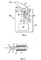
- Figure 1 illustrates an embodiment of an aerosol generating device.
- Figure 2 illustrates an embodiment of an arrangement including an aerosol confinement sleeve located at the outlet end of a flow passage.
- Figure 3 shows the relationship between the mass median aerodynamic diameter (MMAD) of propylene glycol (PG) and the aerosol confinement sleeve length.
- Figure 4 shows the relationship between the percentage PG recovery and the aerosol confinement sleeve length.
- Figure 5 shows the relationship between the MMAD of PG aerosol particles and the air flow rate (inhalation rate) for two different sized capillary passages.
- Figure 6 illustrates the relationship between aerosol particle diameter and PG flow rate in the flow passage for aerosols produced using different sized flow passages.
- Figure 7 shows the size distributions of aerosol particles of PG and oleyl alcohol (OA) in an aerosol produced from a solution of OA in PG.
- Figure 8 shows the MMAD of aerosol particles of PG and OA in aerosols produced from solutions having different concentrations of OA in PG.
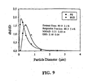
- Figure 9 shows the size distribution of aerosol particles of budesonide and PG in an aerosol produced from a solution of budesonide in PG.
- Figure 10 shows the size distribution of aerosol particles of PEG 400 and PG in an aerosol produced from a solution of PEG 400 in PG.
- Figure 11 shows relationships between the MMAD of PG aerosol particles and aerosol confinement sleeve length (Curve A), and between percent PG recovery and aerosol confinement sleeve length (Curve B) for a mouthpiece having an inner diameter of 32 mm (1.25 inch.)
- Figure 12 shows relationships between the MMAD of PG aerosol particles and aerosol confinement sleeve length (Curve A), and between percent PG recovery and aerosol confinement sleeve length (Curve B) for a mouthpiece having an inner diameter of 22 mm (7/8 inch.)
- Figure 13 shows approximated air streamlines generated with mouthpieces having an inner diameter of 32 mm (1.25 inch) (A) and 22 mm (7/8 inch) (B).
- Figure 14 shows the relationship between the MMAD of PG aerosol particles and aerosol confinement sleeve length for mouthpieces having an inner diameter of 32 mm (1.25 inch) and 22 mm (7/8) inch.
- Figure 15 shows relationships between the MMAD of PG aerosol particles and air flow rate (Curve A), and between percent PG recovery and air flow rate (Curve B) for a mouthpiece having an inner diameter of 19 mm (3/4 inch.)
- Figure 16 shows relationships between the MMAD of PG aerosol particles and aerosol confinement sleeve length (Curve A), and between percent PG recovery and aerosol confinement sleeve length (Curve B) for an aerosol confinement sleeve having an inner diameter of 10 mm (3/8 inch) for a PG flow rate of 10 mg/sec.
- Figure 17 shows relationships between the MMAD of PG aerosol particles and aerosol confinement sleeve length (Curve A), and between percent PG recovery and aerosol confinement sleeve length (Curve B), for an aerosol confinement sleeve having an inner diameter of 10 mm (3/8 inch) and a PG flow rate of 5 mg/sec.
- Figure 18 shows relationships between the MMAD of PG aerosol particles and aerosol confinement sleeve length (Curve A), and between percent PG recovery and aerosol confinement sleeve length (Curve B) for an aerosol confinement sleeve having an inner diameter of 6 mm (1/4 inch) and at a PG flow rate of 10 mg/sec.
- Figure 19 shows size distributions for PG aerosol particles (Curve C) and albuterol aerosol particles (Curve D) produced with a 1% w/w albuterol in PG solution with an aerosol confinement sleeve, and for PG aerosol particles (Curve A) and albuterol aerosol particles (Curve B) produced without the aerosol confinement sleeve.
- Figure 20 shows PG total aerosol particle size distributions produced with a 0.5 % w/w albuterol in PG solution without an aerosol confinement sleeve (Curve A), and produced with an aerosol confinement sleeve having a length of 25 mm (1 inch) (Curve B), 32 mm (1.25 inch) (Curve C), and 38 mm (1.5 inch) (Curve D).
- Figure 21 shows albuterol aerosol particle size distributions produced with a 0.5% w/w albuterol in PG solution without an aerosol confinement sleeve (Curve A), and produced with an aerosol confinement sleeve having a length of 1 inch (Curve B), 32 mm (1.25 inch) (Curve C), and 38 mm (1.5 inch) (Curve D).
- Figure 22 shows relationships between triacetin aerosol particle size and aerosol confinement sleeve length (Curve A), and between triacetin recovery and aerosol confinement sleeve length (Curve B) for an aerosol confinement sleeve having an inner diameter of 13 mm (0.5 inch.)
- Figure 23 shows relationships between the MMAD of OA aerosol particles and aerosol confinement sleeve length (Curve A), and between percent PG recovery and aerosol confinement sleeve length (Curve B) for a 5% w/w OA in PG solution and using an aerosol confinement sleeve having a 13 mm (1 ⁇ 2 inch) inner diameter.
- Figure 24 shows relationships between the MMAD of PG aerosol particles and aerosol confinement sleeve length (Curve A), and between PG recovery and aerosol confinement sleeve length (Curve B) for a 5% w/w OA in PG solution with an aerosol confinement sleeve having a 13 mm (1 ⁇ 2 inch) inner diameter.
- Figure 25 shows the aerosol particle distribution for OA produced without an aerosol confinement sleeve (Curve A), and produced with an aerosol confinement sleeve having a length of 19 mm (0.75 inch) (Curve B), 25 mm (1 inch) (Curve C), 32 mm (1.25 inch) (Curve D), and 38 mm (1.5 inch) (Curve E).
- Figure 26 shows the relationship between the MMAD of OA aerosol particles and air flow rate for a 5% w/w OA in PG solution.
- Figure 27 shows the relationship between the MMAD of PG aerosol particles and air flow rate for a 5% w/w OA in PG solution.
- An aerosol generating device which can be operated to produce aerosols having a controlled particle size distribution.
- the aerosol generating device includes an aerosol confinement sleeve, which controls the particle size distribution of aerosols.
- the aerosol generating device includes a replaceable aerosol confinement sleeve, which permits a user or manufacturer to change the aerosol confinement sleeve to provide a different aerosol particle size distribution.
- FIG. 1 depicts a preferred embodiment of a hand-held aerosol generating device 120.
- the aerosol generating device 120 comprises a housing 121, a source 122 of a liquid aerosol formulation, a controller 124, a power source 126, an optional sensor 127, such as a pressure sensor, a heated flow passage 128, a valve 130, and a mouthpiece 132.
- the valve 130 is operable to deliver a volume of fluid, such as a predetermined dose, from the source 122 to the flow passage 128.
- the controller 124 is operably connected to the power source 126, the sensor 127 and valve 130 to effect delivery of the liquid from the source 122 to the flow passage 128, and to operate a heater arranged to heat liquid in the flow passage 128.
- the flow passage comprises a capillary sized flow passage.
- the capillary sized flow passage can be tube or alternatively a passage in a body, such as a monolithic or multilayer body of an electrically insulating material.
- the heated flow passage 128 comprises an electrically conductive material, such as a metallic tube (e.g., stainless steel), or a non-conductive or semi-conductive tube incorporating a heater made of an electrically conductive material, such as platinum, or the like.
- the flow passage is preferably a capillary sized passage of uniform cross-section along its length.
- the flow passage can have any suitable diameter, preferably between about 0.1 to 10 mm, more preferably about 0.1 to 1 mm, and most preferably about 0.15 to 0.5 mm.
- the capillary passage can have other non-uniform cross-sectional configurations, which are defined by a maximum transverse dimension or width, or by a transverse cross-sectional area.
- the capillary passage can have a transverse cross-sectional area from about 8 x 10 -5 mm 2 to about 80 mm 2 , preferably about 2 x 10 -3 mm 2 to about 8 x 10 -1 mm 2 , and more preferably about 8 x 10 -3 mm 2 to about 2 x 10 -1 mm 2 .
- the flow passage 128 may be configured to extend in a linear or non-linear direction. As shown in Figures 1 and 2 , a portion of the flow passage 128 is disposed within a body 129.
- the flow passage 128 comprises a section of tubing supported coaxially within the body 129.
- the body 129 has an inner transverse dimension or width larger than the tubing forming the flow passage.
- a rear wall 134 of the body 129 forms a seal about the outer surface of the tube defining the flow passage 128 to form a dead air space 135 between the tube defining the flow passage 128 and the body 129.
- the body 129 is preferably air impermeable.
- the body 129 can have various shapes, such as cylindrical, oval, polygonal, or conical.
- the body can be any suitable material, such as a metal, ceramic, polymer, glass, or a mixture or composite thereof.
- the body is made of a thermally insulating material to minimize loss of heat of air within the space 135 and thereby minimize heat loss from the tube defining the flow passage 128. By minimizing heat loss from the flow passage, it is possible to reduce the time needed to heat the flow passage to a desired temperature to vaporize liquid in the flow passage, and/or to heat the flow passage to a more uniform temperature.
- the flow passage can be heated by passing electrical current through a heater comprising a resistive heating material, such as a section of metal tubing forming the flow passage, or a separate heater can be located along the flow passage.
- a heater comprising a resistive heating material, such as a section of metal tubing forming the flow passage, or a separate heater can be located along the flow passage.
- direct current can be passed through resistive heating material via electrical lines 126a, 126b attached to positive and negative electrodes of battery 126.
- an aerosol confinement sleeve 140 is provided about the body 129 and flow passage 128. As described in detail below, the aerosol confinement sleeve 140 controls the aerosol particle size of aerosols delivered by the aerosol generating device 120.
- the aerosol generating device 120 when the controller 124 activates the power supply to pass electrical current through the heater formed by the resistive heating material, liquid in the flow passage 128 is heated to a sufficient temperature to be vaporized.
- the aerosol generating device 120 includes a power supply, which supplies electric current to the heater formed by a portion of a metallic tube, such as a stainless steel tube, between electrical contacts (not shown) on the tube to which lines 126a and 126b are attached.
- a power supply which supplies electric current to the heater formed by a portion of a metallic tube, such as a stainless steel tube, between electrical contacts (not shown) on the tube to which lines 126a and 126b are attached.
- power can be supplied by an external power source.
- the controller 124 is programmed to activate the power supply in an intermittent manner so as to heat the flow passage 128 for a predetermined time interval during which a predetermined volume of fluid is supplied to the flow passage 128 from the source 122.
- a preferred embodiment comprises a laminate body including opposed layers bonded together, and a flow passage disposed between the layers, as described in commonly-assigned U.S. Application Serial No. 09/742,320 filed December 22, 2000 , the disclosure of which is hereby incorporated by reference in its entirety.
- an inductive heating arrangement can be used, such as the arrangement disclosed in commonly-assigned U.S. Application Serial No. 09/742,323 filed on December 22, 2000 , the disclosure of which is hereby incorporated by reference in its entirety.
- a current is passed through one or more inductive heating coils to produce an electromagnetic flux in an electrically conductive heating element, which is located such that the flux produces eddy currents inside the heating element, which in turn heats the heating element. This heat is then transferred to the liquid within the flow passage 128 either by direct or indirect thermal conduction.
- the heating arrangement includes a resistance heater, such as a thin platinum layer, located along the flow passage, as described in commonly-assigned U.S. Patent Nos. 5,743,251 and 6,234,167 , each of which is hereby incorporated by reference in its entirety.
- a resistance heater such as a thin platinum layer
- the mouthpiece 132 has a volumetric capacity of from about 5 cm 3 to about 10 cm 3 .
- the mouthpiece 132 includes a mouthpiece opening 132a through which aerosol generated by the aerosol generating device 120 exits to a patient inhaling the aerosol.
- the aerosol generating device 120 can include one or more air passages 136 to permit the passage of external air into the aerosol generating device 120.
- the external air passes into the interior space 132b defined by the mouthpiece 132.
- the external air inside the mouthpiece 132 admixes with the volatilized liquid exiting the heated flow passage 128 within the mouthpiece 132.
- the mouthpiece opening 132a is separated from the outlet end of the heated flow passage 128 so that air passing into the space 132b admixes with the volatilized liquid prior to exiting through the mouthpiece opening 132a.
- gases e.g:, inert gases, nitrogen, or the like
- suitable for dilution of medicament within the aerosol generating device may be mixed with the volatilized fluid exiting the heated flow passage 128.
- the valve 130 may be opened to allow a desired volume of liquid material from the source 122 to enter the flow passage 128.
- the valve 130 may be opened either prior to or subsequent to detection by the sensor 127 of vacuum pressure applied to the mouthpiece 132 by a user attempting to inhale aerosol from the aerosol generating device 120.
- Liquid passing through the flow passage 128 is heated to a sufficient temperature to volatilize the liquid.
- Liquid from the source 122 can be fed into the flow passage 128 at a substantially constant pressure and/or in a predetermined volume.
- the volatilized liquid exits the flow passage 128 through an outlet end of the flow passage 128 and forms an aerosol, which can be inhaled by a user drawing upon the mouthpiece 132.
- the aerosol confinement sleeve 140 is provided in the aerosol generating device 120 to control the size distribution of aerosol particles that are generated by the aerosol generating device 120. As shown in Figure 2 , the aerosol confinement sleeve 140 is disposed at the outlet end of the flow passage 128 and body 129 surrounding the flow passage.
- the aerosol confinement sleeve 140 has a length, L, a largest cross-sectional dimension, W, and an interior space 142 having an interior volume.
- the length L of the aerosol confinement sleeve 140 is from about 6 mm (1/4 inch) to about 4 inches; dimension W is from about 6 mm (1/4 inch) to about 51 mm (2 inches) the ratio of the dimension W to the length L is from about 1:1 to about 0.25:4; and the interior volume of the aerosol confinement sleeve 140 is from about 820 mm 3 (0.05 in 3 ) to about 820,000 mm 3 (50 in 3 ).
- the length L of the aerosol confinement sleeve 140 is from about 3 mm (1/8 inch) to about 51 mm (2 inches), and dimension W is from about 3 mm (1/8 inch) to about 13 mm (1 ⁇ 2 inch.)
- the shape of the aerosol confinement sleeve 140 is not limited.
- the aerosol confinement sleeve 140 can have any suitable shape, such as cylindrical, oval, polygonal, or conical.
- the aerosol confinement sleeve 140 is tubular and sized to fit closely onto the body 129.
- the aerosol confinement sleeve 140 can be made of any suitable material, such as a metal, ceramic, polymer, glass, or a mixture thereof.
- the aerosol confinement sleeve is air impermeable.
- the length L and dimension W of the aerosol confinement sleeve 140 can be varied to control the size distribution of aerosol particles delivered by the aerosol generating device 120. As described below, it has been determined that for a given flow rate of liquid in the flow passage 128, increasing the length L of the aerosol confinement sleeve 140 having a given dimension W can increase the mass median aerodynamic diameter (MMAD) of aerosol particles delivered by the aerosol generating device. Thus, by controlling the dimension W and length L of the aerosol confinement sleeve 140, a selected aerosol size distribution or mass median aerodynamic diameter of aerosol particles can be delivered to a user with the aerosol generating device 120.
- MMAD mass median aerodynamic diameter
- a preferred embodiment of the aerosol confinement sleeve 140 can be configured to provide aerosol particles having a mass median aerodynamic diameter in a range between about 0.2 microns to about 0.5 microns. If central lung deposition is desired, the aerosol confinement sleeve 140 can be configured to provide aerosol particles having a mass median aerodynamic diameter in a range between about 1 micron and about 2 microns. Furthermore, if deposition in the upper respiratory tract for medicaments, such as bronchodilators, is desired, a larger particle size can be delivered by an appropriate configuration of the aerosol confinement sleeve 140.
- the aerosol confinement sleeve 140 is removably attached to the body 129 by any suitable connection (e.g., a threaded connection, snap-fit connection, or friction fit) so that one aerosol confinement sleeve may be interchanged with a different aerosol confinement sleeve having a different configuration in order to deliver aerosols having a different size distribution using the same capillary passage 128 and heater. Therefore, the aerosol generating device 120 may be adaptable for different targeted aerosol depositions for users. Such interchangeability of the aerosol confinement sleeve is also useful in laboratory aerosol generating devices used to study aerosol formation, or in commercial devices in which a certain aerosol particle size may be desired.
- any suitable connection e.g., a threaded connection, snap-fit connection, or friction fit
- the body 129 can have approximately the same inner diameter as the aerosol confinement sleeve 140. In another preferred the body 129 can have a different (e.g., larger) inner diameter than the aerosol confinement sleeve 140.
- the aerosol confinement sleeve 140 configured for lung penetration can be replaced with one configured for upper respiratory tract aerosol delivery.
- the aerosol confinement sleeve 140 can extend into the space 132b of the mouthpiece 132.
- the location of the outlet of the aerosol confinement sleeve in the space 132b can be selectively varied.
- volatilized material 143 exiting the flow passage 128 enters the interior space 142 of the aerosol confinement sleeve 140.
- Air in the interior space 142 admixes with the volatilized material, which forms an aerosol, such as a condensation aerosol, when the vapor is cooled by the air.
- the aerosol exits from the outlet end of the aerosol confinement sleeve 140 and is inhaled by a user drawing on the mouthpiece 132.
- the length L of the aerosol confinement sleeve 140 increases the size of aerosol particles produced with the aerosol generating device. It has further been determined that by decreasing the dimension W of the aerosol confinement sleeve, the length L of the aerosol confinement sleeve for producing a selected aerosol size is decreased. Accordingly, the length L and dimension W can be selectively varied to produce aerosols having selected particle sizes.
- the source 122 may contain a suitable liquid aerosol formulation, such as a solution or suspension of a carrier and one or more other components, depending on the intended application of the aerosol.
- the carrier can be water and/or propylene glycol (PG).
- the liquid aerosol formulation includes a liquid carrier and a liquid and/or particulate medicament.
- the medicament can be any suitable medicament that can be delivered via an aerosol.
- suitable medicaments include, but are not limited to, analgesics, anginal preparations, anti-allergics, antibiotics, antihistamines, antitussives, bronchodilators, diuretics, anticholinergics, hormones, and anti-flammatory agents, such as those described in U.S. Patent No. 6,153,173 , which is incorporated herein by reference in its entirety.
- the liquid aerosol formulation can be selected to provide a desired dose of the medicament via aerosol inhalation.
- the liquid aerosol formulation does not have to include a medicament.
- the liquid aerosol formulation may include substances, such as paints, scents, or fuels for research, commercial or industrial applications.
- Tests were conducted to demonstrate the effect of an aerosol confinement sleeve on aerosol particle size and the percent recovery of a liquid aerosol formulation.
- the arrangement tested included a cylindrical, plastic body surrounding a flow passage heated by a 28 gauge/44 mm CTP heater.
- the body had a 10 mm (3/8 inch) inner diameter and a 13 mm (1 ⁇ 2 inch) outer diameter.
- Three cylindrical aerosol confinement sleeves each having a 13 mm (1 ⁇ 2 inch) inner diameter, but having different lengths of 19 mm (0.75 inch), 25 mm (1 inch) and 38 mm (1.5 inch) were separately fitted on the body.
- An aerosol was produced using PG for the different arrangements.
- the body was constructed to prevent air flow into the upstream end of the space between the body and the flow passage.
- an aerosol confinement sleeve was not used.
- the aerosols produced during the four tests were collected in a cascade impactor (model MOUDI from MSP Corporation, Minneapolis, Minnesota).
- the aerosol confinement sleeves increased the MMAD of PG from about 0.75 microns (for the comparative example having no aerosol confinement sleeve) to about 2.75 microns for the aerosol confinement sleeve length of 38 mm (1.5 inch.)
- the aerosol was analyzed to determine the percentage recovery of PG.
- the PG recovery decreased with increasing aerosol confinement sleeve length.
- Tests were conducted to determine the effect of the inhalation flow rate of a user on the MMAD of aerosol particles generated from propylene glycol (PG) supplied at a flow rate of 5 mg/sec with an aerosol generating device.
- Two cylindrical air intake passages supplying air to the mouthpiece having respectively different inner diameters of 22 mm (7/8 inch) and 6 mm (1/4 inch) were used.
- Different users of an aerosol generating device, such as the aerosol generating device 120 are expected to inhale on the mouthpiece at different air flow rates.
- the test results are shown in Figure 5 , in which Curve A represents the results for the air intake passage having a 22 mm (7/8 inch) inner diameter, and Curve B the results for the air intake passage having a 6 mm (1/4 inch) inner diameter.
- Curves A and B demonstrate that the inhalation flow rate (air flow rate) of a user can significantly affect the MMAD of aerosol particles at low air flow rates (i.e., less than about 15 Lpm), but that the MMAD is relatively independent of the air flow rate over a range of values from about 15 Lpm to about 120 Lpm. Comparing Curves A and B, it can be seen that the MMAD of PG was higher at a given air flow rate for the air intake passage having the larger inner diameter. The air flow rate range of about 15 Lpm to about 120 Lpm is expected to be broader than that employed by users.
- the increase in the MMAD of PG at lower air flow rates is believed to be due to the decreased rate of cooling of the vapor emitted from the flow passage under these conditions. This phenomena can be employed to produce larger aerosol particle distributions suitable for targeted deposition in the upper respiratory tract.
- Tests were conducted to demonstrate the effect of the aerosol liquid flow rate in the capillary passage and the size of the capillary passage on the size of aerosol particles produced.
- three different capillary passages having inner diameters of 0.27 mm, 0.22 mm and 0.15 mm, respectively, were used to produce aerosols from PG at PG flow rates from about 0.75 mg/sec to about 5.25 mg/sec in the capillaries.
- the MMAD of aerosol particles was increased by increasing the inner diameter of the capillary passage.
- the effect of the aerosol liquid flow rate is small at higher flow rates. Accordingly, these test results demonstrate that the capillary size is a more important control parameter with respect to aerosol particle size than the liquid flow rate in the capillary passage.
- An aerosol was produced using an aerosol generating device from a PG/5 % oleyl alcohol (OA) solution.
- the size distribution of the aerosol particles was determined using a cascade impactor. As shown in Figure 7 , the resulting aerosol included particles of PG and OA, which had respectively different particle size distributions from each other.
- Aerosols were produced using an aerosol generating device from PG/OA solutions having different concentrations of OA.
- Figure 8 illustrates the relationship between the MMAD of aerosolized PG and aerosolized OA in the different aerosols.
- the size distribution of the aerosol particles of PG and OA was determined using a cascade impactor.
- the effect of the OA concentration on the MMAD of both PG and OA was more significant at lower OA concentrations than at higher concentrations.
- These results show that aerosol particle size can be affected by the solute concentration of the liquid used to produce the aerosol.
- the test results show that aerosol particles having an MMAD of 0.4-1.2 microns can be achieved.
- a test was conducted to generate an aerosol from a solution of another low volatility carrier and solute.
- a 1% solution of budesonide in PG was vaporized in an aerosol generating device and admixed with ambient air.
- the measured size distributions of the aerosol particles of budesonide and PG are shown in Figure 9 .
- a test was conducted to generate an aerosol from a solution of PG and another solute.
- a 1 % solution of PEG 400 (a polyethylene glycol having a molecular weight of 400 g/mole) in PG was vaporized in an aerosol generating device and admixed with ambient air.
- the measured size distributions of the aerosol particles of PEG 400 and PG are shown in Figure 10 .
- the aerosol generated was collected with a mouthpiece having an inner diameter of 32 mm (1.25 inch.)
- the mouthpiece was arranged downstream of, in flow communication with, the aerosol confinement sleeve.
- the aerosol confinement sleeve and the mouthpiece were concentrically arranged so that an annular space existed between the outer surface of the aerosol confinement sleeve and the inner surface of the mouthpiece. Air was drawn into the annular space and mixed with aerosol exiting the aerosol confinement sleeve.
- Triplicate tests were performed for each confinement sleeve length. Percent PG recovery was measured under approximate steady-state conditions using a MOUDI cascade impactor.
- FIG. 11 shows the MMAD of PG aerosol particles (Curve A) and percent PG recovery (Curve B) versus aerosol confinement sleeve length.
- PG aerosol particles Curve A
- percent PG recovery Curve B
- FIG. 11 shows the MMAD of PG aerosol particles (Curve A) and percent PG recovery (Curve B) versus aerosol confinement sleeve length.
- Percent PG recoveries are about 73%, 66% and 19% for the confinement sleeve lengths of 25 mm (1 inch.) 32 mm (1.25 inch) and 38 mm (1.5 inch,) respectively.
- the effect of the mouthpiece inner diameter on aerosol particle size was measured using a 22 mm (7/8 inch) inner diameter mouthpiece arranged co-axially with aerosol confinement sleeves having a length of 13 mm (0.5 inch.) 19 mm (0.75 inch), and 25 mm (1 inch.)
- the PG flow rate was 5 mg/sec.
- Curve A shows the MMAD of PG aerosol particles
- Curve B shows the percent PG recovery.
- a four-fold aerosol particle size growth was observed for a sleeve length of 25 mm (1 inch) with a recovery of about 62%. Comparing FIG. 11 (Example 8), a similar four-fold growth with a recovery of about 66% was also observed for a longer aerosol confinement sleeve length of 32 mm (1.25 inch.)
- FIG. 13 A possible explanation for the difference in the results shown in FIGS. 11 and 12 is depicted in FIG. 13 .
- a and B represent approximated air streamlines for the mouthpiece 150 having an inner diameter of 32 mm (1.25 inch) and the mouthpiece 152 having an inner diameter of 22 mm (7/8 inch.) respectively, disposed coaxially with a flow passage/aerosol confinement sleeve 160.
- Streamline B representing the smaller-inner diameter mouthpiece is based on a higher air velocity between the aerosol confinement sleeve and the mouthpiece 152, which increases the length of the core region between the streamlines A and B where mixing occurs at a slower rate.
- Streamline A representing the larger mouthpiece indicates that mixing and dilution are expected to be significantly faster due to a smaller core region, resulting in a smaller particle size.
- FIG. 14 which combines Curve A of FIG. 11 and curve A of FIG. 12 .
- the MMAD of PG aerosol particles is smaller for the mouthpiece having a 32 mm (1.25 inch) inner diameter than for the mouthpiece having a 22 mm (7/8 inch) inner diameter.
- a mouthpiece having an inner diameter of 19 mm (3/4 inch) and an aerosol confinement sleeve having a 13 mm (1 ⁇ 2 inch) inner diameter and a length of 19 mm (3/4 inch) were used.
- the results are shown in FIG. 15 .
- Curve A there was no significant difference in the MMAD of PG aerosol particles over the flow rate range of 15 Lpm to 90 Lpm.
- the values for percent PG recovery shown in Curve B are based on the amount in the impactor and under approximate steady state conditions.
- FIG. 16 shows plots of the MMAD of the PG aerosol particles (Curve A), and percent PG recovery (Curve B, filter capture method) versus the aerosol confinement sleeve length. Two replicate tests were performed for each data point.
- FIG. 16 shows that about a two- and three-fold growth in the PG MMAD can be achieved with 6 mm (1/4 inch) and 13 mm (1 ⁇ 2 inch) long aerosol confinement sleeves, respectively.
- the percent PG recovery was relatively constant at about 85% up to a sleeve length of 13 mm (1 ⁇ 2 inch.)
- FIG. 17 shows results for the same test configuration, but at a lower PG flow rate of 5 mg/sec.
- Curve A PG aerosol particle growth is lower for the 6 mm (1/4 inch) and 13 mm (1 ⁇ 2 inch) aerosol confinement sleeves than at 10 mg/sec (see FIG. 16 ).
- the MMAD of PG aerosol particles levels off at about 2.7 ⁇ m for the longer aerosol confinement sleeve lengths of 19 mm (0.75 inch) and 25 mm (1 inch.)
- Example 12 demonstrates the use of an aerosol confinement sleeve having a smaller 6 mm (1 ⁇ 4 inch) inner diameter as compared to an aerosol confinement sleeve inner diameter of 10 mm (3/8 inch) used in Example 11.
- the 6 mm (1/4 inch) inner diameter sleeves snap on to the end of the body of the aerosol generator and have about the same inner diameter and outer diameter as the body.
- the PG mass flow rate was 10 mg/sec and the collection air flow rate was 30 Lpm.
- FIG. 18 shows the MMAD of PG aerosol particles (Curve A) and percent PG recovery (Curve B) by aerosol mass in the MOUDI cascade impactor.
- An MMAD of PG aerosol particles of about 2.5 ⁇ m can be achieved with an aerosol confinement sleeve length of 16 mm (5/8 inch) with a PG recovery of about 70% in the impactor. This is more than a three-fold growth in aerosol particle size. Triplicate runs were performed for each confinement sleeve length.
- FIG. 19 shows the aerosol particle size distributions for PG and albuterol aerosol particles generated using an aerosol confinement sleeve having a 13 mm (1 ⁇ 2 inch) length and 6 mm (1 ⁇ 4 inch) inner diameter (Curves C and D, respectively) and without an aerosol confinement sleeve (Curves A and B, respectively) at a formulation flow rate at 10 mg/sec.
- the MMAD of PG aerosol particles was 0.69 ⁇ m and the MMAD of albuterol aerosol particles was 0.37 ⁇ m. Both components fit a uni-modal lognormal distribution. With the confinement sleeve, the MMAD of PG aerosol particles increased to 0.83 ⁇ m and maintained its log-normality (Curve C). In contrast, the albuterol aerosol particle size distribution became bi-modal with an MMAD value of 0.66 ⁇ m (Curve D). The percentage recovery values of 72%, 60%, 62%, and 48% shown in FIG. 19 are based on the mass collected in a cascade impactor. These test results with a two-component liquid system show that the aerosol confinement sleeve can enhance aerosol particle growth of both components.
- FIG. 20 shows the PG (total) aerosol particle size distribution without an aerosol confinement sleeve (Curve A), and with confinement sleeves having a length of 25 mm (1 inch) (Curve B), 32 mm (1.25 inch) (Curve C), and 28 mm (1.5 inch) (Curve D).
- the MMAD of PG aerosol particles increases from 0.55 ⁇ m without a confinement sleeve to 1.55 ⁇ m with a 38 mm (1.5 inch) long sleeve. This represents about a three-fold growth in PG aerosol particle size.
- Table 1 below shows that impactor recovery (gravimetric) of PG is 79% for the 38 mm (1.5 inch) long confinement sleeve.
- FIG. 21 shows the size distributions for the albuterol aerosol particles for the 0.5% w/w albuterol in PG solution.
- the MMAD of albuterol aerosol particles increases from 0.42 ⁇ m without a sleeve to 1.48 ⁇ m with a 38 mm (1.5 inch) long sleeve. This represents a 3.5-fold growth in albuterol particle size.
- Impactor recovery of albuterol was 79% without a confinement sleeve, and about 50% with the 38 mm (1.5 inch) long confinement sleeve.
- aerosol confinement sleeves were evaluated for aerosol particle size control with PG as the carrier.
- PG as the carrier.
- a 28 gauge/44 mm long CTP heater was used at a triacetin flow rate of 5 mg/sec.
- Duplicate runs were conducted for each confinement sleeve length. The gravimetric method was used to measure the mass of triacetin on each impactor stage.
- the confinement sleeves had a 13 mm (1 ⁇ 2 inch) inner diameter and varying lengths.
- the MMAD of triacetin aerosol particles is about 1 ⁇ m (Curve A).
- the aerosol particle size almost doubled with no significant change in impactor recovery.
- a 32 mm (1.25 inch) long aerosol confinement sleeve there was a three-fold growth in the MMAD of triacetin aerosol particles with a recovery greater than 95% (Curve B).
- the longest aerosol confinement sleeve length tested 38 mm (1.5 inch) there was a four-fold growth in aerosol particle size, but the recovery dropped to about 60%.
- the overall trends in particle growth and recovery of triacetin are similar to those observed for PG.
- FIG. 23 shows the MMAD of OA aerosol particle (Curve A) and percent recovery of OA (Curve B) in the impactor for OA versus the aerosol confinement sleeve length
- the confinement sleeves had a 13 mm (1 ⁇ 2 inch) inner diameter and lengths of 19 mm (3/4 inch), 25 mm (1 inch,) 32 mm (1.25 inch), and 38 mm (1.5 inch). Without a sleeve, the average MMAD of OA aerosol particles was 0.39 ⁇ m with an impactor recovery of 78%.
- the MMAD of OA aerosol particles approximately doubled at a confinement sleeve length of 32 mm (1.25 inch) while maintaining a good impactor recovery of 83%.
- the MMAD of OA aerosol particles increased by a factor of about 3.5 as compared to using no confinement sleeve.
- Average impactor recovery for the longest confinement sleeve length was 73 %, as compared to 78% with no confinement sleeve.
- FIG. 24 shows the MMAD of PG aerosol particles (Curve A) and PG recoveries (Curve B) versus the aerosol confinement sleeve length.
- the growth factor of PG aerosol particles was about 2.7.
- FIG. 25 shows the aerosol particle size distribution for OA for the different sleeve lengths.
- the average MMAD of OA aerosol particles increases from 0.39 ⁇ m without a confinement sleeve to 1.38 ⁇ m with a confinement sleeve length of 38 mm (1.5 inch.) which represents a growth factor of about 3.5.
- the size distribution for OA aerosol particles with no confinement sleeve is bi-modal with a significant ultrafine or filter fraction. As the confinement sleeve length is increased, the size distribution moves towards uni-modality and a significantly reduced ultrafine fraction. Moreover, at the longest sleeve length of 38 mm (1.5 inch,) the size distributions for OA and PG aerosol particles have a significant overlap.
- total recoveries (impactor+elbow+sleeve) ranged between 85% and 93% for the different sleeve lengths.
- the maximum sleeve loss was about 9% for the longest sleeve length of 38 mm (1.5")
- Losses in the elbow ranged from 3% to 7%.
- Example 17 used a 5 % w/w OA in PG solution to test the effect of the airflow rate past the flow passage and confinement sleeve.
- the confinement sleeve length was 32 mm (1.25 inch) and the airflow rate past the sleeve was varied from 15 Lpm to 120 Lpm.
- the flow rate of the 5% OA/PG formulation was set at 5 mg/sec.
- a 22 mm (7/8 inch) inner diameter mouthpiece was used.
- the MMAD of OA aerosol particles was about 1 ⁇ m, which is significantly higher than the 0.74 ⁇ m size obtained using a standard elbow (1.25 inch inner diameter) in Example 16.
- a 28 gauge/44 mm long CTP heater was used. Triplicate runs were performed for each airflow rate condition.
- FIG. 26 shows that at the standard MOUDI flow rate of 30 Lpm, the MMAD of OA aerosol particles is about 1.07 ⁇ m. Increasing the airflow rate to 90 and 120 Lpm, the MMAD of OA aerosol particles decreases by about 26% and 39%, respectively.
- FIG. 27 shows the MMAD of PG aerosol particles. Over the expected range of inhalation rates of the aerosol generator, 30 to 90 L/min, the particle size is relatively consistent.
- aerosols can be produced for delivering medicaments via inhalation for pulmonary delivery (utilizing small particle sizes) to upper respiratory tract delivery (utilizing larger particle sizes). Aerosols having a selected size distribution can be delivered over a broad range of inhalation rates.
- aerosol generating devices including an aerosol confinement sleeve can be used to produce aerosols having controlled aerosol size distributions for other applications, including the production of aerosols for forming coatings, such as paints, delivering scents, and depositing materials in microelectronic applications.
Landscapes
- Health & Medical Sciences (AREA)
- General Health & Medical Sciences (AREA)
- Hematology (AREA)
- Public Health (AREA)
- Heart & Thoracic Surgery (AREA)
- Veterinary Medicine (AREA)
- Life Sciences & Earth Sciences (AREA)
- Animal Behavior & Ethology (AREA)
- Engineering & Computer Science (AREA)
- Biomedical Technology (AREA)
- Anesthesiology (AREA)
- Medicinal Preparation (AREA)
- Nozzles (AREA)
- Pharmaceuticals Containing Other Organic And Inorganic Compounds (AREA)
- Catching Or Destruction (AREA)
- Medicines That Contain Protein Lipid Enzymes And Other Medicines (AREA)
- Infusion, Injection, And Reservoir Apparatuses (AREA)
- Colloid Chemistry (AREA)
Applications Claiming Priority (3)
| Application Number | Priority Date | Filing Date | Title |
|---|---|---|---|
| US40829102P | 2002-09-06 | 2002-09-06 | |
| US408291P | 2002-09-06 | ||
| PCT/US2003/027730 WO2004022243A1 (en) | 2002-09-06 | 2003-09-05 | Aerosol generating devices and methods for generating aerosols having controlled particle sizes |
Publications (3)
| Publication Number | Publication Date |
|---|---|
| EP1556171A1 EP1556171A1 (en) | 2005-07-27 |
| EP1556171A4 EP1556171A4 (en) | 2008-07-30 |
| EP1556171B1 true EP1556171B1 (en) | 2010-12-15 |
Family
ID=31978595
Family Applications (1)
| Application Number | Title | Priority Date | Filing Date |
|---|---|---|---|
| EP03752007A Expired - Lifetime EP1556171B1 (en) | 2002-09-06 | 2003-09-05 | Aerosol generating devices and methods for generating aerosols having controlled particle sizes |
Country Status (11)
| Country | Link |
|---|---|
| US (2) | US6923179B2 (zh) |
| EP (1) | EP1556171B1 (zh) |
| JP (1) | JP4387948B2 (zh) |
| CN (1) | CN100482352C (zh) |
| AT (1) | ATE491521T1 (zh) |
| AU (1) | AU2003270321B2 (zh) |
| CA (1) | CA2497871C (zh) |
| DE (1) | DE60335401D1 (zh) |
| ES (1) | ES2357566T3 (zh) |
| PT (1) | PT1556171E (zh) |
| WO (1) | WO2004022243A1 (zh) |
Cited By (2)
| Publication number | Priority date | Publication date | Assignee | Title |
|---|---|---|---|---|
| US10034988B2 (en) | 2012-11-28 | 2018-07-31 | Fontem Holdings I B.V. | Methods and devices for compound delivery |
| US10194693B2 (en) | 2013-09-20 | 2019-02-05 | Fontem Holdings 1 B.V. | Aerosol generating device |
Families Citing this family (79)
| Publication number | Priority date | Publication date | Assignee | Title |
|---|---|---|---|---|
| US6234167B1 (en) * | 1998-10-14 | 2001-05-22 | Chrysalis Technologies, Incorporated | Aerosol generator and methods of making and using an aerosol generator |
| PT1556171E (pt) * | 2002-09-06 | 2011-01-28 | Philip Morris Usa Inc | Dispositivos geradores de aerossol e métodos para gerar aerossóis possuindo dimensões de partícula controladas |
| AU2003297087B2 (en) * | 2003-02-04 | 2009-06-11 | Philip Morris Products S.A. | Aerosol formulations and aerosol delivery of buspirone, buprenorphine, triazolam, cyclobenzaprine and zolpidem |
| WO2004112799A1 (en) * | 2003-06-13 | 2004-12-29 | Chrysalis Technologies Incorporated | Methods and apparatus for producing nanoscale particles |
| WO2005037949A2 (en) * | 2003-10-07 | 2005-04-28 | Chrysalis Technologies Incorporated | Aerosol formulations of butalbital, lorazepam, ipratropium, baclofen, morphine and scopolamine |
| EP1745247B1 (en) * | 2004-04-23 | 2015-11-11 | Philip Morris Products S.a.s. | Aerosol generators and methods for producing aerosols |
| US20060102175A1 (en) * | 2004-11-18 | 2006-05-18 | Nelson Stephen G | Inhaler |
| US7186958B1 (en) * | 2005-09-01 | 2007-03-06 | Zhao Wei, Llc | Inhaler |
| PL1951380T3 (pl) * | 2005-09-26 | 2019-10-31 | Univ Leeds Innovations Ltd | Wtryskiwacz paliwa |
| US20100142934A1 (en) * | 2005-12-01 | 2010-06-10 | Vapore, Inc. | Advanced Capillary Force Vaporizers |
| US9604016B2 (en) * | 2006-01-31 | 2017-03-28 | Philip Morris Usa Inc. | Bent capillary tube aerosol generator |
| MY147399A (en) * | 2006-08-01 | 2012-11-30 | Japan Tobacco Inc | Aerosol aspirator and aerosol sucking method |
| US20080066739A1 (en) * | 2006-09-20 | 2008-03-20 | Lemahieu Edward | Methods and systems of delivering medication via inhalation |
| US20080078382A1 (en) * | 2006-09-20 | 2008-04-03 | Lemahieu Edward | Methods and Systems of Delivering Medication Via Inhalation |
| EP3372266B1 (en) * | 2006-10-02 | 2020-01-01 | Philip Morris Products S.a.s. | Continuous high pressure delivery system |
| JP2008212436A (ja) * | 2007-03-06 | 2008-09-18 | Canon Inc | 吸入装置 |
| US8442390B2 (en) * | 2007-08-29 | 2013-05-14 | Philip Morris Usa Inc. | Pulsed aerosol generation |
| MX2010003438A (es) * | 2007-10-02 | 2010-04-21 | Philip Morris Prod | Sistema capilar con elemento fluidico. |
| US8052127B2 (en) | 2007-10-19 | 2011-11-08 | Philip Morris Usa Inc. | Respiratory humidification system |
| JP2009106467A (ja) * | 2007-10-30 | 2009-05-21 | Canon Inc | 吸入装置 |
| EP2230934B8 (en) | 2007-12-14 | 2012-10-24 | AeroDesigns, Inc | Delivering aerosolizable food products |
| US8201752B2 (en) * | 2008-03-10 | 2012-06-19 | Vapore, Inc. | Low energy vaporization of liquids: apparatus and methods |
| US20100063640A1 (en) * | 2008-09-05 | 2010-03-11 | David Olmstead | Programmable Animal Lure Aerosol Dispenser |
| AT507187B1 (de) | 2008-10-23 | 2010-03-15 | Helmut Dr Buchberger | Inhalator |
| DE102009020502A1 (de) * | 2009-05-08 | 2010-11-11 | Steinbeis GmbH & Co. für Technologietransfer vertreten durch STZ EURO Steinbeis-Transferzentrum Energie- Umwelt-Reinraumtechnik | Vorrichtung und Verfahren zur Erzeugung von künstlichem Nebel |
| US8875702B2 (en) | 2009-08-28 | 2014-11-04 | The United States Of America As Represented By The Secretary Of The Department Of Health And Human Services, Centers For Disease Control And Prevention | Aerosol generator |
| PL3132806T3 (pl) | 2009-10-13 | 2022-06-27 | Philip Morris Products S.A. | Generator aerozolu |
| ES2666676T3 (es) | 2009-12-26 | 2018-05-07 | Inspiro Medical Ltd | Dispositivo de administración de polvo seco |
| US9861772B2 (en) | 2010-05-15 | 2018-01-09 | Rai Strategic Holdings, Inc. | Personal vaporizing inhaler cartridge |
| US8757147B2 (en) | 2010-05-15 | 2014-06-24 | Minusa Holdings Llc | Personal vaporizing inhaler with internal light source |
| US10136672B2 (en) | 2010-05-15 | 2018-11-27 | Rai Strategic Holdings, Inc. | Solderless directly written heating elements |
| US10159278B2 (en) | 2010-05-15 | 2018-12-25 | Rai Strategic Holdings, Inc. | Assembly directed airflow |
| US9259035B2 (en) | 2010-05-15 | 2016-02-16 | R. J. Reynolds Tobacco Company | Solderless personal vaporizing inhaler |
| US9743691B2 (en) | 2010-05-15 | 2017-08-29 | Rai Strategic Holdings, Inc. | Vaporizer configuration, control, and reporting |
| US9999250B2 (en) | 2010-05-15 | 2018-06-19 | Rai Strategic Holdings, Inc. | Vaporizer related systems, methods, and apparatus |
| US9095175B2 (en) | 2010-05-15 | 2015-08-04 | R. J. Reynolds Tobacco Company | Data logging personal vaporizing inhaler |
| AT510837B1 (de) | 2011-07-27 | 2012-07-15 | Helmut Dr Buchberger | Inhalatorkomponente |
| CA2824970C (en) | 2011-02-11 | 2016-05-03 | Batmark Limited | Inhaler component |
| UA111622C2 (uk) | 2011-09-06 | 2016-05-25 | Брітіш Амерікан Тобакко (Інвестментс) Лімітед | Пристрій для нагрівання та спосіб нагрівання курильного матеріалу |
| RU2636649C9 (ru) | 2011-09-06 | 2018-04-06 | Бритиш Америкэн Тобэкко (Инвестментс) Лимитед | Устройство и способ нагревания курительного материала |
| AT511344B1 (de) | 2011-10-21 | 2012-11-15 | Helmut Dr Buchberger | Inhalatorkomponente |
| TWI546023B (zh) * | 2011-10-27 | 2016-08-21 | 菲利浦莫里斯製品股份有限公司 | 具有氣溶膠生產控制之電操作氣溶膠產生系統 |
| US9854839B2 (en) | 2012-01-31 | 2018-01-02 | Altria Client Services Llc | Electronic vaping device and method |
| GB201207039D0 (en) | 2012-04-23 | 2012-06-06 | British American Tobacco Co | Heating smokeable material |
| GB2504076A (en) | 2012-07-16 | 2014-01-22 | Nicoventures Holdings Ltd | Electronic smoking device |
| US9713687B2 (en) | 2012-08-21 | 2017-07-25 | Philip Morris Usa Inc. | Ventilator aerosol delivery system with transition adapter for introducing carrier gas |
| US20140190496A1 (en) * | 2012-11-28 | 2014-07-10 | E-Nicotine Technology, Inc. | Methods and devices for compound delivery |
| US9210738B2 (en) | 2012-12-07 | 2015-12-08 | R.J. Reynolds Tobacco Company | Apparatus and method for winding a substantially continuous heating element about a substantially continuous wick |
| GB2513638A (en) | 2013-05-02 | 2014-11-05 | Nicoventures Holdings Ltd | Electronic cigarette |
| GB2513639A (en) | 2013-05-02 | 2014-11-05 | Nicoventures Holdings Ltd | Electronic cigarette |
| GB2513637A (en) | 2013-05-02 | 2014-11-05 | Nicoventures Holdings Ltd | Electronic cigarette |
| GB2514893B (en) | 2013-06-04 | 2017-12-06 | Nicoventures Holdings Ltd | Container |
| EP3096636B1 (en) * | 2014-01-22 | 2020-04-15 | Fontem Holdings 1 B.V. | Methods and devices for smoking urge relief |
| NO2709641T3 (zh) | 2014-03-10 | 2018-05-12 | ||
| GB201407426D0 (en) | 2014-04-28 | 2014-06-11 | Batmark Ltd | Aerosol forming component |
| GB2528673B (en) | 2014-07-25 | 2020-07-01 | Nicoventures Holdings Ltd | Aerosol provision system |
| US10898660B2 (en) | 2014-09-10 | 2021-01-26 | Fontem Holdings 1 B.V. | Methods and devices for modulating air flow in delivery devices |
| GB2533135B (en) | 2014-12-11 | 2020-11-11 | Nicoventures Holdings Ltd | Aerosol provision systems |
| CA2974364C (en) * | 2015-01-22 | 2020-10-27 | Fontem Holdings 1 B.V. | Electronic vaporization devices |
| PL3066940T3 (pl) * | 2015-03-13 | 2020-11-16 | Fontem Holdings 1 B.V. | Element wytwarzający aerozol dla elektronicznego urządzenia do palenia i elektroniczne urządzenie do palenia |
| EP3288620B1 (en) | 2015-04-27 | 2019-04-17 | Teleflex Medical Incorporated | Humidification device |
| GB201509820D0 (en) * | 2015-05-06 | 2015-07-22 | Nicoventures Holdings Ltd | Aerosol delivery device |
| EP3292772B8 (en) | 2015-05-29 | 2020-04-01 | Japan Tobacco Inc. | Non-combustion type flavor inhaler |
| GB201511349D0 (en) | 2015-06-29 | 2015-08-12 | Nicoventures Holdings Ltd | Electronic aerosol provision systems |
| GB201511359D0 (en) | 2015-06-29 | 2015-08-12 | Nicoventures Holdings Ltd | Electronic vapour provision system |
| GB201511358D0 (en) | 2015-06-29 | 2015-08-12 | Nicoventures Holdings Ltd | Electronic aerosol provision systems |
| US11924930B2 (en) | 2015-08-31 | 2024-03-05 | Nicoventures Trading Limited | Article for use with apparatus for heating smokable material |
| US20170055584A1 (en) | 2015-08-31 | 2017-03-02 | British American Tobacco (Investments) Limited | Article for use with apparatus for heating smokable material |
| CN105562278B (zh) * | 2015-12-16 | 2016-08-24 | 刘力 | 一种加热雾化装置 |
| US10321712B2 (en) | 2016-03-29 | 2019-06-18 | Altria Client Services Llc | Electronic vaping device |
| MY192211A (en) | 2016-04-27 | 2022-08-08 | Nicoventures Trading Ltd | Electronic aerosol provision system and vaporizer therefor |
| US9861102B2 (en) | 2016-05-26 | 2018-01-09 | Markesbery Blue Pearl LLC | Methods for disinfection |
| US11425911B2 (en) | 2017-05-25 | 2022-08-30 | Markesbery Blue Pearl LLC | Method for disinfection of items and spaces |
| US11559081B2 (en) | 2016-10-11 | 2023-01-24 | Nicoventures Trading Limited | Aerosol provision system having a base for supporting one or more receptacles |
| WO2018071008A1 (en) * | 2016-10-11 | 2018-04-19 | Kaer Biotherapeutics Corporation | Apparatus and method for generating and concentrating fine particle aerosols |
| EP3532139A4 (en) | 2016-10-26 | 2020-09-23 | Teleflex Medical Incorporated | SYSTEM AND METHOD FOR NEED-BASED HUMIDIFICATION OF THE PATIENT |
| US10524510B2 (en) * | 2017-07-07 | 2020-01-07 | Funai Electric Co., Ltd. | Heater for a vaporization device |
| US20190351443A1 (en) * | 2018-05-17 | 2019-11-21 | Indose Inc. | Vaporizer with clog-free channel |
| CN111482294B (zh) * | 2020-04-27 | 2021-07-06 | 青岛众瑞智能仪器股份有限公司 | 一种喷雾器及气溶胶颗粒过滤检测装置 |
Family Cites Families (38)
| Publication number | Priority date | Publication date | Assignee | Title |
|---|---|---|---|---|
| US1046146A (en) * | 1907-03-18 | 1912-12-03 | Franz De Buigne | Step in the mode of making die-stamps or the like. |
| YU41046B (en) | 1974-08-22 | 1986-10-31 | Schering Ag | Medicine inholating device |
| CA1077001A (en) * | 1976-10-21 | 1980-05-06 | Winfried J. Werding | Appliance for discharging gaseous liquid or pasty product, and process of its manufacture |
| US4260110A (en) * | 1977-02-18 | 1981-04-07 | Winfried Werding | Spray nozzle, devices containing the same and apparatus for making such devices |
| US4267432A (en) * | 1978-05-22 | 1981-05-12 | Kiepe Paul E | Installation circuitry for electric water heaters |
| FI79651C (fi) | 1982-10-08 | 1990-02-12 | Glaxo Group Ltd | Doseringsanordning foer medicin. |
| US4811731A (en) | 1985-07-30 | 1989-03-14 | Glaxo Group Limited | Devices for administering medicaments to patients |
| US4935624A (en) * | 1987-09-30 | 1990-06-19 | Cornell Research Foundation, Inc. | Thermal-assisted electrospray interface (TAESI) for LC/MS |
| US5505214A (en) * | 1991-03-11 | 1996-04-09 | Philip Morris Incorporated | Electrical smoking article and method for making same |
| KR100314138B1 (ko) | 1993-06-29 | 2001-12-28 | 마틴 보게스 로버트 | 정량분배장치 |
| US5381957A (en) * | 1994-01-13 | 1995-01-17 | Bianco; Eric L. | Water/air mixing and dispensing devices |
| DE4409073A1 (de) | 1994-03-17 | 1995-09-28 | Harald Prof Dr Berndt | Vorrichtung zum Handhabung von Flüssigkeiten für analytische Zwecke |
| IL114154A0 (en) | 1994-06-17 | 1995-10-31 | Trudell Medical Ltd | Nebulizing catheter system and methods of use and manufacture |
| US5522385A (en) | 1994-09-27 | 1996-06-04 | Aradigm Corporation | Dynamic particle size control for aerosolized drug delivery |
| GB9425160D0 (en) | 1994-12-10 | 1995-02-08 | Glaxo Group Ltd | Medicaments |
| US5474059A (en) * | 1995-04-08 | 1995-12-12 | Cooper; Guy F. | Aerosol dispensing apparatus for dispensing a medicated vapor into the lungs of a patient |
| WO1997002856A1 (fr) * | 1995-07-10 | 1997-01-30 | A & D Company, Limited | Atomiseur pratique |
| US6197835B1 (en) | 1996-05-13 | 2001-03-06 | Universidad De Sevilla | Device and method for creating spherical particles of uniform size |
| US5743251A (en) * | 1996-05-15 | 1998-04-28 | Philip Morris Incorporated | Aerosol and a method and apparatus for generating an aerosol |
| WO1997048496A1 (en) * | 1996-06-21 | 1997-12-24 | Hughes Technology Group L.L.C. | Micro-atomizing device |
| KR100289448B1 (ko) * | 1997-07-23 | 2001-05-02 | 미즈노 마사루 | 향미발생장치 |
| US6293279B1 (en) * | 1997-09-26 | 2001-09-25 | Trudell Medical International | Aerosol medication delivery apparatus and system |
| US5954047A (en) * | 1997-10-17 | 1999-09-21 | Systemic Pulmonary Development, Ltd. | Methods and apparatus for delivering aerosolized medication |
| US6012647A (en) | 1997-12-01 | 2000-01-11 | 3M Innovative Properties Company | Apparatus and method of atomizing and vaporizing |
| US6234167B1 (en) * | 1998-10-14 | 2001-05-22 | Chrysalis Technologies, Incorporated | Aerosol generator and methods of making and using an aerosol generator |
| US6196218B1 (en) * | 1999-02-24 | 2001-03-06 | Ponwell Enterprises Ltd | Piezo inhaler |
| CA2385324C (en) * | 1999-09-22 | 2008-03-25 | Miodrag Oljaca | Liquid atomization methods and devices |
| US6267297B1 (en) * | 1999-10-12 | 2001-07-31 | Waterbury Companies, Inc. | Programmable dispenser |
| MY136453A (en) * | 2000-04-27 | 2008-10-31 | Philip Morris Usa Inc | "improved method and apparatus for generating an aerosol" |
| US6883516B2 (en) * | 2000-04-27 | 2005-04-26 | Chrysalis Technologies Incorporated | Method for generating an aerosol with a predetermined and/or substantially monodispersed particle size distribution |
| US6501052B2 (en) | 2000-12-22 | 2002-12-31 | Chrysalis Technologies Incorporated | Aerosol generator having multiple heating zones and methods of use thereof |
| US6491233B2 (en) | 2000-12-22 | 2002-12-10 | Chrysalis Technologies Incorporated | Vapor driven aerosol generator and method of use thereof |
| WO2002094242A1 (en) * | 2001-05-24 | 2002-11-28 | Alexza Molecular Delivery Corporation | Delivery of rizatriptan or zolmitriptan through an inhalation route |
| US6568390B2 (en) | 2001-09-21 | 2003-05-27 | Chrysalis Technologies Incorporated | Dual capillary fluid vaporizing device |
| US6701922B2 (en) | 2001-12-20 | 2004-03-09 | Chrysalis Technologies Incorporated | Mouthpiece entrainment airflow control for aerosol generators |
| PT1556171E (pt) * | 2002-09-06 | 2011-01-28 | Philip Morris Usa Inc | Dispositivos geradores de aerossol e métodos para gerar aerossóis possuindo dimensões de partícula controladas |
| SE0202832D0 (sv) * | 2002-09-25 | 2002-09-25 | Siemens Elema Ab | Injection vaporiser |
| EP1745247B1 (en) * | 2004-04-23 | 2015-11-11 | Philip Morris Products S.a.s. | Aerosol generators and methods for producing aerosols |
-
2003
- 2003-09-05 PT PT03752007T patent/PT1556171E/pt unknown
- 2003-09-05 ES ES03752007T patent/ES2357566T3/es not_active Expired - Lifetime
- 2003-09-05 JP JP2004534575A patent/JP4387948B2/ja not_active Expired - Lifetime
- 2003-09-05 CA CA2497871A patent/CA2497871C/en not_active Expired - Lifetime
- 2003-09-05 EP EP03752007A patent/EP1556171B1/en not_active Expired - Lifetime
- 2003-09-05 CN CNB038249189A patent/CN100482352C/zh not_active Expired - Lifetime
- 2003-09-05 US US10/654,980 patent/US6923179B2/en not_active Expired - Lifetime
- 2003-09-05 AU AU2003270321A patent/AU2003270321B2/en not_active Expired
- 2003-09-05 DE DE60335401T patent/DE60335401D1/de not_active Expired - Lifetime
- 2003-09-05 AT AT03752007T patent/ATE491521T1/de not_active IP Right Cessation
- 2003-09-05 WO PCT/US2003/027730 patent/WO2004022243A1/en active Application Filing
-
2005
- 2005-06-01 US US11/140,984 patent/US7743766B2/en not_active Expired - Fee Related
Cited By (2)
| Publication number | Priority date | Publication date | Assignee | Title |
|---|---|---|---|---|
| US10034988B2 (en) | 2012-11-28 | 2018-07-31 | Fontem Holdings I B.V. | Methods and devices for compound delivery |
| US10194693B2 (en) | 2013-09-20 | 2019-02-05 | Fontem Holdings 1 B.V. | Aerosol generating device |
Also Published As
| Publication number | Publication date |
|---|---|
| AU2003270321B2 (en) | 2008-04-03 |
| US6923179B2 (en) | 2005-08-02 |
| CN100482352C (zh) | 2009-04-29 |
| DE60335401D1 (de) | 2011-01-27 |
| JP4387948B2 (ja) | 2009-12-24 |
| WO2004022243A1 (en) | 2004-03-18 |
| CA2497871A1 (en) | 2004-03-18 |
| US20040079368A1 (en) | 2004-04-29 |
| JP2005537919A (ja) | 2005-12-15 |
| AU2003270321A1 (en) | 2004-03-29 |
| ATE491521T1 (de) | 2011-01-15 |
| EP1556171A4 (en) | 2008-07-30 |
| PT1556171E (pt) | 2011-01-28 |
| EP1556171A1 (en) | 2005-07-27 |
| US7743766B2 (en) | 2010-06-29 |
| ES2357566T3 (es) | 2011-04-27 |
| CN1703279A (zh) | 2005-11-30 |
| CA2497871C (en) | 2012-04-17 |
| US20050205084A1 (en) | 2005-09-22 |
Similar Documents
| Publication | Publication Date | Title |
|---|---|---|
| EP1556171B1 (en) | Aerosol generating devices and methods for generating aerosols having controlled particle sizes | |
| EP1465694B1 (en) | Mouthpiece entrainment airflow control for aerosol generators | |
| EP1745247B1 (en) | Aerosol generators and methods for producing aerosols | |
| AU2002324936B2 (en) | Fluid vaporizing device having controlled temperature profile heater/capillary tube | |
| CA2503639C (en) | Concentric controlled temperature profile fluid vaporizing device | |
| US7128067B2 (en) | Method and apparatus for generating an aerosol | |
| EP0957959B1 (en) | Aerosol and a method and apparatus for generating an aerosol | |
| AU2002324936A1 (en) | Fluid vaporizing device having controlled temperature profile heater/capillary tube | |
| EP1599184A1 (en) | Perfluorocarbon and hydrofluorocarbon formulations and methods of making and using same |
Legal Events
| Date | Code | Title | Description |
|---|---|---|---|
| PUAI | Public reference made under article 153(3) epc to a published international application that has entered the european phase |
Free format text: ORIGINAL CODE: 0009012 |
|
| 17P | Request for examination filed |
Effective date: 20050405 |
|
| AK | Designated contracting states |
Kind code of ref document: A1 Designated state(s): AT BE BG CH CY CZ DE DK EE ES FI FR GB GR HU IE IT LI LU MC NL PT RO SE SI SK TR |
|
| AX | Request for extension of the european patent |
Extension state: AL LT LV MK |
|
| DAX | Request for extension of the european patent (deleted) | ||
| RIN1 | Information on inventor provided before grant (corrected) |
Inventor name: COX, KENNETH, A. Inventor name: NICHOLS, WALTER, A. Inventor name: MCRAE, DOUGLAS, D. Inventor name: GUPTA, RAJIV |
|
| RAP1 | Party data changed (applicant data changed or rights of an application transferred) |
Owner name: PHILIP MORRIS USA INC. |
|
| A4 | Supplementary search report drawn up and despatched |
Effective date: 20080702 |
|
| 17Q | First examination report despatched |
Effective date: 20081013 |
|
| GRAP | Despatch of communication of intention to grant a patent |
Free format text: ORIGINAL CODE: EPIDOSNIGR1 |
|
| GRAS | Grant fee paid |
Free format text: ORIGINAL CODE: EPIDOSNIGR3 |
|
| GRAA | (expected) grant |
Free format text: ORIGINAL CODE: 0009210 |
|
| AK | Designated contracting states |
Kind code of ref document: B1 Designated state(s): AT BE BG CH CY CZ DE DK EE ES FI FR GB GR HU IE IT LI LU MC NL PT RO SE SI SK TR |
|
| REG | Reference to a national code |
Ref country code: CH Ref legal event code: EP Ref country code: GB Ref legal event code: FG4D |
|
| REG | Reference to a national code |
Ref country code: IE Ref legal event code: FG4D |
|
| REF | Corresponds to: |
Ref document number: 60335401 Country of ref document: DE Date of ref document: 20110127 Kind code of ref document: P |
|
| REG | Reference to a national code |
Ref country code: PT Ref legal event code: SC4A Free format text: AVAILABILITY OF NATIONAL TRANSLATION Effective date: 20110120 |
|
| REG | Reference to a national code |
Ref country code: CH Ref legal event code: NV Representative=s name: BOVARD AG PATENTANWAELTE |
|
| REG | Reference to a national code |
Ref country code: CH Ref legal event code: PFA Owner name: PHILIP MORRIS USA INC. Free format text: PHILIP MORRIS USA INC.#6601 WEST BROAD STREET#RICHMOND, VA 23230 (US) -TRANSFER TO- PHILIP MORRIS USA INC.#6601 WEST BROAD STREET#RICHMOND, VA 23230 (US) |
|
| REG | Reference to a national code |
Ref country code: NL Ref legal event code: VDEP Effective date: 20101215 |
|
| REG | Reference to a national code |
Ref country code: GR Ref legal event code: EP Ref document number: 20110400287 Country of ref document: GR Effective date: 20110317 |
|
| REG | Reference to a national code |
Ref country code: ES Ref legal event code: FG2A Ref document number: 2357566 Country of ref document: ES Kind code of ref document: T3 Effective date: 20110427 |
|
| PG25 | Lapsed in a contracting state [announced via postgrant information from national office to epo] |
Ref country code: FI Free format text: LAPSE BECAUSE OF FAILURE TO SUBMIT A TRANSLATION OF THE DESCRIPTION OR TO PAY THE FEE WITHIN THE PRESCRIBED TIME-LIMIT Effective date: 20101215 Ref country code: CY Free format text: LAPSE BECAUSE OF FAILURE TO SUBMIT A TRANSLATION OF THE DESCRIPTION OR TO PAY THE FEE WITHIN THE PRESCRIBED TIME-LIMIT Effective date: 20101215 Ref country code: NL Free format text: LAPSE BECAUSE OF FAILURE TO SUBMIT A TRANSLATION OF THE DESCRIPTION OR TO PAY THE FEE WITHIN THE PRESCRIBED TIME-LIMIT Effective date: 20101215 Ref country code: AT Free format text: LAPSE BECAUSE OF FAILURE TO SUBMIT A TRANSLATION OF THE DESCRIPTION OR TO PAY THE FEE WITHIN THE PRESCRIBED TIME-LIMIT Effective date: 20101215 Ref country code: BG Free format text: LAPSE BECAUSE OF FAILURE TO SUBMIT A TRANSLATION OF THE DESCRIPTION OR TO PAY THE FEE WITHIN THE PRESCRIBED TIME-LIMIT Effective date: 20110315 Ref country code: SE Free format text: LAPSE BECAUSE OF FAILURE TO SUBMIT A TRANSLATION OF THE DESCRIPTION OR TO PAY THE FEE WITHIN THE PRESCRIBED TIME-LIMIT Effective date: 20101215 Ref country code: SI Free format text: LAPSE BECAUSE OF FAILURE TO SUBMIT A TRANSLATION OF THE DESCRIPTION OR TO PAY THE FEE WITHIN THE PRESCRIBED TIME-LIMIT Effective date: 20101215 |
|
| REG | Reference to a national code |
Ref country code: SK Ref legal event code: T3 Ref document number: E 8922 Country of ref document: SK |
|
| REG | Reference to a national code |
Ref country code: HU Ref legal event code: AG4A Ref document number: E010564 Country of ref document: HU |
|
| PG25 | Lapsed in a contracting state [announced via postgrant information from national office to epo] |
Ref country code: BE Free format text: LAPSE BECAUSE OF FAILURE TO SUBMIT A TRANSLATION OF THE DESCRIPTION OR TO PAY THE FEE WITHIN THE PRESCRIBED TIME-LIMIT Effective date: 20101215 Ref country code: EE Free format text: LAPSE BECAUSE OF FAILURE TO SUBMIT A TRANSLATION OF THE DESCRIPTION OR TO PAY THE FEE WITHIN THE PRESCRIBED TIME-LIMIT Effective date: 20101215 |
|
| PG25 | Lapsed in a contracting state [announced via postgrant information from national office to epo] |
Ref country code: RO Free format text: LAPSE BECAUSE OF FAILURE TO SUBMIT A TRANSLATION OF THE DESCRIPTION OR TO PAY THE FEE WITHIN THE PRESCRIBED TIME-LIMIT Effective date: 20101215 |
|
| PLBE | No opposition filed within time limit |
Free format text: ORIGINAL CODE: 0009261 |
|
| STAA | Information on the status of an ep patent application or granted ep patent |
Free format text: STATUS: NO OPPOSITION FILED WITHIN TIME LIMIT |
|
| PG25 | Lapsed in a contracting state [announced via postgrant information from national office to epo] |
Ref country code: DK Free format text: LAPSE BECAUSE OF FAILURE TO SUBMIT A TRANSLATION OF THE DESCRIPTION OR TO PAY THE FEE WITHIN THE PRESCRIBED TIME-LIMIT Effective date: 20101215 |
|
| 26N | No opposition filed |
Effective date: 20110916 |
|
| REG | Reference to a national code |
Ref country code: DE Ref legal event code: R097 Ref document number: 60335401 Country of ref document: DE Effective date: 20110916 |
|
| PG25 | Lapsed in a contracting state [announced via postgrant information from national office to epo] |
Ref country code: MC Free format text: LAPSE BECAUSE OF NON-PAYMENT OF DUE FEES Effective date: 20110930 |
|
| REG | Reference to a national code |
Ref country code: IE Ref legal event code: MM4A |
|
| PG25 | Lapsed in a contracting state [announced via postgrant information from national office to epo] |
Ref country code: IE Free format text: LAPSE BECAUSE OF NON-PAYMENT OF DUE FEES Effective date: 20110905 |
|
| PG25 | Lapsed in a contracting state [announced via postgrant information from national office to epo] |
Ref country code: LU Free format text: LAPSE BECAUSE OF NON-PAYMENT OF DUE FEES Effective date: 20110905 |
|
| REG | Reference to a national code |
Ref country code: CH Ref legal event code: PUE Owner name: PHILIP MORRIS PRODUCTS S.A., CH Free format text: FORMER OWNER: PHILIP MORRIS USA INC., US |
|
| REG | Reference to a national code |
Ref country code: PT Ref legal event code: PC4A Owner name: PHILIP MORRIS PRODUCTS S.A., CH Effective date: 20140120 |
|
| REG | Reference to a national code |
Ref country code: GB Ref legal event code: 732E Free format text: REGISTERED BETWEEN 20140123 AND 20140129 |
|
| REG | Reference to a national code |
Ref country code: ES Ref legal event code: PC2A Owner name: PHILIP MORRIS PRODUCTS S.A. Effective date: 20140225 |
|
| REG | Reference to a national code |
Ref country code: FR Ref legal event code: TP Owner name: PHILIP MORRIS PRODUCTS S.A., CH Effective date: 20140217 |
|
| REG | Reference to a national code |
Ref country code: SK Ref legal event code: PC4A Ref document number: E 8922 Country of ref document: SK Owner name: PHILIP MORRIS PRODUCTS S.A., NEUCHATEL, CH Free format text: FORMER OWNER: PHILIP MORRIS USA INC., RICHMOND, VA, US Effective date: 20131217 |
|
| REG | Reference to a national code |
Ref country code: DE Ref legal event code: R081 Ref document number: 60335401 Country of ref document: DE Owner name: PHILIP MORRIS PRODUCTS S.A., CH Free format text: FORMER OWNER: PHILIP MORRIS USA INC., RICHMOND, US Effective date: 20140320 Ref country code: DE Ref legal event code: R082 Ref document number: 60335401 Country of ref document: DE Representative=s name: ABITZ & PARTNER, DE Effective date: 20140320 Ref country code: DE Ref legal event code: R081 Ref document number: 60335401 Country of ref document: DE Owner name: PHILIP MORRIS PRODUCTS S.A., CH Free format text: FORMER OWNER: PHILIP MORRIS USA INC., RICHMOND, VA., US Effective date: 20140320 Ref country code: DE Ref legal event code: R082 Ref document number: 60335401 Country of ref document: DE Representative=s name: ABITZ & PARTNER PATENTANWAELTE MBB, DE Effective date: 20140320 |
|
| REG | Reference to a national code |
Ref country code: HU Ref legal event code: GB9C Owner name: PHILIP MORRIS PRODUCTS S.A., CH Free format text: FORMER OWNER(S): PHILIP MORRIS USA INC., US |
|
| REG | Reference to a national code |
Ref country code: FR Ref legal event code: PLFP Year of fee payment: 14 |
|
| REG | Reference to a national code |
Ref country code: FR Ref legal event code: PLFP Year of fee payment: 15 |
|
| REG | Reference to a national code |
Ref country code: FR Ref legal event code: PLFP Year of fee payment: 16 |
|
| PGFP | Annual fee paid to national office [announced via postgrant information from national office to epo] |
Ref country code: TR Payment date: 20220901 Year of fee payment: 20 Ref country code: SK Payment date: 20220830 Year of fee payment: 20 Ref country code: PT Payment date: 20220825 Year of fee payment: 20 Ref country code: GB Payment date: 20220920 Year of fee payment: 20 Ref country code: DE Payment date: 20220920 Year of fee payment: 20 Ref country code: CZ Payment date: 20220826 Year of fee payment: 20 |
|
| PGFP | Annual fee paid to national office [announced via postgrant information from national office to epo] |
Ref country code: HU Payment date: 20220920 Year of fee payment: 20 Ref country code: GR Payment date: 20220923 Year of fee payment: 20 Ref country code: FR Payment date: 20220922 Year of fee payment: 20 |
|
| PGFP | Annual fee paid to national office [announced via postgrant information from national office to epo] |
Ref country code: IT Payment date: 20220921 Year of fee payment: 20 Ref country code: ES Payment date: 20221121 Year of fee payment: 20 |
|
| PGFP | Annual fee paid to national office [announced via postgrant information from national office to epo] |
Ref country code: CH Payment date: 20220928 Year of fee payment: 20 |
|
| REG | Reference to a national code |
Ref country code: DE Ref legal event code: R071 Ref document number: 60335401 Country of ref document: DE |
|
| REG | Reference to a national code |
Ref country code: CH Ref legal event code: PL |
|
| REG | Reference to a national code |
Ref country code: ES Ref legal event code: FD2A Effective date: 20230926 |
|
| REG | Reference to a national code |
Ref country code: GB Ref legal event code: PE20 Expiry date: 20230904 Ref country code: SK Ref legal event code: MK4A Ref document number: E 8922 Country of ref document: SK Expiry date: 20230905 |
|
| PG25 | Lapsed in a contracting state [announced via postgrant information from national office to epo] |
Ref country code: PT Free format text: LAPSE BECAUSE OF EXPIRATION OF PROTECTION Effective date: 20230914 Ref country code: GB Free format text: LAPSE BECAUSE OF EXPIRATION OF PROTECTION Effective date: 20230904 Ref country code: ES Free format text: LAPSE BECAUSE OF EXPIRATION OF PROTECTION Effective date: 20230906 Ref country code: CZ Free format text: LAPSE BECAUSE OF EXPIRATION OF PROTECTION Effective date: 20230905 |
|
| PG25 | Lapsed in a contracting state [announced via postgrant information from national office to epo] |
Ref country code: SK Free format text: LAPSE BECAUSE OF EXPIRATION OF PROTECTION Effective date: 20230905 |