EP1556146B1 - Ski a roulettes - Google Patents
Ski a roulettes Download PDFInfo
- Publication number
- EP1556146B1 EP1556146B1 EP02788537A EP02788537A EP1556146B1 EP 1556146 B1 EP1556146 B1 EP 1556146B1 EP 02788537 A EP02788537 A EP 02788537A EP 02788537 A EP02788537 A EP 02788537A EP 1556146 B1 EP1556146 B1 EP 1556146B1
- Authority
- EP
- European Patent Office
- Prior art keywords
- ski
- roller
- rollers
- onto
- additional rollers
- Prior art date
- Legal status (The legal status is an assumption and is not a legal conclusion. Google has not performed a legal analysis and makes no representation as to the accuracy of the status listed.)
- Expired - Lifetime
Links
Images


Classifications
-
- A—HUMAN NECESSITIES
- A63—SPORTS; GAMES; AMUSEMENTS
- A63C—SKATES; SKIS; ROLLER SKATES; DESIGN OR LAYOUT OF COURTS, RINKS OR THE LIKE
- A63C17/00—Roller skates; Skate-boards
- A63C17/004—Roller skates; Skate-boards with auxiliary wheels not contacting the riding surface during steady riding
-
- A—HUMAN NECESSITIES
- A63—SPORTS; GAMES; AMUSEMENTS
- A63C—SKATES; SKIS; ROLLER SKATES; DESIGN OR LAYOUT OF COURTS, RINKS OR THE LIKE
- A63C17/00—Roller skates; Skate-boards
- A63C17/0046—Roller skates; Skate-boards with shock absorption or suspension system
-
- A—HUMAN NECESSITIES
- A63—SPORTS; GAMES; AMUSEMENTS
- A63C—SKATES; SKIS; ROLLER SKATES; DESIGN OR LAYOUT OF COURTS, RINKS OR THE LIKE
- A63C17/00—Roller skates; Skate-boards
- A63C17/04—Roller skates; Skate-boards with wheels arranged otherwise than in two pairs
- A63C17/045—Roller skis
-
- A—HUMAN NECESSITIES
- A63—SPORTS; GAMES; AMUSEMENTS
- A63C—SKATES; SKIS; ROLLER SKATES; DESIGN OR LAYOUT OF COURTS, RINKS OR THE LIKE
- A63C17/00—Roller skates; Skate-boards
- A63C17/12—Roller skates; Skate-boards with driving mechanisms
Definitions
- the present invention relates to roller ski, and in particular to a pair of roller skis or to a monoski or to a roller ski board of the type capable of sliding on rollers interposed between the ski and a suitable ground, e.g. a lawn, a pavement, a carpet and the like.
- roller skis or boards are known, sharing the presence of plural in-line rollers rotatably coupled to an elongated ski body. These examples have been devised in lieu of traditional-type skis or snowboards in order to allow skiing in the absence of snow.
- US 6,435,558 (Osawa) refers to skis having rollers located on a single line along the ski, in an arrangement known from the so called Rollerblade® .
- each roller With reference to the rollers positioned at the central portion of the ski, each roller is tapered sideways so that, tilting the skis when turning, the ground-resting spots lie along a curved line, with a bending radius which decreases at the increase of the camber.
- This arrangement enables turning with a skiing technique, and yet it undermines the ski stability when turning, where the least loss of adherence to the ground would entail a fall by side sliding, which in traditional snow skiing is called inner edge loss.
- US 5,195,781 discloses a ski supported by pairs of parallel rollers. At the central portion of the ski the rollers are mounted on elastic bearings and have a tapered shape such that, at tilted ski, the ground-resting spots are located on curved lines.
- This arrangement though more effective than the preceding one in terms of stability, aims at simulating the presence of the so-called laminae onto traditional skis. However, onto hard and possibly uneven terrains, the inner edge loss is always very high, as the outer roller is unburdened.
- the technical problem underlying the present invention is to provide roller ski allowing to overcome the drawbacks mentioned with reference to the known art.
- the main advantage of the roller ski according to the present invention lies in allowing turning with common skiing techniques, concomitantly ensuring a remarkable stability to the skier.
- 'roller ski' will mean the entire structure which is the subject-matter of the present invention, referring however not merely to common ski pairs analogous to those employed for on-snow downhills, but also to monoski or to snowboards.
- an individual roller ski of a pair of skis will be meant, it being understood that a pair of roller skis will comprise two specularly identical roller skis.
- the surface onto which the roller ski rests will hereinafter be defined with the term 'ground', however it is understood that it may include any type of terrain: e.g. asphalt, concrete, grass, firm soil, artificial terrains or turfs, carpets, artificial lawn, etc.
- ski'ski' will instead refer to the plane elongated laminar body or to the board that, in skis or snowboards, implements the entire device.
- This ski will be made of a wood-based, metallic, plastics, resin-based material, or composite thereof yet capable of providing the required elasticity and strength.
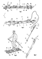
- a roller ski is generally indicated by 1. It comprises a ski 2 having an inner edge 3, an outer edge 4, and that extends from a rear end 5, or briefly tail, to a front end 6, or briefly tip, the latter having a raised configuration as in the common snow ski.
- the ski 2 further has a bottom ground-resting surface 7, or briefly bottom.
- the roller ski 1 comprises a binding 8 which in the present example is shown to be alike a common ski boot binding, employed in on-snow downhills. However, it is understood that the roller ski 1 could mount any type of binding adequate to the foreseen performances and to the footwear. Likewise, the binding 8 could be replaced by a shoe incorporated in the ski body 2.
- the contour of the ski 2 has a marked sidecut, alike that employed in on-snow downhill ski, i.e. the so-called carving ski.
- 'sidecut' it is meant that the edges of the ski 2 have curved profile with opposite convexities, so that the ski waist be narrower with respect to the wider regions corresponding to tip and tail.
- the sidecuts onto the inner edge 3 and the outer edge 4 are substantially symmetrical.
- the roller ski 1 is associated to a respective pole 9 having a handle 10 with a strap 11, a ferrule 12 e, at the latter, a basket 13.
- the roller ski 1 comprises in-line supporting rollers located along the centerline of the ski 2, apt to support the ski 2 while contacting the ground.
- the present embodiment comprises two supporting rollers 20, a front one, located between the binding 8 and the tip 6 and a rear one, located between the binding 8 and the tail 5.
- Said rollers may be of any one dimension, and could therefore be housed in suitable bearings below the bottom 7, or, as in the present embodiment, they could cross the thickness of the ski 2 by virtue of a suitable slot 21.
- said supporting rollers 20 are of the integrated-bearing type, known e.g. for in-line skates, and have a hub 22 fastened to the bottom 7 by fastening plates 23.
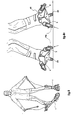
- Said supporting rollers 20 are of the type realizing a substantially punctiform contact on the ground, having a tapered contour and outer diameters that are smaller than the innermost diameters, i.e. than those nearer to the centerline thereof. Hence, said rollers 20 can be tilted preserving a point of contact onto the side surface thereof.
- the material selected for the supporting rollers 20, e.g. a resin, should be adequate in terms of friction and strength.
- the roller ski 1 further comprises a plurality of additional rollers, located at the inner edge 3 and at the outer edge 4 of the ski 2.
- the roller ski 1 has, at each edge of the ski 2, a pair of additional front rollers 24a, at the tip region 6, and a single additional rear roller 24b, at the tail region 5.
- Said additional rollers 24a, 24b are of the type realizing a substantially punctiform contact onto the ground, having a tapered contour and outer diameters smaller than the innermost diameters, i.e. than the diameters nearer to the centerline thereof.
- the material selected for the rollers 24a, 24b e.g. a resin, should be adequate in terms of friction and strength. Both for these latter rollers and for the supporting rollers 20, the rollers commonly employed for in-line rollerblades or rollerskates may be adequate. Rollers having a greater diameter, optionally provided of tires or of other covers, may be selected for employs on uneven and/or soft terrains like carpets, natural or artificial grass, dirt tracks, etc.
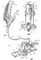
- the additional rollers 24a, 24b are mounted onto the ski 2 by virtue of a bearing 25 that, in present embodiment, is in the shape of an inverted-T and has a fastening plate 26. From the latter there rises a stem 27, comprising at its top a pair of flaps 28 ending in a fork 29, each flap having an additional roller 24a, 24b coupled thereto.
- a bearing 25 that, in present embodiment, is in the shape of an inverted-T and has a fastening plate 26. From the latter there rises a stem 27, comprising at its top a pair of flaps 28 ending in a fork 29, each flap having an additional roller 24a, 24b coupled thereto.
- the additional rollers 24a, 24b located onto the inner edge and onto the outer edge of the ski are destined to alternatively rest on the ground when the ski is tilted on the inside and on the outside (FIGS. 8 and 9A).
- the additional rollers 24a, 24b are located on a curved line C both onto the inner edge 3 and onto the outer edge 4.
- Said curved line C substantially follows the contour of the abovecited sidecut, a shape that facilitates the positioning of the additional rollers.
- said additional rollers could be mounted projecting directly onto the edge of the ski 2, and in this case the additional rollers would be located on a curved line defined directly by the sidecut of the ski 2.
- the abovecited bearing 25 is elastic and hence, when the roller ski 1 is tilted onto the inner or outer edge with the additional rollers 24a, 24b resting on the ground, a greater weight load onto the bearing edge will determine an elastic strain of the bearing 25, facilitating the spring back of the roller ski 1 to a horizontal configuration.
- the elasticity of the bearing 25 is due to the fact that said stem 27 can bend elastically.
- the same effect may be attained with a symmetric leaf spring configuration of the stem 27, with elastic flaps 28, with an elastic hub mounted onto the fork 29, with helical springs mounted between the flap and the fork, or even with actual shock absorbers.
- a symmetric leaf spring configuration of the stem 27 with elastic flaps 28, with an elastic hub mounted onto the fork 29, with helical springs mounted between the flap and the fork, or even with actual shock absorbers.
- the additional rollers 24a, 24b have a camber toward the centerline of the ski 2, so that when the roller ski 1 is tilted sideways the additional rollers 24a, 24b contact the ground substantially vertically.
- the camber is more marked, so that the additional roller 24a, 24b contacting the ground still has a camber toward the centerline of the ski 2. This positioning facilitates the unloading of the weight loaded onto the edge of the ski 2, compensating also the straightening back of the roller determined by the elasticity of the bearing.
- the adjustment of the camber of the additional rollers 24a, 24b, of the elasticity of the bearing 25 or of the camber of the curved line C may be provided.
- said line C is defined by the planes of rotation of the additional rollers 24a, 24b, tangential to said curved line C (figure 3).
- the preferred roller arrangement provides the supporting rollers 20 to lie between the binding 8 and the additional rollers 24a, 24b, whereas the latter will lie between the supporting rollers 20 and the tail 5 and the tip 6, respectively.
- the number of the supporting rollers 20 and/or of the additional rollers will be preselected according to the desired performances, to the skier's weight, and to the length of the ski 2. A marked increase of the latter will be unnecessary, it being optionally reduced as in on-snow carving skis.
- the roller ski 1 has at least one supporting roller 20, in particular the rear one, with evident advantages in terms of stability, provided with a braking system.
- the roller ski 1 could anyhow have a brake, even acting directly on the ground rather than onto the supporting rollers, like e.g. the one taught in US 4,892,332 (Jennings).
- the brake is of the disc type.
- a belt 31 at a first pulley 32 integral thereto.
- a second pulley 33 working as disc houses the belt 31.
- a pincer 34 provided with pads 39 acting onto the disc surface, is located onto the periphery of the second pulley 33 and it is provided with a remotely controlled hydraulic actuator, conventional and not shown in detail.
- a rigid casing 35 fastened to the ski 2 shields the brake 30.
- the remote control may be implemented in several different ways.
- the actuator may comprise an electric power source, e.g. a rechargeable battery, and be radio controlled by a remote control e.g. located in the handle 10, it also power-supplied by an analogous power source.
- the activation is of mechanical type and it comprises a cable 36 housed inside of a sheath 37 extending from the pincer 34 to the handle 10 of the pole 9.
- the brake 30 comprises a lever 38 capable of pulling the cable 36, thereby activating the actuator of the pincer 34 according to a system already tried out in the field of bicycle brakes.
- the abovedescribed disc brake 30 could be replaced by other brake variants, e.g. the pincers could act directly onto the supporting roller, in particular on a specifically provided crown thereof.
- the same brake could be controlled by a skier's shifting the ski boot onto the binding.
- a anti-blocking system well-known in the motor field, i.e. capable of preventing the blocking of the supporting roller with the entailed extension of the braking space.
- the skier During a normal sliding, the skier keeps the roller skis 1 substantially parallel and not tilted sideways.
- the supporting rollers 20 act as a rollerblade system and, being located at the central region of the ski 2, provide a sufficient stability implementable by the skier through an adequate employ of the poles 9.
- the speed due to the gradient of the downhill that is being negotiated, may be adjusted by virtue of the brake 30 (figures 7 and 7A).
- the skier can perform the so-called wedge technique by tilting both skis inwards, thereby ground-contacting the additional rollers 24a, 24b at the inner edge 3 (figures 8 and 8A).
- the additional rollers 24a, 24b lie on a curved line C that facilitates the turning, as it happens e.g. in the abovementioned carving skis.
- the additional rollers 24a, 24b replace the laminae of an on-snow ski concomitantly ensuring the maximum stability of the ski by virtue of the supporting rollers 20 always maintaining a grip.
- a greater weight load determines an elastic strain of the bearing 25 of the additional rollers 24a, 24b, a strain giving the skier a sensation which is very similar to that given by on-snow skiing and turning.
- roller ski fit any off-snow sport or amateur employ. It is understood that the same principles hereto described may fit any ski type: downhill, slalom, cross-country, jump skis, etc. Moreover, the same technical principle may successfully be adopted on monoski and snowboards. Moreover, the abovedescribed roller ski allow turning according to any known technique (christiania, matching skis, Telemark).
- roller ski may be employed for sport training, for amateur practice and for learning.
- roller ski a person skilled in the art in order to meet further and contingent needs may effect several further modifications and variants, all however comprised within the protective scope of the present invention, as defined by the appended claims.
Claims (14)
- Ski à roulettes (1), comportant :- des roulettes de support alignées (20) situées le long de l'axe central du ski (2), aptes à supporter le ski (2) tout en étant en contact avec le sol, et- une pluralité de roulettes supplémentaires (24a, 24b), situées sur le bord intérieur (3) et sur le bord extérieur (4) du ski (2), lesdites roulettes supplémentaires (24a, 24b) étant surélevées par rapport au sol,dans lequel les roulettes supplémentaires (24a, 24b) sont situées sur une ligne incurvée (C) entre la fixation (B) et la zone de pointe (6) et entre la fixation (8) et la zone de talon (5), et dans lequel les roulettes supplémentaires (24a, 24b) sont situées sur le bord intérieur (3) et sur le bord extérieur (4) du ski (2) dans la zone de pointe (6) et la zone de talon (5), étant aptes à reposer alternativement sur le sol lorsque le ski (2) est basculé sur l'intérieur et sur l'extérieur, respectivement
caractérisé en ce que les roulettes supplémentaires (24a, 24b) sont montées sur le ski (2) par l'intermédiaire d'un support élastique (25). - Ski à roulettes (1) selon la revendication 1, dans lequel le contour du ski (2) a une découpe latérale sur le bord intérieur (3) et le bord extérieur (4), ladite ligne incurvée (C) suivant sensiblement le contour de ladite découpe latérale.
- Ski à roulettes (1) selon la revendication 2, dans lequel les roulettes supplémentaires (24a, 24b) sont montées faisant saillie directement sur le bord du ski (2), ladite ligne incurvée (C) étant ainsi définie directement par la découpe latérale du ski (2).
- Ski à roulettes (1) selon la revendication 1, dans lequel les roulettes supplémentaires (24a, 24b) ont une cambrure vers l'axe central du ski (2), de sorte que lorsque le ski à roulettes (1) est basculé vers le côté, les roulettes supplémentaires (24a, 24b) viennent en contact avec le sol de manière sensiblement verticale, ou avec une cambrure vers l'axe central du ski (2).
- Ski à roulettes (1) selon la revendication 1, dans lequel l'espacement des roulettes (20, 24a, 24b) fait que les roulettes de support (20) se trouvent entre la fixation (8) et les roulettes supplémentaires (24a, 24b), alors que ces dernières vont se trouver entre les roulettes de support (20) et le talon (5) et la pointe (6), respectivement.
- Ski à roulettes (1) selon la revendication 1, dans lequel au moins un rouleau de support (20) est muni d'un système de freinage.
- Ski à roulettes (1) selon la revendication 6, dans lequel le système de freinage agit sur une roulette de support arrière (20).
- Ski à roulettes (1) selon la revendication 6 ou 7, dans lequel le système de freinage comporte un frein de type à disque (30).
- Ski à roulettes (1) selon la revendication 8, dans lequel sur une roulette de support (20), une courroie (31) est fixée au niveau d'une première poulie (32) en un seul bloc avec la roue de support (20), et d'une deuxième poulie (33), agissant comme un disque, reçoit la courroie (31), et elle est munie d'un dispositif de pincement (34) agissant sur la surface du disque, positionné à la périphérie de la seconde poulie (33).
- Ski à roulettes (1) selon la revendication 6 ou 7, dans lequel le système de freinage comporte un actionneur commandé à distance.
- Ski à roulettes (1) selon la revendication 10, dans lequel l'actionneur comporte une source de puissance électrique, et est radiocommandé par une commande à distance alimentée en puissance par une source de puissance analogue.
- Ski à roulettes (1) selon la revendication 10, dans lequel l'actionneur a un actionnement de type mécanique comportant un câble (36), logé à l'intérieur d'une gaine (37), et un levier (38) capable de tirer le câble (36), en actionnant ainsi l'actionneur.
- Ski à roulettes (1) selon la revendication 11 ou 12, dans lequel la commande à distance ou le levier (38) sont associés à une poignée (10) d'un bâton de ski (9).
- Ski à roulettes (1) selon la revendication 13, dans lequel le système de freinage comporte un système antiblocage.
Applications Claiming Priority (1)
| Application Number | Priority Date | Filing Date | Title |
|---|---|---|---|
| PCT/IT2002/000682 WO2004037358A1 (fr) | 2002-10-28 | 2002-10-28 | Ski a roulettes |
Publications (2)
| Publication Number | Publication Date |
|---|---|
| EP1556146A1 EP1556146A1 (fr) | 2005-07-27 |
| EP1556146B1 true EP1556146B1 (fr) | 2006-05-24 |
Family
ID=32170668
Family Applications (1)
| Application Number | Title | Priority Date | Filing Date |
|---|---|---|---|
| EP02788537A Expired - Lifetime EP1556146B1 (fr) | 2002-10-28 | 2002-10-28 | Ski a roulettes |
Country Status (6)
| Country | Link |
|---|---|
| EP (1) | EP1556146B1 (fr) |
| AT (1) | ATE327012T1 (fr) |
| AU (1) | AU2002353512A1 (fr) |
| DE (1) | DE60211757T2 (fr) |
| ES (1) | ES2265059T3 (fr) |
| WO (1) | WO2004037358A1 (fr) |
Families Citing this family (6)
| Publication number | Priority date | Publication date | Assignee | Title |
|---|---|---|---|---|
| DE102006018505A1 (de) * | 2006-04-21 | 2007-10-25 | Reinhard Wittner | Gelände-Inline-Skates |
| DE102007007176A1 (de) * | 2007-02-09 | 2008-08-14 | Duong, Gilbert, Dr. | Gleitrollen für Skier |
| IT1394607B1 (it) * | 2009-06-08 | 2012-07-05 | Bolditalia S R L | Perfezionamento negli sci o tavola su ruote. |
| US10071303B2 (en) | 2015-08-26 | 2018-09-11 | Malibu Innovations, LLC | Mobilized cooler device with fork hanger assembly |
| US10807659B2 (en) | 2016-05-27 | 2020-10-20 | Joseph L. Pikulski | Motorized platforms |
| RU2725642C1 (ru) * | 2019-05-13 | 2020-07-03 | Николай Васильевич Вагин | Транспорт |
Family Cites Families (9)
| Publication number | Priority date | Publication date | Assignee | Title |
|---|---|---|---|---|
| DE3617245C1 (de) | 1986-05-22 | 1987-06-04 | Engelbert Schmid | Bremseinrichtung fuer einen Rollski |
| US4887824A (en) * | 1987-08-24 | 1989-12-19 | Jeffrey Zatlin | Skatecraft |
| US4886298A (en) | 1987-11-30 | 1989-12-12 | Shols Christopher B | Roller ski |
| US4892332A (en) | 1988-11-04 | 1990-01-09 | Ryan Jennings | Braking system for roller skis |
| US5195781A (en) | 1989-03-28 | 1993-03-23 | Kazuo Osawa | Grass ski roller boards |
| JP2993652B2 (ja) * | 1993-02-13 | 1999-12-20 | ユニテック 株式会社 | 電動遊戯具 |
| US6237960B1 (en) | 1994-03-01 | 2001-05-29 | Siegfried Dornhofer | Roller-type skiing device for negotiating a slope |
| US5855385A (en) * | 1996-09-23 | 1999-01-05 | Hambsch; Stephen G. | Wheeled board apparatus having platform with concave sidecuts |
| JP4267747B2 (ja) | 1999-03-03 | 2009-05-27 | 和雄 大澤 | ローラースキー |
-
2002
- 2002-10-28 AT AT02788537T patent/ATE327012T1/de active
- 2002-10-28 ES ES02788537T patent/ES2265059T3/es not_active Expired - Lifetime
- 2002-10-28 EP EP02788537A patent/EP1556146B1/fr not_active Expired - Lifetime
- 2002-10-28 WO PCT/IT2002/000682 patent/WO2004037358A1/fr not_active Application Discontinuation
- 2002-10-28 DE DE60211757T patent/DE60211757T2/de not_active Expired - Lifetime
- 2002-10-28 AU AU2002353512A patent/AU2002353512A1/en not_active Abandoned
Also Published As
| Publication number | Publication date |
|---|---|
| ATE327012T1 (de) | 2006-06-15 |
| ES2265059T3 (es) | 2007-02-01 |
| WO2004037358A1 (fr) | 2004-05-06 |
| EP1556146A1 (fr) | 2005-07-27 |
| AU2002353512A1 (en) | 2004-05-13 |
| DE60211757D1 (de) | 2006-06-29 |
| DE60211757T2 (de) | 2007-05-16 |
Similar Documents
| Publication | Publication Date | Title |
|---|---|---|
| US5401037A (en) | Composite wheels for in-line roller skates | |
| US8251377B2 (en) | Roller skate and wheel trucks therefor | |
| US5286043A (en) | Roller skate | |
| US4886298A (en) | Roller ski | |
| US3522951A (en) | Method for modifying conventional snow skiis to permit downhill skiing on smooth grassy slopes during non-winter periods | |
| US20120126523A1 (en) | Laterally sliding roller ski | |
| US20100289230A1 (en) | Single foot skate | |
| US20030094788A1 (en) | Magnetic snow equipment attachment system | |
| US5408763A (en) | Skate with aligned wheels having an adjustable quarter | |
| US20020158429A1 (en) | Three-wheeled roller skate and method therefor | |
| EP1702657A1 (fr) | Ski avec caractéristiques d'accroche des carres améliorées | |
| CA2686334A1 (fr) | Planche a neige | |
| US5901981A (en) | Roller-ski and brake apparatus | |
| WO1997048459A9 (fr) | Skis a roulettes | |
| US5806860A (en) | Frame for skates with aligned wheels | |
| EP1556146B1 (fr) | Ski a roulettes | |
| US6113113A (en) | Sliding apparatus having adjustable flexion and torsion characteristics | |
| CA2055565C (fr) | Ski a roulettes | |
| US5527049A (en) | Digger for in-line roller skate | |
| US4363492A (en) | Roller ski for training long distance skiing | |
| US6244615B1 (en) | Individual snowboard for each foot | |
| EP0938355B1 (fr) | Systeme de suspension independant pour patins en ligne | |
| WO2000023157A1 (fr) | Dispositif de patin a roulettes | |
| FR2745988A1 (fr) | Chaussures de sport guidees par des jambieres et dispositif de freinage adapte | |
| GB2325142A (en) | Activity shoe and attachable footwear |
Legal Events
| Date | Code | Title | Description |
|---|---|---|---|
| PUAI | Public reference made under article 153(3) epc to a published international application that has entered the european phase |
Free format text: ORIGINAL CODE: 0009012 |
|
| 17P | Request for examination filed |
Effective date: 20050429 |
|
| AK | Designated contracting states |
Kind code of ref document: A1 Designated state(s): AT BE BG CH CY CZ DE DK EE ES FI FR GB GR IE IT LI LU MC NL PT SE SK TR |
|
| AX | Request for extension of the european patent |
Extension state: AL LT LV MK RO SI |
|
| GRAP | Despatch of communication of intention to grant a patent |
Free format text: ORIGINAL CODE: EPIDOSNIGR1 |
|
| DAX | Request for extension of the european patent (deleted) | ||
| GRAS | Grant fee paid |
Free format text: ORIGINAL CODE: EPIDOSNIGR3 |
|
| GRAA | (expected) grant |
Free format text: ORIGINAL CODE: 0009210 |
|
| AK | Designated contracting states |
Kind code of ref document: B1 Designated state(s): AT BE BG CH CY CZ DE DK EE ES FI FR GB GR IE IT LI LU MC NL PT SE SK TR |
|
| PG25 | Lapsed in a contracting state [announced via postgrant information from national office to epo] |
Ref country code: IT Free format text: LAPSE BECAUSE OF FAILURE TO SUBMIT A TRANSLATION OF THE DESCRIPTION OR TO PAY THE FEE WITHIN THE PRESCRIBED TIME-LIMIT;WARNING: LAPSES OF ITALIAN PATENTS WITH EFFECTIVE DATE BEFORE 2007 MAY HAVE OCCURRED AT ANY TIME BEFORE 2007. THE CORRECT EFFECTIVE DATE MAY BE DIFFERENT FROM THE ONE RECORDED. Effective date: 20060524 Ref country code: FI Free format text: LAPSE BECAUSE OF FAILURE TO SUBMIT A TRANSLATION OF THE DESCRIPTION OR TO PAY THE FEE WITHIN THE PRESCRIBED TIME-LIMIT Effective date: 20060524 Ref country code: NL Free format text: LAPSE BECAUSE OF FAILURE TO SUBMIT A TRANSLATION OF THE DESCRIPTION OR TO PAY THE FEE WITHIN THE PRESCRIBED TIME-LIMIT Effective date: 20060524 Ref country code: CZ Free format text: LAPSE BECAUSE OF FAILURE TO SUBMIT A TRANSLATION OF THE DESCRIPTION OR TO PAY THE FEE WITHIN THE PRESCRIBED TIME-LIMIT Effective date: 20060524 Ref country code: SK Free format text: LAPSE BECAUSE OF FAILURE TO SUBMIT A TRANSLATION OF THE DESCRIPTION OR TO PAY THE FEE WITHIN THE PRESCRIBED TIME-LIMIT Effective date: 20060524 Ref country code: BE Free format text: LAPSE BECAUSE OF FAILURE TO SUBMIT A TRANSLATION OF THE DESCRIPTION OR TO PAY THE FEE WITHIN THE PRESCRIBED TIME-LIMIT Effective date: 20060524 |
|
| REG | Reference to a national code |
Ref country code: GB Ref legal event code: FG4D |
|
| REG | Reference to a national code |
Ref country code: CH Ref legal event code: EP |
|
| REG | Reference to a national code |
Ref country code: IE Ref legal event code: FG4D |
|
| REF | Corresponds to: |
Ref document number: 60211757 Country of ref document: DE Date of ref document: 20060629 Kind code of ref document: P |
|
| PG25 | Lapsed in a contracting state [announced via postgrant information from national office to epo] |
Ref country code: SE Free format text: LAPSE BECAUSE OF FAILURE TO SUBMIT A TRANSLATION OF THE DESCRIPTION OR TO PAY THE FEE WITHIN THE PRESCRIBED TIME-LIMIT Effective date: 20060824 Ref country code: DK Free format text: LAPSE BECAUSE OF FAILURE TO SUBMIT A TRANSLATION OF THE DESCRIPTION OR TO PAY THE FEE WITHIN THE PRESCRIBED TIME-LIMIT Effective date: 20060824 |
|
| REG | Reference to a national code |
Ref country code: CH Ref legal event code: NV Representative=s name: PATENTANWAELTE SCHAAD, BALASS, MENZL & PARTNER AG |
|
| PG25 | Lapsed in a contracting state [announced via postgrant information from national office to epo] |
Ref country code: PT Free format text: LAPSE BECAUSE OF FAILURE TO SUBMIT A TRANSLATION OF THE DESCRIPTION OR TO PAY THE FEE WITHIN THE PRESCRIBED TIME-LIMIT Effective date: 20061024 |
|
| PG25 | Lapsed in a contracting state [announced via postgrant information from national office to epo] |
Ref country code: MC Free format text: LAPSE BECAUSE OF NON-PAYMENT OF DUE FEES Effective date: 20061031 Ref country code: IE Free format text: LAPSE BECAUSE OF NON-PAYMENT OF DUE FEES Effective date: 20061031 |
|
| NLV1 | Nl: lapsed or annulled due to failure to fulfill the requirements of art. 29p and 29m of the patents act | ||
| ET | Fr: translation filed | ||
| REG | Reference to a national code |
Ref country code: ES Ref legal event code: FG2A Ref document number: 2265059 Country of ref document: ES Kind code of ref document: T3 |
|
| PLBE | No opposition filed within time limit |
Free format text: ORIGINAL CODE: 0009261 |
|
| STAA | Information on the status of an ep patent application or granted ep patent |
Free format text: STATUS: NO OPPOSITION FILED WITHIN TIME LIMIT |
|
| 26N | No opposition filed |
Effective date: 20070227 |
|
| PG25 | Lapsed in a contracting state [announced via postgrant information from national office to epo] |
Ref country code: GR Free format text: LAPSE BECAUSE OF FAILURE TO SUBMIT A TRANSLATION OF THE DESCRIPTION OR TO PAY THE FEE WITHIN THE PRESCRIBED TIME-LIMIT Effective date: 20060825 |
|
| PG25 | Lapsed in a contracting state [announced via postgrant information from national office to epo] |
Ref country code: BG Free format text: LAPSE BECAUSE OF FAILURE TO SUBMIT A TRANSLATION OF THE DESCRIPTION OR TO PAY THE FEE WITHIN THE PRESCRIBED TIME-LIMIT Effective date: 20060824 Ref country code: EE Free format text: LAPSE BECAUSE OF FAILURE TO SUBMIT A TRANSLATION OF THE DESCRIPTION OR TO PAY THE FEE WITHIN THE PRESCRIBED TIME-LIMIT Effective date: 20060524 |
|
| PG25 | Lapsed in a contracting state [announced via postgrant information from national office to epo] |
Ref country code: TR Free format text: LAPSE BECAUSE OF FAILURE TO SUBMIT A TRANSLATION OF THE DESCRIPTION OR TO PAY THE FEE WITHIN THE PRESCRIBED TIME-LIMIT Effective date: 20060524 Ref country code: LU Free format text: LAPSE BECAUSE OF NON-PAYMENT OF DUE FEES Effective date: 20061028 |
|
| PG25 | Lapsed in a contracting state [announced via postgrant information from national office to epo] |
Ref country code: CY Free format text: LAPSE BECAUSE OF FAILURE TO SUBMIT A TRANSLATION OF THE DESCRIPTION OR TO PAY THE FEE WITHIN THE PRESCRIBED TIME-LIMIT Effective date: 20060524 |
|
| PG25 | Lapsed in a contracting state [announced via postgrant information from national office to epo] |
Ref country code: IT Free format text: LAPSE BECAUSE OF NON-PAYMENT OF DUE FEES Effective date: 20081028 |
|
| PGFP | Annual fee paid to national office [announced via postgrant information from national office to epo] |
Ref country code: GB Payment date: 20101029 Year of fee payment: 9 |
|
| PGRI | Patent reinstated in contracting state [announced from national office to epo] |
Ref country code: IT Effective date: 20110616 |
|
| PGFP | Annual fee paid to national office [announced via postgrant information from national office to epo] |
Ref country code: ES Payment date: 20111125 Year of fee payment: 10 |
|
| GBPC | Gb: european patent ceased through non-payment of renewal fee |
Effective date: 20121028 |
|
| PGFP | Annual fee paid to national office [announced via postgrant information from national office to epo] |
Ref country code: AT Payment date: 20130411 Year of fee payment: 11 |
|
| PG25 | Lapsed in a contracting state [announced via postgrant information from national office to epo] |
Ref country code: GB Free format text: LAPSE BECAUSE OF NON-PAYMENT OF DUE FEES Effective date: 20121028 |
|
| PGFP | Annual fee paid to national office [announced via postgrant information from national office to epo] |
Ref country code: DE Payment date: 20130422 Year of fee payment: 11 Ref country code: CH Payment date: 20130411 Year of fee payment: 11 |
|
| PGFP | Annual fee paid to national office [announced via postgrant information from national office to epo] |
Ref country code: FR Payment date: 20130502 Year of fee payment: 11 |
|
| REG | Reference to a national code |
Ref country code: CH Ref legal event code: PL |
|
| REG | Reference to a national code |
Ref country code: AT Ref legal event code: MM01 Ref document number: 327012 Country of ref document: AT Kind code of ref document: T Effective date: 20131028 |
|
| REG | Reference to a national code |
Ref country code: DE Ref legal event code: R119 Ref document number: 60211757 Country of ref document: DE Effective date: 20140501 |
|
| PG25 | Lapsed in a contracting state [announced via postgrant information from national office to epo] |
Ref country code: CH Free format text: LAPSE BECAUSE OF NON-PAYMENT OF DUE FEES Effective date: 20131031 Ref country code: LI Free format text: LAPSE BECAUSE OF NON-PAYMENT OF DUE FEES Effective date: 20131031 |
|
| REG | Reference to a national code |
Ref country code: FR Ref legal event code: ST Effective date: 20140630 |
|
| PG25 | Lapsed in a contracting state [announced via postgrant information from national office to epo] |
Ref country code: AT Free format text: LAPSE BECAUSE OF NON-PAYMENT OF DUE FEES Effective date: 20131028 Ref country code: DE Free format text: LAPSE BECAUSE OF NON-PAYMENT OF DUE FEES Effective date: 20140501 Ref country code: FR Free format text: LAPSE BECAUSE OF NON-PAYMENT OF DUE FEES Effective date: 20131031 |
|
| PGFP | Annual fee paid to national office [announced via postgrant information from national office to epo] |
Ref country code: IT Payment date: 20140430 Year of fee payment: 12 |
|
| REG | Reference to a national code |
Ref country code: ES Ref legal event code: FD2A Effective date: 20141107 |
|
| PG25 | Lapsed in a contracting state [announced via postgrant information from national office to epo] |
Ref country code: ES Free format text: LAPSE BECAUSE OF NON-PAYMENT OF DUE FEES Effective date: 20131029 |
|
| PG25 | Lapsed in a contracting state [announced via postgrant information from national office to epo] |
Ref country code: IT Free format text: LAPSE BECAUSE OF NON-PAYMENT OF DUE FEES Effective date: 20141028 |