EP1555728B1 - Electrical Connector - Google Patents
Electrical Connector Download PDFInfo
- Publication number
- EP1555728B1 EP1555728B1 EP04000887A EP04000887A EP1555728B1 EP 1555728 B1 EP1555728 B1 EP 1555728B1 EP 04000887 A EP04000887 A EP 04000887A EP 04000887 A EP04000887 A EP 04000887A EP 1555728 B1 EP1555728 B1 EP 1555728B1
- Authority
- EP
- European Patent Office
- Prior art keywords
- connector
- seal
- contact
- accordance
- receiving region
- Prior art date
- Legal status (The legal status is an assumption and is not a legal conclusion. Google has not performed a legal analysis and makes no representation as to the accuracy of the status listed.)
- Expired - Lifetime
Links
- 230000037431 insertion Effects 0.000 claims description 15
- 238000003780 insertion Methods 0.000 claims description 15
- 239000000463 material Substances 0.000 claims description 3
- 239000003566 sealing material Substances 0.000 abstract description 9
- 230000006378 damage Effects 0.000 description 6
- XLYOFNOQVPJJNP-UHFFFAOYSA-N water Substances O XLYOFNOQVPJJNP-UHFFFAOYSA-N 0.000 description 1
Images


Classifications
-
- H—ELECTRICITY
- H01—ELECTRIC ELEMENTS
- H01R—ELECTRICALLY-CONDUCTIVE CONNECTIONS; STRUCTURAL ASSOCIATIONS OF A PLURALITY OF MUTUALLY-INSULATED ELECTRICAL CONNECTING ELEMENTS; COUPLING DEVICES; CURRENT COLLECTORS
- H01R13/00—Details of coupling devices of the kinds covered by groups H01R12/70 or H01R24/00 - H01R33/00
- H01R13/46—Bases; Cases
- H01R13/52—Dustproof, splashproof, drip-proof, waterproof, or flameproof cases
- H01R13/5205—Sealing means between cable and housing, e.g. grommet
Definitions
- the invention relates to an electrical connector specified in the preamble of claim 1.
- Such a connector is described in EP-A-1 204 174.
- the seal arranged in the entrance area of the chamber is made in one piece.
- the invention has for its object to provide an improved electrical connector of the type mentioned, in which the aforementioned problems are eliminated in the simplest and most reliable manner.
- the cross section of a respective receiving area increases toward the seal.
- the rear receiving area it can therefore have a larger opening cross-section at its end facing the seal than at its end facing the chamber.
- the front receiving area may have a larger opening cross section at its end facing the seal than at its other end, for example facing an insertion opening.
- the rear receiving area may be provided in the contact insertion direction, in particular between the seal and the chamber or between the seal and the input-side chamber edge.
- the rear receiving area may in particular comprise a joint or the like.
- the rear receiving area is dimensioned so that at least substantially no sealing material enters the chamber when equipping the connector.
- the front receiving area may in particular be provided on the inside of an end wall of the connector provided with at least one contact opening.
- the end wall may be formed for example by a film hinge flap or the like.
- the rear receiving area is bounded by two opposing walls diverging towards the seal. Possibly.
- the front receiving area may also be delimited by two such walls which are opposite each other and which tend to seal.
- the seal in the region of a respective electrical contact in the contact plug-in direction is divided into at least two plug-in areas spaced from one another in the contact plug-in direction. If the seal as a whole is subdivided into at least two layers or layers, then the plug-in regions which have a distance from one another in the contact plug-in direction can be distributed to these layers or layers.
- a respective plug-in area for the associated electrical contact is provided with an opening whose maximum diameter is preferably smaller than the maximum transverse dimension of the respective contact and in particular smaller than the outer diameter of the respective line at which provided the contact is.
- the invention is applicable to all sealed connectors whose seal is formed by a block seal or subdivided into multiple layers.
- an electrical connector 10 which may be, for example, a connector.
- the electrical connector 10 comprises a plurality of chambers 12 for receiving electrical contacts 14 and a seal 16 arranged in the entry region of the chambers 12. When the electrical connector 10 is fitted, the electrical contacts 14 are inserted or pierced through this seal 16.
- a receiving region 20 which is extended transversely to the contact plug-in direction KS can also be provided directly in front of the seal 16.
- Such a front receiving area 20 serves to receive sealing material displaced when a respective contact 14 is withdrawn.
- a respective rear receiving portion 18 is seen in the contact plug KS viewed between the seal 16 and the associated chamber 12 and between the seal 16 and the input-side edge 22 of the chamber 12.
- the rear receiving area 18 may, for example, comprise a joint. Accordingly, the front receiving area 20 may be formed, for example, by a joint or the like.
- the rear receiving area 18 is now preferably dimensioned so that at least substantially no sealing material enters the chamber 12 when the electrical connector 10 is being fitted.
- the front receiving area 20 is provided on the inside of an end wall 26 of the electrical connector 10 provided with at least one contact opening 24.
- the end wall 26 may be formed, for example, by a film hinge flap 28 or the like.
- the rear receiving area 18 in the present case is bounded by two opposing walls 18 ', 18 "which are diverging towards the seal 16.
- the front receiving area 20 can also be delimited by two opposing walls 20 ', 20 "that are diverging towards the seal 16 (cf., in particular, FIGS. 1 and 4).
- the seal 16 is viewed in Kunststoffsteckcardi KS divided into several layers or layers. In the present exemplary embodiment, the seal 16 is subdivided into two successive layers 16 1 , 16 2 in the contact plug-in direction KS (cf., in particular, FIGS. 1, 3 and 4 to 7).
- the seal 16 can be subdivided into at least two plug-in regions 30 having a distance a from one another in the contact plug-in direction KS (cf., in particular, FIG. In the present case, a subdivision into two such plug-in areas 30 is provided.
- the seal 16 is subdivided, for example, into two layers or layers 16 1 , 16 2 , and the plug-in regions 30 having a distance a from one another in contact plug-in direction KS are distributed to these layers or layers 16 1 , 16 2 .
- a respective plug-in area 30 can be provided, for example, with an opening 32 for the associated electrical contact 14 (cf., in particular, FIGS. 1 and 3 to 5).
- the maximum diameter of such an opening 32 is preferably smaller than the maximum transverse dimension of the relevant electrical contact 14 and in particular smaller than the outer diameter of the relevant line on which the contact 14 is provided.
- FIG. 1 shows the electrical connector 10 in a schematic cross-sectional view, in which the electrical contacts 14 (cf., for example, FIG. 2) have been omitted for the sake of clarity.
- a corresponding electrical contact which can be inserted in the connector 10 is shown for example in FIG. 2.
- Fig. 3 shows the electrical connector 10 in a schematic longitudinal sectional view. Also in this case, the electrical contacts 14 (cf., in particular, again FIG. 2) have been omitted for the sake of clarity.
- the double arrow in the representation according to FIG. 2 indicates that the sealing material displaced during the insertion or removal of the electrical contact 14 is received in the rear receiving region 18 or the front receiving region 20.
- FIG 4 shows the electrical connector 10 in a schematic perspective partial view, whereby an electrical contact 14 to be pierced through the seal 16 is also shown.
- the electrical contact 14 is brought through the contact opening 24 of the film hinge flap 28 only up to the seal 16, but not yet inserted therethrough.
- FIG 5 shows the electrical connector 10 in a phase in which the electrical contact 14 has already been inserted so far that it passes through the first layer 16 1 of the seal 16.
- Fig. 6 the electrical connector 10 is shown in a phase in which the electrical contact 14 is already used so far that it passes through both layers 16 1 , 16 2 of the seal 16.
- Fig. 7 shows the electrical connector 10 in a phase in which the electrical contact 14 has reached its end position in which it protrudes with one end into the relevant chamber 12 and is surrounded by the seal 16 in the region of its other end.
- FIG 8 shows a schematic plan view of a part of the electrical connector 10 with the film hinge flap 28 open.
- the electrical contacts 14 and the seal 16 have been omitted for the sake of clarity.
- FIG. 9 shows a schematic inside view of a part of the film hinge flap 28.
- the two opposing walls 20 ', 20 "diverging towards the seal 16 can be seen, by which the front receiving area 20 is bounded laterally.
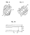
- Fig. 10 shows in a schematic longitudinal sectional view again a chamber 12 of the electrical connector 10 with a chamber 12 adjacent to this rear receiving area 18. This results in the present case per chamber each an increase in space, for example, about 20% for the onset of the relevant electrical contact displaced sealing material.
- the receiving areas 18, 20 have, for example, a trapezoidal cross section (cf., for example, FIGS. 1 and 10).
- the respective cross section of these receiving areas 18, 20 may, however, in principle also have any other shape.
- these areas may also be rectangular, oval, round, elliptical, etc.
Landscapes
- Connector Housings Or Holding Contact Members (AREA)
- Details Of Connecting Devices For Male And Female Coupling (AREA)
Abstract
Description
Die Erfindung betrifft einen elektrischen Verbinder der im Oberbegriff des Anspruchs 1 angegebenen Art. Ein derartiger Verbinder ist in der EP-A-1 204 174 beschrieben.The invention relates to an electrical connector specified in the preamble of claim 1. Such a connector is described in EP-A-1 204 174.
Bei herkömmlichen elektrischen Verbindern wird das beim Bestücken des Verbinders, d.h. beim Einsetzen der elektrischen Kontakte in die zugeordneten Kammern zu verdrängende Dichtungsmaterial bis in die jeweilige Kammer durchgeführt, was relativ hohe Steckkräfte mit sich bringt und zu einer Beschädigung oder gar Zerstörung der Dichtung führen kann, was einem Ausfall des betreffenden Verbinders gleichkommt. Die hohen Steckkräfte bringen u.a. auch die Gefahr mit sich, dass die mit den Kontakten versehenen Leitungen leicht abknicken und sich die Kontakte bei der Herstellung der jeweiligen gewünschten elektrischen Verbindung nicht mehr richtig stecken lassen. Indem die Dichtung beim Einstecken eines jeweiligen Kontaktes in die zugeordnete Kammer im Bereich der eingangsseitigen Kante sowie der Wand der Kammer gequetscht wird und entsprechend zerstört werden kann, kann also Wasser in die jeweilige Kammer eindringen, wodurch die Funktionsfähigkeit des Verbinders zumindest erheblich beeinträchtigt wird. Auch beim Herausziehen der elektrischen Kontakte kann es insbesondere wieder aufgrund eines Einquetschens des zu verdrängenden Dichtungsmaterials zu einer Beschädigung oder Zerstörung der Dichtung kommen.In conventional electrical connectors, this is done when loading the connector, i. when inserting the electrical contacts into the associated chambers to be displaced sealing material carried out into the respective chamber, which brings relatively high insertion forces and can lead to damage or even destruction of the seal, which is equivalent to a failure of the relevant connector. The high insertion forces bring u.a. There is also the risk that the lines provided with the contacts will bend slightly and the contacts can no longer be properly inserted in the production of the respective desired electrical connection. By squeezing the seal upon insertion of a respective contact in the associated chamber in the region of the input side edge and the wall of the chamber and can be destroyed accordingly, so water can penetrate into the respective chamber, whereby the operability of the connector is at least significantly affected. Also, when pulling out the electrical contacts, it may in particular come due to a crushing of the seal material to be displaced to damage or destruction of the seal.
Bei dem aus der EP-A-1 204 174 bekannten elektrischen Verbinder ist die im Eingangsbereich der Kammer angeordnete Dichtung einstückig ausgeführt.In the electrical connector known from EP-A-1 204 174, the seal arranged in the entrance area of the chamber is made in one piece.
Der Erfindung liegt die Aufgabe zugrunde, einen verbesserten elektrischen Verbinder der eingangs genannten Art zu schaffen, bei dem die zuvor genannten Probleme auf möglichst einfache und zuverlässige Weise beseitigt sind.The invention has for its object to provide an improved electrical connector of the type mentioned, in which the aforementioned problems are eliminated in the simplest and most reliable manner.
Diese Aufgabe wird nach der Erfindung dadurch gelöst, dass die Dichtung, in Kontaktsteckrichtung betrachtet in zumindest zwei Schichten unterteilt ist.This object is achieved according to the invention in that the seal, viewed in Kontaktsteckrichtung is divided into at least two layers.
Damit besteht z.B. die Möglichkeit, mehrere Steckbereiche auf mehrere Lagen bzw. Schichten zu verteilen.There is e.g. the possibility of distributing several plug-in areas over several layers or layers.
Dabei wird durch den hinteren Aufnahmebereich das beim Einsetzen eines jeweiligen elektrischen Kontaktes verdrängte Dichtungsmaterial aufgenommen, so dass dieses nicht mehr in die betreffende Kammer gelangen kann. Eine Beschädigung der Dichtung ist somit ausgeschlossen. Zudem werden die Steckkräfte in dem gewünschten Bereich, d.h. relativ klein gehalten. Mit einem jeweiligen vorderen Aufnahmebereich ist auch beim Herausziehen der elektrischen Kontakte sichergestellt, dass es zu keiner Beschädigung der Dichtung kommt.In this case, the displaced upon insertion of a respective electrical contact sealing material is received by the rear receiving area, so that it can no longer get into the relevant chamber. Damage to the seal is thus excluded. In addition, the insertion forces in the desired area, i. kept relatively small. With a respective front receiving area is ensured even when pulling out the electrical contacts that there is no damage to the seal.
Zweckmäßigerweise nimmt der Querschnitt eines jeweiligen Aufnahmebereichs zur Dichtung hin zu. Was den hinteren Aufnahmebereich betrifft, so kann dieser also an seinem der Dichtung zugewandten Ende einen größeren Öffnungsquerschnitt besitzen als an seinem der Kammer zugewandeten Ende. Was den vorderen Aufnahmebereich betrifft, so kann dieser an seinem der Dichtung zugewandten Ende einen größeren Öffnungsquerschnitt besitzen als an seinem anderen, z.B. einer Einführöffnung zugewandten Ende.Conveniently, the cross section of a respective receiving area increases toward the seal. As far as the rear receiving area is concerned, it can therefore have a larger opening cross-section at its end facing the seal than at its end facing the chamber. As far as the front receiving area is concerned, it may have a larger opening cross section at its end facing the seal than at its other end, for example facing an insertion opening.
Der hintere Aufnahmebereich kann in Kontaktsteckrichtung betrachtet insbesondere zwischen der Dichtung und der Kammer bzw. zwischen der Dichtung und der eingangsseitigen Kammerkante vorgesehen sein.The rear receiving area may be provided in the contact insertion direction, in particular between the seal and the chamber or between the seal and the input-side chamber edge.
Der hintere Aufnahmebereich kann insbesondere eine Fuge oder dergleichen umfassen. Dasselbe gilt auch für den vorderen Aufnahmebereich. Auch dieser kann also beispielsweise wieder durch eine Fuge oder dergleichen gebildet sein.The rear receiving area may in particular comprise a joint or the like. The same applies to the front recording area. This, too, can thus be formed, for example, again by a joint or the like.
Bevorzugt ist der hintere Aufnahmebereich so dimensioniert, dass beim Bestücken des Verbinders zumindest im Wesentlichen kein Dichtungsmaterial in die Kammer gelangt.Preferably, the rear receiving area is dimensioned so that at least substantially no sealing material enters the chamber when equipping the connector.
Der vordere Aufnahmebereich kann insbesondere auf der Innenseite einer mit wenigstens einer Kontaktöffnung versehenen Stirnwand des Verbinders vorgesehen sein. Die Stirnwand kann beispielsweise durch eine Filmscharnierklappe oder dergleichen gebildet sein.The front receiving area may in particular be provided on the inside of an end wall of the connector provided with at least one contact opening. The end wall may be formed for example by a film hinge flap or the like.
Bei einer bevorzugten praktischen Ausführungsform des erfindungsgemäßen Verbinders ist der hintere Aufnahmebereich durch zwei einander gegenüberliegende, zur Dichtung hin divergierende Wände begrenzt. Ggf. kann auch der vordere Aufnahmebereich durch zwei solche einander gegenüberliegende, zur Dichtung hin divergierende Wände begrenzt sein.In a preferred practical embodiment of the connector according to the invention, the rear receiving area is bounded by two opposing walls diverging towards the seal. Possibly. The front receiving area may also be delimited by two such walls which are opposite each other and which tend to seal.
Von Vorteil ist insbesondere auch, wenn die Dichtung im Bereich eines jeweiligen elektrischen Kontaktes in Kontaktsteckrichtung betrachtet in zumindest zwei in Kontaktsteckrichtung einen Abstand voneinander aufweisende Steckbereiche unterteilt ist. Ist die Dichtung insgesamt in zumindest zwei Lagen bzw. Schichten unterteilt, so können die in Kontaktsteckrichtung einen Abstand voneinander aufweisenden Steckbereiche auf diese Lagen bzw. Schichten verteilt sein.It is particularly advantageous if the seal in the region of a respective electrical contact in the contact plug-in direction is divided into at least two plug-in areas spaced from one another in the contact plug-in direction. If the seal as a whole is subdivided into at least two layers or layers, then the plug-in regions which have a distance from one another in the contact plug-in direction can be distributed to these layers or layers.
Bei einer zweckmäßigen praktischen Ausführungsform des erfindungsgemäßen Verbinders ist ein jeweiliger Steckbereich für den zugeordneten elektrischen Kontakt mit einer Öffnung versehen, deren maximaler Durchmesser vorzugsweise kleiner als die maximale Querabmessung des betreffenden Kontaktes und insbesondere kleiner als der Außendurchmesser der betreffenden Leitung ist, an der der Kontakt vorgesehen ist.In an expedient practical embodiment of the connector according to the invention, a respective plug-in area for the associated electrical contact is provided with an opening whose maximum diameter is preferably smaller than the maximum transverse dimension of the respective contact and in particular smaller than the outer diameter of the respective line at which provided the contact is.
Die Erfindung ist bei allen gedichteten Verbindern anwendbar, deren Dichtung durch eine Blockdichtung gebildet oder in mehrere Lagen bzw. Schichten unterteilt ist.The invention is applicable to all sealed connectors whose seal is formed by a block seal or subdivided into multiple layers.
Die Erfindung wird im folgenden anhand eines Ausführungsbeispiels unter Bezugnahme auf die Zeichnung näher erläutert; in dieser zeigen:
- Fig. 1
- eine schematische Querschnittsdarstellung einer beispielhaften Ausführungsform eines elektrischen Verbinders, wobei die elektrischen Kontakte der Übersichtlichkeit halber weggelassen sind,
- Fig. 2
- eine schematische Darstellung eines in den elektrischen Verbinder gemäß Fig. 1 einsetzbaren elektrischen Kontaktes,
- Fig. 3
- eine schematische Längsschnittdarstellung des elektrischen Verbinders gemäß Fig. 1, wobei die elektrischen Kontakte der Übersichtlichkeit halber wieder weggelassen sind,
- Fig. 4
- eine schematische perspektivische Teilansicht des elektrischen Verbinders gemäß Fig. 1, wobei auch ein durch die Dichtung hindurchzustechender elektrischer Kontakt dargestellt ist,
- Fig. 5
- eine mit der Fig. 4 vergleichbare Darstellung des elektrischen Verbinders in einer Phase, in der der elektrische Kontakt bereits so weit eingesetzt ist, dass er eine der beiden Schichten der Dichtung durchsetzt,
- Fig. 6
- eine mit der Fig. 4 vergleichbare Darstellung des elektrischen Verbinders in einer Phase, in der der elektrische Kontakt bereits so weit eingesetzt ist, dass er beide Schichten der Dichtung durchsetzt,
- Fig. 7
- eine mit der Fig. 4 vergleichbare Darstellung des elektrischen Verbinders in der Phase, in der der elektrische Kontakt seine Endposition erreicht hat, in der er mit einem Ende in die betreffende Kammer hineinragt und im Bereich seines anderen Endes von der Dichtung umgeben ist,
- Fig. 8
- eine schematische Draufsicht eines Teils des elektrischen Verbinders gemäß Fig. 1 bei geöffneter Filmscharnierklappe, wobei die elektrischen Kontakte und die Dichtung der Übersichtlichkeit halber weggelassen sind,
- Fig. 9
- eine schematische Innenansicht eines Teils der Filmscharnierklappe und
- Fig. 10
- eine schematische Längsschnittdarstellung einer Kammer des Verbinders gemäß Fig. 1 mit einem an diese Kammer angrenzenden Aufnahmebereich.
- Fig. 1
- 3 is a schematic cross-sectional view of an exemplary embodiment of an electrical connector, wherein the electrical contacts have been omitted for clarity,
- Fig. 2
- 1 is a schematic representation of an electrical contact insertable into the electrical connector according to FIG. 1, FIG.
- Fig. 3
- 1 is a schematic longitudinal sectional view of the electrical connector according to FIG. 1, wherein the electrical contacts have been omitted for the sake of clarity;
- Fig. 4
- 1 is a schematic perspective partial view of the electrical connector according to FIG. 1, wherein an electrical contact to be passed through the seal is also shown;
- Fig. 5
- a representation of the electrical connector comparable to that of FIG. 4 in a phase in which the electrical contact has already been used so far that it passes through one of the two layers of the seal,
- Fig. 6
- 4 a view of the electrical connector in a phase in which the electrical contact is already used so far that it passes through both layers of the seal,
- Fig. 7
- 4 a view of the electrical connector in the phase in which the electrical contact has reached its end position in which it protrudes with one end into the relevant chamber and is surrounded in the region of its other end by the seal, similar to FIG. 4, of the electrical connector,
- Fig. 8
- a schematic plan view of a portion of the electrical connector of FIG. 1 with the film hinge flap open, wherein the electrical contacts and the seal are omitted for clarity,
- Fig. 9
- a schematic interior view of a portion of the film hinge door and
- Fig. 10
- a schematic longitudinal sectional view of a chamber of the connector of FIG. 1 with an adjacent to this chamber receiving area.
In den Fig. 1 bis 10 ist ein Ausführungsbeispiel eines elektrischen Verbinders 10 dargestellt, bei dem es sich beispielsweise um einen Steckverbinder handeln kann.1 to 10, an embodiment of an
Der elektrische Verbinder 10 umfasst mehrere Kammern 12 zur Aufnahme von elektrischen Kontakten 14 sowie eine im Eingangsbereich der Kammern 12 angeordnete Dichtung 16. Beim Bestücken des elektrischen Verbinders 10 werden die elektrischen Kontakte 14 durch diese Dichtung 16 hindurchgesteckt oder hindurchgestochen.The
In Kontaktsteckrichtung KS betrachtet unmittelbar hinter der Dichtung 16 ist jeweils ein quer zur Kontaktsteckrichtung KS erweiterter Aufnahmebereich 18 für beim Hindurchstecken eines jeweiligen elektrischen Kontaktes 14 verdrängtes Dichtungsmaterial vorgesehen.Viewed in the contact plug-in direction KS immediately behind the
Alternativ oder zusätzlich kann auch unmittelbar vor der Dichtung 16 jeweils ein quer zur Kontaktsteckrichtung KS erweiterter Aufnahmebereich 20 vorgesehen sein. Ein solcher vorderer Aufnahmebereich 20 dient der Aufnahme von beim Herausziehen eines jeweiligen Kontaktes 14 verdrängtem Dichtungsmaterial.Alternatively or additionally, a receiving
Wie insbesondere anhand der Fig. 1, 3 und 10 zu erkennen ist, nimmt der Querschnitt eines jeweiligen Aufnahmebereichs 18, 20 zur Dichtung 16 hin zu.As can be seen in particular with reference to FIGS. 1, 3 and 10, the cross-section of a respective receiving
Wie insbesondere anhand der Fig. 1 und 10 zu erkennen ist, ist ein jeweiliger hinterer Aufnahmebereich 18 in Kontaktsteckrichtung KS betrachtet zwischen der Dichtung 16 und der zugeordneten Kammer 12 bzw. zwischen der Dichtung 16 und der eingangsseitigen Kante 22 der Kammer 12 vorgesehen.As can be seen in particular with reference to FIGS. 1 and 10, a respective
Der hintere Aufnahmebereich 18 kann beispielsweise eine Fuge umfassen. Entsprechend kann auch der vordere Aufnahmebereich 20 beispielsweise durch eine Fuge oder dergleichen gebildet sein.The
Der hintere Aufnahmebereich 18 ist nun bevorzugt so dimensioniert, dass beim Bestücken des elektrischen Verbinders 10 zumindest im Wesentlichen kein Dichtungsmaterial in die Kammer 12 gelangt.The
Der vordere Aufnahmebereich 20 ist auf der Innenseite einer mit wenigstens einer Kontaktöffnung 24 versehenen Stirnwand 26 des elektrischen Verbinders 10 vorgesehen. Dabei kann die Stirnwand 26 beispielsweise durch eine Filmscharnierklappe 28 oder dergleichen gebildet sein.The
Wie am besten anhand der Fig. 1 und 10 zu erkennen ist, ist der hintere Aufnahmebereich 18 im vorliegenden Fall durch zwei einander gegenüberliegende, zur Dichtung 16 hin divergierende Wände 18', 18" begrenzt.As can best be seen with reference to FIGS. 1 and 10, the
In gleicher Weise kann auch der vordere Aufnahmebereich 20 durch zwei einander gegenüberliegende, zur Dichtung 16 hin divergierende Wände 20', 20" begrenzt sein (vgl. insbesondere die Fig. 1 und 4).In the same way, the
Die Dichtung 16 ist in Kontaktsteckrichtung KS betrachtet in mehrere Schichten oder Lagen unterteilt. Beim vorliegenden Ausführungsbeispiel ist die Dichtung 16 in zwei solche in Kontaktsteckrichtung KS aufeinanderfolgende Schichten 161, 162 unterteilt (vgl. insbesondere die Fig. 1, 3 und 4 bis 7).The
Überdies kann die Dichtung 16 im Bereich eines jeweiligen elektrischen Kontaktes 14 in Kontaktsteckrichtung KS betrachtet in zumindest zwei in Kontaktsteckrichtung KS einen Abstand a voneinander aufweisende Steckbereiche 30 unterteilt sein (vgl. insbesondere Fig. 1). Im vorliegenden Fall ist eine Unterteilung in zwei solche Steckbereiche 30 vorgesehen.Moreover, in the region of a respective
Beim vorliegenden Ausführungsbeispiel ist die Dichtung 16 beispielsweise in zwei Lagen oder Schichten 161, 162 unterteilt, und die in Kontaktsteckrichtung KS einen Abstand a voneinander aufweisenden Steckbereiche 30 sind auf diese Lagen bzw. Schichten 161, 162 verteilt.In the present exemplary embodiment, the
Ein jeweiliger Steckbereich 30 kann für den zugeordneten elektrischen Kontakt 14 beispielsweise mit einer Öffnung 32 versehen sein (vgl. insbesondere die Fig. 1 und 3 bis 5). Der maximale Durchmesser einer solchen Öffnung 32 ist vorzugsweise kleiner als die maximale Querabmessung des betreffenden elektrischen Kontaktes 14 und insbesondere kleiner als der Außendurchmesser der betreffenden Leitung, an der der Kontakt 14 vorgesehen ist.A respective plug-in
Fig. 1 zeigt den elektrischen Verbinder 10 in einer schematischen Querschnittsdarstellung, in der die elektrischen Kontakte 14 (vgl. z.B. Fig. 2) der Übersichtlichkeit halber weggelassen sind. Ein entsprechender, in dem Verbinder 10 einsetzbarer elektrischer Kontakt ist beispielsweise in der Fig. 2 gezeigt.1 shows the
Fig. 3 zeigt den elektrischen Verbinder 10 in einer schematischen Längsschnittdarstellung. Auch in diesem Fall sind die elektrischen Kontakte 14 (vgl. insbesondere wieder Fig. 2) der Übersichtlichkeit halber wieder weggelassen.Fig. 3 shows the
Mit dem Doppelpfeil in der Darstellung gemäß Fig. 2 ist angedeutet, dass das beim Einstecken oder Herausziehen des elektrischen Kontaktes 14 verdrängte Dichtungsmaterial in dem hinteren Aufnahmebereich 18 bzw. dem vorderen Aufnahmebereich 20 aufgenommen wird.The double arrow in the representation according to FIG. 2 indicates that the sealing material displaced during the insertion or removal of the
Fig. 4 zeigt den elektrischen Verbinder 10 in einer schematischen perspektivischen Teilansicht, wobei auch ein durch die Dichtung 16 hindurchzustechender elektrischer Kontakt 14 dargestellt ist. In einem solchen Fall ist der elektrische Kontakt 14 durch die Kontaktöffnung 24 der Filmscharnierklappe 28 hindurch lediglich bis an die Dichtung 16 herangeführt, jedoch noch nicht durch diese hindurchgesteckt.4 shows the
Fig. 5 zeigt den elektrischen Verbinder 10 in einer Phase, in der der elektrische Kontakt 14 bereits so weit eingesetzt ist, dass er die erste Schicht 161 der Dichtung 16 durchsetzt.5 shows the
In Fig. 6 ist der elektrische Verbinder 10 in einer Phase gezeigt, in der der elektrische Kontakt 14 bereits so weit eingesetzt ist, dass er beide Schichten 161, 162 der Dichtung 16 durchsetzt.In Fig. 6, the
Fig. 7 zeigt den elektrischen Verbinder 10 in einer Phase, in der der elektrische Kontakt 14 seine Endposition erreicht hat, in der er mit einem Ende in die betreffende Kammer 12 hineinragt und im Bereich seines anderen Endes von der Dichtung 16 umgeben ist.Fig. 7 shows the
Fig. 8 zeigt in schematischer Draufsicht einen Teil des elektrischen Verbinders 10 bei geöffneter Filmscharnierklappe 28. Dabei sind die elektrischen Kontakte 14 und die Dichtung 16 der Übersichtlichkeit halber weggelassen.8 shows a schematic plan view of a part of the
In der Darstellung dieser Fig. 8 sind insbesondere wieder die beiden einander gegenüberliegenden, zur Dichtung 16 hin divergierenden Wände 18', 18" zu erkennen, die den hinteren Aufnahmebereich 18 seitlich begrenzen.In the illustration of FIG. 8, in particular, the two opposing
Fig. 9 zeigt eine schematische Innenansicht eines Teils der Filmscharnierklappe 28. In der Darstellung dieser Fig. 9 sind die beiden einander gegenüberliegenden, zur Dichtung 16 hin divergierenden Wände 20', 20" zu erkennen, durch die der vordere Aufnahmebereich 20 seitlich begrenzt wird.9 shows a schematic inside view of a part of the
Fig. 10 zeigt in schematischer Längsschnittdarstellung nochmals eine Kammer 12 des elektrischen Verbinders 10 mit einem an diese Kammer 12 angrenzenden hinteren Aufnahmebereich 18. Dabei ergibt sich im vorliegenden Fall pro Kammer jeweils ein Raumzuwachs von beispielsweise etwa 20 % für das beim Einsetzen des betreffenden elektrischen Kontaktes verdrängte Dichtungsmaterial.Fig. 10 shows in a schematic longitudinal sectional view again a
Im vorliegenden Fall besitzen die Aufnahmebereiche 18, 20 beispielsweise einen trapezförmigen Querschnitt (vgl. z.B. die Figuren 1 und 10). Der jeweilige Querschnitt dieser Aufnahmebereiche 18, 20 kann grundsätzlich jedoch auch eine beliebige andere Form besitzen. So können diese Bereiche beispielsweise auch rechteckig, oval, rund, elliptisch usw. ausgestaltet sein.In the present case, the receiving
- 1010
- elektrischer Verbinderelectrical connector
- 1212
- Kammerchamber
- 1414
- elektrischer Kontaktelectric contact
- 1616
- Dichtungpoetry
- 161 16 1
- Schicht, LageLayer, location
- 162 16 2
- Schicht, LageLayer, location
- 1818
- hinterer Aufnahmebereichrear intake area
- 18'18 '
- Wandwall
- 18"18 "
- Wandwall
- 2020
- vorderer Aufnahmebereichfront receiving area
- 20'20 '
- Wandwall
- 20"20 "
- eingangsseitige Kanteinput side edge
- 2424
- Kontaktöffnungcontact opening
- 2626
- Stirnwandbulkhead
- 2828
- FilmscharnierklappeHinge flap
- 3030
- Steckbereichplug-in region
- 3232
- Öffnungopening
- aa
- Abstanddistance
- KSKS
- KontaktsteckrichtungContact plug-in direction
Claims (13)
- An electrical connector (10) having at least one chamber (12) for the receiving of at least one electrical contact (14) and a seal (16) which is arranged in the inlet region of the chamber (12) and through which the electrical contact (14) is inserted or pierced on the assembly of the connector (10), wherein a respective receiving region (18, 20) widened transversely to the contact insertion direction (KS) is provided for seal material displaced on the pushing through or pulling out of the contact (14) directly behind and/or directly in front of the seal (16), considered in the contact insertion direction (KS),
characterized in that
the seal (16), considered in the contact insertion direction (KS), is divided into at least two layers (161, 162). - A connector in accordance with claim 1, characterized in that the cross-section of a respective receiving region (18, 20) increases toward the seal (16).
- A connector in accordance with claim 1 or claim 2, characterized in that the rear receiving region (18) is provided, considered in the contact insertion direction (KS), between the seal (16) and the chamber (12).
- A connector in accordance with any one of the preceding claims, characterized in that the rear receiving region (18) includes a join.
- A connector in accordance with any one of the preceding claims, characterized in that the front receiving region (20) includes a join.
- A connector in accordance with any one of the preceding claims, characterized in that the rear receiving region (18) is dimensioned such that at least substantially no seal material enters into the chamber on the assembly of the connector (10).
- A connector in accordance with any one of the preceding claims, characterized in that the front receiving region (20) is provided on the inner side of an end wall (26) of the connector provided with at least one contact opening (24).
- A connector in accordance with claim 7, characterized in that the end wall (26) is formed by a film hinge flap (28).
- A connector in accordance with any one of the preceding claims, characterized in that the rear receiving region (18) is bounded by two walls (18', 18") lying opposite one another and diverging toward the seal (16).
- A connector in accordance with any one of the preceding claims, characterized in that the front receiving region (20) is bounded by two walls (20', 20") lying opposite one another and diverging toward the seal (16).
- A connector in accordance with any one of the preceding claims, characterized in that the seal (16) is divided in the region of a respective electrical contact (14), considered in the contact insertion direction (KS), into at least two plugging regions (30) having a spacing (a) from one another in the contact insertion direction.
- A connector in accordance with claim 11, characterized in that the seal (16) is divided overall into at least two plies or layers (161, 162) and the plugging regions (30) having a spacing (a) from one another in the contact insertion direction (KS) are distributed over these plies or layers (161, 162).
- A connector in accordance with any one of the preceding claims, characterized in that a respective plugging region (30) for the associated electrical contact (14) is provided with an opening (32) whose maximum diameter is preferably smaller than the maximum transverse dimension of the contact in question (14) and is in particular smaller than the outer diameter of the respective lead at which the contact (14) is provided.
Priority Applications (5)
| Application Number | Priority Date | Filing Date | Title |
|---|---|---|---|
| AT04000887T ATE357069T1 (en) | 2004-01-16 | 2004-01-16 | ELECTRICAL CONNECTOR |
| DE502004003207T DE502004003207D1 (en) | 2004-01-16 | 2004-01-16 | Electrical connector |
| EP04000887A EP1555728B1 (en) | 2004-01-16 | 2004-01-16 | Electrical Connector |
| JP2005007738A JP4201768B2 (en) | 2004-01-16 | 2005-01-14 | Electrical connector |
| US11/035,600 US7156697B2 (en) | 2004-01-16 | 2005-01-14 | Sealed electrical connector |
Applications Claiming Priority (1)
| Application Number | Priority Date | Filing Date | Title |
|---|---|---|---|
| EP04000887A EP1555728B1 (en) | 2004-01-16 | 2004-01-16 | Electrical Connector |
Publications (2)
| Publication Number | Publication Date |
|---|---|
| EP1555728A1 EP1555728A1 (en) | 2005-07-20 |
| EP1555728B1 true EP1555728B1 (en) | 2007-03-14 |
Family
ID=34610189
Family Applications (1)
| Application Number | Title | Priority Date | Filing Date |
|---|---|---|---|
| EP04000887A Expired - Lifetime EP1555728B1 (en) | 2004-01-16 | 2004-01-16 | Electrical Connector |
Country Status (5)
| Country | Link |
|---|---|
| US (1) | US7156697B2 (en) |
| EP (1) | EP1555728B1 (en) |
| JP (1) | JP4201768B2 (en) |
| AT (1) | ATE357069T1 (en) |
| DE (1) | DE502004003207D1 (en) |
Families Citing this family (11)
| Publication number | Priority date | Publication date | Assignee | Title |
|---|---|---|---|---|
| DE10300264A1 (en) * | 2003-01-08 | 2004-08-19 | Delphi Technologies, Inc., Troy | Block seal system |
| ATE550810T1 (en) * | 2005-04-11 | 2012-04-15 | Fci Automotive Holding | SLEEVE FOR AN ELECTRICAL CONNECTOR AND AN ELECTRICAL CONNECTOR COMPRISING SUCH SLEEVE |
| JP2007042449A (en) * | 2005-08-03 | 2007-02-15 | Yazaki Corp | Waterproof connector for flat cable |
| JP2007324082A (en) * | 2006-06-05 | 2007-12-13 | Yazaki Corp | Waterproof connector |
| US20090181567A1 (en) * | 2008-01-14 | 2009-07-16 | Lincoln Global, Inc. | Sealed connector |
| JP5923898B2 (en) * | 2011-08-30 | 2016-05-25 | ブラザー工業株式会社 | Development device |
| EP2565988B1 (en) * | 2011-09-02 | 2015-04-08 | Tyco Electronics AMP Italia S.r.l. | Sealing arrangement |
| CN104813544B (en) * | 2012-09-15 | 2017-04-12 | 莱尼电气系统有限公司 | Electrical contact plug and plug housing |
| CN104868290A (en) * | 2014-02-20 | 2015-08-26 | 安普泰科电子韩国有限公司 | socket assembly |
| DE102018120104B4 (en) * | 2018-08-17 | 2025-06-12 | Volkswagen Aktiengesellschaft | Connector for providing an electrical connection and method |
| US10587068B1 (en) * | 2018-09-25 | 2020-03-10 | The United States Of America As Represented By The Secretary Of The Navy | Tool-less environmental connector sealing plug |
Family Cites Families (5)
| Publication number | Priority date | Publication date | Assignee | Title |
|---|---|---|---|---|
| JPH09289057A (en) * | 1996-04-19 | 1997-11-04 | Yazaki Corp | Waterproof connector |
| JP2001052804A (en) * | 1999-08-03 | 2001-02-23 | Yazaki Corp | Waterproof connector and method of assembling the waterproof connector |
| JP2002141137A (en) * | 2000-11-01 | 2002-05-17 | Sumitomo Wiring Syst Ltd | Waterproof connector |
| US6896531B2 (en) * | 2001-02-27 | 2005-05-24 | Delphi Technologies, Inc. | Electrical connector assembly |
| JP2002270282A (en) * | 2001-03-12 | 2002-09-20 | Yazaki Corp | Waterproof connector and terminal insertion method of waterproof connector |
-
2004
- 2004-01-16 EP EP04000887A patent/EP1555728B1/en not_active Expired - Lifetime
- 2004-01-16 AT AT04000887T patent/ATE357069T1/en not_active IP Right Cessation
- 2004-01-16 DE DE502004003207T patent/DE502004003207D1/en not_active Expired - Lifetime
-
2005
- 2005-01-14 JP JP2005007738A patent/JP4201768B2/en not_active Expired - Lifetime
- 2005-01-14 US US11/035,600 patent/US7156697B2/en not_active Expired - Lifetime
Also Published As
| Publication number | Publication date |
|---|---|
| JP2005203372A (en) | 2005-07-28 |
| EP1555728A1 (en) | 2005-07-20 |
| ATE357069T1 (en) | 2007-04-15 |
| US7156697B2 (en) | 2007-01-02 |
| JP4201768B2 (en) | 2008-12-24 |
| US20050159046A1 (en) | 2005-07-21 |
| DE502004003207D1 (en) | 2007-04-26 |
Similar Documents
| Publication | Publication Date | Title |
|---|---|---|
| DE3876739T2 (en) | ELECTRICAL CONTACT TERMINAL OF THE KAEFIGART. | |
| DE2752117C2 (en) | Electrical connector housing | |
| DE60221409T2 (en) | ELECTRICAL CONNECTOR | |
| DE4131768B4 (en) | Electrical connector with double lock | |
| DE2544893A1 (en) | ELECTRICAL CONNECTION ELEMENT FOR A CLAMPING CONNECTION AND AN ELECTRICAL CONNECTION | |
| DE3243437A1 (en) | CONNECTOR PIECE | |
| EP1555728B1 (en) | Electrical Connector | |
| DE2941029A1 (en) | ELECTRICAL CONNECTING PART PROVIDED FOR PRESS-IN CONNECTING, METHOD FOR CONNECTING A CONNECTING PART TO AN ELECTRICAL LADDER AND CONNECTOR WITH A MULTIPLE RANGE OF ELECTRICAL CONNECTING PARTS | |
| EP0333988A2 (en) | Electrical miniaturised round plug contacts with a round receptacle and a round pin | |
| DE102015210663A1 (en) | Electrical connection | |
| DE2642929B2 (en) | Electrical connector | |
| DE102012111646A1 (en) | Insulating body with integrated screen element | |
| DE10301281B4 (en) | Interconnects | |
| DE69507504T2 (en) | SEALING UNIT, ESPECIALLY FOR ELECTRICAL CONNECTORS | |
| EP0456858B1 (en) | Earthing device | |
| EP1556924B1 (en) | Block sealing system | |
| DE3879986T2 (en) | Electrical connector. | |
| DE102016217456B3 (en) | Arrangement for an electrical connector and plug connector with a contact housing, housing and securing element | |
| DE10004813A1 (en) | Earth connection for connection to screening line, has arrangement of integral pairs of press fitting parts, integral pair of hooks and integral pair of connecting parts for engagement when connecting body is folded | |
| DE69021012T2 (en) | Shielded electrical connector. | |
| DE10248119B3 (en) | Plug-in card for electronic data processing devices | |
| DE102012223082A1 (en) | Contact element and method for producing a contact element | |
| DE102017111293A1 (en) | pin | |
| DE68911143T2 (en) | DEVICE FOR PULLING ELECTRIC LADDERS IN CABINETS OR HOUSING FOR ELECTRICAL DEVICE. | |
| DE20218891U1 (en) | Electrical connector |
Legal Events
| Date | Code | Title | Description |
|---|---|---|---|
| PUAI | Public reference made under article 153(3) epc to a published international application that has entered the european phase |
Free format text: ORIGINAL CODE: 0009012 |
|
| AK | Designated contracting states |
Kind code of ref document: A1 Designated state(s): AT BE BG CH CY CZ DE DK EE ES FI FR GB GR HU IE IT LI LU MC NL PT RO SE SI SK TR |
|
| AX | Request for extension of the european patent |
Extension state: AL LT LV MK |
|
| 17P | Request for examination filed |
Effective date: 20050812 |
|
| AKX | Designation fees paid |
Designated state(s): AT BE BG CH CY CZ DE DK EE ES FI FR GB GR HU IE IT LI LU MC NL PT RO SE SI SK TR |
|
| GRAP | Despatch of communication of intention to grant a patent |
Free format text: ORIGINAL CODE: EPIDOSNIGR1 |
|
| GRAS | Grant fee paid |
Free format text: ORIGINAL CODE: EPIDOSNIGR3 |
|
| GRAA | (expected) grant |
Free format text: ORIGINAL CODE: 0009210 |
|
| AK | Designated contracting states |
Kind code of ref document: B1 Designated state(s): AT BE BG CH CY CZ DE DK EE ES FI FR GB GR HU IE IT LI LU MC NL PT RO SE SI SK TR |
|
| PG25 | Lapsed in a contracting state [announced via postgrant information from national office to epo] |
Ref country code: SI Free format text: LAPSE BECAUSE OF FAILURE TO SUBMIT A TRANSLATION OF THE DESCRIPTION OR TO PAY THE FEE WITHIN THE PRESCRIBED TIME-LIMIT Effective date: 20070314 Ref country code: IE Free format text: LAPSE BECAUSE OF FAILURE TO SUBMIT A TRANSLATION OF THE DESCRIPTION OR TO PAY THE FEE WITHIN THE PRESCRIBED TIME-LIMIT Effective date: 20070314 Ref country code: NL Free format text: LAPSE BECAUSE OF FAILURE TO SUBMIT A TRANSLATION OF THE DESCRIPTION OR TO PAY THE FEE WITHIN THE PRESCRIBED TIME-LIMIT Effective date: 20070314 Ref country code: FI Free format text: LAPSE BECAUSE OF FAILURE TO SUBMIT A TRANSLATION OF THE DESCRIPTION OR TO PAY THE FEE WITHIN THE PRESCRIBED TIME-LIMIT Effective date: 20070314 |
|
| REG | Reference to a national code |
Ref country code: GB Ref legal event code: FG4D Free format text: NOT ENGLISH |
|
| REG | Reference to a national code |
Ref country code: CH Ref legal event code: EP |
|
| REF | Corresponds to: |
Ref document number: 502004003207 Country of ref document: DE Date of ref document: 20070426 Kind code of ref document: P |
|
| REG | Reference to a national code |
Ref country code: IE Ref legal event code: FG4D Free format text: LANGUAGE OF EP DOCUMENT: GERMAN |
|
| PG25 | Lapsed in a contracting state [announced via postgrant information from national office to epo] |
Ref country code: SE Free format text: LAPSE BECAUSE OF FAILURE TO SUBMIT A TRANSLATION OF THE DESCRIPTION OR TO PAY THE FEE WITHIN THE PRESCRIBED TIME-LIMIT Effective date: 20070614 |
|
| PG25 | Lapsed in a contracting state [announced via postgrant information from national office to epo] |
Ref country code: ES Free format text: LAPSE BECAUSE OF FAILURE TO SUBMIT A TRANSLATION OF THE DESCRIPTION OR TO PAY THE FEE WITHIN THE PRESCRIBED TIME-LIMIT Effective date: 20070625 |
|
| ET | Fr: translation filed | ||
| PG25 | Lapsed in a contracting state [announced via postgrant information from national office to epo] |
Ref country code: PT Free format text: LAPSE BECAUSE OF FAILURE TO SUBMIT A TRANSLATION OF THE DESCRIPTION OR TO PAY THE FEE WITHIN THE PRESCRIBED TIME-LIMIT Effective date: 20070814 |
|
| NLV1 | Nl: lapsed or annulled due to failure to fulfill the requirements of art. 29p and 29m of the patents act | ||
| GBV | Gb: ep patent (uk) treated as always having been void in accordance with gb section 77(7)/1977 [no translation filed] |
Effective date: 20070314 |
|
| REG | Reference to a national code |
Ref country code: IE Ref legal event code: FD4D |
|
| PG25 | Lapsed in a contracting state [announced via postgrant information from national office to epo] |
Ref country code: GB Free format text: LAPSE BECAUSE OF FAILURE TO SUBMIT A TRANSLATION OF THE DESCRIPTION OR TO PAY THE FEE WITHIN THE PRESCRIBED TIME-LIMIT Effective date: 20070314 Ref country code: SK Free format text: LAPSE BECAUSE OF FAILURE TO SUBMIT A TRANSLATION OF THE DESCRIPTION OR TO PAY THE FEE WITHIN THE PRESCRIBED TIME-LIMIT Effective date: 20070314 |
|
| PG25 | Lapsed in a contracting state [announced via postgrant information from national office to epo] |
Ref country code: RO Free format text: LAPSE BECAUSE OF FAILURE TO SUBMIT A TRANSLATION OF THE DESCRIPTION OR TO PAY THE FEE WITHIN THE PRESCRIBED TIME-LIMIT Effective date: 20070314 Ref country code: CZ Free format text: LAPSE BECAUSE OF FAILURE TO SUBMIT A TRANSLATION OF THE DESCRIPTION OR TO PAY THE FEE WITHIN THE PRESCRIBED TIME-LIMIT Effective date: 20070314 |
|
| PLBE | No opposition filed within time limit |
Free format text: ORIGINAL CODE: 0009261 |
|
| STAA | Information on the status of an ep patent application or granted ep patent |
Free format text: STATUS: NO OPPOSITION FILED WITHIN TIME LIMIT |
|
| PG25 | Lapsed in a contracting state [announced via postgrant information from national office to epo] |
Ref country code: DK Free format text: LAPSE BECAUSE OF FAILURE TO SUBMIT A TRANSLATION OF THE DESCRIPTION OR TO PAY THE FEE WITHIN THE PRESCRIBED TIME-LIMIT Effective date: 20070314 |
|
| 26N | No opposition filed |
Effective date: 20071217 |
|
| PG25 | Lapsed in a contracting state [announced via postgrant information from national office to epo] |
Ref country code: GR Free format text: LAPSE BECAUSE OF FAILURE TO SUBMIT A TRANSLATION OF THE DESCRIPTION OR TO PAY THE FEE WITHIN THE PRESCRIBED TIME-LIMIT Effective date: 20070615 |
|
| BERE | Be: lapsed |
Owner name: DELPHI TECHNOLOGIES, INC. Effective date: 20080131 |
|
| PG25 | Lapsed in a contracting state [announced via postgrant information from national office to epo] |
Ref country code: MC Free format text: LAPSE BECAUSE OF NON-PAYMENT OF DUE FEES Effective date: 20080131 |
|
| REG | Reference to a national code |
Ref country code: CH Ref legal event code: PL |
|
| PG25 | Lapsed in a contracting state [announced via postgrant information from national office to epo] |
Ref country code: LI Free format text: LAPSE BECAUSE OF NON-PAYMENT OF DUE FEES Effective date: 20080131 Ref country code: CH Free format text: LAPSE BECAUSE OF NON-PAYMENT OF DUE FEES Effective date: 20080131 |
|
| PG25 | Lapsed in a contracting state [announced via postgrant information from national office to epo] |
Ref country code: EE Free format text: LAPSE BECAUSE OF FAILURE TO SUBMIT A TRANSLATION OF THE DESCRIPTION OR TO PAY THE FEE WITHIN THE PRESCRIBED TIME-LIMIT Effective date: 20070314 |
|
| PG25 | Lapsed in a contracting state [announced via postgrant information from national office to epo] |
Ref country code: BE Free format text: LAPSE BECAUSE OF NON-PAYMENT OF DUE FEES Effective date: 20080131 |
|
| PG25 | Lapsed in a contracting state [announced via postgrant information from national office to epo] |
Ref country code: AT Free format text: LAPSE BECAUSE OF NON-PAYMENT OF DUE FEES Effective date: 20080116 |
|
| PG25 | Lapsed in a contracting state [announced via postgrant information from national office to epo] |
Ref country code: CY Free format text: LAPSE BECAUSE OF FAILURE TO SUBMIT A TRANSLATION OF THE DESCRIPTION OR TO PAY THE FEE WITHIN THE PRESCRIBED TIME-LIMIT Effective date: 20070314 |
|
| PG25 | Lapsed in a contracting state [announced via postgrant information from national office to epo] |
Ref country code: BG Free format text: LAPSE BECAUSE OF FAILURE TO SUBMIT A TRANSLATION OF THE DESCRIPTION OR TO PAY THE FEE WITHIN THE PRESCRIBED TIME-LIMIT Effective date: 20070614 |
|
| PG25 | Lapsed in a contracting state [announced via postgrant information from national office to epo] |
Ref country code: LU Free format text: LAPSE BECAUSE OF NON-PAYMENT OF DUE FEES Effective date: 20080116 Ref country code: HU Free format text: LAPSE BECAUSE OF FAILURE TO SUBMIT A TRANSLATION OF THE DESCRIPTION OR TO PAY THE FEE WITHIN THE PRESCRIBED TIME-LIMIT Effective date: 20070915 |
|
| PG25 | Lapsed in a contracting state [announced via postgrant information from national office to epo] |
Ref country code: TR Free format text: LAPSE BECAUSE OF FAILURE TO SUBMIT A TRANSLATION OF THE DESCRIPTION OR TO PAY THE FEE WITHIN THE PRESCRIBED TIME-LIMIT Effective date: 20070314 |
|
| REG | Reference to a national code |
Ref country code: FR Ref legal event code: PLFP Year of fee payment: 13 |
|
| REG | Reference to a national code |
Ref country code: FR Ref legal event code: PLFP Year of fee payment: 14 |
|
| REG | Reference to a national code |
Ref country code: FR Ref legal event code: PLFP Year of fee payment: 15 |
|
| REG | Reference to a national code |
Ref country code: DE Ref legal event code: R082 Ref document number: 502004003207 Country of ref document: DE Representative=s name: MANITZ FINSTERWALD PATENT- UND RECHTSANWALTSPA, DE Ref country code: DE Ref legal event code: R082 Ref document number: 502004003207 Country of ref document: DE Representative=s name: MANITZ FINSTERWALD PATENTANWAELTE PARTMBB, DE Ref country code: DE Ref legal event code: R081 Ref document number: 502004003207 Country of ref document: DE Owner name: APTIV TECHNOLOGIES LIMITED, BB Free format text: FORMER OWNER: DELPHI TECHNOLOGIES, INC., TROY, MICH., US |
|
| PGFP | Annual fee paid to national office [announced via postgrant information from national office to epo] |
Ref country code: FR Payment date: 20230123 Year of fee payment: 20 |
|
| PGFP | Annual fee paid to national office [announced via postgrant information from national office to epo] |
Ref country code: IT Payment date: 20230109 Year of fee payment: 20 Ref country code: DE Payment date: 20230106 Year of fee payment: 20 |
|
| P01 | Opt-out of the competence of the unified patent court (upc) registered |
Effective date: 20230425 |
|
| REG | Reference to a national code |
Ref country code: DE Ref legal event code: R071 Ref document number: 502004003207 Country of ref document: DE |