EP1555480A1 - Druckaufgeladener Dampferzeuger - Google Patents
Druckaufgeladener Dampferzeuger Download PDFInfo
- Publication number
- EP1555480A1 EP1555480A1 EP03380311A EP03380311A EP1555480A1 EP 1555480 A1 EP1555480 A1 EP 1555480A1 EP 03380311 A EP03380311 A EP 03380311A EP 03380311 A EP03380311 A EP 03380311A EP 1555480 A1 EP1555480 A1 EP 1555480A1
- Authority
- EP
- European Patent Office
- Prior art keywords
- water
- tank
- boiler
- steam generator
- lack
- Prior art date
- Legal status (The legal status is an assumption and is not a legal conclusion. Google has not performed a legal analysis and makes no representation as to the accuracy of the status listed.)
- Withdrawn
Links
- XLYOFNOQVPJJNP-UHFFFAOYSA-N water Substances O XLYOFNOQVPJJNP-UHFFFAOYSA-N 0.000 claims abstract description 66
- 230000032258 transport Effects 0.000 claims abstract description 9
- 238000010409 ironing Methods 0.000 claims description 6
- 239000007788 liquid Substances 0.000 claims description 5
- 230000000007 visual effect Effects 0.000 claims description 4
- 238000001514 detection method Methods 0.000 claims description 3
- 239000004020 conductor Substances 0.000 claims description 2
- XEEYBQQBJWHFJM-UHFFFAOYSA-N Iron Chemical compound [Fe] XEEYBQQBJWHFJM-UHFFFAOYSA-N 0.000 description 8
- 238000010438 heat treatment Methods 0.000 description 6
- 229910052742 iron Inorganic materials 0.000 description 4
- 230000009471 action Effects 0.000 description 3
- 230000008901 benefit Effects 0.000 description 3
- 238000001816 cooling Methods 0.000 description 3
- 230000035939 shock Effects 0.000 description 3
- 238000004140 cleaning Methods 0.000 description 2
- 235000000396 iron Nutrition 0.000 description 2
- 230000007246 mechanism Effects 0.000 description 2
- 230000009467 reduction Effects 0.000 description 2
- 230000005494 condensation Effects 0.000 description 1
- 238000009833 condensation Methods 0.000 description 1
- 238000009499 grossing Methods 0.000 description 1
- 230000002045 lasting effect Effects 0.000 description 1
- 238000004519 manufacturing process Methods 0.000 description 1
- 239000000463 material Substances 0.000 description 1
- 239000007769 metal material Substances 0.000 description 1
- 230000008439 repair process Effects 0.000 description 1
- 238000010079 rubber tapping Methods 0.000 description 1
Images


Classifications
-
- F—MECHANICAL ENGINEERING; LIGHTING; HEATING; WEAPONS; BLASTING
- F22—STEAM GENERATION
- F22B—METHODS OF STEAM GENERATION; STEAM BOILERS
- F22B1/00—Methods of steam generation characterised by form of heating method
- F22B1/28—Methods of steam generation characterised by form of heating method in boilers heated electrically
- F22B1/284—Methods of steam generation characterised by form of heating method in boilers heated electrically with water in reservoirs
- F22B1/285—Methods of steam generation characterised by form of heating method in boilers heated electrically with water in reservoirs the water being fed by a pump to the reservoirs
-
- D—TEXTILES; PAPER
- D06—TREATMENT OF TEXTILES OR THE LIKE; LAUNDERING; FLEXIBLE MATERIALS NOT OTHERWISE PROVIDED FOR
- D06F—LAUNDERING, DRYING, IRONING, PRESSING OR FOLDING TEXTILE ARTICLES
- D06F75/00—Hand irons
- D06F75/08—Hand irons internally heated by electricity
- D06F75/10—Hand irons internally heated by electricity with means for supplying steam to the article being ironed
- D06F75/12—Hand irons internally heated by electricity with means for supplying steam to the article being ironed the steam being produced from water supplied to the iron from an external source
Definitions
- Pressurized steam generator as for example an ironing centre, that comprises a tank for water storage to atmospheric pressure, a first pipe that transports water from the mentioned tank to a pump, a second pipe that transports the referred water from the mentioned pump to a boiler that heats up the water inside the boiler for the production of pressurized water steam, and at least a third pipe that transports the referred water steam from the boiler in order to be used as for example in a steam iron.
- the mentioned tank is located in the surrounding area of the boiler, (for example over the totality or most of the upper surface of boiler.
- Combined steam generator preferably for ironing appliances and cleaning apparatuses, for professional and non-professional use comprising a pressure chamber having a built-in or built-on heating element, a refilling device, an underpressure safety mechanism, a discharge (drain) device, a control valve for the escaping steam flow, and an overpressure safety mechanism.
- the heating element has a special resistance/temperature characteristic which lends to the steam generator self-cleaning properties which keep the pressure and the temperature of the generated steam largely independent of the final steam quantity, of the temperature of the water fed and of the supply voltage of the heating element.
- One or more mounting devices are provided on the steam generator.
- EP 0877200 in the name of the firm IMETEC, S.p.A., filed in 1997, that refers to a household electrical steam generator, particularly for smoothing irons, where the water level within the boiler is stabilized by electronic and/or pneumatic action, electronic action being actuated by a temperature sensor (not a direct water level) positioned on that portion of the body of a usual armoured resistance element which is subject to emergence following reduction in the water level, to activate a make-up micro-pump transferring into the boiler cold water drawn from a reservoir, pneumatic action being actuated by a floating valve enabling air to enter during boiler cooling, in order not to enable the boiler to draw water from the reservoir through the body of the halted micro-pump.
- This invention refers to steam generators too, characterizes in that the boiler, which supplies the steam to a flexible pipe for the iron, is located on a moving member which oscillates about a horizontal hinging axis and is supported by a spring; with the reduction in the quantity of water inside the boiler, the moving member is raised by the spring (indirect level detection because the sensor is sensitive only to the mass of the mass of the set) and acts on a microswitch which operates an electric pump for supplying a limited quantity of water to the boiler via a flexible pipe.
- the present invention is a considerable advance in the sector of the steam generators since it increases the benefits of this type of household electrical apparatus, at the same time that reduces the electrical consumption of them, being for that reason in the long run more efficient, economic and lasting apparatus during the time.
- the fact to locate the tank in the surrounding area of the boiler permits that the heat generated in the boiler is transmitted to the tank and from this one to the water that contains, in such a way that this pre-heated water of the tank when it is transferred to the boiler, minimizes the "thermal shock" inside of the boiler, and therefore it avoids a leak of steam pressure.
- the inventors in order to improve the benefits of the apparatus have developed a device to detect the lack of water inside of the tank.
- the device consists of electrical terminals, although it could be any level sensor that uses the water conductivity as a way to know at any moment the existence of said liquid inside of the tank.
- the processor sends signals that are converted in acoustic and/or visual means in order to claim the attention of the user of the apparatus.
- FIG 1 it is shown a tank 1 with water 15 inside, a first pipe 3, a pump 2, a second pipe 4, a primer 18, means for heating 19 the water, a boiler 5 with water 16 and water steam 17 inside it, a third pipe 6, a steam iron 7, a connection point 8 in the surface of the boiler, acoustic or/and visual means 11, a processor 10 and a level sensor 20.
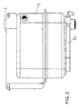
- FIG 2 it is represented the tank 1, the boiler 5, being both surfaces in direct contact one to each other, both upper surface and one sidewall surface.
- Figure 3 is a view of the tank 1 and boiler 5, being foreseen elevator elements that locate the tank 1 in the surrounding area of the boiler 5.
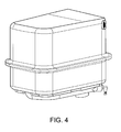
- FIG. 4 shows a boiler 5.
- first of all the tank 1 extends on the totality or most of the upper surface of the boiler 5.
- the tank 1 is filled of water 15, over the level sensor 20, in where water 15, as a consequence of the nearness of the boiler 5 (figure 3) or for the fact to be in contact with the boiler (figure 2) is heated up, by the heat transfer of the referred boiler 5.
- the water fills up the first pipe 3 until the pump 2.
- the pump 2 When it receives the order from the processor 10, the pump 2 pumps a predetermined amount of water through the second pipe 4, by the upper part of one of the sidewalls of the boiler 5.
- Water 16 of the boiler is heated up, by means of the heating means 19, until produces water steam, leaving by the third pipe 6 until it arrives its purpose, for example, in a steam iron 7.
- Predetermined amounts are mentioned, because what is wanted is to minimize the thermal shock. It is also obtained by means of the entrance of the water lower than water level of the boiler, minimizing in this way the cooling and the steam condensation that could take place if this water were introduced directly in the steam chamber of the boiler 5, and finally when entering predetermined amounts, amounts not very great, in order to avoid to make cooler the water 16 of the boiler.
- the level sensor 20 is located in at least one of the inner walls of tank 1, below to the water level 15 inside of the tank, and in lower half of the tank. This sensor 20 is connected to a processor 10 that, when it is informed of the lack of water by the referred level sensor 20, the ironing centre is blocked, preventing the exit of more water steam 17 from the boiler 5.
- the mentioned level sensor 20 consists of two electrical terminals that use water 15 like conductor, and that, as a consequence of the lack of this conductive liquid, sends a signal to the processor 10 informing that circuit is opened as a consequence of the lack of water in tank 1, the referred processor 10 interrupting the ironing centre, as it has been explained previously.
- the processor 10 sends a warning signal in order to activate visual and/or acoustic means, in order that the user realizes it.
- the present invention tries to minimize the thermal shock by means of three ways: first way is to put the tank 1 over the boiler 5, to produce a pre-heating of the water 15 of the tank 1; second way by means of the lower entrance of the water to the boiler 5; and, finally, third way, by means of the entrance or introduction of small amounts, depending on the capacity of the boiler, to avoid the cooling of the existing water inside of the indicated boiler.
- FIG. 2 shows a tank 1 that permits the heat transference by means of the contact with boiler 5, for example, because they, the boiler and tank, are manufactured in metallic materials.
Landscapes
- Engineering & Computer Science (AREA)
- Health & Medical Sciences (AREA)
- Public Health (AREA)
- Textile Engineering (AREA)
- Life Sciences & Earth Sciences (AREA)
- Sustainable Development (AREA)
- Sustainable Energy (AREA)
- Physics & Mathematics (AREA)
- Thermal Sciences (AREA)
- Mechanical Engineering (AREA)
- General Engineering & Computer Science (AREA)
- Irons (AREA)
Priority Applications (1)
| Application Number | Priority Date | Filing Date | Title |
|---|---|---|---|
| EP03380311A EP1555480A1 (de) | 2003-12-31 | 2003-12-31 | Druckaufgeladener Dampferzeuger |
Applications Claiming Priority (1)
| Application Number | Priority Date | Filing Date | Title |
|---|---|---|---|
| EP03380311A EP1555480A1 (de) | 2003-12-31 | 2003-12-31 | Druckaufgeladener Dampferzeuger |
Publications (1)
| Publication Number | Publication Date |
|---|---|
| EP1555480A1 true EP1555480A1 (de) | 2005-07-20 |
Family
ID=34610144
Family Applications (1)
| Application Number | Title | Priority Date | Filing Date |
|---|---|---|---|
| EP03380311A Withdrawn EP1555480A1 (de) | 2003-12-31 | 2003-12-31 | Druckaufgeladener Dampferzeuger |
Country Status (1)
| Country | Link |
|---|---|
| EP (1) | EP1555480A1 (de) |
Cited By (1)
| Publication number | Priority date | Publication date | Assignee | Title |
|---|---|---|---|---|
| EP3783145A1 (de) * | 2019-08-22 | 2021-02-24 | Seb S.A. | Elektrohaushaltsgerät, das einen behälter zur dampfdruckerzeugung umfasst |
Citations (6)
| Publication number | Priority date | Publication date | Assignee | Title |
|---|---|---|---|---|
| US2478569A (en) * | 1945-03-08 | 1949-08-09 | Cooper Harry Peter | Steam generator |
| US3977198A (en) * | 1975-03-17 | 1976-08-31 | Berry Clyde F | Multiple boiler steam generation system |
| US4399657A (en) * | 1982-04-14 | 1983-08-23 | Berry Clyde F | Steam generation system |
| US4937430A (en) * | 1987-10-09 | 1990-06-26 | Termozeta Elettrodomestici S.P.A. | Utility steam generator with self-controlled pressure more particularly for little household electric appliances |
| EP0795720A1 (de) * | 1996-03-13 | 1997-09-17 | Femix di Giannelli Stefano | Elektrisches Haushaltgerät für Dampferzeugung |
| FR2804136A1 (fr) * | 2000-01-20 | 2001-07-27 | Seb Sa | Fer a vapeur a recharge d'eau chaude sous pression |
-
2003
- 2003-12-31 EP EP03380311A patent/EP1555480A1/de not_active Withdrawn
Patent Citations (6)
| Publication number | Priority date | Publication date | Assignee | Title |
|---|---|---|---|---|
| US2478569A (en) * | 1945-03-08 | 1949-08-09 | Cooper Harry Peter | Steam generator |
| US3977198A (en) * | 1975-03-17 | 1976-08-31 | Berry Clyde F | Multiple boiler steam generation system |
| US4399657A (en) * | 1982-04-14 | 1983-08-23 | Berry Clyde F | Steam generation system |
| US4937430A (en) * | 1987-10-09 | 1990-06-26 | Termozeta Elettrodomestici S.P.A. | Utility steam generator with self-controlled pressure more particularly for little household electric appliances |
| EP0795720A1 (de) * | 1996-03-13 | 1997-09-17 | Femix di Giannelli Stefano | Elektrisches Haushaltgerät für Dampferzeugung |
| FR2804136A1 (fr) * | 2000-01-20 | 2001-07-27 | Seb Sa | Fer a vapeur a recharge d'eau chaude sous pression |
Cited By (3)
| Publication number | Priority date | Publication date | Assignee | Title |
|---|---|---|---|---|
| EP3783145A1 (de) * | 2019-08-22 | 2021-02-24 | Seb S.A. | Elektrohaushaltsgerät, das einen behälter zur dampfdruckerzeugung umfasst |
| FR3100036A1 (fr) * | 2019-08-22 | 2021-02-26 | Seb S.A. | Appareil électroménager comportant une cuve pour la génération de vapeur sous pression. |
| CN112411154A (zh) * | 2019-08-22 | 2021-02-26 | Seb公司 | 包括用于产生加压蒸汽的槽的家电设备 |
Similar Documents
| Publication | Publication Date | Title |
|---|---|---|
| CN101646822B (zh) | 用于确定锅炉中的液位的方法 | |
| US6577817B2 (en) | Water heater | |
| US5881207A (en) | Steam generator with automatic supply and a process for measuring the level of liquid in such a generator | |
| CN102755102A (zh) | 蒸汽烹饪设备及水位传感器控制方法 | |
| KR102526714B1 (ko) | 세탁기 | |
| KR102275111B1 (ko) | 워터 서버 및 워터 서버용의 서버 트레이 | |
| KR20120110314A (ko) | 난방 및 온수보일러 | |
| CN102187151B (zh) | 配备有可填充式蒸汽锅炉的家用设备和用于家用设备的蒸汽锅炉 | |
| EP1555480A1 (de) | Druckaufgeladener Dampferzeuger | |
| JP2000329407A (ja) | 熱交換装置 | |
| KR102382430B1 (ko) | 비데용 온수탱크 및 이를 포함하는 비데 장치 | |
| JP2006112746A (ja) | 蒸気発生装置 | |
| CN106016437A (zh) | 热水垫 | |
| CN104120598A (zh) | 蒸汽电烫斗 | |
| GB2375594A (en) | Water heater pipe insulation | |
| EP1553342A1 (de) | Druckaufgeladener Dampferzeuger | |
| KR910008350A (ko) | 순간온수 가열장치 | |
| KR101033268B1 (ko) | 간접 가열방식 구조를 갖는 온수매트용 온수히터 | |
| KR20180007868A (ko) | 온수매트용 온수보일러 | |
| KR20160145048A (ko) | 워터 서버 | |
| MX2007014349A (es) | Diseño de inserto de orificio lateral para calentador de agua. | |
| KR101762240B1 (ko) | 가열기용 열매체유 순환 공급분배기 | |
| JP3325874B2 (ja) | 衛生洗浄装置の瞬間加熱式熱交換装置 | |
| JP2007247945A (ja) | 給湯装置 | |
| US6546944B1 (en) | Fluid siphon outlet sensor system |
Legal Events
| Date | Code | Title | Description |
|---|---|---|---|
| PUAI | Public reference made under article 153(3) epc to a published international application that has entered the european phase |
Free format text: ORIGINAL CODE: 0009012 |
|
| AK | Designated contracting states |
Kind code of ref document: A1 Designated state(s): AT BE BG CH CY CZ DE DK EE ES FI FR GB GR HU IE IT LI LU MC NL PT RO SE SI SK TR |
|
| AX | Request for extension of the european patent |
Extension state: AL LT LV MK |
|
| AKX | Designation fees paid | ||
| REG | Reference to a national code |
Ref country code: DE Ref legal event code: 8566 |
|
| STAA | Information on the status of an ep patent application or granted ep patent |
Free format text: STATUS: THE APPLICATION IS DEEMED TO BE WITHDRAWN |
|
| 18D | Application deemed to be withdrawn |
Effective date: 20060121 |