EP1555463B1 - Getriebesteuerungseinrichtung, insbesondere für Fahrzeuge - Google Patents
Getriebesteuerungseinrichtung, insbesondere für Fahrzeuge Download PDFInfo
- Publication number
- EP1555463B1 EP1555463B1 EP05290045A EP05290045A EP1555463B1 EP 1555463 B1 EP1555463 B1 EP 1555463B1 EP 05290045 A EP05290045 A EP 05290045A EP 05290045 A EP05290045 A EP 05290045A EP 1555463 B1 EP1555463 B1 EP 1555463B1
- Authority
- EP
- European Patent Office
- Prior art keywords
- coil
- gearbox
- flat
- selector shaft
- sensor
- Prior art date
- Legal status (The legal status is an assumption and is not a legal conclusion. Google has not performed a legal analysis and makes no representation as to the accuracy of the status listed.)
- Expired - Lifetime
Links
Images


Classifications
-
- F—MECHANICAL ENGINEERING; LIGHTING; HEATING; WEAPONS; BLASTING
- F16—ENGINEERING ELEMENTS AND UNITS; GENERAL MEASURES FOR PRODUCING AND MAINTAINING EFFECTIVE FUNCTIONING OF MACHINES OR INSTALLATIONS; THERMAL INSULATION IN GENERAL
- F16H—GEARING
- F16H61/00—Control functions within control units of change-speed- or reversing-gearings for conveying rotary motion ; Control of exclusively fluid gearing, friction gearing, gearings with endless flexible members or other particular types of gearing
- F16H61/26—Generation or transmission of movements for final actuating mechanisms
- F16H61/28—Generation or transmission of movements for final actuating mechanisms with at least one movement of the final actuating mechanism being caused by a non-mechanical force, e.g. power-assisted
- F16H61/32—Electric motors , actuators or related electrical control means therefor
-
- H—ELECTRICITY
- H02—GENERATION; CONVERSION OR DISTRIBUTION OF ELECTRIC POWER
- H02K—DYNAMO-ELECTRIC MACHINES
- H02K41/00—Propulsion systems in which a rigid body is moved along a path due to dynamo-electric interaction between the body and a magnetic field travelling along the path
- H02K41/02—Linear motors; Sectional motors
- H02K41/035—DC motors; Unipolar motors
- H02K41/0352—Unipolar motors
- H02K41/0354—Lorentz force motors, e.g. voice coil motors
- H02K41/0358—Lorentz force motors, e.g. voice coil motors moving along a curvilinear path
-
- F—MECHANICAL ENGINEERING; LIGHTING; HEATING; WEAPONS; BLASTING
- F16—ENGINEERING ELEMENTS AND UNITS; GENERAL MEASURES FOR PRODUCING AND MAINTAINING EFFECTIVE FUNCTIONING OF MACHINES OR INSTALLATIONS; THERMAL INSULATION IN GENERAL
- F16H—GEARING
- F16H59/00—Control inputs to control units of change-speed- or reversing-gearings for conveying rotary motion
- F16H59/68—Inputs being a function of gearing status
- F16H2059/6807—Status of gear-change operation, e.g. clutch fully engaged
-
- F—MECHANICAL ENGINEERING; LIGHTING; HEATING; WEAPONS; BLASTING
- F16—ENGINEERING ELEMENTS AND UNITS; GENERAL MEASURES FOR PRODUCING AND MAINTAINING EFFECTIVE FUNCTIONING OF MACHINES OR INSTALLATIONS; THERMAL INSULATION IN GENERAL
- F16H—GEARING
- F16H61/00—Control functions within control units of change-speed- or reversing-gearings for conveying rotary motion ; Control of exclusively fluid gearing, friction gearing, gearings with endless flexible members or other particular types of gearing
- F16H61/26—Generation or transmission of movements for final actuating mechanisms
- F16H61/28—Generation or transmission of movements for final actuating mechanisms with at least one movement of the final actuating mechanism being caused by a non-mechanical force, e.g. power-assisted
- F16H2061/2823—Controlling actuator force way characteristic, i.e. controlling force or movement depending on the actuator position, e.g. for adapting force to synchronisation and engagement of gear clutch
-
- F—MECHANICAL ENGINEERING; LIGHTING; HEATING; WEAPONS; BLASTING
- F16—ENGINEERING ELEMENTS AND UNITS; GENERAL MEASURES FOR PRODUCING AND MAINTAINING EFFECTIVE FUNCTIONING OF MACHINES OR INSTALLATIONS; THERMAL INSULATION IN GENERAL
- F16H—GEARING
- F16H63/00—Control outputs from the control unit to change-speed- or reversing-gearings for conveying rotary motion or to other devices than the final output mechanism
- F16H63/02—Final output mechanisms therefor; Actuating means for the final output mechanisms
- F16H63/30—Constructional features of the final output mechanisms
- F16H63/304—Constructional features of the final output mechanisms the final output mechanisms comprising elements moved by electrical or magnetic force
- F16H2063/305—Constructional features of the final output mechanisms the final output mechanisms comprising elements moved by electrical or magnetic force using electromagnetic solenoids
-
- F—MECHANICAL ENGINEERING; LIGHTING; HEATING; WEAPONS; BLASTING
- F16—ENGINEERING ELEMENTS AND UNITS; GENERAL MEASURES FOR PRODUCING AND MAINTAINING EFFECTIVE FUNCTIONING OF MACHINES OR INSTALLATIONS; THERMAL INSULATION IN GENERAL
- F16H—GEARING
- F16H63/00—Control outputs from the control unit to change-speed- or reversing-gearings for conveying rotary motion or to other devices than the final output mechanism
- F16H63/02—Final output mechanisms therefor; Actuating means for the final output mechanisms
- F16H63/30—Constructional features of the final output mechanisms
- F16H63/304—Constructional features of the final output mechanisms the final output mechanisms comprising elements moved by electrical or magnetic force
Definitions
- the present invention relates to a control device of an automatic gearbox, in particular for a motor vehicle, comprising means for actuating at least one selection axis rotatably mounted in the gearbox.
- Document FR-A-2,839,216 shows a control device comprising all the features of the preamble of independent claim 1.
- the selection lever is connected to the gearbox by a cable system or a linkage, the disadvantages of which are well known.
- the present invention particularly relates to a control device of a gearbox which does not have the disadvantages of known devices.
- a control device of an automatic gearbox in particular for a motor vehicle, comprising means for actuating at least one selection axis rotatably mounted in the gearbox, characterized in that the actuating means are formed by a flat electrical actuator comprising a flat coil mounted to rotate about a fixed axis between two flat permanent magnets carried by a yoke, connecting means connecting the coil to the axis of selection of the gearbox, and power supply means of the coil, suitable for causing a electrical current in one direction or the other in the coil to rotate it in one direction or the other around the aforementioned fixed axis.
- the device according to the invention considerably reduces the friction and the risk of blockage because it does not include gears or sliding cables or linkage.
- it is reversible, which allows to control the actuator with a relative accuracy because it is no longer necessary to bring the selection axis exactly in a predetermined position. It is sufficient to bring this axis close to its predetermined position, after which angular positioning means such as blasting means or the like associated with the selection axis act on this axis and bring it to its exact position of selection. , the reversibility of the drive by the actuator allowing this movement without upsetting it.
- the response time of such a control device is low, typically of the order of 70ms.
- the device comprises means for controlling the electrical power supply of the coil, in order to pass an electric current through a coil in a determined direction for a determined period of time as a function of electrical signals generated by control means controlled by switching means associated with the gear selection lever.
- the control of the power supply means of the coil can thus be performed in a particularly simple and reliable manner.
- the device comprises a position or displacement sensor associated with the coil and providing a signal corresponding to the angular displacement of the coil about the aforementioned fixed axis, this sensor being mounted in a loop of reaction of the control means of the power supply of the coil.
- the senor is of the non-contact type, such as for example a magnetoresistor sensor.
- Such a sensor is insensitive to the temperature variations of the permanent magnets and has a good resistance to vibrations. In addition, it provides a signal proportional to the angular displacement of the coil about its axis of rotation.
- the coil is mounted directly on the selection axis of the gearbox, which forms the axis of rotation of the coil.
- the coil is connected to the selection axis of the gearbox by at least one lever comprising length adjustment means.
- the adjustment means make it possible to angularly preposition the flat coil with precision, compensating for and catching the dimensional dispersions and the dimensional tolerances.
- the power supply means of the coil comprise a DC converter or DC-DC converter according to the terminology used in general.
- the selection axis of the gearbox is associated with an angular positioning means such as an elastic billing blade ensuring accurate positioning of this axis in each of its predetermined angular positions. speed selection.
- the permanent magnets of the actuating means are neodymium iron boron magnets.
- neodymium iron boron magnets guarantees temperature and demagnetization performance.
- the permanent magnets of the actuating means are samarium cobalt magnets.
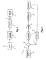
- reference numeral 1 designates speed selection means such as a lever intended to drive in rotation a selection axis 3 of an automatic gearbox 2 of a motor vehicle.
- the selection lever 1 is actuated by the driver of the vehicle and moved in a grid at several predetermined positions of the PRND type for example, the disposition of the lever in one of these positions actuating a switch whose output signal is transmitted to a control circuit 4.
- the control circuit 4 generates a control signal of an actuator 5 which rotates the selection axis 3 in one direction or in the other, to bring it to a predetermined position corresponding to that of the lever 1.
- the control circuit 4 shown in more detail in FIG. 2, comprises a management module 6 controlled by the vehicle computer and generating a setpoint signal applied by a corrector 7 and by an amplifier 8 to means 9 for power supply. of the actuator 5.
- a position or displacement sensor 10 is associated with the output of the actuator 5 and generates an electrical signal 11 applied to an input of a comparator 12 whose other input receives the reference signal 13 supplied by the management module 6
- the output of the comparator 12 represents the difference of the signals 11 and 13 and is applied by the corrector 7 and the amplifier 8 to the means 9 which generate an electric current whose intensity, polarity and duration are determined.
- the actuator 5 is a flat electric motor and in one embodiment shown in FIG. 3 comprises a flat coil 14 in the form of an angular sector rotatably mounted, by means of a bushing 15, around a fixed axis 16.
- Flat electrical actuators of this type are known, in particular from French Patent No. 2,638,273 which describes a flat electric motor consisting of a juxtaposition of flat coils mounted sliding on slides and separated by permanent magnets.
- the power supply of the coils induces a magnetic field which opposes the polarization of the permanent magnets and creates a lateral displacement of the coils along their slides.
- the flat coil 14 of the actuator of the device according to the invention is movable in rotation between two flat permanent magnets 17 and 18 fixed and carried by a yoke (not shown) closing the magnetic field.
- the flat permanent magnets 17 and 18 are preferably neodymium iron boron magnets or samarium cobalt magnets.
- the flat coil 14 extends angularly about 45 ° and comprises from 90 to 120 turns of copper wire with a diameter of about 1 mm.
- the electrical resistance of this coil is between about 0.3 and 0.9 ohms at 25 ° C. Its inductance is between 0.3 and 0.9 mH.
- the thickness of the copper wire windings is about 8 mm.
- the flat magnets 17,18 extend angularly each about 90 °. They generate a magnetic field of about 1.1 to 1.2 T and have a coercive field strength (demagnetization) of about 900 to 2000 KA / m. Their thickness is of the order of 5 to 10 mm.
- each magnet 17, 18 extending over 90 °, two substantially juxtaposed magnets each extending over 45 °.
- the power supply means 9 pass through the coil 14 an electric current of determined duration in a given direction.
- the power supply means 9 of the actuator 5 preferably comprise a DC converter or DC-DC converter in order, in particular, to reduce the operating intensities, the response time of the actuator and the Joule losses.
- the angular displacements of the coil 14 are detected by a position or displacement sensor 19 carried by the sleeve 15 and rotating with respect to the permanent magnet 18 to provide a signal corresponding to a rotation of the coil 14 about the axis
- the sensor 19 is of the non-contact type, for example a magnetoresistor sensor, the structure of which is described in more detail in the following with reference to FIG.
- the sleeve 15 of the coil 14 can be connected to the selection axis 3 of the gearbox in different ways.
- connection means comprise a lever 20 or 21 integral in rotation with the sleeve 15 of the coil and connected at its other end by a link 22 or 23 to another lever 24 or 25, the other of which end is integral in rotation with the gearbox selection axis.
- the link 22 comprises length adjustment means 26, which make it possible to adjust the angular position of the coil 14 with respect to a determined position of the selection axis 3 by compensating for the odds dispersion and the tolerances.
- the adjustment means 26 are of any suitable type and comprise for example a nut screwed onto a threaded rod and means for locking the nut in rotation.
- the compensation by the means 26 is for example of the order of 10 mm in length and corresponds to an angular difference of plus or minus 0.7 ° at the actuator.
- the selection axis 3 of the gearbox 2 is preferably associated with a billing blade which ensures precise positioning of this axis in any predetermined angular positions PRND as soon as the axis 3 is in the vicinity of this axis. position.
- the actuator does not bring the axis 3 into its predetermined position, but brings it to a similar position, the billing blade finishes positioning the axis 3. results in great safety of the order.
- the actuator of Figures 4 and 5 is housed in a protective housing formed by the assembly of two housings 27, 28 which can serve as a mounting yoke of the permanent magnets 17, 18 above.
- FIG. 6 diagrammatically shows a magnetoresistance sensor comprising four sensitive elements 29 to 32 of ferrous material, for example, mounted in a Wheatstone bridge, two opposite terminals 33, 34 of which are connected to a power supply source Vs and whose the other two terminals 35, 36 form the output terminals of the sensor, between which an output voltage ⁇ V is generated.
- this output voltage ⁇ V is applied to an input of the comparator 12.
- the electrical resistances R1, R2, R3, R4 of the sensitive elements 29 to 32 vary as a function of the angle between, on the one hand, the magnetization produced in the sensitive elements 29 to 32 by a magnetic induction M generated by the permanent magnet 18 of Figure 3 and on the other hand the direction of the passage of the electric current in the sensitive elements 29 to 32.
- the sensitive elements 29 to 32 are magnetically saturated and their resistances R1, R2, R3, R4 vary according to the square of the cosine of the angle between the magnetic induction M and the direction of passage of the electric current in the elements 29 at 32.
- the invention also applies to the control of a gearbox comprising a selection and engagement axis, the device then comprising two actuators of the aforementioned type for displacements of the axis in translation and in translation. rotation.
Landscapes
- Engineering & Computer Science (AREA)
- General Engineering & Computer Science (AREA)
- Electromagnetism (AREA)
- Physics & Mathematics (AREA)
- Chemical & Material Sciences (AREA)
- Combustion & Propulsion (AREA)
- Mechanical Engineering (AREA)
- Power Engineering (AREA)
- Gear-Shifting Mechanisms (AREA)
- Reciprocating, Oscillating Or Vibrating Motors (AREA)
- Connection Of Motors, Electrical Generators, Mechanical Devices, And The Like (AREA)
- Control Of Transmission Device (AREA)
- Windings For Motors And Generators (AREA)
- Permanent Field Magnets Of Synchronous Machinery (AREA)
Claims (10)
- Steuerungseinrichtung für ein Automatikgetriebe (2), insbesondere für ein Kraftfahrzeug, umfassend Betätigungsmittel mindestens einer Auswahlachse (3), die drehbar im Getriebe (2) angebracht ist, dadurch gekennzeichnet, dass die Betätigungsmittel zur Rotation der Auswahlachse (3) durch einen flachen Elektroantrieb (5) gebildet sind, der eine flache Spule (14) umfasst, die drehbar um eine feste Achse (16) zwischen zwei flachen Permanentmagneten (17, 18) angebracht ist, die von einem Joch getragen sind, wobei Verbindungsmittel (15, 20 bis 25) die Spule (14) mit der Auswahlachse (3) des Getriebes (2) verbinden, und Mittel (9) zur elektrischen Stromversorgung der Spule (14), die gegeignet sind, einen elektrischen Strom in der einen oder anderen Richtung in der Spule (14) fließen zu lassen, damit sie sich in der einen oder anderen Richtung um die genannte feste Achse (16) dreht.
- Einrichtung nach Anspruch 1, dadurch gekennzeichnet, dass sie Steuerungsmittel (4) für die elektrische Stromversorgung der Spule (14) umfasst, um in der Spule (14) einen elektrischen Strom in einer bestimmten Richtung während einer bestimmten Dauer in Funktion von elektrischen Signalen, die von Schaltwahlmitteln (1) erzeugt sind, fließen zu lassen.
- Einrichtung nach Anspruch 2, dadurch gekennzeichnet, dass sie einen Sensor (19) für die Position oder Verschiebung der Spule (14) umfasst und ein Signal gibt, das einer Winkelverschiebung der Spule (14) um die genannte feste Achse (16) entspricht, wobei dieser Sensor (19) in einer Reaktionsschleife der Steuermittel (4) für die elektrische Stromversorgung der Spule (14) angebracht ist.
- Einrichtung nach Anspruch 3, dadurch gekennzeichnet, dass der Sensor (19) vom kontaktlosen Typ ist, wie zum Beispiel ein Magnetwiderstandssensor (29 bis 32).
- Einrichtung nach einem der vorhergehenden Ansprüche, dadurch gekennzeichnet, dass die Spule (14) auf der Auswahlachse (3) des Getriebes (2) angebracht ist, die die Rotationsachse der Spule (14) bildet.
- Einrichtung nach einem der Ansprüche 1 bis 4, dadurch gekennzeichnet, dass die Spule (14) mit der Auswahlachse (3) des Getriebes (2) durch mindestens ein Schaltgestänge (22, 23) verbunden ist, das zum Beispiel Längenregelungsmittel (26) umfasst.
- Einrichtung nach einem der vorhergehenden Ansprüche, dadurch gekennzeichnet, dass die elektrischen Stromversorgungsmittel (9) der Spule (14) einen DC-DC-Wandler umfassen.
- Einrichtung nach einem der vorhergehenden Ansprüche, dadurch gekennzeichnet, dass sie reversibel ist und dadurch, dass der Auswahlachse (3) des Getriebes (2) ein Winkelpositionierungsmittel zugeordnet ist, wie ein elastisches Stellelement, das eine Positionierung dieser Achse (3) in irgendeiner von mehreren bestimmten Winkelpositionen gewährleistet.
- Einrichtung nach einem der vorhergehenden Ansprüche, dadurch gekennzeichnet, dass die Permanentmagneten (17, 18) der Betätigungsmittel Neodymeisenbormagneten sind.
- Einrichtung nach einem der vorhergehenden Ansprüche, dadurch gekennzeichnet, dass die Permanentmagneten (17, 18) der Betätigungsmittel Samariumcobaltmagneten sind.
Applications Claiming Priority (2)
| Application Number | Priority Date | Filing Date | Title |
|---|---|---|---|
| FR0400372A FR2865164B1 (fr) | 2004-01-15 | 2004-01-15 | Dispositif de commande d'une boite de vitesses, en particulier pour vehicule automobile |
| FR0400372 | 2004-01-15 |
Publications (2)
| Publication Number | Publication Date |
|---|---|
| EP1555463A1 EP1555463A1 (de) | 2005-07-20 |
| EP1555463B1 true EP1555463B1 (de) | 2006-09-20 |
Family
ID=34610776
Family Applications (1)
| Application Number | Title | Priority Date | Filing Date |
|---|---|---|---|
| EP05290045A Expired - Lifetime EP1555463B1 (de) | 2004-01-15 | 2005-01-07 | Getriebesteuerungseinrichtung, insbesondere für Fahrzeuge |
Country Status (8)
| Country | Link |
|---|---|
| US (1) | US20050184598A1 (de) |
| EP (1) | EP1555463B1 (de) |
| JP (1) | JP2005204498A (de) |
| CN (1) | CN1664418A (de) |
| AT (1) | ATE340319T1 (de) |
| DE (1) | DE602005000130T2 (de) |
| ES (1) | ES2273317T3 (de) |
| FR (1) | FR2865164B1 (de) |
Families Citing this family (6)
| Publication number | Priority date | Publication date | Assignee | Title |
|---|---|---|---|---|
| FR2888627A1 (fr) | 2005-07-13 | 2007-01-19 | Teleflex Automotive France Sa | Dispositif de commande d'une boite de vitesses, en particulier pour vehicule automobile |
| FR2910739B1 (fr) * | 2006-12-21 | 2009-03-06 | Teleflex Automotive France Sas | Actionneur electrique, en particulier pour l'entrainement d'un arbre de selection d'une boite de vitesses. |
| CN103671871A (zh) * | 2013-12-25 | 2014-03-26 | 盛瑞传动股份有限公司 | 一种自动变速器用换挡装置 |
| CN103671906B (zh) * | 2013-12-25 | 2016-02-10 | 盛瑞传动股份有限公司 | 一种自动变速箱用挡位传感装置 |
| KR101499224B1 (ko) * | 2014-04-01 | 2015-03-11 | 현대자동차주식회사 | 부채형 전자식 변속레버 |
| EP4650074A1 (de) * | 2024-05-16 | 2025-11-19 | Kocks Technik GmbH&Co. KG | Walzblock |
Family Cites Families (14)
| Publication number | Priority date | Publication date | Assignee | Title |
|---|---|---|---|---|
| JPS59113762A (ja) * | 1982-12-17 | 1984-06-30 | Matsushita Electric Ind Co Ltd | 円弧モ−タ |
| FR2638273B1 (fr) | 1988-10-13 | 1991-01-18 | Acroe | Assemblage de modules actionneurs lineaires plats |
| JPH06178524A (ja) * | 1992-12-04 | 1994-06-24 | Hitachi Metals Ltd | ボイスコイル型モータ |
| JP3422002B2 (ja) * | 1994-11-11 | 2003-06-30 | 株式会社小松製作所 | Dc−dcコンバータ回路およびこのdc−dcコンバータ回路を用いた誘導負荷駆動装置 |
| US6437770B1 (en) * | 1998-01-26 | 2002-08-20 | University Of Washington | Flat-coil actuator having coil embedded in linkage |
| US6157099A (en) * | 1999-01-15 | 2000-12-05 | Quantum Corporation | Specially oriented material and magnetization of permanent magnets |
| DE50113489D1 (de) * | 2000-07-14 | 2008-03-06 | Trw Automotive Electron & Comp | Betätigungsvorrichtung für die Schaltwelle eines Automatikgetriebes |
| DE10044159B4 (de) * | 2000-09-06 | 2009-12-31 | ZF Lemförder GmbH | Vorrichtung zum Umschaltung eines mechanischen Schaltmittels zwischen einem ersten Schaltzustand und wenigstens einem zweiten Schaltzustand |
| DE60226284T2 (de) * | 2001-01-22 | 2009-05-20 | Isuzu Motors Ltd. | Schaltaktuator für Getriebe |
| US6877390B2 (en) * | 2002-02-28 | 2005-04-12 | Aisin Aw Co., Ltd. | Shift range changeover mechanism |
| ITMI20030716A1 (it) * | 2002-04-10 | 2003-10-11 | Luk Lamellen & Kupplungsbau | Disposizione del motore con un supporto fisso. |
| FR2839216B1 (fr) * | 2002-04-26 | 2005-06-24 | Renault Sa | Actionneur lineaire notamment pour boite de vitesses robotisee |
| FR2839132B1 (fr) * | 2002-04-26 | 2004-11-19 | Renault Sa | Actionneur pour boite de vitesses robotisee et boite de vitesses robotisee comprenant un tel actionneur |
| US6850140B1 (en) * | 2003-09-10 | 2005-02-01 | Magnetic Technologies Corporation | Layered magnets and methods for producing same |
-
2004
- 2004-01-15 FR FR0400372A patent/FR2865164B1/fr not_active Expired - Fee Related
-
2005
- 2005-01-07 AT AT05290045T patent/ATE340319T1/de not_active IP Right Cessation
- 2005-01-07 DE DE602005000130T patent/DE602005000130T2/de not_active Expired - Fee Related
- 2005-01-07 EP EP05290045A patent/EP1555463B1/de not_active Expired - Lifetime
- 2005-01-07 ES ES05290045T patent/ES2273317T3/es not_active Expired - Lifetime
- 2005-01-13 US US11/034,658 patent/US20050184598A1/en not_active Abandoned
- 2005-01-14 JP JP2005008362A patent/JP2005204498A/ja active Pending
- 2005-01-14 CN CN200510004099.3A patent/CN1664418A/zh active Pending
Also Published As
| Publication number | Publication date |
|---|---|
| CN1664418A (zh) | 2005-09-07 |
| US20050184598A1 (en) | 2005-08-25 |
| JP2005204498A (ja) | 2005-07-28 |
| DE602005000130T2 (de) | 2007-09-06 |
| DE602005000130D1 (de) | 2006-11-02 |
| FR2865164A1 (fr) | 2005-07-22 |
| FR2865164B1 (fr) | 2006-04-07 |
| EP1555463A1 (de) | 2005-07-20 |
| ES2273317T3 (es) | 2007-05-01 |
| ATE340319T1 (de) | 2006-10-15 |
Similar Documents
| Publication | Publication Date | Title |
|---|---|---|
| EP1555463B1 (de) | Getriebesteuerungseinrichtung, insbesondere für Fahrzeuge | |
| WO2012101122A1 (fr) | Dispositif d'actionnement d'un equipement pilotable automatiquement ou manuellement avec detection de la reprise du pilotage manuel | |
| EP2779372B1 (de) | Elektromechanisches Stellglied für Bremse | |
| FR2831345A1 (fr) | Machine electrique a defluxage mecanique | |
| FR2614362A1 (fr) | Dispositif de reglage d'un papillon de gaz pour regulation du glissement de traction ou de la vitesse | |
| FR2614586A1 (fr) | Dispositif de commande d'orientation pour projecteurs de vehicule automobile | |
| FR2595840A1 (fr) | Dispositif pour la regulation de la traction et de la vitesse d'un vehicule automobile | |
| FR3072518A1 (fr) | Dispositif mecatronique pour l'actionnement d'un dispositif de freinage, frein a disque et procede de freinage associes | |
| FR2517845A1 (fr) | Mecanisme a encliquetage de maintien et liberation | |
| EP0790442A1 (de) | Regelungssystem für den Schalthebel eines Getriebes von Kraftfahrzeugen | |
| EP4244962A1 (de) | Bistabiler elektromagnetischer aktuator und flugzeugbremsventil mit solch einem aktuator | |
| EP1467479B1 (de) | Antriebsvorrichtung für ein Schliesselement | |
| EP4146509B1 (de) | Manuell betätigter elektromagnetischer aktuator und mit einem solchen aktuator ausgestattetes parkbremsventil | |
| EP4355654B1 (de) | Flugkompensator für flugzeug | |
| EP3729618B1 (de) | Stellantrieb mit steuerdirektantrieb mit offener schleife | |
| EP0651704B1 (de) | Vorrichtung zum steuern von positionen von bewegungsachsen | |
| EP1798524B1 (de) | Winkelpositionssensor | |
| FR2744559A1 (fr) | Actionneur electromagnetique monophase rotatif a ressort magnetique et vanne electrique mettant en oeuvre un tel actionneur | |
| FR2822253A1 (fr) | Dispositif de commande a retour d'effort pour vehicule automobile | |
| FR3058750A1 (fr) | Systeme de commande d’ouverture et de fermeture d’un ouvrant d’un vehicule, notamment automobile | |
| WO2004056630A1 (fr) | Dispositif de commande electrique d'un frein de parking pour vehicule automobile | |
| FR2888627A1 (fr) | Dispositif de commande d'une boite de vitesses, en particulier pour vehicule automobile | |
| GB2413375A (en) | Direction and speed control device for a motor vehicle with magnets movable on either side of a sensor | |
| EP0514234A1 (de) | Elektrischer Steuerungswähler zur Führung von mindestens einem beweglichen Stellglied in diskreten Stellungen | |
| FR2981745A1 (fr) | Capteur destine a detecter le deplacement d'un objet mobile par rapport a un autre objet |
Legal Events
| Date | Code | Title | Description |
|---|---|---|---|
| PUAI | Public reference made under article 153(3) epc to a published international application that has entered the european phase |
Free format text: ORIGINAL CODE: 0009012 |
|
| AK | Designated contracting states |
Kind code of ref document: A1 Designated state(s): AT BE BG CH CY CZ DE DK EE ES FI FR GB GR HU IE IS IT LI LT LU MC NL PL PT RO SE SI SK TR |
|
| AX | Request for extension of the european patent |
Extension state: AL BA HR LV MK YU |
|
| RIN1 | Information on inventor provided before grant (corrected) |
Inventor name: BAZ, JEAN-PIERRE Inventor name: GUIMET, DANIEL Inventor name: FLORENS, JEAN-LOUP |
|
| 17P | Request for examination filed |
Effective date: 20060120 |
|
| GRAP | Despatch of communication of intention to grant a patent |
Free format text: ORIGINAL CODE: EPIDOSNIGR1 |
|
| AKX | Designation fees paid |
Designated state(s): AT BE BG CH CY CZ DE DK EE ES FI FR GB GR HU IE IS IT LI LT LU MC NL PL PT RO SE SI SK TR |
|
| GRAS | Grant fee paid |
Free format text: ORIGINAL CODE: EPIDOSNIGR3 |
|
| GRAA | (expected) grant |
Free format text: ORIGINAL CODE: 0009210 |
|
| AK | Designated contracting states |
Kind code of ref document: B1 Designated state(s): AT BE BG CH CY CZ DE DK EE ES FI FR GB GR HU IE IS IT LI LT LU MC NL PL PT RO SE SI SK TR |
|
| PG25 | Lapsed in a contracting state [announced via postgrant information from national office to epo] |
Ref country code: AT Free format text: LAPSE BECAUSE OF FAILURE TO SUBMIT A TRANSLATION OF THE DESCRIPTION OR TO PAY THE FEE WITHIN THE PRESCRIBED TIME-LIMIT Effective date: 20060920 Ref country code: CZ Free format text: LAPSE BECAUSE OF FAILURE TO SUBMIT A TRANSLATION OF THE DESCRIPTION OR TO PAY THE FEE WITHIN THE PRESCRIBED TIME-LIMIT Effective date: 20060920 Ref country code: FI Free format text: LAPSE BECAUSE OF FAILURE TO SUBMIT A TRANSLATION OF THE DESCRIPTION OR TO PAY THE FEE WITHIN THE PRESCRIBED TIME-LIMIT Effective date: 20060920 Ref country code: IE Free format text: LAPSE BECAUSE OF FAILURE TO SUBMIT A TRANSLATION OF THE DESCRIPTION OR TO PAY THE FEE WITHIN THE PRESCRIBED TIME-LIMIT Effective date: 20060920 Ref country code: LT Free format text: LAPSE BECAUSE OF FAILURE TO SUBMIT A TRANSLATION OF THE DESCRIPTION OR TO PAY THE FEE WITHIN THE PRESCRIBED TIME-LIMIT Effective date: 20060920 Ref country code: NL Free format text: LAPSE BECAUSE OF FAILURE TO SUBMIT A TRANSLATION OF THE DESCRIPTION OR TO PAY THE FEE WITHIN THE PRESCRIBED TIME-LIMIT Effective date: 20060920 Ref country code: PL Free format text: LAPSE BECAUSE OF FAILURE TO SUBMIT A TRANSLATION OF THE DESCRIPTION OR TO PAY THE FEE WITHIN THE PRESCRIBED TIME-LIMIT Effective date: 20060920 Ref country code: RO Free format text: LAPSE BECAUSE OF FAILURE TO SUBMIT A TRANSLATION OF THE DESCRIPTION OR TO PAY THE FEE WITHIN THE PRESCRIBED TIME-LIMIT Effective date: 20060920 Ref country code: SI Free format text: LAPSE BECAUSE OF FAILURE TO SUBMIT A TRANSLATION OF THE DESCRIPTION OR TO PAY THE FEE WITHIN THE PRESCRIBED TIME-LIMIT Effective date: 20060920 Ref country code: SK Free format text: LAPSE BECAUSE OF FAILURE TO SUBMIT A TRANSLATION OF THE DESCRIPTION OR TO PAY THE FEE WITHIN THE PRESCRIBED TIME-LIMIT Effective date: 20060920 |
|
| REG | Reference to a national code |
Ref country code: GB Ref legal event code: FG4D Free format text: NOT ENGLISH |
|
| REG | Reference to a national code |
Ref country code: CH Ref legal event code: EP |
|
| REG | Reference to a national code |
Ref country code: IE Ref legal event code: FG4D Free format text: LANGUAGE OF EP DOCUMENT: FRENCH |
|
| REF | Corresponds to: |
Ref document number: 602005000130 Country of ref document: DE Date of ref document: 20061102 Kind code of ref document: P |
|
| PG25 | Lapsed in a contracting state [announced via postgrant information from national office to epo] |
Ref country code: DK Free format text: LAPSE BECAUSE OF FAILURE TO SUBMIT A TRANSLATION OF THE DESCRIPTION OR TO PAY THE FEE WITHIN THE PRESCRIBED TIME-LIMIT Effective date: 20061220 Ref country code: BG Free format text: LAPSE BECAUSE OF FAILURE TO SUBMIT A TRANSLATION OF THE DESCRIPTION OR TO PAY THE FEE WITHIN THE PRESCRIBED TIME-LIMIT Effective date: 20061220 |
|
| REG | Reference to a national code |
Ref country code: SE Ref legal event code: TRGR |
|
| PG25 | Lapsed in a contracting state [announced via postgrant information from national office to epo] |
Ref country code: IS Free format text: LAPSE BECAUSE OF FAILURE TO SUBMIT A TRANSLATION OF THE DESCRIPTION OR TO PAY THE FEE WITHIN THE PRESCRIBED TIME-LIMIT Effective date: 20070120 |
|
| GBT | Gb: translation of ep patent filed (gb section 77(6)(a)/1977) |
Effective date: 20070110 |
|
| PG25 | Lapsed in a contracting state [announced via postgrant information from national office to epo] |
Ref country code: MC Free format text: LAPSE BECAUSE OF NON-PAYMENT OF DUE FEES Effective date: 20070131 |
|
| PGFP | Annual fee paid to national office [announced via postgrant information from national office to epo] |
Ref country code: SE Payment date: 20070131 Year of fee payment: 3 |
|
| PGFP | Annual fee paid to national office [announced via postgrant information from national office to epo] |
Ref country code: DE Payment date: 20070209 Year of fee payment: 3 |
|
| PGFP | Annual fee paid to national office [announced via postgrant information from national office to epo] |
Ref country code: ES Payment date: 20070220 Year of fee payment: 3 |
|
| NLV1 | Nl: lapsed or annulled due to failure to fulfill the requirements of art. 29p and 29m of the patents act | ||
| PG25 | Lapsed in a contracting state [announced via postgrant information from national office to epo] |
Ref country code: PT Free format text: LAPSE BECAUSE OF FAILURE TO SUBMIT A TRANSLATION OF THE DESCRIPTION OR TO PAY THE FEE WITHIN THE PRESCRIBED TIME-LIMIT Effective date: 20070312 |
|
| REG | Reference to a national code |
Ref country code: IE Ref legal event code: FD4D |
|
| REG | Reference to a national code |
Ref country code: ES Ref legal event code: FG2A Ref document number: 2273317 Country of ref document: ES Kind code of ref document: T3 |
|
| PLBE | No opposition filed within time limit |
Free format text: ORIGINAL CODE: 0009261 |
|
| STAA | Information on the status of an ep patent application or granted ep patent |
Free format text: STATUS: NO OPPOSITION FILED WITHIN TIME LIMIT |
|
| 26N | No opposition filed |
Effective date: 20070621 |
|
| PGFP | Annual fee paid to national office [announced via postgrant information from national office to epo] |
Ref country code: TR Payment date: 20070117 Year of fee payment: 3 |
|
| BERE | Be: lapsed |
Owner name: TELEFLEX AUTOMOTIVE FRANCE SA Effective date: 20070131 |
|
| PG25 | Lapsed in a contracting state [announced via postgrant information from national office to epo] |
Ref country code: BE Free format text: LAPSE BECAUSE OF NON-PAYMENT OF DUE FEES Effective date: 20070131 |
|
| PG25 | Lapsed in a contracting state [announced via postgrant information from national office to epo] |
Ref country code: GR Free format text: LAPSE BECAUSE OF FAILURE TO SUBMIT A TRANSLATION OF THE DESCRIPTION OR TO PAY THE FEE WITHIN THE PRESCRIBED TIME-LIMIT Effective date: 20061221 |
|
| PGFP | Annual fee paid to national office [announced via postgrant information from national office to epo] |
Ref country code: FR Payment date: 20070131 Year of fee payment: 3 |
|
| PG25 | Lapsed in a contracting state [announced via postgrant information from national office to epo] |
Ref country code: EE Free format text: LAPSE BECAUSE OF FAILURE TO SUBMIT A TRANSLATION OF THE DESCRIPTION OR TO PAY THE FEE WITHIN THE PRESCRIBED TIME-LIMIT Effective date: 20060920 |
|
| EUG | Se: european patent has lapsed | ||
| PG25 | Lapsed in a contracting state [announced via postgrant information from national office to epo] |
Ref country code: DE Free format text: LAPSE BECAUSE OF NON-PAYMENT OF DUE FEES Effective date: 20080801 |
|
| REG | Reference to a national code |
Ref country code: FR Ref legal event code: ST Effective date: 20081029 |
|
| PG25 | Lapsed in a contracting state [announced via postgrant information from national office to epo] |
Ref country code: SE Free format text: LAPSE BECAUSE OF NON-PAYMENT OF DUE FEES Effective date: 20080108 |
|
| REG | Reference to a national code |
Ref country code: ES Ref legal event code: FD2A Effective date: 20080108 |
|
| PG25 | Lapsed in a contracting state [announced via postgrant information from national office to epo] |
Ref country code: FR Free format text: LAPSE BECAUSE OF NON-PAYMENT OF DUE FEES Effective date: 20080131 |
|
| PG25 | Lapsed in a contracting state [announced via postgrant information from national office to epo] |
Ref country code: ES Free format text: LAPSE BECAUSE OF NON-PAYMENT OF DUE FEES Effective date: 20080108 |
|
| PG25 | Lapsed in a contracting state [announced via postgrant information from national office to epo] |
Ref country code: CY Free format text: LAPSE BECAUSE OF FAILURE TO SUBMIT A TRANSLATION OF THE DESCRIPTION OR TO PAY THE FEE WITHIN THE PRESCRIBED TIME-LIMIT Effective date: 20060920 Ref country code: LU Free format text: LAPSE BECAUSE OF NON-PAYMENT OF DUE FEES Effective date: 20070107 |
|
| REG | Reference to a national code |
Ref country code: CH Ref legal event code: PL |
|
| GBPC | Gb: european patent ceased through non-payment of renewal fee |
Effective date: 20090107 |
|
| PG25 | Lapsed in a contracting state [announced via postgrant information from national office to epo] |
Ref country code: HU Free format text: LAPSE BECAUSE OF FAILURE TO SUBMIT A TRANSLATION OF THE DESCRIPTION OR TO PAY THE FEE WITHIN THE PRESCRIBED TIME-LIMIT Effective date: 20070321 |
|
| PG25 | Lapsed in a contracting state [announced via postgrant information from national office to epo] |
Ref country code: LI Free format text: LAPSE BECAUSE OF NON-PAYMENT OF DUE FEES Effective date: 20090131 Ref country code: CH Free format text: LAPSE BECAUSE OF NON-PAYMENT OF DUE FEES Effective date: 20090131 |
|
| PG25 | Lapsed in a contracting state [announced via postgrant information from national office to epo] |
Ref country code: GB Free format text: LAPSE BECAUSE OF NON-PAYMENT OF DUE FEES Effective date: 20090107 |
|
| PG25 | Lapsed in a contracting state [announced via postgrant information from national office to epo] |
Ref country code: TR Free format text: LAPSE BECAUSE OF NON-PAYMENT OF DUE FEES Effective date: 20100922 |
|
| PGFP | Annual fee paid to national office [announced via postgrant information from national office to epo] |
Ref country code: IT Payment date: 20080131 Year of fee payment: 4 |
|
| PG25 | Lapsed in a contracting state [announced via postgrant information from national office to epo] |
Ref country code: TR Free format text: LAPSE BECAUSE OF NON-PAYMENT OF DUE FEES Effective date: 20080107 |