EP1555435B1 - Pompe de dosage - Google Patents
Pompe de dosage Download PDFInfo
- Publication number
- EP1555435B1 EP1555435B1 EP05000099A EP05000099A EP1555435B1 EP 1555435 B1 EP1555435 B1 EP 1555435B1 EP 05000099 A EP05000099 A EP 05000099A EP 05000099 A EP05000099 A EP 05000099A EP 1555435 B1 EP1555435 B1 EP 1555435B1
- Authority
- EP
- European Patent Office
- Prior art keywords
- guide sleeve
- longitudinal section
- guiding sheath
- dosing pump
- pump according
- Prior art date
- Legal status (The legal status is an assumption and is not a legal conclusion. Google has not performed a legal analysis and makes no representation as to the accuracy of the status listed.)
- Expired - Lifetime
Links
- 239000000463 material Substances 0.000 claims description 14
- 229920003023 plastic Polymers 0.000 claims description 12
- 239000004033 plastic Substances 0.000 claims description 12
- 239000012530 fluid Substances 0.000 claims 1
- 239000000446 fuel Substances 0.000 description 17
- 239000007788 liquid Substances 0.000 description 10
- 230000002093 peripheral effect Effects 0.000 description 5
- 239000007769 metal material Substances 0.000 description 3
- 238000010276 construction Methods 0.000 description 2
- 238000004519 manufacturing process Methods 0.000 description 2
- 239000002184 metal Substances 0.000 description 2
- 238000007493 shaping process Methods 0.000 description 2
- 230000007704 transition Effects 0.000 description 2
- 230000009471 action Effects 0.000 description 1
- 230000008901 benefit Effects 0.000 description 1
- 230000003247 decreasing effect Effects 0.000 description 1
- 230000005284 excitation Effects 0.000 description 1
- 229920002457 flexible plastic Polymers 0.000 description 1
- 238000001746 injection moulding Methods 0.000 description 1
- 230000000750 progressive effect Effects 0.000 description 1
- 230000009467 reduction Effects 0.000 description 1
- 238000007789 sealing Methods 0.000 description 1
Images

Classifications
-
- F—MECHANICAL ENGINEERING; LIGHTING; HEATING; WEAPONS; BLASTING
- F04—POSITIVE - DISPLACEMENT MACHINES FOR LIQUIDS; PUMPS FOR LIQUIDS OR ELASTIC FLUIDS
- F04B—POSITIVE-DISPLACEMENT MACHINES FOR LIQUIDS; PUMPS
- F04B53/00—Component parts, details or accessories not provided for in, or of interest apart from, groups F04B1/00 - F04B23/00 or F04B39/00 - F04B47/00
- F04B53/16—Casings; Cylinders; Cylinder liners or heads; Fluid connections
- F04B53/162—Adaptations of cylinders
-
- F—MECHANICAL ENGINEERING; LIGHTING; HEATING; WEAPONS; BLASTING
- F04—POSITIVE - DISPLACEMENT MACHINES FOR LIQUIDS; PUMPS FOR LIQUIDS OR ELASTIC FLUIDS
- F04B—POSITIVE-DISPLACEMENT MACHINES FOR LIQUIDS; PUMPS
- F04B43/00—Machines, pumps, or pumping installations having flexible working members
- F04B43/02—Machines, pumps, or pumping installations having flexible working members having plate-like flexible members, e.g. diaphragms
-
- F—MECHANICAL ENGINEERING; LIGHTING; HEATING; WEAPONS; BLASTING
- F04—POSITIVE - DISPLACEMENT MACHINES FOR LIQUIDS; PUMPS FOR LIQUIDS OR ELASTIC FLUIDS
- F04B—POSITIVE-DISPLACEMENT MACHINES FOR LIQUIDS; PUMPS
- F04B7/00—Piston machines or pumps characterised by having positively-driven valving
- F04B7/04—Piston machines or pumps characterised by having positively-driven valving in which the valving is performed by pistons and cylinders coacting to open and close intake or outlet ports
Definitions
- the present invention relates to a metering pump according to the preamble of claim 1, with which, for example, liquid fuel can be conveyed to a heater in a vehicle.
- Such metering pumps generally comprise a delivery piston, which can be moved back and forth for conveying the liquid fuel and is, for example, received and guided in a guide sleeve. Due to the reciprocating motion, the piston dips more or less strongly into this guide sleeve depending on the movement stroke. In this way, from a pump discharge chamber also limited by an inner surface of this guide sleeve, either the liquid fuel is expelled, namely when the delivery piston is moved in the direction of minimizing the pump discharge chamber volume, or fuel can be taken up, namely when the delivery piston is in Moving towards maximizing the Pumpenwearnosticromediacromedians.
- this guide sleeve is fixedly supported in a support member, which may be part of a housing of the metering pump or may be carried in such a housing.
- a support member which may be part of a housing of the metering pump or may be carried in such a housing.
- this guide sleeve In order to be able to guide the liquid fuel in the direction of the pump discharge chamber, there is a circumferential distance between an outer surface of this guide sleeve and the carrier element which carries it, so that an annular flow space is formed. This leads towards the pump discharge chamber.
- the guide sleeve rests against the carrier element essentially over the entire circumferential region, so that a stable holding of the guide sleeve is provided on the one hand by press-fitting and, on the other hand, the annular channel region is axially limited and it is ensured that in the transition no liquid fuel can escape between the carrier element and the guide sleeve.
- this In order to obtain the stable support of the guide sleeve, this must generally be constructed of metal material, so that in a comparatively short length range by the contact between the guide sleeve and support member this support is generated, while in a longer section then the annular gap is formed, in which there is no contact between the guide sleeve and the carrier element.
- This is also due to the fact that such guide sleeves are generally brought by rotation to the desired dimensions, so that in principle results in a rotationally symmetric outer surface, with the result that only in a predetermined length range of the support contact to the support member is present.
- a metering pump according to the preamble of claim 1 is disclosed, wherein a delivery piston is recessed and guided in a guide sleeve and the guide sleeve is supported in two relative to their length comparatively short length ranges of a support member.
- the outer surface of the guide sleeve In the region of the pump chamber, the outer surface of the guide sleeve at a distance from the carrier element, since there is a channel arrangement.
- a metering pump in particular for supplying fuel to a vehicle heater, as defined in claim 1.
- This metering pump comprises a delivery piston which is reciprocable for delivering liquid medium, a guide sleeve partially receiving and reciprocating the guide piston, the guide sleeve having an inner surface defining a pump discharge chamber and having an outer surface leading to the pump discharge chamber Limited channel arrangement, wherein the guide sleeve is carried in a support member and in a first length region with its outer surface substantially over the entire circumference of the support member and in a second length range with its outer surface at a distance from the support member, wherein between the support member and the Guide sleeve in its second longitudinal region, the channel assembly is provided, wherein the guide sleeve in its second longitudinal region at least one Has support region, with which this is supported with respect to the support member.
- the metering pump according to the invention is further constructed such that the guide sleeve limits the pump discharge chamber substantially in its first longitudinal region and limits the channel arrangement substantially in its second longitudinal region.
- the design of the guide sleeve with at least one support section in that length range in which this also limits the channel arrangement allows a better distributed over the length of the guide sleeve away supporting or carrying action with respect to the Suelemetns. That is, that length range in which substantially a full-surface circumferential contact with respect to the support member is present, is relieved in terms of its support function, which is also important for the correct functionality of the metering pump, as a better distribution can be obtained over the entire length range of the guide sleeve , This in turn makes it possible not to produce the guide sleeve made of metal, but for example of plastic.
- the use of plastic material allows the construction of the guide sleeve, as specified in the metering pump according to the invention, ie with support sections in certain length ranges, ie a basically non-rotationally symmetrical shape, for example by production in an injection molding process. Due to the possibility of being able to use other materials than metal due to the shape specification, in turn, the choice of materials be made so that the operating characteristics is improved, namely with respect to the friction behavior between the reciprocating delivery piston and the guide sleeve. Here, particularly low-friction plastics can be used, so that the service life of a metering pump constructed according to the invention can be significantly increased.
- the guide sleeve has in its second longitudinal region in at least one circumferential region a recessed outer surface with respect to the first longitudinal region.
- a support section projecting beyond this is then possible, for example, for a support section projecting beyond this to be provided in the region of the recessed outer surface.
- At least one passage opening leading to the pump discharge chamber be provided in the adjoining area of the first length area to the second length area.
- a recessed portion be provided on two substantially opposite circumferential regions in the second longitudinal region outer surface is provided.
- the guide sleeve in the metering pump, may be equipped such that the guide sleeve has an outer contour in its second longitudinal region which corresponds to the outer contour of the guide sleeve in the first longitudinal region and to at least one peripheral region through an outwardly open and Channel arrangement is interrupted at least partially providing depression.
- the guide sleeve can be constructed of plastic material, with the advantage that not only less expensive material and also easier to work or easier to handle in the manufacturing process material can be used, but that the sliding properties in the leadership of the delivery piston can be significantly improved.
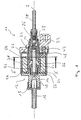
- a dosing pump designed according to the invention is designated generally by 10.
- This metering pump 10 can be used to liquid fuel from a provided in a motor vehicle tank towards a heater such. As a heater or a heater to promote.
- the metering pump 10 comprises a housing assembly 12 which is composed of several components.
- a housing end part 14 is provided on which an inlet pipe 16 to be connected to a hose connection is provided.
- a filter 18 is further provided in the housing end portion 14.
- a housing outer wall 20 is fixedly connected to the housing end part 14, which is connected at its other axial end region - axially relative to a longitudinal axis of the entire metering pump 10 - to a further housing end part 22.
- an elongated, sleeve-like carrier element 24 is supported in the radially inner region-again radially relative to the longitudinal axis A.
- an outlet check valve 26 is supported on this sleeve-like carrier element 24, which comprises a part 28 which essentially provides a valve seat and an outlet connection 30 which can be connected to a hose line.
- a spring-biased valve ball 32 On the valve sits a spring-biased valve ball 32, which prevents that in the outlet nozzle 30 funded liquid fuel flows back again.
- a generally designated 34 solenoid coil is supported on the housing end portion 14 and the support member 24, a generally designated 34 solenoid coil is supported.
- the housing end portion 14, a bobbin 36 of the electromagnetic coil 34 and the support member 24 define a pump inlet chamber 38, to which a In the housing end portion 14 provided inlet opening 40 leads.
- This also designed with a generally ring-like cross-section and subsequently with reference to the 3 and 4 Guide sleeve 42 described in more detail has an interior 44 configured with a circular cross-section, for example.
- This inner space 44 which is bounded by an inner surface 46, bounded in cooperation with the part 28 of the valve assembly 26, a pump discharge chamber 48 and also serves to guide a delivery piston 50 for reciprocation in the direction of the longitudinal axis A.
- engaging region of the delivery piston 50 carries an armature 52.
- a biasing spring 54 of the delivery piston 50 is biased so that it has the tendency to move as far as possible from the interior 44 of the guide sleeve 42 and out with a example on Anchor carried sealing element 56 to complete the inlet opening 40.
- the guide sleeve 42 which according to the principles of the present invention is preferably constructed of plastic material, is of elongate shape and has substantially two lengths.
- the guide sleeve 42 is shaped such that the circumferential contour of an outer surface 60 thereof corresponds to the circumferential contour of an inner surface 62 of the carrier element 24.
- this inner surface 62 is provided with a substantially circular contour, so that in the first longitudinal region 58, the guide sleeve 42 is also formed with a circular outer surface.
- the outer dimension of the guide sleeve 42 at least in this longitudinal region 58 has a certain excess with respect to the inner dimension of the support member 24, so that in particular in this first length portion 58 inserted into the support member 24 Guide sleeve 42 is provided a press fit and thus a stable support of the guide sleeve 42 is present.
- a second length region 64 the shaping of the outer surface of the guide sleeve 42 deviates from the shape of the inner surface 62 of the carrier element 24.
- the guide sleeve 42 is flattened on two mutually opposite circumferential regions, so that substantially planar, ie not curved outer surface regions 70, 72 are formed. These outer surface regions 70, 72 are now at a distance from the inner surface 62 of the carrier element 24, so that a channel arrangement 74 is created between the carrier element 24 and the guide sleeve 42 in this second length region 64 of the guide sleeve 42.
- This channel arrangement 74 adjoins the inlet chamber 38 and leads to passage openings 76, which are respectively provided in the outer surface areas 70, 72 in the adjoining area to the first longitudinal area 58 of the guide sleeve 42 and lead into the inner space 44.
- the position of these openings 76 relative to the longitudinal extension of the guide sleeve 42 is selected such that at maximum drawn out of the guide sleeve 42 delivery piston 50 whose still engaging in the guide sleeve 42 end the openings 76 no longer or no longer completely covers.
- the delivery piston 50 covers the openings 76, so that then a connection between the pump discharge chamber 48 and the channel assembly 74 and thus the pump inlet chamber 38 is interrupted.
- a support portion 78, 80 is provided in each of the flattened surface portions 70, 72.
- the support sections 78, 80 extend from the end region of the guide sleeve 42 near the inlet chamber 38 into the region in which a respective through-opening 76 is formed.
- the projection of the support portions 78, 80 over the respective flattened surface area 70, 72 is selected so that these support portions 78, 80 radially approximately up to the level of the outer surface 60 in the first length portion 58 and in that peripheral region, in which then a respective Abstützabêt 78, 80 connects, rich.
- the delivery piston 50 in the in Fig. 1 As shown, in which the volume of the pump discharge chamber 48 is maximum, and then the solenoid assembly 34 is energized, the armature 52 moves together with the delivery piston 50 in the direction of decreasing the pump discharge chamber volume. After a short delivery stroke, the delivery piston 50 completely covers the openings 76 in the guide sleeve 42, so that no fuel contained in the pump discharge chamber 48 at that time can be forced back through the openings 76 in the direction of the inlet chamber 48.
- the delivery piston 50 returns due to bias again towards increasing the pump discharge chamber volume, in which phase in this pump discharge chamber 48, a negative pressure is generated, as long as the openings 76 still from the delivery piston 50th are covered.
- an overpressure is generated in the inlet chamber 38 by the delivery piston 50 which moves out of the guide sleeve 42. A certain proportion of the liquid fuel can escape through the inlet opening 40.
- the wear in the frictional contact between the delivery piston 50 and the guide sleeve 42 can be significantly reduced.
- the channel assembly 74 ensured that when using plastic material for this guide sleeve 42 nevertheless a very stable support is obtained.
- the shape of the guide sleeve 42 in its second length portion 64 may be different than shown. So a division in a different angle ratio, than 180 ° is possible. Also, it is of course possible to provide the channel assembly 74 with differently shaped groove-like recesses which are open radially outwardly and extend along the guide sleeve 42 to one or more of the apertures 76.
Landscapes
- Engineering & Computer Science (AREA)
- Mechanical Engineering (AREA)
- General Engineering & Computer Science (AREA)
- Details Of Reciprocating Pumps (AREA)
- Fuel-Injection Apparatus (AREA)
- Reciprocating Pumps (AREA)
Claims (9)
- Une pompe doseuse, comprenant:- un piston exerçant un mouvement de va-et-vient pour convoyer un fluide,- une douille de guidage (42) qui reçoit partiellement le piston convoyeur (50) et le guide pendant le movement de va-et-vient, la douille de guidage (42) définissant une chambre d'éjection de pompe (48) par une surface interne (46) et définissant un arrangement de canal (74) menant à la chambre d'éjection de pompe (48) par une surface externe (60), la douille de guidage (42) touchant avec sa surface externe (60) un élément de support (24) sur toute la circonférence dans une première section longitudinale, par cela étant supportée à l'élément de support (24), et la surface externe présentant une distance par rapport à l'élément de support (24) dans une deuxième section longitudinale, l'arrangement de canal (74) étant par cela prévu entre l'élément de support (24) et la douille de guidage (42) dans sa deuxième section longitudinale (64), la douille de guidage (42) présentant au moins une section de support (78, 80, 82, 84) dans sa deuxième section longitudinale (64), par laquelle elle est tenue par rapport à l'élément de support (24),caractérisée par la douille de guidage (42) définissant la chambre d'éjection de pompe (48) dans sa première section longitudinale (58).
- Une pompe doseuse selon la revendication 1,
caractérisée par la douille de guidage (42) présentant dans sa deuxième section longitudinale (64) dans au moins une section circonférentielle une surface externe (70, 72) qui est reculée par rapport à la première section longitudinale (58). - Une pompe doseuse selon la revendication 2,
caractérisée par une section de support (78, 80) étant prévue dans la region de la surface externe reculée (70, 72), qui dépasse cette dernière. - Une pompe doseuse selon la revendication 3,
caractérisée par la section de support (78, 80) dépassant la surface externe reculée (70, 72) jusqu'au niveau de la surface externe dans la première section longitudinale. - Une pompe doseuse selon la revendication 3 ou 4,
caractérisée par au moins un orifice (76) qui mène à la chambre d'éjection de pompe (48) étant prévu dans la region de contact de la première section longitudinale (58) avec la deuxième section longitudinale (64). - Une pompe doseuse selon la revendication 2 à 5,
caractérisée par une surface externe reculée (70, 72) étant prévue à deux sections circonférentielles dans la deuxième section longitudinale (64) qui sont pour l'essentiel opposées. - Une pompe doseuse selon la revendication 1 à 6,
caractérisée par la douille de guidage (42) ayant un contour externe dans sa deuxième section longitudinale (64) qui correspond au contour externe de la douille de guidage (42) dans la première section longitudinale (58) et qui est interrompu à au moins une section circonférentielle par une dépression ouverte vers l'extérieur et prévoyant au moins partiellement l'arrangement de canal (74). - Une pompe doseuse selon une des revendications 1-7,
caractérisée par la douille de guidage (42) étant constituée par une matière plastique. - Une pompe doseuse selon une des revendications 1-8,
caractérisée par la douille de guidage (42) étant constituée par une matière plastique.
Applications Claiming Priority (2)
| Application Number | Priority Date | Filing Date | Title |
|---|---|---|---|
| DE102004002245 | 2004-01-15 | ||
| DE102004002245A DE102004002245A1 (de) | 2004-01-15 | 2004-01-15 | Dosierpumpe |
Publications (3)
| Publication Number | Publication Date |
|---|---|
| EP1555435A2 EP1555435A2 (fr) | 2005-07-20 |
| EP1555435A3 EP1555435A3 (fr) | 2006-01-18 |
| EP1555435B1 true EP1555435B1 (fr) | 2009-04-22 |
Family
ID=34609576
Family Applications (1)
| Application Number | Title | Priority Date | Filing Date |
|---|---|---|---|
| EP05000099A Expired - Lifetime EP1555435B1 (fr) | 2004-01-15 | 2005-01-04 | Pompe de dosage |
Country Status (3)
| Country | Link |
|---|---|
| US (1) | US7621726B2 (fr) |
| EP (1) | EP1555435B1 (fr) |
| DE (2) | DE102004002245A1 (fr) |
Families Citing this family (14)
| Publication number | Priority date | Publication date | Assignee | Title |
|---|---|---|---|---|
| DE102006044254B3 (de) * | 2006-09-16 | 2008-03-27 | Thomas Magnete Gmbh | Membranpumpe |
| DE102006044248B3 (de) * | 2006-09-16 | 2008-04-03 | Thomas Magnete Gmbh | Membranpumpe |
| DE102006044253B3 (de) * | 2006-09-16 | 2008-03-27 | Thomas Magnete Gmbh | Membran und Pumpenkopf für eine hydraulisch angetriebene Membranpumpe |
| DE102006044246B4 (de) * | 2006-09-16 | 2009-05-28 | Thomas Magnete Gmbh | Abgasnachbehandlungssystem |
| DE102006044252B3 (de) * | 2006-09-16 | 2008-02-28 | Thomas Magnete Gmbh | Membranpumpe zur Förderung und Dosierung eines Fluids |
| DE102006044255B3 (de) * | 2006-09-16 | 2008-03-27 | Thomas Magnete Gmbh | Membranpumpe zur Förderung und Dosierung eines Fluids |
| DE102009033736A1 (de) | 2008-07-21 | 2010-01-28 | Thomas Magnete Gmbh | Förder- oder Dosierpumpe, und Verfahren zu deren Betrieb |
| DE102008055609B4 (de) * | 2008-11-03 | 2011-12-29 | Thomas Magnete Gmbh | Hubkolbenpumpe |
| DE102011107761A1 (de) * | 2011-07-15 | 2013-01-17 | Thomas Magnete Gmbh | Dosierpumpe |
| DE102015116783A1 (de) * | 2015-10-02 | 2017-04-06 | Eberspächer Climate Control Systems GmbH & Co. KG | Dosierpumpe, insbesondere Brennstoffdosierpumpe für ein Fahrzeugheizgerät |
| DE102015015845A1 (de) * | 2015-12-05 | 2017-06-08 | Thomas Magnete Gmbh | Hubkolbenpumpe und Verfahren zu ihrem Zusammenbau |
| RU2654808C1 (ru) * | 2017-05-29 | 2018-05-22 | Евсей Аврумович Кордит | Дозировочный насос |
| DE202018106533U1 (de) | 2018-11-19 | 2018-11-28 | Evsey A. Kordit | Dosierpumpe |
| DE102019218092A1 (de) * | 2019-11-22 | 2021-05-27 | Robert Bosch Gmbh | Elektromagnetische Betätigungseinrichtung |
Family Cites Families (6)
| Publication number | Priority date | Publication date | Assignee | Title |
|---|---|---|---|---|
| CH672354A5 (fr) * | 1987-05-19 | 1989-11-15 | Cryopump Ag | |
| DE59600061D1 (de) * | 1995-03-03 | 1998-02-05 | Cryopump Ag | Pumpe zum Pumpen eines verflüssigtes Gas aufweisenden Fluids und Einrichtung mit einer Pumpe |
| US5713723A (en) * | 1996-05-17 | 1998-02-03 | Tuthill Corporation | Volumetric hand pump |
| CZ292533B6 (cs) * | 1999-11-18 | 2003-10-15 | Brano-Ateso A.S., Člen Brano Group | Elektromagnetické pístové čerpadlo |
| DE10111004A1 (de) * | 2001-03-07 | 2002-09-26 | Webasto Thermosysteme Gmbh | Mobiles Heizgerät mit einer Brennstoffzuführeinrichtung |
| CN100371590C (zh) * | 2002-11-01 | 2008-02-27 | 丹福斯有限公司 | 用于将液体燃料输送到家庭燃烧器装置的往复运动液体泵 |
-
2004
- 2004-01-15 DE DE102004002245A patent/DE102004002245A1/de not_active Withdrawn
-
2005
- 2005-01-04 EP EP05000099A patent/EP1555435B1/fr not_active Expired - Lifetime
- 2005-01-04 DE DE502005007117T patent/DE502005007117D1/de not_active Expired - Lifetime
- 2005-01-13 US US11/034,545 patent/US7621726B2/en not_active Expired - Fee Related
Also Published As
| Publication number | Publication date |
|---|---|
| DE502005007117D1 (de) | 2009-06-04 |
| US7621726B2 (en) | 2009-11-24 |
| EP1555435A2 (fr) | 2005-07-20 |
| DE102004002245A1 (de) | 2005-08-11 |
| EP1555435A3 (fr) | 2006-01-18 |
| US20050158192A1 (en) | 2005-07-21 |
Similar Documents
| Publication | Publication Date | Title |
|---|---|---|
| EP1555435B1 (fr) | Pompe de dosage | |
| DE69002473T2 (de) | Hochdruckreiniger mit Bypass. | |
| EP0199143B1 (fr) | Pompe à piston coulissant pour délivrer des substances fluides | |
| EP3938695B1 (fr) | Distributeur de lubrifiant | |
| DE1298882B (de) | Fluessigkeitspumpe, insbesondere Lenzpumpe | |
| EP2094980A2 (fr) | Coquille de coussinet pour machine hydrostatique et machine hydrostatique pourvue de cette coquille de coussinet | |
| EP3080674B1 (fr) | Débitmètre destiné à un système d'extincteur | |
| EP2519743B1 (fr) | Pompe à piston dotée d'une soupape d'admission | |
| EP2483558B1 (fr) | Pompe por une appareil de nettoyage haute pression | |
| EP2483561B1 (fr) | Pompe pour appareil de nettoyage haute pression | |
| DE102009001433A1 (de) | Saugventil für eine Kraftstoffhochdruckpumpe | |
| EP1445485B1 (fr) | Pompe de dosage pour dispositif de chauffage pour véhicule | |
| EP0484773B1 (fr) | Distributeur de fluide | |
| DE29518782U1 (de) | Elektromagnetische Kolbenpumpe | |
| DE112009000777B4 (de) | Handpumpe zum Pumpen von Kraftstoff | |
| EP1857673B1 (fr) | Pompe de dosage, en particulier destinée à l'approvisionnement de carburant pour un appareil de chauffage de véhicule | |
| EP1774176A1 (fr) | Pompe a piston a dynamique de montee en pression amelioree | |
| DE102008046060B4 (de) | Hydraulische Endlagendämpfung einer Hubkolbenpumpe | |
| DE19715709B4 (de) | Flüssigkeitsdispenser, Förder-und Dosierzylinder, Förder-und Dosiervorrichtung und Verfahren zur Herstellung eines Flüssigkeitsdispensers | |
| DE3936357C2 (fr) | ||
| DE10351288B3 (de) | Spenderpumpe | |
| EP4401889A1 (fr) | Dispositif de distribution de portions d'un milieu liquide | |
| DE102009054933A1 (de) | Fluideinlassvorrichtung zum Zuführen von Fluid in eine Kolbenpumpe | |
| DE102015112445A1 (de) | Mischkopf mit einer Schmiereinrichtung für einen Reinigungskolben | |
| DE102012010146B4 (de) | Elektromagnetische Pumpe |
Legal Events
| Date | Code | Title | Description |
|---|---|---|---|
| PUAI | Public reference made under article 153(3) epc to a published international application that has entered the european phase |
Free format text: ORIGINAL CODE: 0009012 |
|
| AK | Designated contracting states |
Kind code of ref document: A2 Designated state(s): AT BE BG CH CY CZ DE DK EE ES FI FR GB GR HU IE IS IT LI LT LU MC NL PL PT RO SE SI SK TR |
|
| AX | Request for extension of the european patent |
Extension state: AL BA HR LV MK YU |
|
| PUAL | Search report despatched |
Free format text: ORIGINAL CODE: 0009013 |
|
| AK | Designated contracting states |
Kind code of ref document: A3 Designated state(s): AT BE BG CH CY CZ DE DK EE ES FI FR GB GR HU IE IS IT LI LT LU MC NL PL PT RO SE SI SK TR |
|
| AX | Request for extension of the european patent |
Extension state: AL BA HR LV MK YU |
|
| RIC1 | Information provided on ipc code assigned before grant |
Ipc: F04B 43/02 20060101AFI20050304BHEP Ipc: F04B 7/04 20060101ALI20051201BHEP Ipc: F04B 53/16 20060101ALI20051201BHEP |
|
| 17P | Request for examination filed |
Effective date: 20060718 |
|
| AKX | Designation fees paid |
Designated state(s): CZ DE SE |
|
| 17Q | First examination report despatched |
Effective date: 20071120 |
|
| GRAP | Despatch of communication of intention to grant a patent |
Free format text: ORIGINAL CODE: EPIDOSNIGR1 |
|
| GRAS | Grant fee paid |
Free format text: ORIGINAL CODE: EPIDOSNIGR3 |
|
| GRAA | (expected) grant |
Free format text: ORIGINAL CODE: 0009210 |
|
| AK | Designated contracting states |
Kind code of ref document: B1 Designated state(s): CZ DE SE |
|
| REF | Corresponds to: |
Ref document number: 502005007117 Country of ref document: DE Date of ref document: 20090604 Kind code of ref document: P |
|
| REG | Reference to a national code |
Ref country code: SE Ref legal event code: TRGR |
|
| PLBE | No opposition filed within time limit |
Free format text: ORIGINAL CODE: 0009261 |
|
| STAA | Information on the status of an ep patent application or granted ep patent |
Free format text: STATUS: NO OPPOSITION FILED WITHIN TIME LIMIT |
|
| 26N | No opposition filed |
Effective date: 20100125 |
|
| EUG | Se: european patent has lapsed | ||
| PGFP | Annual fee paid to national office [announced via postgrant information from national office to epo] |
Ref country code: CZ Payment date: 20101231 Year of fee payment: 7 |
|
| PG25 | Lapsed in a contracting state [announced via postgrant information from national office to epo] |
Ref country code: CZ Free format text: LAPSE BECAUSE OF NON-PAYMENT OF DUE FEES Effective date: 20120104 |
|
| PG25 | Lapsed in a contracting state [announced via postgrant information from national office to epo] |
Ref country code: SE Free format text: LAPSE BECAUSE OF NON-PAYMENT OF DUE FEES Effective date: 20100105 |
|
| REG | Reference to a national code |
Ref country code: DE Ref legal event code: R082 Ref document number: 502005007117 Country of ref document: DE Representative=s name: WEICKMANN & WEICKMANN, DE |
|
| REG | Reference to a national code |
Ref country code: DE Ref legal event code: R081 Ref document number: 502005007117 Country of ref document: DE Owner name: EBERSPAECHER CLIMATE CONTROL SYSTEMS GMBH & CO, DE Free format text: FORMER OWNER: J. EBERSPAECHER GMBH & CO. KG, 73730 ESSLINGEN, DE Effective date: 20130607 Ref country code: DE Ref legal event code: R082 Ref document number: 502005007117 Country of ref document: DE Representative=s name: WEICKMANN & WEICKMANN, DE Effective date: 20130607 Ref country code: DE Ref legal event code: R082 Ref document number: 502005007117 Country of ref document: DE Representative=s name: RUTTENSPERGER LACHNIT TROSSIN GOMOLL PATENT- U, DE Effective date: 20130607 Ref country code: DE Ref legal event code: R082 Ref document number: 502005007117 Country of ref document: DE Representative=s name: RUTTENSPERGER LACHNIT TROSSIN GOMOLL, PATENT- , DE Effective date: 20130607 |
|
| REG | Reference to a national code |
Ref country code: DE Ref legal event code: R082 Ref document number: 502005007117 Country of ref document: DE Representative=s name: RUTTENSPERGER LACHNIT TROSSIN GOMOLL PATENT- U, DE Ref country code: DE Ref legal event code: R082 Ref document number: 502005007117 Country of ref document: DE Representative=s name: RUTTENSPERGER LACHNIT TROSSIN GOMOLL, PATENT- , DE |
|
| PGFP | Annual fee paid to national office [announced via postgrant information from national office to epo] |
Ref country code: DE Payment date: 20170131 Year of fee payment: 13 |
|
| REG | Reference to a national code |
Ref country code: DE Ref legal event code: R119 Ref document number: 502005007117 Country of ref document: DE |
|
| PG25 | Lapsed in a contracting state [announced via postgrant information from national office to epo] |
Ref country code: DE Free format text: LAPSE BECAUSE OF NON-PAYMENT OF DUE FEES Effective date: 20180801 |