EP1555419A1 - Prozess und Vorrichtung zur Optimierung der Strömungssteuerung einer Flüssigkeit durch Anpassung des Druckverlust - Google Patents
Prozess und Vorrichtung zur Optimierung der Strömungssteuerung einer Flüssigkeit durch Anpassung des Druckverlust Download PDFInfo
- Publication number
- EP1555419A1 EP1555419A1 EP03447307A EP03447307A EP1555419A1 EP 1555419 A1 EP1555419 A1 EP 1555419A1 EP 03447307 A EP03447307 A EP 03447307A EP 03447307 A EP03447307 A EP 03447307A EP 1555419 A1 EP1555419 A1 EP 1555419A1
- Authority
- EP
- European Patent Office
- Prior art keywords
- section
- pressure drop
- regulation
- hydraulic
- distance
- Prior art date
- Legal status (The legal status is an assumption and is not a legal conclusion. Google has not performed a legal analysis and makes no representation as to the accuracy of the status listed.)
- Withdrawn
Links
Images

Classifications
-
- F—MECHANICAL ENGINEERING; LIGHTING; HEATING; WEAPONS; BLASTING
- F02—COMBUSTION ENGINES; HOT-GAS OR COMBUSTION-PRODUCT ENGINE PLANTS
- F02K—JET-PROPULSION PLANTS
- F02K9/00—Rocket-engine plants, i.e. plants carrying both fuel and oxidant therefor; Control thereof
- F02K9/42—Rocket-engine plants, i.e. plants carrying both fuel and oxidant therefor; Control thereof using liquid or gaseous propellants
- F02K9/44—Feeding propellants
- F02K9/56—Control
- F02K9/58—Propellant feed valves
Definitions
- the present invention relates to a optimized control method according to the need of the flow of a fluid (flow or pressure) via its loss load in a system of rotating grids.
- the invention also relates to mobile grid device specially adapted for placing implementation of the method.
- a device for regulating the loss of charge by means of a system of rotating grids is known and used on rocket engines.
- Figure 1 illustrates an example of a need to regulation which corresponds to a limited range of positions angle of regulation equipment.
- the characteristic acting on the regulation is, in this example, the pressure drop of the flow, reduced to a coefficient of loss of load.
- the need for system to be regulated is reflected in a variation of this coefficient between two extreme values C1 and C2.
- the present invention aims to provide a solution that makes it possible to overcome the disadvantages of the state of the art.
- the invention aims to adapt to different laws of variation of loss of load according to need, whatever the type actuator used.
- a first aspect of the present invention is relates to a method of regulating the flow of a fluid, in particular the flow or pressure of the fluid, by adjusting its pressure drop in a hydraulic or pneumatic device, characterized in that means are used which, once the need in regulation set, to define the range of regulation satisfying this need, preferably the center and the width of that beach, depending on regulation parameter, said means making the essentially independent control of the actuator used for adjusting the pressure drop.
- the need for regulation is the accuracy of the pressure loss or the stability of the point Operating.
- said means comprise a gate shutter disposed in the flow path fluid, having a fixed grid and a movable grid rotating, separated by a certain distance, so-called distance inter-grids, the assembly defining a section hydraulic front passage and a hydraulic section cross passage between the two grids.
- the distance between grids is chosen so that the frontal section is significantly larger than the cross section over the defined regulation range, the pressure loss being essentially influenced by the angular position of the movable grid.
- the distance between grids is chosen so that the frontal section is of the same order of magnitude as the cross section over the defined control range.
- the distance between grids is chosen so that the frontal section is significantly smaller than the cross section over the defined regulation range, the pressure drop being mainly influenced by the inter-grid distance.
- the regulation parameter is the front passage surface, said passage surface front end being correlated with the angular position of the mobile grid.
- the passage surface frontal varies linearly with said angular position.
- a second aspect of the present invention relates to a device for regulating pressure drop of a hydraulic or pneumatic element for the implementation of the process described above, preferably comprising a gate shutter disposed in the flow path fluid, having a fixed grid and a movable grid rotating, separated by a certain adjustable distance, said inter-grid distance, the assembly defining a hydraulic section of frontal passage and a section hydraulic cross passage between the two grids.
- This device and the regulation method put in particular are intended for the regulation of a hydraulic or pneumatic system in a rocket engine.
- Figure 1 already mentioned, represents schematically an example of need in regulation: loss charge with high accuracy required in a range determined angle.
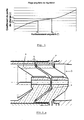
- Figure 2.a shows a sectional view in an axial plane of an example of a grid device rotating, as used in the context of this invention
- Figure 2.b schematically represents a cross-sectional view of the device of figure 2.a
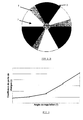
- Figure 3 shows schematically the influence of the angular position on the loss of charge, using the device of Figure 2.
- Figure 4 shows schematically the influence of the frontal surface of the passage of the fluid on pressure drop, using the device of Figure 2.
- the invention consists in allowing the regulation via optimized pressure loss according to the need for any regulated hydraulic assembly.
- the example shown in Figures 2.a and 2.b includes a system of two grids: a fixed grid 1 and a movable grid 2.
- the original method described below is intended to optimize the gradual variation range of the desired characteristic of the control equipment against the need for regulation imposed by the system.
- optimization is achieved via the determination of the Ideal geometry of the shutter of the equipment.
- This regulation via the pressure drop is made according to the angular positioning of the grid mobile.
- Figure 3 shows an example of a test done with the grid system rotative shown in Figure 2.
- zone I the pressure loss varies mainly according to the frontal surface of passage for fixed flow values (pressure, flow rate, speed, etc.).
- the present invention has the advantage the fact that the need for regulation can be satisfied by modifying the geometry of the gate of the shutter and that of quasi-independent way of the actuator used. So, for example, using a proper grid drawing, one can obtain a better precision of pressure loss, for a given actuator. This implies the possibility of simplification of the operation of the equipment, with a cost reduction.
- the invention also makes it possible to target areas of work, depending on the need encountered, such as for example to increase the accuracy of the pressure drop at a particular place.
- This system also allows the use of the same equipment where only the drawing of the cross section of the grids can be changed to to achieve another functionality.
Landscapes
- Engineering & Computer Science (AREA)
- Chemical & Material Sciences (AREA)
- Combustion & Propulsion (AREA)
- Mechanical Engineering (AREA)
- General Engineering & Computer Science (AREA)
- Fluid-Pressure Circuits (AREA)
- Flow Control (AREA)
- Aerodynamic Tests, Hydrodynamic Tests, Wind Tunnels, And Water Tanks (AREA)
Priority Applications (4)
| Application Number | Priority Date | Filing Date | Title |
|---|---|---|---|
| EP03447307A EP1555419A1 (de) | 2003-12-23 | 2003-12-23 | Prozess und Vorrichtung zur Optimierung der Strömungssteuerung einer Flüssigkeit durch Anpassung des Druckverlust |
| AT04029376T ATE364784T1 (de) | 2003-12-23 | 2004-12-10 | Prozess und vorrichtung zur optimierung der strömungssteuerung einer flüssigkeit durch anpassung des drukverlust |
| EP04029376A EP1555420B1 (de) | 2003-12-23 | 2004-12-10 | Prozess und Vorrichtung zur Optimierung der Strömungssteuerung einer Flüssigkeit durch Anpassung des Drukverlust |
| DE602004006950T DE602004006950T2 (de) | 2003-12-23 | 2004-12-10 | Prozess und Vorrichtung zur Optimierung der Strömungssteuerung einer Flüssigkeit durch Anpassung des Drukverlust |
Applications Claiming Priority (1)
| Application Number | Priority Date | Filing Date | Title |
|---|---|---|---|
| EP03447307A EP1555419A1 (de) | 2003-12-23 | 2003-12-23 | Prozess und Vorrichtung zur Optimierung der Strömungssteuerung einer Flüssigkeit durch Anpassung des Druckverlust |
Publications (1)
| Publication Number | Publication Date |
|---|---|
| EP1555419A1 true EP1555419A1 (de) | 2005-07-20 |
Family
ID=34610152
Family Applications (1)
| Application Number | Title | Priority Date | Filing Date |
|---|---|---|---|
| EP03447307A Withdrawn EP1555419A1 (de) | 2003-12-23 | 2003-12-23 | Prozess und Vorrichtung zur Optimierung der Strömungssteuerung einer Flüssigkeit durch Anpassung des Druckverlust |
Country Status (3)
| Country | Link |
|---|---|
| EP (1) | EP1555419A1 (de) |
| AT (1) | ATE364784T1 (de) |
| DE (1) | DE602004006950T2 (de) |
Cited By (2)
| Publication number | Priority date | Publication date | Assignee | Title |
|---|---|---|---|---|
| CN103953462A (zh) * | 2014-05-06 | 2014-07-30 | 中国航天科技集团公司第六研究院第十一研究所 | 一种可调汽蚀管 |
| CN119412247A (zh) * | 2024-11-22 | 2025-02-11 | 北京星河动力装备科技有限公司 | 调节阀、发动机及火箭 |
Citations (5)
| Publication number | Priority date | Publication date | Assignee | Title |
|---|---|---|---|---|
| US3759091A (en) * | 1971-07-02 | 1973-09-18 | Gen Electric | Engine inlet distortion testing apparatus |
| US4328831A (en) * | 1973-11-01 | 1982-05-11 | Wolff Robert C | Rotary valve |
| US5409351A (en) * | 1992-05-04 | 1995-04-25 | Abb Patent Gmbh | Steam turbine with a rotary slide |
| DE4425345A1 (de) * | 1994-07-18 | 1996-01-25 | Abb Patent Gmbh | Anordnung mit mindestens einem Axialnadeldrehkranz als drehbewegliches Lagerelement in einem Drehschieber |
| EP1108929A1 (de) * | 1999-12-16 | 2001-06-20 | Techspace Aero S.A. | Vorrichtung zum Regeln des Durchflusses eines Fluids |
-
2003
- 2003-12-23 EP EP03447307A patent/EP1555419A1/de not_active Withdrawn
-
2004
- 2004-12-10 AT AT04029376T patent/ATE364784T1/de not_active IP Right Cessation
- 2004-12-10 DE DE602004006950T patent/DE602004006950T2/de not_active Expired - Fee Related
Patent Citations (5)
| Publication number | Priority date | Publication date | Assignee | Title |
|---|---|---|---|---|
| US3759091A (en) * | 1971-07-02 | 1973-09-18 | Gen Electric | Engine inlet distortion testing apparatus |
| US4328831A (en) * | 1973-11-01 | 1982-05-11 | Wolff Robert C | Rotary valve |
| US5409351A (en) * | 1992-05-04 | 1995-04-25 | Abb Patent Gmbh | Steam turbine with a rotary slide |
| DE4425345A1 (de) * | 1994-07-18 | 1996-01-25 | Abb Patent Gmbh | Anordnung mit mindestens einem Axialnadeldrehkranz als drehbewegliches Lagerelement in einem Drehschieber |
| EP1108929A1 (de) * | 1999-12-16 | 2001-06-20 | Techspace Aero S.A. | Vorrichtung zum Regeln des Durchflusses eines Fluids |
Cited By (3)
| Publication number | Priority date | Publication date | Assignee | Title |
|---|---|---|---|---|
| CN103953462A (zh) * | 2014-05-06 | 2014-07-30 | 中国航天科技集团公司第六研究院第十一研究所 | 一种可调汽蚀管 |
| CN119412247A (zh) * | 2024-11-22 | 2025-02-11 | 北京星河动力装备科技有限公司 | 调节阀、发动机及火箭 |
| CN119412247B (zh) * | 2024-11-22 | 2026-01-13 | 北京星河动力装备科技有限公司 | 调节阀、发动机及火箭 |
Also Published As
| Publication number | Publication date |
|---|---|
| DE602004006950D1 (de) | 2007-07-26 |
| ATE364784T1 (de) | 2007-07-15 |
| DE602004006950T2 (de) | 2008-02-28 |
Similar Documents
| Publication | Publication Date | Title |
|---|---|---|
| EP3377742B1 (de) | Stange für einen motor mit variablem verdichtungsverhältnis | |
| WO2014167190A1 (fr) | Dispositif de commande de l'alimentation d'un systeme avec un fluide permettant une optimisation de la consommation de fluide | |
| FR3043720B1 (fr) | Moteur a rapport volumetrique variable | |
| EP3055596B1 (de) | Verfahren zum entwurf eines ventils und verfahren zur herstellung eines ventils | |
| EP1555419A1 (de) | Prozess und Vorrichtung zur Optimierung der Strömungssteuerung einer Flüssigkeit durch Anpassung des Druckverlust | |
| EP1266149A1 (de) | Hydraulischer dämpfer mit regelbarer dämpfungskennlinie | |
| EP2385411B1 (de) | Korrekturverfahren von Aberrationen innerhalb einer optischen Vorrichtung, die ein Gebiet durch ein Fenster beobachtet | |
| EP1555420B1 (de) | Prozess und Vorrichtung zur Optimierung der Strömungssteuerung einer Flüssigkeit durch Anpassung des Drukverlust | |
| WO2017085408A1 (fr) | Bielle pour moteur a rapport volumetrique variable | |
| EP2598929B1 (de) | Passives mechanisches athermalisationsvorrichtung und zugehöriges optisches system | |
| EP1818711B1 (de) | Bimorpher Spiegel mit zwei piezoelektrischen Schichten | |
| EP3775577B1 (de) | Flüssigkeitsventil | |
| FR2805872A1 (fr) | Clapet de laminage a raideur reglable et amortisseur associe | |
| WO2024074661A1 (fr) | Système de projection de fluide de nettoyage avec deux buses de projection et une valve directionnelle | |
| FR3000770A1 (fr) | Machine hydraulique a deux sens de rotation, comportant une chambre de pre-compression | |
| FR3030649A1 (fr) | Mecanisme d'entrainement d'organes de reglage de l'orientation des pales | |
| FR2508566A1 (fr) | Distributeur de commande de verin | |
| FR3057327A1 (fr) | Mecanisme d'entrainement d'organes de reglage de l'orientation des pales | |
| FR3031361A1 (fr) | Moteur a combustion interne a cylindree variable | |
| WO2012045956A1 (fr) | Dispositif pour transmettre des efforts de traction entre au moins deux cables | |
| WO2015086938A1 (fr) | Dispositif de regulation de la rotation d'un arbre, notamment dans le domaine automobile | |
| FR3081525A1 (fr) | Vilebrequin pour un moteur a rapport volumetrique variable pilote | |
| WO2003000534A2 (fr) | Procede et dispositif de repartition d'un flux d'entree entre un flux de sortie prioritaire et un flux de sortie secondaire | |
| FR3085431A1 (fr) | Moteur a rapport volumetrique pilote | |
| FR2891319A1 (fr) | Injecteur pour optimisation de nappe de carburant. |
Legal Events
| Date | Code | Title | Description |
|---|---|---|---|
| PUAI | Public reference made under article 153(3) epc to a published international application that has entered the european phase |
Free format text: ORIGINAL CODE: 0009012 |
|
| AK | Designated contracting states |
Kind code of ref document: A1 Designated state(s): AT BE BG CH CY CZ DE DK EE ES FI FR GB GR HU IE IT LI LU MC NL PT RO SE SI SK TR |
|
| AX | Request for extension of the european patent |
Extension state: AL LT LV MK |
|
| AKX | Designation fees paid | ||
| REG | Reference to a national code |
Ref country code: DE Ref legal event code: 8566 |
|
| STAA | Information on the status of an ep patent application or granted ep patent |
Free format text: STATUS: THE APPLICATION IS DEEMED TO BE WITHDRAWN |
|
| 18D | Application deemed to be withdrawn |
Effective date: 20060121 |