EP1555352A2 - Water vessel with an integrated storage compartment - Google Patents
Water vessel with an integrated storage compartment Download PDFInfo
- Publication number
- EP1555352A2 EP1555352A2 EP04030854A EP04030854A EP1555352A2 EP 1555352 A2 EP1555352 A2 EP 1555352A2 EP 04030854 A EP04030854 A EP 04030854A EP 04030854 A EP04030854 A EP 04030854A EP 1555352 A2 EP1555352 A2 EP 1555352A2
- Authority
- EP
- European Patent Office
- Prior art keywords
- shell
- water vessel
- storage compartment
- closure member
- receptacle
- Prior art date
- Legal status (The legal status is an assumption and is not a legal conclusion. Google has not performed a legal analysis and makes no representation as to the accuracy of the status listed.)
- Withdrawn
Links
Images

Classifications
-
- A—HUMAN NECESSITIES
- A47—FURNITURE; DOMESTIC ARTICLES OR APPLIANCES; COFFEE MILLS; SPICE MILLS; SUCTION CLEANERS IN GENERAL
- A47K—SANITARY EQUIPMENT; ACCESSORIES THEREFOR, e.g. TOILET ACCESSORIES
- A47K3/00—Baths; Showers; Appurtenances therefor
- A47K3/001—Accessories for baths, not provided for in other subgroups of group A47K3/00; Insertions, e.g. for babies; Tubs suspended or inserted in baths; Security or alarm devices; Protecting linings or coverings; Devices for cleaning or disinfecting baths; Bath insulation
-
- A—HUMAN NECESSITIES
- A47—FURNITURE; DOMESTIC ARTICLES OR APPLIANCES; COFFEE MILLS; SPICE MILLS; SUCTION CLEANERS IN GENERAL
- A47K—SANITARY EQUIPMENT; ACCESSORIES THEREFOR, e.g. TOILET ACCESSORIES
- A47K3/00—Baths; Showers; Appurtenances therefor
- A47K3/28—Showers or bathing douches
- A47K3/281—Accessories for showers or bathing douches, e.g. cleaning devices for walls or floors of showers
-
- E—FIXED CONSTRUCTIONS
- E03—WATER SUPPLY; SEWERAGE
- E03C—DOMESTIC PLUMBING INSTALLATIONS FOR FRESH WATER OR WASTE WATER; SINKS
- E03C1/00—Domestic plumbing installations for fresh water or waste water; Sinks
- E03C1/12—Plumbing installations for waste water; Basins or fountains connected thereto; Sinks
- E03C1/18—Sinks, whether or not connected to the waste-pipe
Definitions
- the invention relates to improvements for water vessels such as sinks, showers, bathtubs, tub showers, and spas, etc. More specifically, it relates to a water vessel including at least one storage compartment therein to store various items, such as kitchen brushes, rubber gloves, soaps, nail cutters, razors, scourers, sponges, scrub brushes, and the like.
- Water vessels such as sinks, showers, bathtubs, tub showers, and spas, are usually devoid of storage space which could be useful for storing small and medium-size items.
- kitchen sinks provided with one or more storage spaces would be of interest, especially for storing kitchen and scrubbing tools that are still humid after use.
- These tools are usually stored in a plastic or a wood container on a shelf close to the sink where water contained in the tool slowly evaporates. If the container is located in a closed space such as a drawer or a cabinet, undesirable odors can be generated due to bacterial formation or merely evaporation.
- Sponges, scrubbers, and other moist cleaning items harbor bacteria and promote bacterial growth since they provide warm, moist breeding ground for bacteria.
- storage space is desirable in showers, bathtubs and tub showers to store various items such as sponges, shampoo, nail cutters, razors, soaps, etc.
- One aspect of the invention provides a water vessel comprising: a shell; a closable storage compartment integrated to the shell; and a closure member displaceable between an open position to provide access to the storage compartment and a closed position to substantially prevent liquid contained in the shell to leak into the storage compartment.
- a second aspect of the invention provides a closable storage compartment in combination with a water vessel having a shell, the storage compartment being integrated to the shell and having an opening accessible from within the shell, and a closure member for selectively closing the opening.
- Another aspect of the invention provides a method of integrating storage space to a water vessel.
- the method comprises: providing a water vessel having a shell; providing a storage compartment in an inner surface of the shell; and providing a closure member for selectively closing the storage compartment.
- a water vessel comprising: a shell; a closable storage compartment recessed in an inner surface of the shell; and a closure member displaceable between an open position to provide access to the storage compartment and a closed position to substantially prevent liquid contained in the shell to leak into the storage compartment.
- the water vessel also includes at least one guide for guiding the movement of the closure member between the open and the closed positions.
- the water vessel also includes at least one seal provided between the closure member and the water vessel shell when the closure member is closed against an inner face of the water vessel shell.
- a water vessel comprising: a shell; a closable storage compartment integrated to the shell; a closure member displaceable between an open position to provide access to the storage compartment and a closed position to substantially prevent liquid contained in the shell to leak into the storage compartment; and at least one seal provided between the closure member and the water vessel shell when the closure member is closed against an inner face of the water vessel shell.
- the water vessel also includes at least one guide for guiding the movement of the closure member between the open and the closed positions.
- the storage compartment is recessed in an inner surface of the shell.
- a water vessel comprising: a shell; a closable storage compartment integrated to the shell; and a closure member displaceable between an open position to provide access to the storage compartment and a closed position to substantially prevent liquid contained in the shell to leak into the storage compartment.
- the storage compartment includes a cell member and a receptacle operably disposed in the cell member.
- the storage compartment is recessed in an inner surface of the shell.
- the water vessel also includes at least one guide for guiding the movement of the closure member between the open and the closed positions.
- the water vessel also includes at least one seal provided between the closure member and the water vessel shell when the closure member is closed against an inner face of the water vessel shell.
- a further aspect of the invention provides a water vessel comprising: a shell; a closable storage compartment integrated to the shell; a closure member displaceable between an open position to provide access to the storage compartment and a closed position to substantially prevent liquid contained in the shell to leak into the storage compartment; and a drain adapted to evacuate the residual water contained in the water vessel.
- the storage compartment is recessed in an inner surface of the shell.
- the water vessel also includes at least one guide for guiding the movement of the closure member between the open and the closed positions.
- the storage compartment includes a cell member and a receptacle operably disposed in the cell member.
- Another aspect of the invention provides a closable storage compartment in combination with a water vessel having a shell, the storage compartment being recessed in an inner surface of the shell and having an opening accessible from within the shell, and a closure member for selectively closing the opening.
- the storage compartment includes a cell member and a receptacle operably disposed in the cell member.
- Another aspect of the invention provides a closable storage compartment in combination with a water vessel having a shell, the storage compartment being integrated to the shell and having an opening accessible from within the shell, and a closure member for selectively closing the opening.
- the storage compartment also includes a cell member and a receptacle operably disposed in the cell member.
- the water vessel also includes at least one guide associated with the cell member and the receptacle to guide the movement of the receptacle within the cell member.
- Another aspect of the invention provides a closable storage compartment in combination with a water vessel having a shell, the storage compartment being integrated to the shell and having an opening accessible from within the shell, a closure member for selectively closing the opening, and a drain adapted to evacuate the residual water contained in the water vessel.
- the storage compartment is recessed in an inner surface of the shell.
- the storage compartment includes a cell member and a receptacle operably disposed in the cell member.
- Another aspect of the invention provides a method of integrating storage space to a water vessel.
- the method comprises: providing a water vessel having a shell; providing a storage compartment in an inner surface of the shell; providing a closure member for selectively closing the storage compartment; and providing at least one guide for the closure member for guiding its movement between an open and a closed position.
- it also includes providing at least one seal for preventing the liquid contained in the shell to leak into the storage compartment.
- Another aspect of the invention provides a method of integrating storage space to a water vessel.
- the method comprises: providing a water vessel having a shell; providing a storage compartment in an inner surface of the shell; providing a closure member for selectively closing the storage compartment; and providing at least one seal for preventing the liquid contained in the shell to leak into the storage compartment.
- it also includes providing at least one guide for the closure member for guiding its movement between an open and a closed position.
- Another aspect of the invention provides a method of integrating storage space to a water vessel.
- the method comprises: providing a water vessel having a shell; providing a storage compartment in an inner surface of the shell; providing a closure member for selectively closing the storage compartment; and adapting the storage compartment to evacuate the residual water contained therein.
- it also includes providing at least one seal for preventing the liquid contained in the shell to leak into the storage compartment.
- it also includes providing at least one guide for the closure member for guiding its movement between an open and a closed position.
- Another aspect of the invention provides a method of integrating storage space to a water vessel.
- the method comprises: providing a water vessel having a shell; providing a storage compartment in an inner surface of the shell; providing a closure member for selectively closing the storage compartment; providing at least one guide for the closure member for guiding its movement between an open and a closed position; and adapting the storage compartment to evacuate the residual water contained therein.
- it also includes providing at least one seal for preventing the liquid contained in the shell to leak into the storage compartment.
- water vessel is intended to mean any container that can contain water for domestic uses such as a sink, a shower, a bathtub, a tub shower, and a spa.
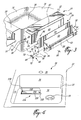
- the water vessel shown in Fig. 1 is a standard sink basin 10 having a shell 12 with four side walls 14 extending upwardly from the perimeter of a bottom surface 16 in which a drain 18 is provided.
- the sink basin 10 can include a top flange 20 and, possibly, a front facade and a backsplash member (not shown).
- the sink basin 10 can be mounted to a kitchen island (not shown), a cabinet (not shown), a counter top, on a wall, or the like.
- the sink basin 10 can be any shape such as circular or oval.
- two accessory storage containers 24 are mounted in two openings 26 formed in the side walls 14 of the sink basin 10.
- the accessory containers 24 can be mounted to any side walls 14 of the sink basin 10 as shown or, alternatively, it can be incorporated in the bottom surface 16 (FIG. 4).
- the accessory containers 24 can be provided in the form of a tilt-out drawer or a sliding drawer, or the like.
- each container 24 includes a cell 30 and a receptacle 32 that will be described more in detail later.
- the cell 30 has a bottom wall 36, two lateral side walls 38, a back wall 40, and an upper wall 42.
- the bottom wall 36 is slightly inclined towards the sink basin 10 to allow residual water to flow into the sink basin 10 and, eventually, to escape through the drain 18.
- the cell 30 can also be directly connected (not shown) to the drain 18 as it will readily be understood by one skilled in the art.
- a receptacle 32 is pivotally mounted in each cell 30 by means of hinges 46 (FIG. 3).
- hinges 46 FIG. 3
- the receptacle 32 has a front wall 50, and a back wall 52, two lateral side walls 54, and a bottom wall 56.
- the bottom wall 56 as illustrated, is in the form of a screen and it is designed to allow residual water to flow outside the receptacle 32 and aerate the latter to reduce bacterial growth.
- the receptacle 32 pivots between an open position and a closed position inside the cell 30.
- the front wall 50 In the closed position, the front wall 50 is designed to cover the opening 26, in juxtaposed position with respect to the side wall 14 of the sink basin 10, and prevents water infiltration inside the cell 30 and the receptacle 32.
- the front wall 50 also acts as a closure member 60.
- a closure member 60 can be mounted to the front wall 50 of the receptacle 32 by any technique known to one skilled in the art.
- the front wall 50 and the closure member 60 can be the same member.
- the hinge 46 includes a pin 62 having a first portion 64 and a second portion 66.
- the first portion 64 has a larger diameter than the second portion 66 and includes an aperture 68 therein.
- the pin 62 is inserted into an opening 70 in the lateral side wall 38 of the cell 30.
- the diameter of the opening 70 is larger than the diameter of the second portion 66 but smaller than the diameter of the first portion 64. Therefore, the first portion 64 abuts the lateral side wall 38.
- the pin 62 is fastened to the cell 30 by means of fasteners 72 such as screws, bolts, and any other fastening means known to one skilled in the art.
- the second portion 66 of the pin 62 is inserted into a groove 74 defined in the lateral side walls 54 of the receptacle 32 and pivots therein.
- the second portion 66 of the pin 62 can be covered with a cap 76 made of a rubber material that is slightly compressed when the second portion 66 is inserted into the groove 74.
- the hinge 46 is not restricted to the construction illustrated in FIG. 3 and may include any pivoting means known to one skilled in the art for tilt-out drawers.
- it can be pins (not shown) mounted in the lateral side walls 54 of the receptacle 32, or alternately in the lateral side walls 38 of the cell 30, so as to allow the rotation of the receptacle 32 therearound.
- spring loaded pins can be used.
- the container 24 also includes an abutment member to smooth and stop the closing operation.
- an abutment member to smooth and stop the closing operation.
- three abutment members 78, 80 are mounted to the cell 30.
- the first two abutment members 78 are mounted to the lateral side walls 38 of the cell 30 (only one is shown).
- the abutment members 78 is preferably made of a rubber material and inserted in an opening 84 in the lateral side walls 38 and fastened to the cell 30 by means of fasteners 72 such as screws, bolts, and any other fastening means known to one skilled in the art.
- fasteners 72 such as screws, bolts, and any other fastening means known to one skilled in the art.
- a second abutment member 80 preferably made of a rubber material, is mounted into a hole 86 located in the back wall 40 of the cell 30. Again upon reaching its closed position, the receptacle back wall 52 abuts the abutment member 80 and stops smoothly the pivoting movement of the receptacle 32.
- the abutment member 80 can be mounted to any part of the receptacle 32 that abuts another part of the cell 30 or the shell 12 of the sink basin 10 while pivoting the receptacle 32. Of course, the abutment member 80 can be disposed anywhere provided the pivoting movement is stopped and smoothness is achieved when closing the receptacle 32 inside the cell 30.
- the abutment member 80 is preferably shock absorbent, for example it can be made of a rubber material.
- a seal (not shown) can be disposed on the side wall 14, along the perimeter of the opening 26, in a manner such that the front wall 50 of the receptacle 32 abuts the seal in the closed position of the receptacle 32.
- the seal should prevent water infiltration inside the cell 30 and/or the receptacle 32.
- the seal can also be disposed along the periphery of the inner surface 88 of the front wall 50 in a manner such that the seal abuts the inner face of the sink basin 10 in the closed position of the receptacle 32.
- the container 24 can include a sliding drawer (not shown) instead of a tilt-out drawer as shown in the above-mentioned figures.
- the container 24 instead of a hinge or a pin, the container 24 includes a rail (not shown).
- the pin, the hinge, and the rail act as guides for the movement of the receptacle 32 between an open and a closed positions.
- the container 24 includes a cell 30.
- the container 24 can only include a receptacle 32 that communicates with the drain 18 to eliminate residual water therefrom.
- the lateral vertical side walls can extend outwardly from the opening 26 and the hinge(s) for a tilt-out drawer or the rail(s) for a sliding drawer are mounted thereon.
- the container 24 includes a lower surface that extends outwardly from the opening 26 and the hinge(s) for the tilt-out drawer or the rail(s) for sliding drawers are mounted thereon.
- the container 24 can include only a cell 30 and a closure member 60, such as closure plate or a front wall, that pivots or slides between an open and a closed positions.
- a closure member 60 such as closure plate or a front wall, that pivots or slides between an open and a closed positions.
- the cell 30 itself constitutes the receptacle 32.
- FIG. 4 there is shown a sink basin 10 similar to the one of FIGS. 1-3 wherein the container 124 is positioned on bottom surface 16 of sink basin 10.
- the container 124 includes a receptacle 132, which has four lateral side walls 154 and a bottom surface 156, and a closure member 160.
- the bottom surface 156 communicates directly or indirectly with the drain 18 to eliminate the residual water therein.
- the closure member 160 is removably disposed over the receptacle 132 to cover the opening 126 formed in sink basin 10.
- the closure member 160 can pivot or slide between an open and a closed positions of the receptacle 132. It can also simply be removed from the receptacle 132 when the user wants to have an access thereto.
- the container 124 also includes a seal (not shown) between the closure member 160 and the sink basin 10 to prevent water infiltration in the receptacle 132.
- a similar container 124 including only a fixed receptacle 132 and a closure member 160 can also be mounted to the side walls 14 of sink basin 10.
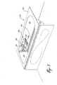
- FIG. 5 there is shown a standard bathtub 210 having a shell 212 with four side walls 214, a bottom surface 216, and a drain (not shown).
- the bathtub 210 can have any shape.
- An accessory container 224 is mounted in an opening 226 formed in a side wall 214 of the shell 212.
- the accessory container 224 can be mounted in any side walls 214 of the bathtub 210 as shown or in the bottom surface 216 (not shown).
- the accessory container 224 can include either a tilt-out drawer or a sliding drawer, or the like.
- the container 224 has a cell (not shown) similar to the one described above for the sink basin.
- the cell includes a receptacle 232 with a front wall 258, a back wall (not shown), four lateral side walls 254, and a bottom wall 256.
- the receptacle 232 is slidingly mounted in the cell by means of rails 258.
- the receptacle 232 is similar to the one describe hereinabove.
- more than one receptacle 232 can be mounted in each cell.
- the receptacle 232 slides between an open and a closed position inside the cell.
- the front wall 250 is designed to cover the opening 226, in juxtaposed position with respect to the side wall 214 of the bathtub 210, and should also prevent water infiltration inside the cell and the receptacle 232.
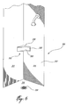
- FIG. 6 there is shown a standard shower 310 having a shell 312 with side walls 314, a bottom surface 316, and a drain 318.
- the shower 310 can have any shape or can be made of any material.
- An accessory container 324 is mounted to the side walls 314 of the shower 310.
- the accessory container 324 can be mounted to or in any side walls 314 of the shower 310 as shown or in the bottom surface 316 (not shown).
- the container 324 has a cell 330 similar to the one described above for the sink basin 10 and the bathtub 210.
- the cell 330 includes a receptacle 332 with a front wall 358 that is slidingly mounted in the cell 330 by means of rails (not shown).
- the receptacle 332 is similar to the one described hereinabove.
- more than one receptacle 332 can be mounted in each cell 330 and that the receptacle 332 can be pivotally mounted therein by any means known in the art.
- the receptacle 332 slides between an open and a closed positions inside the cell 330. In the closed position, the front wall 358 is designed to prevent water infiltration inside the cell 330 and the receptacle 332.
- the closure member replicates the shape of the water vessel portion where it is mounted.
- the bottom surface of the container preferably communicates directly or indirectly with drain to eliminate residual water therein.
- the container of the present invention can have various shapes as will be understood by one skilled in the art.
- the closure member can include a handle to facilitate the opening and the closing.
- the hinge can be located in the middle portion of the receptacle.
- the tilt-out drawer can pivot when a slight pressure is applied on the lower portion of the closure member.
- the closure member such as front wall is made of the same material as water vessel.
- the container is preferably made of an antirust material.
- the water vessel is preferably jointless, unitary to inhibit bacterial growth and to promote better hygiene and is made of stainless steel.
- the sink is not limited to a kitchen sink but can be applied to any type of sinks. One skilled in the art will appreciate that all the features described for a sink having a container therein can be applied to a shower, a bathtub and the like.
Landscapes
- Health & Medical Sciences (AREA)
- Public Health (AREA)
- Epidemiology (AREA)
- General Health & Medical Sciences (AREA)
- Engineering & Computer Science (AREA)
- Environmental & Geological Engineering (AREA)
- Life Sciences & Earth Sciences (AREA)
- Hydrology & Water Resources (AREA)
- Water Supply & Treatment (AREA)
- Sink And Installation For Waste Water (AREA)
- Details Of Rigid Or Semi-Rigid Containers (AREA)
Abstract
Description
Claims (13)
- A water vessel comprising:a shell;a closable storage compartment integrated to said shell; anda closure member displaceable between an open position to provide access to said storage compartment and a closed position to substantially prevent liquid contained in said shell to leak into said storage compartment.
- A water vessel as claimed in claim 1, wherein said storage compartment is recessed in an inner surface of said shell.
- A water vessel as claimed in any one of claims 1 and 2, comprising at least one guide for guiding movement of said closure member between said open and closed positions.
- A water vessel as claimed in claim 3, which comprises at least one abutment member adapted to restrict the movement of said closure member between said open and closed positions.
- A water vessel as claimed in any one of claims 1 to 4, comprising at least one seal provided between said closure member and said water vessel shell when said closure member is closed against an inner face of said water vessel shell.
- A water vessel as claimed in any one of claims 1 to 5, wherein said compartment comprises a cell member and a receptacle operably disposed in said cell member.
- A water vessel as claimed in claim 6, comprising an opening in said shell, said cell member being adapted to be mounted in said opening to project outside said water vessel.
- A water vessel as claimed in any one of claims 6 and 7, which comprises at least one guide associated with said cell member and said receptacle to guide the movement of said receptacle within said cell member.
- A water vessel as claimed in any one of claims 1 to 8, comprising a drain and wherein said compartment is adapted to evacuate residual water contained therein in said drain.
- A method of integrating storage space to a water vessel, comprising:providing a water vessel having a shell;providing a storage compartment in an inner surface of said shell; andproviding a closure member for selectively closing said storage compartment.
- A method as claimed in claim 10, further comprising providing at least one guide for said closure member for guiding movement of said closure member between an open position and a closed position.
- A method as claimed in any one of claims 10 and 11, further comprising providing a seal for preventing liquid contained in said shell to leak into said storage compartment.
- A method as claimed in any one of claims 10 to 12, further comprising adapting said compartment to evacuate residual water contained therein.
Applications Claiming Priority (2)
| Application Number | Priority Date | Filing Date | Title |
|---|---|---|---|
| US53673904P | 2004-01-16 | 2004-01-16 | |
| US536739P | 2004-01-16 |
Publications (2)
| Publication Number | Publication Date |
|---|---|
| EP1555352A2 true EP1555352A2 (en) | 2005-07-20 |
| EP1555352A3 EP1555352A3 (en) | 2007-05-30 |
Family
ID=34619674
Family Applications (1)
| Application Number | Title | Priority Date | Filing Date |
|---|---|---|---|
| EP04030854A Withdrawn EP1555352A3 (en) | 2004-01-16 | 2004-12-28 | Water vessel with an integrated storage compartment |
Country Status (3)
| Country | Link |
|---|---|
| US (1) | US20050155147A1 (en) |
| EP (1) | EP1555352A3 (en) |
| CA (1) | CA2480792A1 (en) |
Cited By (1)
| Publication number | Priority date | Publication date | Assignee | Title |
|---|---|---|---|---|
| EP3594418A1 (en) * | 2018-07-11 | 2020-01-15 | Ningbo Mengo Kitchen Equipment Co., Ltd. | Water sink having brackets |
Families Citing this family (10)
| Publication number | Priority date | Publication date | Assignee | Title |
|---|---|---|---|---|
| US9790674B1 (en) * | 2015-06-02 | 2017-10-17 | Metal Masters Foodservice Equipment Co., Inc. | Portable sink with removable water plate |
| US10724264B2 (en) * | 2015-11-18 | 2020-07-28 | Sundance Spas, Inc. | Intermittent locking door mechanism |
| CN110847306B (en) | 2018-08-21 | 2022-09-27 | 科勒公司 | Front apron board water tank with interchangeable surface |
| EP3852591A4 (en) * | 2018-09-18 | 2022-06-01 | Orbital Systems AB | Wall box intended for a recirculation shower and a system for water proofing of a wall box |
| US11324318B2 (en) | 2018-10-04 | 2022-05-10 | Kohler Co. | Apron front sink panel assembly |
| US11414849B2 (en) * | 2019-05-12 | 2022-08-16 | Naoki Sonoda | Hand wash and dump sink assembly |
| US12123182B2 (en) | 2020-01-24 | 2024-10-22 | Kohler Co. | Method of manufacturing a sink system |
| US11781302B2 (en) | 2020-01-24 | 2023-10-10 | Kohler Co. | Sink having removable apron and accessory systems |
| USD952808S1 (en) | 2020-01-24 | 2022-05-24 | Kohler Co. | Sink |
| US12066179B2 (en) | 2020-06-29 | 2024-08-20 | Kohler Co. | Sink lighting system |
Family Cites Families (14)
| Publication number | Priority date | Publication date | Assignee | Title |
|---|---|---|---|---|
| US2714725A (en) * | 1955-08-09 | boone | ||
| US1739239A (en) * | 1926-10-21 | 1929-12-10 | Keffer Allen Welston | Smoker's outfit |
| US3292983A (en) * | 1965-07-28 | 1966-12-20 | Clifford R Service | Sink drawer |
| FR2333477A1 (en) * | 1975-12-03 | 1977-07-01 | Lebas Jean Francois | Panelling for shower cubicle over bath - has storage recesses and shower with hook for fixing to wall to prevent water damage |
| US4114967A (en) * | 1977-09-02 | 1978-09-19 | Weekly Jon L | Drawer |
| US4241963A (en) * | 1979-05-07 | 1980-12-30 | Charles Seidel | Method and apparatus for utilizing void spaces in cabinets and the like |
| US4729616A (en) * | 1986-12-08 | 1988-03-08 | Vogt Industries, Inc. | Drawers for sink cabinets |
| GB2245827B (en) * | 1990-06-19 | 1994-10-12 | Frank Lees | Bath panel/s with accessible storage facilities |
| US5143262A (en) * | 1991-05-21 | 1992-09-01 | Edlund Gregory D | Recessed soap dispenser |
| US6182305B1 (en) * | 1999-03-30 | 2001-02-06 | Kohler Co. | Cooking sink with cutting board |
| US6115857A (en) * | 1999-07-12 | 2000-09-12 | Bidegain; Marty E. | Foot support |
| US6175970B1 (en) * | 1999-09-13 | 2001-01-23 | Precision Design Concepts Ltd. | Towel warming system for spa tub |
| US6427259B1 (en) * | 1999-11-05 | 2002-08-06 | Cawthon Enterprises, Inc. | Outdoor portable sink with plumbing connection |
| US6836910B2 (en) * | 1999-11-05 | 2005-01-04 | Cawthon Enterprises, Inc. | Combination game cleaning station, portable sink and ice chest |
-
2004
- 2004-09-07 US US10/934,492 patent/US20050155147A1/en not_active Abandoned
- 2004-09-07 CA CA002480792A patent/CA2480792A1/en not_active Abandoned
- 2004-12-28 EP EP04030854A patent/EP1555352A3/en not_active Withdrawn
Cited By (1)
| Publication number | Priority date | Publication date | Assignee | Title |
|---|---|---|---|---|
| EP3594418A1 (en) * | 2018-07-11 | 2020-01-15 | Ningbo Mengo Kitchen Equipment Co., Ltd. | Water sink having brackets |
Also Published As
| Publication number | Publication date |
|---|---|
| EP1555352A3 (en) | 2007-05-30 |
| CA2480792A1 (en) | 2005-07-16 |
| US20050155147A1 (en) | 2005-07-21 |
Similar Documents
| Publication | Publication Date | Title |
|---|---|---|
| US5277487A (en) | Toe kick drawer and method of manufacturing a cabinet with a toe kick drawer | |
| US6119854A (en) | Sanitary toothbrush storage unit | |
| US9770137B2 (en) | Locking shower caddy | |
| EP1555352A2 (en) | Water vessel with an integrated storage compartment | |
| US8585162B2 (en) | Recessed storage compartment | |
| US5577639A (en) | Storage and dispenser organizers | |
| US5238106A (en) | Kitchen-sink organizer | |
| MX2007010176A (en) | Shower door storage assembly. | |
| US5669085A (en) | Water-resistant multifunctional bathroom fixture | |
| US6343845B1 (en) | Multiple bar soap storage dispenser | |
| JP2010227345A (en) | Cabinet | |
| JP2007143646A (en) | Bathroom vanity | |
| JP6776109B2 (en) | cabinet | |
| US20050082954A1 (en) | Removable toe kick floor for cupboards vanities cabinets | |
| US20070283487A1 (en) | Shower Vanity | |
| JP2018089244A (en) | cabinet | |
| KR200290941Y1 (en) | A door of refrigerator for side dishes | |
| JP7062822B1 (en) | Liquid detergent container | |
| KR102185720B1 (en) | Refrigerator | |
| JPH0652575U (en) | cabinet | |
| JPH07289458A (en) | Hair and face washing cabinet | |
| KR200177957Y1 (en) | Container Caps with Keeping Means | |
| JPH0417106Y2 (en) | ||
| JP2852908B2 (en) | Aquarium equipment | |
| JPS6255409B2 (en) |
Legal Events
| Date | Code | Title | Description |
|---|---|---|---|
| PUAI | Public reference made under article 153(3) epc to a published international application that has entered the european phase |
Free format text: ORIGINAL CODE: 0009012 |
|
| AK | Designated contracting states |
Kind code of ref document: A2 Designated state(s): AT BE BG CH CY CZ DE DK EE ES FI FR GB GR HU IE IS IT LI LT LU MC NL PL PT RO SE SI SK TR |
|
| AX | Request for extension of the european patent |
Extension state: AL BA HR LV MK YU |
|
| PUAL | Search report despatched |
Free format text: ORIGINAL CODE: 0009013 |
|
| AK | Designated contracting states |
Kind code of ref document: A3 Designated state(s): AT BE BG CH CY CZ DE DK EE ES FI FR GB GR HU IE IS IT LI LT LU MC NL PL PT RO SE SI SK TR |
|
| AX | Request for extension of the european patent |
Extension state: AL BA HR LV MK YU |
|
| RIC1 | Information provided on ipc code assigned before grant |
Ipc: A47K 3/00 20060101ALI20070423BHEP Ipc: E03C 1/18 20060101AFI20050421BHEP |
|
| AKX | Designation fees paid | ||
| STAA | Information on the status of an ep patent application or granted ep patent |
Free format text: STATUS: THE APPLICATION IS DEEMED TO BE WITHDRAWN |
|
| 18D | Application deemed to be withdrawn |
Effective date: 20071201 |
|
| REG | Reference to a national code |
Ref country code: DE Ref legal event code: 8566 |