EP1555342B1 - Sèche-lave linge et structure de l'entrée d'air - Google Patents
Sèche-lave linge et structure de l'entrée d'air Download PDFInfo
- Publication number
- EP1555342B1 EP1555342B1 EP04293021.4A EP04293021A EP1555342B1 EP 1555342 B1 EP1555342 B1 EP 1555342B1 EP 04293021 A EP04293021 A EP 04293021A EP 1555342 B1 EP1555342 B1 EP 1555342B1
- Authority
- EP
- European Patent Office
- Prior art keywords
- base
- air
- cover
- guide
- blower
- Prior art date
- Legal status (The legal status is an assumption and is not a legal conclusion. Google has not performed a legal analysis and makes no representation as to the accuracy of the status listed.)
- Not-in-force
Links
Images


Classifications
-
- D—TEXTILES; PAPER
- D06—TREATMENT OF TEXTILES OR THE LIKE; LAUNDERING; FLEXIBLE MATERIALS NOT OTHERWISE PROVIDED FOR
- D06F—LAUNDERING, DRYING, IRONING, PRESSING OR FOLDING TEXTILE ARTICLES
- D06F58/00—Domestic laundry dryers
- D06F58/02—Domestic laundry dryers having dryer drums rotating about a horizontal axis
- D06F58/04—Details
Definitions
- the present invention relates to a laundry dryer and an air inlet structure thereof, and more particularly, to an air inlet structure of a laundry dryer, in which an ambient air is smoothly sucked into a condenser for a heat exchange with a high-temperature/damp circulation air, and then smoothly discharged from the dryer.
- a drum-type laundry dryer is a home appliance, in which a heat source such as an electric heater and a gas combustion device is used to heat air and the heated air is blown into a drum to evaporate the remaining moisture in laundry.
- a heat source such as an electric heater and a gas combustion device is used to heat air and the heated air is blown into a drum to evaporate the remaining moisture in laundry.
- the drum-type laundry dryer may be classified into a condenser-type dryer and an exhaust-type dryer.
- the former is designed such that the air in the dryer is used to dry the laundry as it is circulated in the dryer.
- the latter is designed such that air introduced in the dryer is used to dry the laundry and then the air is discharged from the dryer.
- the exhaust-type laundry dryer may also be classified into a gas-type dryer and an electric-type dryer, according to the type of heater that heats the introduced air.
- a heat includes a furnace in which a fuel gas burns, an igniter, and a flame sensor, such that the air introduced in the dryer can be heated by the heat generated at the furnace.
- the electric-type dryer uses an electric heater that has a heating coil to heat the air introduced in the dryer, such that the laundry can be dried by the electrically heated air.
- the condenser-type laundry dryer includes a front cover, a suction hole defined at a lower portion of the front cover to pass ambient air therethrough, a base disposed inside the suction hole, a condenser mounted in the base, and a fan inside the suction hole.
- the base defines an air inlet that is connected with the suction hole, an air passage, such that ambient air can be introduced through the suction hole and the air inlet, for exchanging heat with circulation air in the dryer.
- the condenser-type dryer requires a structure that can introduce the ambient air from the suction hole to the fan in a smooth and efficient manner.
- the condenser-type dryer requires a structure that can minimize fluid loss and noise that are caused by fluid friction during the introduction of the ambient air into the dryer.
- the present invention is directed to a laundry dryer and air inlet structure thereof that substantially obviates one or more problems due to limitations and disadvantages of the related art.
- An object of the present invention is to provide a laundry dryer and air inlet structure thereof, in which the noise caused by collision between sucking ambient air and a surface of a base can be reduced, and the loss caused by flow friction can be reduced.
- Another object of the present invention is to provide a laundry dryer and air inlet structure thereof, in which an air inlet structure is improved such that the suction efficiency of a fan can be increased.
- the noise caused by collision between sucking ambient air and a surface of a base can be reduced, and the loss caused by flow friction can be reduced.
- the air inlet structure is improved such that the suction efficiency of a fan can be increased.
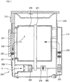
- Fig. 1 is a sectional view of a condenser-type laundry dryer according to the present invention.
- a condenser-type laundry dryer 200 includes an outer case 210, a front cabinet 500 installed at a front of the outer case 210, a cylindrical drum 220 mounted in the outer case 210 to receive the laundry therein, a door 230 controlling the opening of the drum 220, and a belt 221 disposed around an outer circumference of the drum 220 to rotate the drum 220.
- the front cabinet 500 defines a hole for passing air therethrough.
- the condenser-type laundry dryer 200 further includes a motor shaft 280 connected to the belt 221 to transmit rotational force to the drum 220, a motor 270 for transmitting the rotational force to the motor shaft 280, and a cooling fan 260 connected to a first end of the motor shaft 280 to rotate by receiving the rotational force of the motor 270 and intake ambient air.
- the laundry dryer 200 further includes a dry fan 295 connected to a second end of the motor shaft 280 to circulate air in the drum 220 and a duct cover 211 connecting the dry fan 295 to the drum 220 to allow the air introduced by the dry fan 295 to be directed to the drum 220.
- the cooling fan 260 and the dry fan 295 are disposed facing each other and the motor 270 is disposed between the cooling and dry fan 260 and 295.
- the dry fan 295 and a heater 290 are received in the duct cover 211 defining an air passage through which the circulation air introduced by the dry fan 295 is directed to a back of the drum 220.
- the dryer 200 includes a door lint filter 231 disposed on a rear surface of the door 230 for primarily filtering foreign objects contained in the circulation air and a body lint filter 250 disposed under the door lint filter for secondary filtering foreign objects contained in the circulation air passed through the door lint filter 231.
- a circulation duct 251 along which the circulation air passed through the body lint duct 250 is directed to a condenser (refer to 190 in Fig. 2 ).
- the motor 270 rotates and the heater 290 mounted in the duct cover 211 is excited. Then, the belt 221 connected to the motor shaft 280 rotates to rotate the drum 220. As the drum 220 rotates, the laundry in the drum 220 is lifted and dropped by the lift (not shown) mounted on the inner wall of the drum 220.
- the dry fan 295 connected to the motor shaft 280 rotates by the rotation of the motor 270 to introduce the circulation air via the condenser.
- the air flows upward along the duct cover 211 and passes through the heater 290 to be converted into high-temperature/dry air. Then, the air is directed into the drum 220 to absorb the moisture contained in the laundry, thereby being converted into the high-temperature/damp air.
- the high-temperature/damp air is directed to the condenser 190 along the circulation duct 251 after passing through the door lint filter 231 and the body lint filter 250.
- the condenser 190 is designed such that the high-temperature/damp air and the ambient air are not mixed with each other but heat-exchanged.
- the high-temperature/damp air gives heat to the ambient air as it goes through the condenser, thereby being changed into low-temperature/damp air, in the course of which the moisture contained in the low-temperature/damp air is condensed.
- the condensed moisture is dropt on the floor of the condenser 190 and is then directed to a condensed water collector (refer to 150 in Fig. 2 )
- the moisture directed to the condensed water collector 150 is transmitted to a condensed water storage 212 disposed on an upper portion of the dryer 200. Meanwhile, the ambient air passing trough the condenser takes the heat from the high-temperature/damp air to change the circulation air into the lower-temperature/damp air. As a result, the temperature of the ambient air is increased.
- the circulation air introduced by the dry fan 295 flows along the passage defined by the duct cover 211. Then, as it passes through the heater 290, it is changed into the high-temperature/dry air and is then directed into the drum 220.
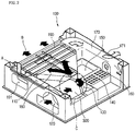
- Fig. 2 is a perspective view of a base with an ambient air inlet structure according to the present invention.
- a base 100 includes an air descending part 110, a condenser insertion hole 191, a condenser 190, and a circulation air passage 170.
- the circulation air enters the base 100 through the air descending part 110 after passing the drum 220 and the door lint filter 231.
- the condenser insertion hole 191 is defined at a bottom front portion of the air descending part 110.
- the condenser 190 is inserted though the condenser insertion hole 191 into the base 100.
- the circulation air passage 170 provides a passage for the circulation air passed the condenser 190.
- the base 100 includes an air inlet 120, a fan mounting space 130, a blower tube 300, and air guide 180.
- the air inlet 120 is defined at a front right of the base 100 to pass ambient air therethrough.
- the fan mounting space 130 is a place where the cooling fan 260 is mounted.
- the blower tube 300 provides a passage for the ambient air from the air inlet 120 to the cooling fan 260.
- the air guide 180 is formed from the fan mounting space 130 to the condenser 190 with an increasing width. Since the cooling fan 260 is a cross flow fan that sucks air in an axial direction and discharges the air in a radial direction, the blower tube 300 and the air guide 180 are connected at a predetermined angle.
- the base 100 includes the motor 270 disposed behind the fan mounting space 130 to rotate the drum 220, heat release holes 140 for passing an air heated by the operation of the motor 270, a shaft hole 160 formed at an end of the circulation air passage 170 for inserting the motor shaft, a condensed water collector 150 formed at about center to collect condensed water dropping from the condenser 190.
- the circulation air which has been heated and damped during passing through the heater 290 and the drum 220, enters the air descending part 110 from the door lint filter 231 and body lint filter 250 and passes through the condenser 190.
- Ambient air is introduced through the air inlet 120 and is blown to the condenser 190 by the cooling fan 260.
- the ambient air takes heat from the high-temperature circulation air.
- the condenser 190 is designed in a cross structure such that the ambient air and circulation air can exchange heat each other without mixing.
- the circulation air passed the condenser 190 moves back to the drum along the circulation air passage 170 and duct cover 211.
- the ambient air passed the condenser is discharged out of the laundry dryer 200.
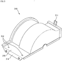
- Fig. 3 is an enlarged partial perspective view of a base with an ambient air inlet structure according to the present invention
- Fig. 4 is an enlarged view of a circular portion "C" depicted in Fig. 2 .
- the base includes a blower tube cover 310 mounted at an exit end of the blower tube 300 to cover the cooling fan 260.
- the blower tube 300 defines a guide holding groove 330 at an inside of its exit end to hold an air guide (refer to 400 in Fig. 7 ).
- the air guide 400 guides the ambient air to the cooling fan 260.
- the guide holding groove 330 is defined between two ribs 330a that are protruded from the base 100 with predetermined heights and widths.
- the ribs 330a is designed such that the air guide 400 can be inserted into the guide holding groove 330 exactly and tightly.
- the fan mounting space 130 is defined behind the guide holding groove 330.
- a tab keeper 340 is formed at an upper surface of the base 100 to fix the blower cover 310.
- the tab keeper 340 is protruded upwardly from the upper surface of the base 100 with a predetermined height and of which end is bent downwardly, such that a cover fixing tab, formed at a side end of the blower cover 310 with a corresponding width (refer to 311 in Fig. 5 ), can be inserted to the tab keeper 340.
- the base 100 includes guide protrusion pockets 350 at an upper surface opposing to the tab keeper 340 to receive guide protrusions (refer to 313 in Fig. 5 )
- cover anchoring holes 360 are defined between the guide protrusion pockets 350 to fix the blower cover 310 to the base 100.
- Fig. 5 is a perspective view showing an outside of a blower cover according to the present invention
- Fig. 6 is a perspective view showing an inside of a blower cover according to the present invention.
- the blower cover 310 which is to be mounted on the base 100 to form a passage for the introduced ambient air, has a semi-cylindrical shape to cover the cooling fan 260.
- the blower cover 310 includes the cover fixing tab 311 projected upwardly with a predetermined height from an end portion, for mounting on the base 100.
- the blower cover 310 includes an extended portion 318 at a side end opposing to the cover fixing tab 311, for mounting on the base 100.
- the extended portion 318 is bent from the side end and extended by a predetermined length.
- the extended portion 318 includes cover fixing holes 312, in which coupling members are to be inserted for fixing the blower cover 310 on the base 100.
- the blower cover 310 includes a bent portion 314 that is extended from an end of the extended portion 318 in a downward direction.
- the bent portion 314 guides the mounting of the blower cover 310 on the base 100 and prevents the blower cover 310 from lateral movement after the mounting.
- the base 100 may define a recessed portion (not shown) having shape and depth corresponding to the bent portion 314 to receive the bent portion 314 exactly.
- the blower cover 310 includes a sealing member 317 attached along its inner edge to be faced with the blower tube 300 in order to prevent the ambient air from leakage. Also, the blower cover 310 defines a guide inserting groove 316 at its inner surface to fix the air guide 400 exactly in the blower cover 310.
- the blower cover 310 includes ribs 316a having predetermined heights and gap therebetween to define the guide inserting groove 316 therebetween.
- the ribs 316a have the same radius of curvature as the air guide 400.
- the guide inserting groove 316 prevents the air guide 400 from forward and backward movements by the ambient air sucked through the blower tube 300.
- blower cover 310 includes a shaft receiving hole 315 to insert the motor shaft 280 to drive the cooling fan 260 with the motor 270.
- the shape of the shaft receiving hole 315 is semi-circular to face an upper portion of the motor shaft 280.
- Another shaft receiving hole 141 with a semi-circular shape is formed at the base 100 (refer to Fig 4 ) to face a lower portion of the motor shaft 280. Therefore, the shaft receiving hole 315 and shaft receiving hole 141 are facing each other to define a circular hole when the blower cover 310 is mounted on the base.
- blower cover 310 includes the guide protrusions 313 at a bottom side of the extended portion 318.
- the guide protrusions 313 arc protruded downwardly with predetermined lengths to exactly align the cover fixing holes 312 with the cover anchoring holes 360 of the base 100.
- the guide protrusions 313 guide the mounting of the blower cover 310 on the base 100, and as well prevent the blower cover 310 from movement on the base 100 when the blower cover 310 is mounted on the base 100.
- the blower cover 310 is placed above the base 100 with facing its shaft receiving hole 315 with the shaft receiving hole 141 of the base, and the cover fixing tab 311 is inserted into the tab keeper 340. Then, the guide protrusions 313 are inserted into the guide protrusion pockets 350 to abut the extended portion 318 on the upper surface of the base 100. Then, coupling members are inserted into the cover fixing holes 312 and the cover anchoring holes 360 to securely fix the blower cover 310 to the base 100.
- the air guide 400 is erected on the base 100 by inserting it on the guide holding groove 330 of the base 100 prior to mounting the blower cover 310 on the base 100, such that the erected air guide 400 can be inserted into the guide inserting groove 316 when the extended portion 318 is abutted on the upper surface of the base 100.
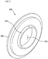
- Fig. 7 is a perspective view of an air guide according to the present invention.
- the outer diameter of the air guide 400 is the same as the inner diameter of the blower tube 300.
- the air guide 400 includes a shroud 410 at a center portion and an air passage hole 420 defined in the shroud 410 to pass the ambient air therethrough.
- the shroud 410 is bent toward the cooling fan 260 to guide the ambient air sucked through the air inlet 120 toward the cooling fan 260.
- the bent portion of the shroud 410 is smoothly rounded to have a predetermined radius of curvature in order to minimize flow friction.
- the air guide 400 reduces the presser of the ambient air flowing therethrough but increases the velocity of the ambient air, thereby increasing the velocity of the ambient air after it passed the cooling fan 260.
- the air guide 400 includes a flange 430 along its circumference.
- the width flange 430 is the same as the widths of the guide holding groove 330 and guide inserting groove 316, and the height of the flange 430 is the same as the depths of the guide holding groove 330 and guide inserting groove 316, such that the flange 430 can be tightly inserted into the guide holding groove 330 and guide inserting groove 316.
- the flange 430 is inserted into the guide holding groove 330, and then the blower cover 310 of which inner barrier rib 33 is hinged to the tab keeper 340 is rotated down to the base 100, such that the guide inserting groove 316 defined inside the blower cover 310 can be coupled with the air guide 400.
- the guide holding groove 330 coupled with the air guide 400 make the air guide 400 stand, it is not required to hold the air guide 400 by the hand when the blower cover 310 is mounted on the base 100.
- Fig. 8 is a partial front view of a laundry dryer with an air inlet structure according to the present invention
- Fig. 9 is a sectional view taken on I-I' line in Fig. 8
- Fig. 10 is a sectional view taken on II-II' line in Fig. 8.
- the front cabinet 500 forms the front external appearance of the laundry dryer 200.
- the door 230 is attached to the front cabinet 500.
- the condenser insertion hole 191 is defined under the door 230 to insert the condenser 190.
- the front cabinet 500 includes a suction hole 522 under the condenser insertion hole 191 to pass the ambient air and a suction grill 520 to cover grill hole 521 in order to guide the suction of the ambient air.
- the number of the suction grill 520 may be at least one, and holes are defined among bars of the suction grill 520.
- the suction hole 521 is defined in front of the base 100 to communicate with the air inlet 120.
- the bars of the suction grill 520 may be designed to point downward at a predetermined angle in order to reduce suction of foreign substances of the ambient air.
- the air blocking part 522 is provided to prevent noise that may be produced when the ambient air is sucked through the portion of the suction grill 520 and collided with front surface of the base 100 where the air inlet 120 is not defined.
- the holes of the suction grill 520 are defined only in front of the air inlet 120 of the base 100, such that the ambient air can be sucked in a straight line toward the cooling fan 260, and the noise produced by the collision between the ambient air and the front surface of the base can be prevented.
Landscapes
- Engineering & Computer Science (AREA)
- Textile Engineering (AREA)
- Detail Structures Of Washing Machines And Dryers (AREA)
Claims (8)
- Sèche-linge ayant un tambour (220) pour charger du linge, un moteur (270) pour entraîner le tambour, une courroie (221) pour relier le tambour et le moteur, un élément chauffant (290) pour chauffer de l'air, dans lequel le sèche-linge comprend :une base (100) définissant une entrée d'air (120) ;un coffret avant (500) disposé devant la base et définissant des trous d'aspiration (521) pour faire passer de l'air ambiant à l'intérieur de la base ;un ventilateur de refroidissement (260) disposé de manière stable dans la base pour aspirer l'air ambiant ;un tube de soufflante (300) formant un passage d'écoulement pour l'air ambiant ;un couvercle de soufflante (310) fixé sur la base (100) pour relier le tube de soufflante (300) et recouvrir le ventilateur de refroidissement (260) ; etun guide d'air (400) disposé entre la base (100) et le couvercle de soufflante (310), le guide d'air (400) présentant une buse au niveau d'une portion centrale,caractérisé en ce que le couvercle de soufflante (310) comporte :une languette de fixation de couvercle (311) faisant saillie vers le haut sur une hauteur prédéterminée depuis une portion d'extrémité ;une portion étendue (318) sur une extrémité latérale opposée à la languette de fixation de couvercle (311) ;une portion courbée (314) courbée et étendue d'une longueur prédéterminée vers le bas depuis une extrémité de la portion étendue (318) ; etdes saillies de guidage (313) faisant saillie depuis un côté inférieur de la portion étendue (318),dans lequel la base (100) comporte :une gâche de languette (340) faisant saillie vers le haut depuis une surface supérieure de celle-ci sur une hauteur prédéterminée et dont une extrémité est courbée vers le bas, pour être couplée à la languette de fixation de couvercle (311) ;des logements de saillies de guidage (350) sur la surface supérieure opposée à la gâche de languette (340) pour recevoir les saillies de guidage (313) ;une portion évidée formée sur une surface latérale de la base (100) pour recevoir la portion courbée (314).
- Sèche-linge selon la revendication 1, dans lequel le coffret avant présente une grille d'aspiration (520) qui est définie par une pluralité de barres,
dans lequel les trous d'aspiration (521) sont formés entre les barres,
et dans lequel les trous d'aspiration (521) sont définis devant l'entrée d'air (120) de la base (100). - Sèche-linge selon la revendication 2, dans lequel les barres définissant la grille d'aspiration (520) sont inclinées vers le bas selon un angle prédéterminé afin de réduire l'aspiration de substances étrangères dans l'air ambiant.
- Sèche-linge selon la revendication 1, dans lequel la base (100) comporte un évidement de montage de ventilateur (130), et le couvercle de soufflante (310) est configuré pour recouvrir une portion ouverte supérieure de l'évidement de montage de ventilateur (130).
- Sèche-linge selon la revendication 1, dans lequel la portion étendue (318) du couvercle de soufflante (310) comporte un trou de fixation de couvercle (312) sur une portion prédéterminée pour faire passer un élément de couplage, et la base (100) comporte un trou d'ancrage de couvercle (360) aligné avec le trou de fixation de couvercle (312) pour recevoir l'élément de couplage.
- Sèche-linge selon la revendication 1, dans lequel le couvercle de soufflante (310) comporte un élément d'étanchéité (317) attaché à un bord inférieur de celui-ci et en contact avec le tube de soufflante (300), pour empêcher l'air ambiant aspiré de fuir.
- Sèche-linge selon la revendication 1, dans lequel le couvercle de soufflante (310) comporte :une paire de nervures (316a) formée le long d'une surface interne sur une hauteur prédéterminée ; etune rainure d'insertion de guidage (316) formée entre la paire de nervures, pour recevoir une partie d'une portion circonférentielle externe du guide d'air (400) .
- Sèche-linge selon la revendication 7, dans lequel la base (100) comporte :une paire de nervures en saillie (330a) faisant saillie sur une hauteur prédéterminée ; etune rainure de support de guidage (330) définie entre la paire de nervures en saillie (330a) pour recevoir la partie externe de la portion circonférentielle externe du guide d'air (400).
Applications Claiming Priority (6)
| Application Number | Priority Date | Filing Date | Title |
|---|---|---|---|
| KR1020030093671A KR101079899B1 (ko) | 2003-12-19 | 2003-12-19 | 건조기의 실내공기 흡입구조 |
| KR2003093672 | 2003-12-19 | ||
| KR1020030093672A KR101079972B1 (ko) | 2003-12-19 | 2003-12-19 | 건조기의 실내공기 흡입구조 |
| KR2003093671 | 2003-12-19 | ||
| KR1020030097561A KR101079999B1 (ko) | 2003-12-26 | 2003-12-26 | 건조기의 실내공기 흡입구조 |
| KR2003097561 | 2003-12-26 |
Publications (3)
| Publication Number | Publication Date |
|---|---|
| EP1555342A2 EP1555342A2 (fr) | 2005-07-20 |
| EP1555342A3 EP1555342A3 (fr) | 2013-11-20 |
| EP1555342B1 true EP1555342B1 (fr) | 2017-08-02 |
Family
ID=34623606
Family Applications (1)
| Application Number | Title | Priority Date | Filing Date |
|---|---|---|---|
| EP04293021.4A Not-in-force EP1555342B1 (fr) | 2003-12-19 | 2004-12-17 | Sèche-lave linge et structure de l'entrée d'air |
Country Status (2)
| Country | Link |
|---|---|
| US (2) | US7093377B2 (fr) |
| EP (1) | EP1555342B1 (fr) |
Families Citing this family (21)
| Publication number | Priority date | Publication date | Assignee | Title |
|---|---|---|---|---|
| KR100556503B1 (ko) * | 2002-11-26 | 2006-03-03 | 엘지전자 주식회사 | 건조기의 건조 시간제어 방법 |
| KR101093878B1 (ko) * | 2004-06-05 | 2011-12-13 | 엘지전자 주식회사 | 건조기의 드럼 장치 |
| KR101093988B1 (ko) * | 2004-06-05 | 2011-12-15 | 엘지전자 주식회사 | 건조기의 도어 린트 필터 밀착 장치 |
| KR100662369B1 (ko) * | 2004-11-30 | 2007-01-02 | 엘지전자 주식회사 | 열풍공급용 옷걸이가 구비된 복합식 건조장치 |
| US7908766B2 (en) * | 2004-12-06 | 2011-03-22 | Lg Electronics Inc. | Clothes dryer |
| DE102006002713A1 (de) * | 2005-03-18 | 2006-10-12 | BSH Bosch und Siemens Hausgeräte GmbH | Frontbaugruppe für eine Wäschetrockenmaschine |
| KR100638936B1 (ko) * | 2005-03-31 | 2006-10-25 | 엘지전자 주식회사 | 건조기의 캐비닛 구조 |
| US8104192B2 (en) * | 2005-03-31 | 2012-01-31 | Lg Electronics Inc. | Laundry dryer |
| DE102005023446A1 (de) * | 2005-05-20 | 2006-11-23 | BSH Bosch und Siemens Hausgeräte GmbH | Haushaltgerät zur Pflege von Wäschestücken, insbesondere Wäschetrockner |
| DE102007007133A1 (de) * | 2007-02-13 | 2008-08-14 | Meiko Maschinenbau Gmbh & Co. Kg | Frontlader-Geschirrspülmaschine mit Wärmerückgewinnung |
| DE102007049959A1 (de) * | 2007-10-18 | 2009-04-23 | BSH Bosch und Siemens Hausgeräte GmbH | Flusenfiltervorrichtung und Hausgerät mit einer derartigen Flusenfiltervorrichtung |
| KR101256145B1 (ko) * | 2007-11-05 | 2013-04-23 | 동부대우전자 주식회사 | 히터 내장형 흡기관을 구비하는 건조기 |
| KR101308510B1 (ko) * | 2007-11-05 | 2013-09-12 | 동부대우전자 주식회사 | 히터 내장형 흡기관을 구비하는 건조기 |
| KR20100034077A (ko) * | 2008-09-23 | 2010-04-01 | 삼성전자주식회사 | 의류건조기 |
| EP2204487A1 (fr) * | 2008-12-30 | 2010-07-07 | Electrolux Home Products Corporation N.V. | Appareil domestique pour sécher les vêtements |
| US8424834B2 (en) * | 2009-06-24 | 2013-04-23 | Magna International | Composite appliance base |
| EP2519793B1 (fr) * | 2009-12-31 | 2018-03-21 | LG Electronics Inc. | Réfrigérateur |
| US8899480B2 (en) | 2011-03-28 | 2014-12-02 | Everyone Counts Inc. | Systems and methods for remaking ballots |
| US8843389B2 (en) | 2011-06-24 | 2014-09-23 | Everyone Counts, Inc. | Mobilized polling station |
| US11174586B2 (en) * | 2019-09-10 | 2021-11-16 | Haier Us Appliance Solutions, Inc. | Vortex dryer appliance |
| WO2021096560A1 (fr) * | 2019-11-15 | 2021-05-20 | Napat Thawornsing | Surligneur transparent |
Family Cites Families (9)
| Publication number | Priority date | Publication date | Assignee | Title |
|---|---|---|---|---|
| DE3135292A1 (de) * | 1981-09-05 | 1983-03-24 | Licentia Patent-Verwaltungs-Gmbh, 6000 Frankfurt | "kunststofftragkoerper fuer einen waeschetrockner" |
| IT209164Z2 (it) * | 1985-08-02 | 1988-09-16 | Zanussi Elettrodomestici | Asciugabiancheria a condensazione. |
| JPH0772624B2 (ja) * | 1989-12-29 | 1995-08-02 | 三洋電機株式会社 | 空気調和機 |
| US5555647A (en) * | 1995-08-23 | 1996-09-17 | White Consolidated Industries, Inc. | Motor mounted to blower housing |
| US6345511B1 (en) * | 1999-02-25 | 2002-02-12 | Kooltronic, Incorporated | Air handling apparatus |
| DE10202442B4 (de) * | 2002-01-22 | 2005-02-03 | Miele & Cie. Kg | Bodenmodul für einen Kondensationswäschetrockner |
| KR100465729B1 (ko) * | 2003-01-15 | 2005-01-13 | 엘지전자 주식회사 | 건조기 |
| KR100487759B1 (ko) * | 2003-08-13 | 2005-05-06 | 엘지전자 주식회사 | 의류건조기의 냉각공기 흡입구조 |
| SI1516953T1 (sl) * | 2003-09-22 | 2008-02-29 | Electrolux Home Prod Corp | Gospodinjski stroj za susenje perila kondenzacijskega tipa z nizko glasnostjo |
-
2004
- 2004-12-17 EP EP04293021.4A patent/EP1555342B1/fr not_active Not-in-force
- 2004-12-17 US US11/013,422 patent/US7093377B2/en not_active Expired - Fee Related
-
2006
- 2006-06-21 US US11/471,590 patent/US7406780B2/en active Active
Non-Patent Citations (1)
| Title |
|---|
| None * |
Also Published As
| Publication number | Publication date |
|---|---|
| EP1555342A3 (fr) | 2013-11-20 |
| US20050166421A1 (en) | 2005-08-04 |
| US7406780B2 (en) | 2008-08-05 |
| US7093377B2 (en) | 2006-08-22 |
| US20060236560A1 (en) | 2006-10-26 |
| EP1555342A2 (fr) | 2005-07-20 |
Similar Documents
| Publication | Publication Date | Title |
|---|---|---|
| US7406780B2 (en) | Laundry dryer air guide pressure/friction altering feature | |
| EP1541741B1 (fr) | Sèche-linge. | |
| EP1548178A2 (fr) | Sèche-linge et son condenseur | |
| EP1541743B1 (fr) | Sèche-linge avec panier de séchage | |
| EP1548176B1 (fr) | Sèche-linge avec dispositif de soutien du tambour correspondant | |
| EP3045581B1 (fr) | Séchoir | |
| JP4490799B2 (ja) | 乾燥機の空気循環構造 | |
| EP3045582B1 (fr) | Séchoir | |
| US10718081B2 (en) | Drain pump for laundry treating apparatus | |
| KR101093878B1 (ko) | 건조기의 드럼 장치 | |
| EP1548172B1 (fr) | Sèche-linge et structure pour l'assemblage du moteur | |
| CN114941233B (zh) | 衣物处理装置 | |
| US20180371677A1 (en) | Dryer | |
| EP1666659A1 (fr) | Sèche-linge | |
| KR100585323B1 (ko) | 의류건조기 | |
| KR101942075B1 (ko) | 의류건조기 | |
| KR20230111120A (ko) | 의류처리장치 | |
| KR101093865B1 (ko) | 건조기의 순환 공기 안내 장치 | |
| KR20230007049A (ko) | 의류 처리장치 | |
| KR101094053B1 (ko) | 건조기의 백커버 강도 보강 장치 | |
| KR20050063126A (ko) | 건조기의 프런트 실링 조립구조 | |
| KR20050063127A (ko) | 건조기의 프런트 실링 조립구조 |
Legal Events
| Date | Code | Title | Description |
|---|---|---|---|
| PUAI | Public reference made under article 153(3) epc to a published international application that has entered the european phase |
Free format text: ORIGINAL CODE: 0009012 |
|
| AK | Designated contracting states |
Kind code of ref document: A2 Designated state(s): AT BE BG CH CY CZ DE DK EE ES FI FR GB GR HU IE IS IT LI LT LU MC NL PL PT RO SE SI SK TR |
|
| AX | Request for extension of the european patent |
Extension state: AL BA HR LV MK YU |
|
| PUAL | Search report despatched |
Free format text: ORIGINAL CODE: 0009013 |
|
| AK | Designated contracting states |
Kind code of ref document: A3 Designated state(s): AT BE BG CH CY CZ DE DK EE ES FI FR GB GR HU IE IS IT LI LT LU MC NL PL PT RO SE SI SK TR |
|
| AX | Request for extension of the european patent |
Extension state: AL BA HR LV MK YU |
|
| RIC1 | Information provided on ipc code assigned before grant |
Ipc: D06F 58/04 20060101AFI20131014BHEP |
|
| 17P | Request for examination filed |
Effective date: 20140516 |
|
| RBV | Designated contracting states (corrected) |
Designated state(s): AT BE BG CH CY CZ DE DK EE ES FI FR GB GR HU IE IS IT LI LT LU MC NL PL PT RO SE SI SK TR |
|
| AKX | Designation fees paid |
Designated state(s): AT BE BG CH CY CZ DE DK EE ES FI FR GB GR HU IE IS IT LI LT LU MC NL PL PT RO SE SI SK TR |
|
| 17Q | First examination report despatched |
Effective date: 20160805 |
|
| GRAJ | Information related to disapproval of communication of intention to grant by the applicant or resumption of examination proceedings by the epo deleted |
Free format text: ORIGINAL CODE: EPIDOSDIGR1 |
|
| GRAP | Despatch of communication of intention to grant a patent |
Free format text: ORIGINAL CODE: EPIDOSNIGR1 |
|
| INTG | Intention to grant announced |
Effective date: 20170317 |
|
| GRAS | Grant fee paid |
Free format text: ORIGINAL CODE: EPIDOSNIGR3 |
|
| GRAA | (expected) grant |
Free format text: ORIGINAL CODE: 0009210 |
|
| AK | Designated contracting states |
Kind code of ref document: B1 Designated state(s): AT BE BG CH CY CZ DE DK EE ES FI FR GB GR HU IE IS IT LI LT LU MC NL PL PT RO SE SI SK TR |
|
| REG | Reference to a national code |
Ref country code: GB Ref legal event code: FG4D |
|
| REG | Reference to a national code |
Ref country code: CH Ref legal event code: EP Ref country code: AT Ref legal event code: REF Ref document number: 914598 Country of ref document: AT Kind code of ref document: T Effective date: 20170815 |
|
| REG | Reference to a national code |
Ref country code: IE Ref legal event code: FG4D |
|
| REG | Reference to a national code |
Ref country code: DE Ref legal event code: R096 Ref document number: 602004051607 Country of ref document: DE |
|
| REG | Reference to a national code |
Ref country code: NL Ref legal event code: MP Effective date: 20170802 |
|
| REG | Reference to a national code |
Ref country code: AT Ref legal event code: MK05 Ref document number: 914598 Country of ref document: AT Kind code of ref document: T Effective date: 20170802 |
|
| REG | Reference to a national code |
Ref country code: LT Ref legal event code: MG4D |
|
| PG25 | Lapsed in a contracting state [announced via postgrant information from national office to epo] |
Ref country code: AT Free format text: LAPSE BECAUSE OF FAILURE TO SUBMIT A TRANSLATION OF THE DESCRIPTION OR TO PAY THE FEE WITHIN THE PRESCRIBED TIME-LIMIT Effective date: 20170802 Ref country code: NL Free format text: LAPSE BECAUSE OF FAILURE TO SUBMIT A TRANSLATION OF THE DESCRIPTION OR TO PAY THE FEE WITHIN THE PRESCRIBED TIME-LIMIT Effective date: 20170802 Ref country code: LT Free format text: LAPSE BECAUSE OF FAILURE TO SUBMIT A TRANSLATION OF THE DESCRIPTION OR TO PAY THE FEE WITHIN THE PRESCRIBED TIME-LIMIT Effective date: 20170802 Ref country code: SE Free format text: LAPSE BECAUSE OF FAILURE TO SUBMIT A TRANSLATION OF THE DESCRIPTION OR TO PAY THE FEE WITHIN THE PRESCRIBED TIME-LIMIT Effective date: 20170802 Ref country code: FI Free format text: LAPSE BECAUSE OF FAILURE TO SUBMIT A TRANSLATION OF THE DESCRIPTION OR TO PAY THE FEE WITHIN THE PRESCRIBED TIME-LIMIT Effective date: 20170802 |
|
| PG25 | Lapsed in a contracting state [announced via postgrant information from national office to epo] |
Ref country code: GR Free format text: LAPSE BECAUSE OF FAILURE TO SUBMIT A TRANSLATION OF THE DESCRIPTION OR TO PAY THE FEE WITHIN THE PRESCRIBED TIME-LIMIT Effective date: 20171103 Ref country code: IS Free format text: LAPSE BECAUSE OF FAILURE TO SUBMIT A TRANSLATION OF THE DESCRIPTION OR TO PAY THE FEE WITHIN THE PRESCRIBED TIME-LIMIT Effective date: 20171202 Ref country code: ES Free format text: LAPSE BECAUSE OF FAILURE TO SUBMIT A TRANSLATION OF THE DESCRIPTION OR TO PAY THE FEE WITHIN THE PRESCRIBED TIME-LIMIT Effective date: 20170802 Ref country code: BG Free format text: LAPSE BECAUSE OF FAILURE TO SUBMIT A TRANSLATION OF THE DESCRIPTION OR TO PAY THE FEE WITHIN THE PRESCRIBED TIME-LIMIT Effective date: 20171102 Ref country code: PL Free format text: LAPSE BECAUSE OF FAILURE TO SUBMIT A TRANSLATION OF THE DESCRIPTION OR TO PAY THE FEE WITHIN THE PRESCRIBED TIME-LIMIT Effective date: 20170802 |
|
| PGFP | Annual fee paid to national office [announced via postgrant information from national office to epo] |
Ref country code: GB Payment date: 20171220 Year of fee payment: 14 |
|
| PG25 | Lapsed in a contracting state [announced via postgrant information from national office to epo] |
Ref country code: CZ Free format text: LAPSE BECAUSE OF FAILURE TO SUBMIT A TRANSLATION OF THE DESCRIPTION OR TO PAY THE FEE WITHIN THE PRESCRIBED TIME-LIMIT Effective date: 20170802 Ref country code: DK Free format text: LAPSE BECAUSE OF FAILURE TO SUBMIT A TRANSLATION OF THE DESCRIPTION OR TO PAY THE FEE WITHIN THE PRESCRIBED TIME-LIMIT Effective date: 20170802 Ref country code: RO Free format text: LAPSE BECAUSE OF FAILURE TO SUBMIT A TRANSLATION OF THE DESCRIPTION OR TO PAY THE FEE WITHIN THE PRESCRIBED TIME-LIMIT Effective date: 20170802 |
|
| REG | Reference to a national code |
Ref country code: DE Ref legal event code: R097 Ref document number: 602004051607 Country of ref document: DE |
|
| PG25 | Lapsed in a contracting state [announced via postgrant information from national office to epo] |
Ref country code: SK Free format text: LAPSE BECAUSE OF FAILURE TO SUBMIT A TRANSLATION OF THE DESCRIPTION OR TO PAY THE FEE WITHIN THE PRESCRIBED TIME-LIMIT Effective date: 20170802 Ref country code: EE Free format text: LAPSE BECAUSE OF FAILURE TO SUBMIT A TRANSLATION OF THE DESCRIPTION OR TO PAY THE FEE WITHIN THE PRESCRIBED TIME-LIMIT Effective date: 20170802 |
|
| PLBE | No opposition filed within time limit |
Free format text: ORIGINAL CODE: 0009261 |
|
| STAA | Information on the status of an ep patent application or granted ep patent |
Free format text: STATUS: NO OPPOSITION FILED WITHIN TIME LIMIT |
|
| 26N | No opposition filed |
Effective date: 20180503 |
|
| REG | Reference to a national code |
Ref country code: CH Ref legal event code: PL |
|
| PG25 | Lapsed in a contracting state [announced via postgrant information from national office to epo] |
Ref country code: SI Free format text: LAPSE BECAUSE OF FAILURE TO SUBMIT A TRANSLATION OF THE DESCRIPTION OR TO PAY THE FEE WITHIN THE PRESCRIBED TIME-LIMIT Effective date: 20170802 |
|
| REG | Reference to a national code |
Ref country code: IE Ref legal event code: MM4A |
|
| PG25 | Lapsed in a contracting state [announced via postgrant information from national office to epo] |
Ref country code: LU Free format text: LAPSE BECAUSE OF NON-PAYMENT OF DUE FEES Effective date: 20171217 |
|
| REG | Reference to a national code |
Ref country code: FR Ref legal event code: ST Effective date: 20180831 |
|
| REG | Reference to a national code |
Ref country code: BE Ref legal event code: MM Effective date: 20171231 |
|
| PG25 | Lapsed in a contracting state [announced via postgrant information from national office to epo] |
Ref country code: FR Free format text: LAPSE BECAUSE OF NON-PAYMENT OF DUE FEES Effective date: 20180102 Ref country code: IE Free format text: LAPSE BECAUSE OF NON-PAYMENT OF DUE FEES Effective date: 20171217 |
|
| PG25 | Lapsed in a contracting state [announced via postgrant information from national office to epo] |
Ref country code: CH Free format text: LAPSE BECAUSE OF NON-PAYMENT OF DUE FEES Effective date: 20171231 Ref country code: BE Free format text: LAPSE BECAUSE OF NON-PAYMENT OF DUE FEES Effective date: 20171231 Ref country code: LI Free format text: LAPSE BECAUSE OF NON-PAYMENT OF DUE FEES Effective date: 20171231 |
|
| PG25 | Lapsed in a contracting state [announced via postgrant information from national office to epo] |
Ref country code: MC Free format text: LAPSE BECAUSE OF FAILURE TO SUBMIT A TRANSLATION OF THE DESCRIPTION OR TO PAY THE FEE WITHIN THE PRESCRIBED TIME-LIMIT Effective date: 20170802 Ref country code: HU Free format text: LAPSE BECAUSE OF FAILURE TO SUBMIT A TRANSLATION OF THE DESCRIPTION OR TO PAY THE FEE WITHIN THE PRESCRIBED TIME-LIMIT; INVALID AB INITIO Effective date: 20041217 |
|
| GBPC | Gb: european patent ceased through non-payment of renewal fee |
Effective date: 20181217 |
|
| PG25 | Lapsed in a contracting state [announced via postgrant information from national office to epo] |
Ref country code: CY Free format text: LAPSE BECAUSE OF NON-PAYMENT OF DUE FEES Effective date: 20170802 |
|
| PG25 | Lapsed in a contracting state [announced via postgrant information from national office to epo] |
Ref country code: GB Free format text: LAPSE BECAUSE OF NON-PAYMENT OF DUE FEES Effective date: 20181217 |
|
| PGFP | Annual fee paid to national office [announced via postgrant information from national office to epo] |
Ref country code: DE Payment date: 20191105 Year of fee payment: 16 |
|
| PGFP | Annual fee paid to national office [announced via postgrant information from national office to epo] |
Ref country code: IT Payment date: 20191218 Year of fee payment: 16 |
|
| PG25 | Lapsed in a contracting state [announced via postgrant information from national office to epo] |
Ref country code: TR Free format text: LAPSE BECAUSE OF FAILURE TO SUBMIT A TRANSLATION OF THE DESCRIPTION OR TO PAY THE FEE WITHIN THE PRESCRIBED TIME-LIMIT Effective date: 20170802 |
|
| PG25 | Lapsed in a contracting state [announced via postgrant information from national office to epo] |
Ref country code: PT Free format text: LAPSE BECAUSE OF FAILURE TO SUBMIT A TRANSLATION OF THE DESCRIPTION OR TO PAY THE FEE WITHIN THE PRESCRIBED TIME-LIMIT Effective date: 20170802 |
|
| REG | Reference to a national code |
Ref country code: DE Ref legal event code: R119 Ref document number: 602004051607 Country of ref document: DE |
|
| PG25 | Lapsed in a contracting state [announced via postgrant information from national office to epo] |
Ref country code: IT Free format text: LAPSE BECAUSE OF NON-PAYMENT OF DUE FEES Effective date: 20201217 |
|
| PG25 | Lapsed in a contracting state [announced via postgrant information from national office to epo] |
Ref country code: DE Free format text: LAPSE BECAUSE OF NON-PAYMENT OF DUE FEES Effective date: 20210701 |